
Ferroelectric Materials Based Coupled Nanogenerators


1
CAS Center for Excellence in Nanoscience, Beijing Key Laboratory of Micro-Nano Energy and Sensor, Beijing Institute of Nanoenergy and Nanosystems, Chinese Academy of Sciences, Beijing 101400, China
2
School of Nanoscience and Technology, University of Chinese Academy of Sciences, Beijing 100049, China
3
Center on Nanoenergy Research, School of Physical Science and Technology, Guangxi University, Nanning 530004, China
*
Author to whom correspondence should be addressed.
Nanoenergy Adv. 2021, 1(2), 131-180; https://0-doi-org.brum.beds.ac.uk/10.3390/nanoenergyadv1020007
Submission received: 9 October 2021
/
Revised: 18 November 2021
/
Accepted: 19 November 2021
/
Published: 25 November 2021
(This article belongs to the Special Issue Recent Advances in Nanogenerators)
Abstract
:Innovations in nanogenerator technology foster pervading self-power devices for human use, environmental surveillance, energy transfiguration, intelligent energy storage systems, and wireless networks. Energy harvesting from ubiquitous ambient mechanical, thermal, and solar energies by nanogenerators is the hotspot of the modern electronics research era. Ferroelectric materials, which show spontaneous polarization, are reversible when exposed to the external electric field, and are responsive to external stimuli of strain, heat, and light are promising for modeling nanogenerators. This review demonstrates ferroelectric material-based nanogenerators, practicing the discrete and coupled pyroelectric, piezoelectric, triboelectric, and ferroelectric photovoltaic effects. Their working mechanisms and way of optimizing their performances, exercising the conjunction of effects in a standalone device, and multi-effects coupled nanogenerators are greatly versatile and reliable and encourage resolution in the energy crisis. Additionally, the expectancy of productive lines of future ensuing and propitious application domains are listed.

1. Introduction
With the advancement in modern mobile electronics, wireless communication systems, and the internet of things (IoT), researchers became more concerned with the miniaturization and multi-functionality of devices, e.g., low power, flexibility, etc. Mobile devices are handy and carry information that is immediately accessible and transmittable wirelessly. The devices are small enough to be worn or fastened with objects of everyday use, such as goggles, clothes, wristwatches, and many others. These minuscule devices need small operational powers, usually in micro-watt or milli-watt, for which the use of the traditional chemical batteries is a miser and are the cause of environmental threaten, too; hence, small-scale sustainable power solutions are in need. The make-up to this innovates the maturing of energy harvesting units, which can efficiently harvest energy, such as mechanical, heat, and light energy, to electrical energy and reuse sources of energies from the ambient atmosphere [1,2,3,4]. In 2006, Z. L. Wang and J. Song developed nanogenerators (NGs) by transforming nanoscale mechanical energy into electricity using arrays of piezoelectric ZnO nanowire and marked energy harvesters to jump into a new span [5]. The basic theory of nanogenerators was established based on the concept of the use of the Maxwell displacement current as a driving force to convert environmental energies into electrical energy signals. Therefore, NGs work by current generations and employ the concept of internal polarization of the material [6]. Out of thirty-two crystal structures, twenty-one crystal classes do not possess central symmetry and are non-centrosymmetric, twenty of which show polarization as the reaction of mechanical stress forces are piezoelectric and, among these, twenty (1, 2, m, 222, mm2, 4, −4, 422, 4 mm, −42 m, 3, 32, 3 m, 6, −6, 622 m 6 mm, −62 m, 23, −43 m). Among these twenty piezoelectrics, ten show spontaneous polarization variations, induced by temperature changes are pyroelectric (1, 2, m, mm2, 3, 3 m, 4, 4 mm, 6, 6 mm). Their polarization turned out to be reversed with the implementation of the electric field; additionally, the particular materials are ferroelectrics [7,8]. Ferroelectrics are functional dielectric materials that have shown spectacular properties of spontaneous polarization at zero electric fields. The spontaneous polarization (Ps) can be switched to reversed direction when a large poling electric field (in units of kV/cm to MV/cm) is applied. Figure 1a(i) demonstrates the typical ferroelectric P-E curve [9], showing both the states are steady and thermodynamically stable. Thus, ferroelectric materials have been of great research interest for almost over a century [10,11]. In conventional ferroelectric (FE) materials, also known as proper ferroelectrics, the spontaneous polarization (Ps) is responsible for the change in structure (i.e., structural phase transition) breaking the crystal symmetry at curie temperature (Tc). So, the order parameter of phase transition in proper ferroelectrics is spontaneous polarization. Ferroelectrics have posted a wide range of applications contributing to frequency filters, pressure and temperature sensors, actuators, hydrophones, oscillators, and many others [12,13,14,15,16,17,18]. Since all the ferroelectrics are piezoelectric and pyroelectric, they speculate the phenomenon of piezoelectricity, pyroelectricity, and photovoltaic ferroelectric effects. These effects are the result of responses from external stimuli, such as mechanical, thermal, and solar energies, respectively [19,20,21,22]. The piezoelectric coefficient of semiconductor piezoelectric ZnO is ~12 pC/N, which is quite low, in contrast to the ferroelectric materials with perovskite structure, e.g., BaTiO3 and Pb(Zr, Ti)O3, which exhibit high piezoelectric coefficients of 100 pC/N and 200 pC/N, respectively [23]. These properties of ferroelectrics promote their use in the fabrication of nanogenerators for energy scavenging and harvesting from low frequency natural and artificial energy sources from the environment [24,25]. Along with energy storage units, self-powered systems can also be integrated by nanogenerators for powering functional devices. Many nanogenerators have been fashioned after, including piezoelectric NGs (PENG), pyroelectric NGs (PyENG), triboelectric NGs (TENG), and photovoltaics (PVC) [26,27,28,29]. Piezoelectric and triboelectric NGs transform mechanical stress forces and/or energies from wind/airflow, water waves, human motions, biomechanical energies, etc., to electrical energy, accompanied by changing polarization degrees in ferroelectrics [30,31,32,33,34,35]. Pyroelectric NGs works by temperature variations from industrial heat wastes, radiations from the sun, etc. [36,37,38,39,40,41]. The photovoltaic effect in ferroelectrics demonstrated that the photocurrent is not limited by the bandgap of material; rather, it is associated with material polarity and separation of light-induced photo carriers [42,43,44,45]. At present, hybrid nanogenerators and multi-effect coupled NGs are of practical interest, developed by integrating the above mentioned effects into a single structure and, hence, contributing to the maximization of energies for high electrical power outputs, depending on the strength of external stimuli [6,46,47,48,49,50]. The ever first one-structured coupled nanogenerator, based on piezo–tribo–pyro–photovoltaic effects, was proposed by professor Ya Yang and his co-workers in 2015 [51]. Ferroelectric materials possess permanent dipole moments in the electric field, which increases their polarization density and facilitates their use in wearable, flexible electronics. The conventional semiconductor materials do not own this property and so ferroelectrics gather more attention [52]. The most active ferroelectric materials encapsulated in nanogenerator application are inorganic ferroelectric ceramics and organic polymers; the best of them include BaTiO3 (BTO) [53], PbZr1-xTixO3 (PZT) [54], Na0.5Bi0.5TiO3 (NBT) [55], KNaNbO3 (KNN) [56], BiFeO3 (BFO) [57], Pb(Mg1/3Nb2/3)O3-PbTiO3 (PMN-PT) [58], PVDF [59,60,61], and P(VDF-TrFE) [62]. In comparison with inorganic ferroelectrics, very few organic ferroelectrics exist. For example, single-component polar organic molecules, such as CDA, DNP, CT complexes, and polymers, such as PVDF, nylon-11, and organic-inorganic composites, such as HdabecoReO4, TGS, TSCC, are excellent for applications in piezoelectric and triboelectric nanogenerators [63]. Other reports on semiconductor ferroelectric have also been found. Ferroelectric polymers are highly flexible and have found applications in wearable and foldable devices. Ferroelectric ceramics are hard and are often complexed with other ferroelectric/non-ferroelectric material and stacked to multilayered architecture, in order to improve their output features with various structural morphologies and, e.g., (Ba0.85Ca0.15)(Ti0.90Zr0.10)O3-x BiHoO3/PDMS [64], PDMS/PZT [65], and CNTs-PMNT/PDMS [66]. In this peer review paper, we briefly talk about the basic properties of ferroelectric materials, together with related phenomena for energy conversion, i.e., piezoelectricity, pyroelectricity, triboelectricity, and ferroelectric photovoltaic effects, as well as operating conditions of various types of ferroelectric material-based NGs. Mechanism of ferroelectrics-based hybrid and multi-effect coupled NGs, with their structure-related performances and power conversion efficiencies, are also discussed. Some recent applications, including self-powered micro/nano-systems, multifunctional sensors, and wearable flexible devices, are discussed. Furthermore, the advantages of ferroelectric-based NGs and future prospects are devised.
2. Ferroelectric Materials
2.1. Fortunes of Ferroelectric Materials
Ferroelectric materials in their ferroelectric phase exhibit net dipole moment, i.e., the centers of charges (positive and negative) do not coincide, resulting in robust polarization lasting permanently below a particular temperature, called the curie temperature (Tc), in the non-poled state. Before the time of the second world war, from 1920–1943, ferroelectric materials remained of academic and theoretical interest for small applications zones. In the 1950s, BaTiO3 (BTO) discovered that strong ferroelectric behavior evoked the electronic ceramic industry and became an interesting candidate for piezoelectric transducers. By the 1960s, researchers undertook ferroelectric thin films and realized practicing non-volatile memories, but quality maintenance, restricted their practical applications, up until the 1980s; later in the 1990s, ferroelectrics, alongside microsensors, found widespread applications in radio frequency and microwave devices. In 1994, the bypass ferroelectric capacitors installed in digital mobile phones provided a breakthrough in the leading micro-digital industry [69,70,71]. For the past two decades, ferroelectric materials subsisted a great application tempt in energy harvesting.
2.2. Crystal Structures
Joesph Valasek has discovered the phenomenon of ferroelectricity in Rochelle salt (NaKC4H4O6.4H2O) orthorhombic crystal structure first. Up until now, more than seven hundred ferroelectric materials have been demonstrated, inclusive of oxides, polymers, ceramics, and liquid crystals, as well. Typical ferroelectric materials have either ABO3 perovskite or hydrogen-bonded potassium dihydrate phosphate KH2PO4 (KDP) structures, but others also exist, such as GeTe, SrAlF5, SbSI, SbSeI, etc. [72,73]. Perovskite ferroelectric materials are with crystal structure isomorphous to the mineral perovskite calcium titanium oxide CaTiO3, general formula ABO3, whereupon A and B stand as cation, and O is the oxygen ion. The ionic radius of cation A and B is particularly around 1.2 Å to 1.6 Å and 0.6 Å to 0.7 Å, respectively. Oxygen atoms/ions are positioned at the face center and A ion at the cube corner, forming octahedral surrounding B ions and staying at the body center. Structure stability requires that the valencies of ions be balanced. Moreover, the structural distortions, such as octahedral distortion or tilting, associated with low space group symmetries, cause relief of B-site electronic instabilities, leading to high values of ferroelectric polarization, piezoelectric coefficients, unusual photovoltaic behaviors, and dielectric constants [7]. Figure 1a(ii) represent perovskite structure-based inorganic ferroelectric materials, such as lead zirconate titanate PZT (Pb(TixZr1−x)O3), barium titanate BTO (BaTiO3), and layered strontium bismuth tantalite SBT (SrBi2Ta2O9); in all of them, the central cation switches its position between the stable states [9]. The literature revealed the existence of morphotropic phase boundary (MBP) in PZT, with compositional variations that benefited piezo ceramics a lot [74,75,76,77]. Furthermore, the nature of lead (Pb) is weighty and detrimental to humans and the environment. Therefore, lead-free materials (e.g., BiFeO3 (BFO), KNaNbO3 (KNN), etc.) which are non-toxic, environmentally friendly, and biocompatible, are of more research interest [78,79]. Some ferroelectrics, with more complex perovskite structures, have also been observed with cations of different valencies but fixed molar concentrations. For example, PbMg1/3Nb2O3 (PMN), PbSc1/2Ta1/2O3 (PST), and Bi1/2Na1/2TiO3 (BNT) [80,81]. Ferroelectric hafnium oxide (HfO2) is also of great interest and becoming a spotlight for the memories industry [9].
Ferroelectrics with ilmenite structure are similar to perovskites, with distinction in the A cation, which is small enough to fill ABO3 structure coordinated site. Oxygen ions are packed closely in a hexagonal layer, with cations A and B located between the layers at octahedral sites LiNbO3 and LiTaO3, which are two important uniaxial ferroelectric materials of this class [82,83,84].
Polyvinylidene fluoride (PVDF) with CH2CF2 monomer was observed to be the first ferroelectric polymer, without any particular curie temperature, as melting occurs first. PVDF exists in four different polymorphs (i.e., the phases), depending on the configuration of carbon–carbon links. Fluorine atoms are electronegative and make the C–F bond polar, resulting in the molecule having a net dipole moment orthogonal to molecular length carbon backbone chain. Though the molecules of polymer arrange in the unit cell and, hence, the dipoles balance each other in the -phase; so, the PVDF in -phase is not ferroelectric, but its field application produces a net dipole moment on unit cell and put it in -phase. Annealing of these systems at high temperatures crystalizes them in the -phase, which also has a net dipole moment perpendicular to the carbon backbone and is polar. Orthorhombic -phase can be achieved by stretch or draw in previously derived phases and is an all-trans configuration with high spontaneous polarization and a dielectric constant [85]. So, electric poling makes -PVDF-phase a strong piezoelectric and pyroelectric phase, when compared with other polymorphs. -PVDF-phase can be directly obtained by the copolymerization of vinylidene fluoride with trifluroethylene TrFE (~10 to 46% by wt.); the resultant P(VDF-TrFE) material has the same activity rate as pure PVDF but exhibits high remnant polarization [82,86,87]. Figure 1a(iii,iv) show the switching behavior of polar polymer chains in organic ferroelectric polyvinylidene fluoride (PVDF) polymerized, with tetrafluoroethylene (TrFE) and O−2 ion switching in fluoride structure of orthorhombic hafnium oxide (HfO2), respectively [9]. Hexafluoropropylene HFP is another important copolymer material for the PVDF matrix. Other polymers that exhibit ferroelectric behavior include odd-numbered nylons, but these are only weakly piezoelectric. These polymeric ferroelectrics are useful in flexible electronics, especially in wearable devices.
Another class of ferroelectrics comprises of improper ferroelectrics, for those in which the order parameter is not the polarization; rather, the spontaneous polarization arises as to the by-product of phase transition, as a secondary effect. The temperature dependence of the permittivity does not follow Curie–Wiess law; additionally, the phase transition is not suppressed by the electric fields in improper ferroelectrics [88]. The dielectric constant of improper ferroelectric remains low, usually near the phase transition temperature, and is conducive to the large pyroelectric figure of merits. Examples of improper ferroelectric involve iron-iodine-boracite [FeB7O13I (TMO)], dicalcium-lead-propionate [Ca2Pb(CH3CH2COO)6 (DLP)], [Hdabeco]ClO4, etc., [89]. A subset of ferroelectric materials forms ferroelastic materials, which may show spontaneous strain and possibly exhibit two or more stable orientation states under zero electric field or mechanical stress. Pb3(PO)4 is a particular example of ferroelastic materials [68].
Anti-ferroelectric (AFE) structures are mainly characterized by the phase transition from the low symmetry state, usually from the low-temperature phase to the high symmetry state (usually high-temperature phase). Contrary to ferroelectrics, the anti-ferroelectrics do not have permanent electric polarization. Therefore, an anti-ferroelectric crystal lattice can be considered to be made up of two interpenetrating sublattices with equal but opposite polarizations. However, high spontaneous polarization (Ps) appears as the transition from the anti-ferroelectric phase to the ferroelectric phase. They exhibit low dielectrics losses and coercive fields. A typical anti-ferroelectric material with a perovskite structure is PbZrO3, with Sr doping energy density of 14.5 J/cm3, which had been observed at 900 kV/cm by Hao et al. [90]. Anti-ferroelectric Zr doped HfO2 had shown the largest energy density of 46 J/cm3 at 4.5 MV/cm [91]. Ferroelectric relaxors have also been demonstrated in the past few years; relaxors belong to disordered crystals when nonequilibrium ions are added into normal ferroelectric materials or heated above transition temperatures and de-poled under critical electric fields. They exhibit broad and suppressed dielectric peaks but higher susceptibilities. The ferroelectric (SrxBa1−x)Nb2O6 (SBN) contains five Sr or Ba ions; so, one of the A-site remains unfilled, therefore, varying the Sr/Ba concentration to an increased ratio, they transform from normal ferroelectrics to relaxor ferroelectric, as reported for x = 0.75 in reference [92]. The 0.67 Pb(Mg1/3Nb2/3)O3-0.33PbTiO3 composite ferroelectric relaxor shows two phase transitions at 34 °C (from rhombohedral to tetragonal) and at 144 °C (from tetragonal to cubic) [93]. PVDF shows the relaxor behavior with improved dielectric properties and piezoelectric responses by carrying temperature treatment and further copolymerization to TrFE-CFE [94,95].
2.3. Ferroelectricity and Hysteresis
Ferroelectricity is the material property of exhibiting spontaneous polarization (Ps). Ferroelectric materials have high dielectric constants, and field removal does not bring polarization back to its original direction spontaneously, which signifies that the polarization is persistent. This characteristic behavior of ferroelectric materials is defined by a schematic, non-linear curve observed between the electric field (E) and polarization (P), known typically as hysteresis, displayed in Figure 1a(i) [9]. Field escalations align polarizations in distinct dipolar regions of a ferroelectric crystal, reaching a saturation value of spontaneous polarization (Ps) and setting off the field to zero gives remanent polarization (P+), which is slightly smaller than Ps and the result of charge displacement. Negative field value reduces the polarization to zero at the coercive field (Ec−), and further increases cause reverse saturation polarization (−Ps) and remanent polarization (P−) on returning to zero field value. Polarization, again, reaches zero at Ec+, towards a positive applied field and back to Ps. An important feature of ferroelectrics is that remanent polarization (2PR = |P+| + |P−|) persists, even after externally applied E is abolished; this makes them suitable for application in non-volatile random-access memories. BaTiO3 shows a remanent polarization and coercive field of 2.55 μC/cm2 and 3.14 kV/cm, respectively [96]. NBT (Na0.5Bi0.5TiO3) has a remanent polarization of 38 μC/cm2 and coercive field of 70 kV/cm only [97]. However, doping of ST (SrTiO3) to NBT reduces the value of remanent polarization and coercive field to 0.007 μC/cm2 and 0.15 kV/mm [98]. During the process of poling for polarization reorientations in the same direction, the bound charges restrain at the opposite faces of polarization moment, i.e., positive at the negative end and vice versa. The bound charges establish a depolarization field and side of the material, in order to maintain charge neutrality, while the screening for free charge accumulates on the surface, compensating the bound charge keeping the surface neutral [97,98].
2.4. Ferroelectric Domains and Phase Transition
In the ferroelectric materials, certain regions, called domains, exist and are separated by interfaces known as domain walls. Each region containing polarization mixtures has a different polarization direction for other regions, inferring that the virgin ferroelectric material does not show a particular net polarization direction. When ferroelectric materials are poled, their domains begin to set in the field direction and show a net polarization. This signifies that polarization switching is quantum-mechanically functionalized by domain wall motion. Figure 1b shows the domain wall motions and corresponding polarization switching in BTO ceramics [67]. Two unique domains are labeled as 180° domains, with polarizations aligned antiparallel to each other and 90° domains with polarizations aligned perpendicular to each other. The motion of the 180° domain walls gives rise to dielectric and piezoelectric response, whilst for 90° to the only dielectric response. The fact is important for ferroelectric material’s use as energy harvesters and has been observed in many perovskite structure ferroelectrics. The symmetry of the crystal determines the favorable domain formation; hence, ferroelectric materials need to be non-centrosymmetric. The polar ferroelectric behavior exists below a particular temperature, called the critical temperature or curie point (Tc), above which nonpolar highly symmetric para-electric phase transition occurs, reflecting the optical mode softening at the BZ center [99]. BaTiO3 is cubic in its para-electric phase and tetragonal in its ferroelectric phase at Tc 120 °C. At 5 °C, a second-order phase transition from tetragonal to orthorhombic occurs for BTO [7], the transition/curie temperature for KDP (~−150 °C) and Rochelle salt (~24 °C) for PVDF ~150 °C [100,101,102]. In PbTiO3 tetragonal ferroelectric phase occurs below 490 °C, assisted by cation displacement in <100>. LiNbO3 and LiTaO3 are two important uniaxial ferroelectric materials, comprising of high curie temperatures at 1200 °C and 620 °C, respectively, and containing only 180° domains [7]. Studies show that for PZT ferroelectric, the piezoelectric response is related to the volume snippet of 180° domain walls. Pyroelectric coefficients can be tuned at phase transitions ascribed with temperature-controlled domain wall motions, as observed in PZT films subjected to tensile strains [103,104,105,106]. Huan et al. reported the grain size effect of BTO and found that by reducing grain size, the width of the 90° domain diminished, leading to enhanced piezoelectric properties of BTO [107]. However, the materials with complexed domain wall structures show different properties from single domain wall ferroelectrics. Multiferroic BiFeO3 (BFO) is ferroelectric at Tc = 1103 K with a rhombohedral structure and possesses 71°, 109°, and 180° domain walls. Seidel et al. reported the observation of room-temperature electronic conductivity at 109° and 180° ferroelectric domain walls in insulating BeFiO3, proving domain walls as discrete functional entities with potential in nanoelectronic applications [108]. Ghara et al. demonstrated the formation of highly conductive domain walls in multiferroic GaV4S8, which can be annihilated magnetically by driving the system to a single domain state [109]. Werner et al. reported the stable, metal-like conductivity of charged domain walls in lithium niobate crystals, with orders 13 higher than the bulk, high stability for the temperatures ≤70 °C, and promoted advanced LN-semiconductor optoelectronic devices [110].
Lattice defects can also pin the motion of domain walls, as observed oxygen vacancies and dipole defects lower the polarization values in KBNNO pyro and piezo response. The defects can couple with polarization and beget anisotropic lattice deformations, complementing the curie point, as shown in Figure 1c. Hence, ferroelectric material properties can be tailored by controlled poling, defects, and engineering at a small scale, with non-ferroelectric materials producing composite multilayer structures [68].
3. Energy Harvesting Ferroelectric Materials for Nanogenerators (NGs)
Ferroelectric materials can efficiently harvest energy, with variations of the internal dipole moments or potentials, induced by surrounding ambient energies. These available ambient energies are being utilized individually and by coupling with physical phenomena related to mechanical, thermal, and solar energy to generate electricity. In this section, we will discuss the basic energy conversion phenomenon related to ferroelectric materials and the corresponding energy harvesting nanogenerators (NGs).
3.1. Piezoelectric Effect and Piezoelectric Nanogenerators
The piezoelectric effect is interwined to the causation of electric charges in a material; when subjected to mechanical stress or strain forces, the center of cations and anions move apart in an asymmetric manner, the material becomes electrically polarized and builds piezoelectric potential. The polarity of the developed charge depends on the stress direction, i.e., either the stress is compressive or tensile. Whilst in converse piezoelectric effect, the applied electric field develops mechanical strain in the material, and field direction determines either the material expands or contracts. P. Cure and J. Curie were the first to observe the phenomenon of piezoelectricity (in 1880) in quartz and Rochelle salt [111]. The dielectric polarization (P) is defined by a linear relation for direct piezoelectric effect:
where in d and X represent the piezoelectric coefficient or constant and the applied stress, respectively. The piezoelectric coefficient d evinces piezoelectric material performance and is anisotropic. The subscripts i and j indicate the directions of dielectric displacement and applied stress, respectively [112]. Ferroelectric materials (such as PZT, KNN, and PMN) with morphotropic (MPB) or polymorphic phase boundary (PPB) relate to the rotation of polarization and indicate the presence of multiple phases within the material, show exceptional piezoelectric response, and piezoelectric coefficient [113,114] BTO; PVDF has also been studied widely in piezoelectric harvesters of mechanical energies, known as piezoelectric nanogenerators (PENG). The operational mechanism of ferroelectric PENG is based on the volume density model; that is, compressing the ferroelectric dipole density increases over the reduced material thickness and stretching material dipole density declines over increased material thickness [85,115]. Consequently, ferroelectric material polarization changes as dipole density vary and results in the generation of the piezoelectric signal. Figure 2a(I) portrays a poled piezoelectric generator (PENG) in a stress-free situation; polarized to value Ps, the charge will sit on the surface to establish charge balance. Subjecting the material to compressive stress, as in Figure 2a(II), the polarization level decreases, and the surface charge becomes free to flow generating electric current signal across the load R. Figure 2a(III) depicts that, when removing stress or applying tensile stress, the material polarization level increases, generating current in the opposite direction to keep charge balance. Typically, the current signal, generated by PENGs, is AC; therefore, the rectification of the output signal is needed. For energy harvesting by PENGs, the selection of load resistance R must lead to an optimum value of piezo potential and current for power generation, which is possible by impedance matching of R and energy material. Furthermore, the infinite value of R leads to an open-circuit device condition, which is suitable to develop sensitive voltage sensors, and the zero value of R leads to a short-circuiting device [116]. Perovskite ceramic ferroelectrics, e.g., BTO and KNN, have usually high piezoelectric coefficients; hence, ferroelectric ceramics-based PENGs show high-output power performances. Guo et al. estimated the piezoelectric coefficient (d33) of ~30 pC/V and dielectric constant of (ε) ~340 for 140 nm thick BTO film, deposited on Pt/TiOx/SiO2/Si, with the LiNbO3 buffer layer [117]. Huan et al. accounted for the grain size effects on the piezoelectric coefficient of BTO, they found that reducing the grain size to 1 μm gives a maximum d33 of 519 pC/V, the dielectric constant of (ε) ~6079, and electromechanical coupling factor (Kp) of 39.5% [107]. Du et al. derived the piezoelectric features of (K0.5Na0.5)NbO3 (KNN) with the perfect perovskite phase, orthorhombic symmetry, piezoelectric coefficient (d33) of 120 pC/N, electromechanical coupling factor (Kp) of 0.40, and curie temperature of 400 °C [118]. Matsubara et al. showed that, for KNN, there was an estimated ~180 pC/N piezoelectric coefficient (d33), with an electromechanical coupling factor (Kp) ~0.39 and curie temperature of 420 °C [119]. As the ceramic materials make it difficult to achieve flexibility, they should be deposited with smaller dimensions, i.e., as thin films or nanoparticles. Chen et al. studied lead-free Ba0.9Ca0.1Ti0.90Sn0.10O3-xLa2O3 for x = 0.03 mol%, and they got an optimized d33 = 496 pC/N and Kp = 41.7, with coexisting orthorhombic and tetragonal phase [120]. Ferroelectric polymer composites (e.g., ZnSnO3:PDMS) can easily be employed in PENGs and has the advantage of low-cost, large-area manufacturing and large mechanical durability, even under high-stress conditions. Ferroelectric polymers, such as PVDF and P(VDF-TrFE), with piezoelectric coefficients 18 pC/N and −21 pC/N with dielectric constants of 8.4 and 10 are promising for total flexible PENGs, they are even foldable, stretchable, and twistable [94,121].
Pi = dij Xj
3.2. Pyroelectric Effect and Pyroelectric Nanogenerators
The pyroelectric effect is associated with the variations in spontaneous polarization with temporal temperature changes and, hence, the generation of electric current. Thermal energy, generated by nature, mechanical frictions, and machines, can efficiently be altered into electric energy, owing to the pyroelectric effect. Pyroelectric coefficient p is defined as:
where p represents the efficiency of pyroelectric material, and pyroelectrics have high pyroelectric coefficients. Ps is the spontaneous polarization of pyroelectric, and T is the temperature [123]. Pyroelectric nanogenerators include three main layers: the metallic top layer, acting as the top electrode, is designed to collect heat efficiently; the middle layer is the pyroelectric material layer, facilitating heat conversion into electricity by variations in internal polarization; and the third metal layer is the bottom electrode [124,125]. The pyroelectric materials have a unique polar axis. Figure 2b shows SbSeI ferroelectric-based PyENG [122]; when the material temperature is fixed, the electric dipole oscillates randomly around aligning axes, , reaching their equilibrium, as shown in Figure 2b(I). No current was observed since Ps remained the same. Thermal fluctuations produce polarization change, which heads to the separation of bound charges and their accretion at the electrodes. Increasing temperature creates net dipole moments, by enhanced dipole oscillation and spontaneous polarization, decreases by increased thermal agitations. This leads to the depletion of bound charge, so free charge redistributes itself to compensate for the bound charge and, consequently, pyroelectric current flows (Figure 2b(II)). Cooling the sample reverts the current direction and increases spontaneous polarization as the dipole oscillation reduces (Figure 2b(III)). The pyroelectric effect lasts only until temperature fluctuation remains. The output power of PyENGs can be significantly improved by enhancing the absorption of thermal energy with structural modifications, increasing the pyroelectric coefficient by material alteration, and strengthening spontaneous polarization carried out by thermal expansion [122]. Pyroelectric materials exhibit piezoelectricity, too; so, accordingly, the temperature variations encourage stress production and piezo polarization, i.e., secondary pyroelectric effect. Therefore, the bulk pyroelectric coefficient is the additive of both the primary and secondary coefficients [126]. However, in the hybrid systems, with polar inclusions embedded into polar matrixes, it is possible to control the individual component polarization, so the pyroelectric and piezoelectric responses can be compensated. For example, Ploss et al. reported that 27% volume of lead titanate (PT) embedded in PVDF-TrFE matrix, followed by parallel or antiparallel poling inclusions, can cause piezoelectric-compensated pyroelectric material or pyroelectric-compensated piezoelectric material to be constructed, respectively [127]. Similar trends were observed by Meirzadeh et al. for α-glycine crystals doped with minute amounts of different L-amino acids [128].
Inorganic ferroelectric PyNGs, e.g., PZT, show low-output power, due to a small pyroelectric constant, ~−80 nC/cm2K; polymer PVDF ferroelectric is found to be most favorable and shows a high coefficient, ~200 μC/cm2K [126,129]. For BTO, Song et al. found the pyroelectric coefficient to be dependent on temperature, from 16 nC/cm2K to 57 nC/cm2K for 299–310 K and 45.2 nC/cm2K for 310–324 K for light-induced pyroelectric effect [130].
3.3. Triboelectric Effect and Triboelectric Nanogenerators
The triboelectric effect is delineated as the exchange of charge among two different materials in contact with each other. Triboelectric nanogenerators TENGs work by coupling triboelectrification (static polarized charge production on the material surface) and electrostatic induction [131,132,133]. Electrostatic induction drives the harvesting of ambient mechanical energy to electrical energy by variations in potential, which are incited by impulsively agitated material layer separation (particularly by displacement). Periodic mechanical triggering of the triboelectric layer generates AC output. TENGs works by four different mechanisms, taking account of the change in the polarization direction of two triboelectric material surfaces/layers and the configuration of electrodes, which are insulated carefully from each other. The four distinct modes are (i) vertical contact-separation (CS) mode, prompted by series of contacting and separating the triboelectric layers attached to the electrodes. The mode shows high-output peak current and figure of merit (FOM), which can further be enhanced by a stacked multilayer structure [134]. Figure 2c is a schematic of CS-mode TENG [116]. In Figure 2c(I), two layers are pressed by external force, in order to create contact and generation of charges at the interface of dielectric triboelectric layers A and B. Releasing outside force (Figure 2c(II)) leads to charge separation among the layers, establishing the potential difference that drives free charges in the electrode for potential balance setting current across the load R. When the charge is balanced, the current disappears, see Figure 2c(III). Again, pressing layers to make contact results in the flow of free charge, accumulated on the surface of the electrode, back into the circuit, resulting in current, but reversed, direction. The electric potential (V) of TENG is defined as:
In the above equation, is the triboelectric charge density, d is the gap distance betwixt two triboelectric material layers, is the permittivity of free space, and is the relative permittivity of triboelectric material. Clearly, the potential produced is a function of layer gap and depends on layer movement, so, the current. (ii) Lateral-sliding (LS) mode [116] is triggered by sliding the tribo-layers, studies revealed that longer sliding distances lead to lower FOM, but charge densities are high. The output performance of LS mode TENGs can be improved by structure grating, which can also be altered to either rotational or cylindrical gratings [135]. (iii) In the single-electrode (SL) mode, the back electrode is removed, which offers a very small amount of charge transfer and voltage [136]. (iv) In the freestanding triboelectric layer (FL) mode, the triboelectric layers are free from electrodes and can locomote with or without contacting with static electrodes, resulting in high-output power and energy conversion efficiency records [137]. Introducing the ferroelectric material layer to TENG speculates the increased surface charge density, e.g., the barium titanate ferroelectric ceramic layer, on polytetrafluoroethylene (PTFE) TENG [138]. Liu et al. obtained a high piezoelectric and pyroelectric coefficient of 150 pC/N and 29.7 nC/cm2K for BTO polarized disc by wind-driven TENG at speeds of 14 m/s, which resulted in the high-output voltage of 1000 V in <10 ms [40]. The literature revealed the improved output performance of PVDF-TrFE, based TENG, due to well-oriented polarization. TENGs offer broad material availability and high efficiency, yet low operation frequency [139].
3.4. Ferroelectric Photovoltaic Effect and Photovoltaic Cells
The ferroelectric photovoltaic effect refers to the photovoltaic response, i.e., photovoltage and/or photocurrent, observed in ferroelectric materials when exposed to light. The photovoltaic phenomenon in ferroelectrics is significantly dissimilar to the conventional photovoltaic effect (PVE) observed in semiconductor pn-junction. The built-in electric field, across the depletion region of the pn-junction, separates the generated photo-carriers, thereby defining that the open-circuit voltage for particular photovoltaic effects in semiconductors has a bandgap constraint. However, in the ferroelectric photovoltaic effect, the built-in field is because of remnant polarization (PR) and goes throughout the ferroelectric material, and there is no bandgap restriction for charge separation. Therefore, the photo-potential generated in ferroelectrics is much greater to abnormal value than their band gaps. This phenomenon is the so-called abnormal photovoltaic effect or bulk photovoltaic effect (BPVE) and had been known in barium titanate and lithium niobate for decades. However, its clear explanation is still a mystery and the photovoltage integrated can be visualized as the photovoltage of domains [140,141]. The bulk ferroelectric photovoltaic effect has been observed in bulk ferroelectric materials, such as BFO (BiFeO3), with large photovoltage stipulating the internal bias field presence. The thin films of BTO (BaTiO3) evidenced that the direction of photocurrent and photovoltage can be rolled over by reverting polarization, proving the polarization as a dominant feature in the bulk photovoltaic effect [140,142,143]. Figure 2d(I) represents the ferroelectric photovoltaic effect mechanism in poled SbSI nanowires with Pt metal contacts [29]. The SbSI nanowires proposed the bulk photovoltaic ferroelectric (BPVE) mechanism, shining light with energy greater than the bandgap of SbSI ferroelectric, resulting in the absorption of light photons, and promoting the photo-generation of electron and holes as excess carriers. Poling the SbSI ferroelectric caused band bending and, thus, the internal electric field, due to the spontaneous polarization of nanowires (Figure 2d(II)). The internal field determines spatial separation charge carriers in ferroelectric photovoltaic devices and these excess carriers contribute to the photovoltaic output current [29].
3.5. Coupled Effects NGs
Recently, hybridized nanogenerators NGs have also been reported by integrating individual piezoelectric, pyroelectric, triboelectric, and PVC harvesters, in series or parallel, for the realization of self-powering of devices with higher consumption powers by utilizing multi-energies. The hybrid stacked structures enhance the overall output power but restrict the interaction among various effects in the device, as different electrodes export electrical energy. Furthermore, it is discouraging for reducing device size and heavy productions [6,46,56,144]. Therefore, it is greatly aspired to deploy multifunctional energy harvesting materials for establishing the coupled nanogenerators, based on a single structure. Ferroelectric materials are multifunctional, thereby defining that the piezoelectric, pyroelectric, and photoelectric properties concur, also a common feature among piezoelectricity, pyroelectricity, triboelectricity, and the ferroelectric photovoltaic effect is that they all work by having an influence on the polarization of ferroelectric materials. This similarity indicates the potential to couple these effects, in order to magnify the charge quantity and electric power from various energy resources simultaneously and promote their use in multi-effect coupled NGs, whenever all the mechanical, thermal, and solar energies are either available individually or simultaneously. The multi-effect coupled NGs are composed of multilayers, with only one electrode pair that is highly versatile, reliable, simply smaller, and low cost. The multi-effects coexist and interact to produce electrical output; their performance hangs on the strength and type of external stimuli. Device design determines the performance of multi-effect coupled nanogenerators. By now, a sandwich layer layout with a function material embedded in two electrodes, planer structure consisting of two parts, functional material layer, coplanar electrodes realized by laser etching or masking, and heterojunction design (which commonly intervene in PVCs) have been contrived [6,47,145].
4. Device Structure and Performances of Ferroelectric NGs
Exceptional output device performances are always in search of better design and tailoring material properties.
4.1. Device Design and Output Power Optimization in Piezoelectric PENGs
The piezoelectric ceramic perovskites show high piezoelectric constants and electromechanical response because of polarization rotations. The ferroelectric, ceramic-based PENGs with active layers of lead zirconate titanate (PZT) [146,147], barium titanate (BTO) [148,149,150], lead magnesium niobate titanate (PMN-PT) [151,152,153,154], sodium bismuth titanate (NBT) [155,156,157,158,159], and sodium potassium niobate (KNN) [160,161] have been reported with high-output performances. Ferroelectric thin film PENGs have also been reported on flexible plastic substrates with metal electrodes and by transferring techniques [146,154]. However, ceramic PENGs have limitations of large-area devices fabrication; additionally, ceramics are frangible in nature and cannot withstand very strong strain-producing forces. To get out of these problems, reports on a polymer matrix supported by ferroelectric powder composites have been found, which fortified a large area of manufacturing devices, reduced cost, sustain high-stress forces, and enhanced mechanical resilience, but are not admissible in low magnitude and frequency input forces [146,153]. This time, highly durable and elastic polymer ferroelectric-based PENGs were proposed, with high mechanical permanence and optimistic output performances [62,162,163,164]. Semi-metallic/conductive layers or electrodes are deposited over the ferroelectric active layers to get charge separation without poling; graphene is a potential conductive layer, due to high thermal and electrical properties over the large surface area. Additionally, surface treatments or doping can make graphene either p-type or n-type, which can further align the polarized charges efficiently. Polyvinylidene fluoride (PVDF) and its copolymers are rosy for polymeric ferroelectric-based PENGs. PVDF exhibit a smaller dielectric constant but have extremely high parameters of voltage (g33 = 28.26) and piezoelectric constants (d33 = 16.2 pC/N) [63,163]. The d33 value can be further enhanced by introducing ceramic fillers with relatively larger permittivity, e.g., PZT, PLZT (PZT:La), PTO, BTO, and PMN-PT into the PVDF matrix. The quantity of ceramic powder fillers is most important, and it controls the harvesting properties of PENGs; the positive and negative piezocoefficients of ceramic and polymeric ferroelectrics may rule out each other’s effects, thereby reducing the output performances, so tedious measurements must be taken into account [165,166]. Yaqoob et al. [167] fabricated a novel tri-layer PVDF-BTO/n-Gr/PVDF-BTO piezoelectric NG, with 60 µm thickness. The PVDF/BTO layers stacked on both sides of the N-graphene layer deposited over Si substrate. Figure 3a demonstrates the making process of tri-layer PENG. The working mechanism of tri-layer PENG is illustrated in Figure 3b, escribing that between n-Gr and PVDF-BTO, the layer charge barriers are created, due to the accumulation of opposite charges near the interfaces. The lower n-Gr/PVDF-BTO layer acts as a blocker and restricts recombination and sustains the charge on the upper layer, and dipole alignment happens on both sides. Extreme bending of PENG shows high flexibility. FESEM studies confirmed that BTO nanoparticles were dispersed uniformly in the PVDF matrix and graphene over PVD-BTO film in the -tetragonal phase. The high peak-to-peak open-circuit voltage of 1.5 V and 10 V was observed in un-poled and poled PENG under the force of 2 N by human finger tapping. Figure 3c shows the maximum short-circuit current output of 2.5 µA and instantaneous powers of tri-layer PENG was found saturated at 10 MΩ load resistance, with a maximum value of 5.8 µW at 1 MΩ. PENG was found to be highly stable, even under continuous pressing and releasing at 2 N for 1000 s, and is attributed with N-graphene, suggesting graphene-enhanced PENG performance and realizing that the tri-layer structure is efficient for mechanical energy harvesting and perspective to use as a pressure sensor and power source of self-powered devices. Hanani et al. [33] investigated a bio-flexible PENG with potential in self-powered biomedical devices, as well as lead-free, bio-ceramic Ba0.85Ca0.15Zr0.10Ti0.90O3 (BCZT), functionalized with polydopamine that is embedded with polylactic acid. BCZT@PDA/PLA is sandwiched between two Cu-foils and encapsulated with Kapton tape to keep it water- and dust-proof and secure, as of repeated mechanical excitations, see Figure 3d. PLA has a high piezoelectric coefficient d13 of 10 pC/N, without poling or being self-poled. The BCZT nanoparticle’s surface was functionalized via core-shell saturation (Figure 3e), with a PDA layer to promote interaction among the two. Under gentle finger tapping, the mechanical performances, open-circuit voltage, and short-circuit current were quantified to be 14.40 V and 0.55 µA, respectively; however, the increased imparting pressures caused Voc to rise. Young modulus of 2.1 GPa endures mechanical robustness, and the high-output power density of 7.54 mW/cm3 is capable of driving the 1 µF capacitor, with an energy storage of 3.92 µJ, only in 115 s, under gentle finger tapping and longer stability at 23 Hz for 14,000 cycles by sewing machine, which showed no performance degradation for 4800 cycles, even after one year.
Xiaohu et al. [168] exposited BiFeO3-PDMS composite (~100 nm)-based flexible PENG on polyethylene terephthalate (PET) substrate and Al-foil electrodes (PET/Al/BFO-PDMS/Al/PET), see Figure 4a. BiFeO3 nanoparticles (NPs) had a rhombohedral structure, with 180° domain switching of permanent polarization. The PENGs showed the maximum output, open-circuit voltage of 3 V for 40% BFO NPs in PVDS matrix and a short-circuit current of 250 nA, under hand pressing, can be seen in Figure 4b. Simulated piezo potential distribution is indicated on the right side of the voltage-time graph, as a response to the compressive stress of 10 KPa. The fabricated BFO PENG can light commercial LEDs. Lee et al. [169] reported a novel fiber-type piezoelectric NG, based on PTO (PbTiO3) nanotubes, grown radially on Ti metal fiber; the PTO/Ti core-shell fiber was embedded in the PDMS cylindrical templates, with inter-wire spacing formed and thin, insulating PDMS. Poling (via convex and concave bending of the PENG) the output voltage and current of 623 mV and 1.0 nA/cm2 was estimated. When a second core-shell was added in the back of the first (Figure 4c), poled in radial direction because of radial alignment of PTO domains, the output voltage estimated in- and out-of-plane bending were ±320 and ±390 mV (for 0° and 180°) and ±370 and ±450 mV (for 90° and 270°), respectively. Under natural wind, blowing the output voltage of 69.74 ± 10.97 mV with 0–360°, bending was observed. The idea captivates applications in portable and flexible devices. Yan et al. [170] reported a PDMS-based, flexible PENG, with BTO nanofibers in three different alignment modes (random, horizontal, and vertical) and tetragonal structure, as shown in Figure 4d, poled for 12 h at 120 °C and an electric field of 5 kV/mm. Random (BTNF-R), horizontal (BTNF-H), and vertical (BTNF-V) alignment of BTO nanofiber PENGs showed output voltages of 0.56 V, 1.48 V, and 2.67 V and currents 57.78 nA, 103.33 nA, and 261, 40 nA, respectively, under a poled situation and periodic mechanical compressive pressure of 0.002 MPa, with a harvesting power of ~0.1841 µW in vertical mode (BTNF-V). This pointed out that the vertically lined BTO nanofibers were finest in dielectric and piezoelectric response and used to light commercial LED and charge a 1 μF capacitor to 0.46 V in just 34 s (shown in Figure 4e), stating wonderful alignment for use as harvester units or storage entities for wireless networks. Jung et al. [171] presented a PENG based on NaNbO3 nanowires, composited with the PDMS matrix and Au/Cr coated films (PS/Au-Cr-coated kapton/NaNbO3-PDMS/Au/Cr-coated Kapton; PS is the supporting polyester film, the strain neutral line lies near the vicinity of PS film). Estimated output voltage Voc of 3.2 V, short-circuit current Isc of 72 nA, and power density of 0.6 mW/cm3, under the compressive strain produced by vibrations of 0.33 Hz. Production of NaNbO3, at relatively low temperature and domain control (by poling) make them perfect nanogenerator members. Park et al. [150] devised MIM structure-based Au/BTO/Pt PENG with a ribbon structure over a plastic substrate, using PDMS stamp, the Kapton film, and poled for 15 h at 140 °C, with a field application of 100 kV/cm. Poling caused d33 to increase from 40 pm/V to 105 pm/V; periodic bending (by finger) resulted in an output voltage and current values of ~1.0 V and ~26 nA and the power density of 7 mW/cm3. In comparison to inorganic ferroelectrics, very few organic ferroelectrics exist. For example, single-component polar organic molecules, such as CDA, DNP, CT complexes, polymers (such as PVDF and nylon-11), and organic-inorganic composites (such as HdabecoReO4, TGS, and TSCC), are excellent for applications in piezoelectric and triboelectric nanogenerators. Isakov et al. [172] reported a piezoelectric nanogenerator, based on organic ferroelectric nanofibers of hybrid 1,4-diazabicyclo[2.2.2]octance perrhenate (dabacoHReO4), with an output voltage of 100 mV under moderate strain values. Ferroelectric diphenylalanine peptides are also becoming promising for piezoelectric energy harvesting and are biocompatible. Zelenovskii et al. [173] reported the fabrication of the 2D layered biomolecular crystals of diphenylalanine, with a piezoelectric constant d33 of 20 pm/V and voltage coefficient g33 of 0.75 Vm/N, which is suitable for microfluidic device applications. Nguyen et al. [174] estimated strong piezoelectricity in diphenylalanine (FF) peptide nanotubes, with a piezoelectric constant d33 of 17.9 pm/V, open-circuit output voltage of 1.4 V, and power density of 3.3 nW/cm2. In a report by Lee et al. [175], peptide-based piezoelectric energy harvesters, at a force of 42 N, can produce an output voltage of 2.8 V, current of 27.4 nA, and power of 8.2 nW, which is sufficient to power multiple liquid-crystal display panels. Table 1 gives a quick insight into various piezoelectric nanogenerators (PENG), along with their output characteristics and working conditions, made with various structural variations and morphologies, indicating the high-output characteristics.
4.2. Device Design and Output Power Optimization in Pyroelectric PyENGs
Low-grade heat wastes coming from the industry of which maximum portion is hard to recuperate, a way to rescue these heat wastes is harvesting them into electric energy by temperature fluctuations either by Seebeck effect or by pyroelectricity. Thermoelectric nanogenerators require a steady gradient temperature that is infrequent in nature, otherwise, by pyroelectric nanogenerators, PyENG, lined with temporal temperature sways. The material and structure designs are crucial for the improvement in the output of PyENGs because the pyroelectric coefficients have small values. Improving these various approaches has already been reported, including the control over crystallinity for im-proving pyroelectric coefficient [185], introducing strain coupling effects [186], or polymer modifications [187]. Kim et al. [185] used high dipole moment solvents for improving the crystallinity and pyroelectric coefficient of P(VDF-TrFE); the solvents they used were THF (tetahydrofuran), MEK (methylethylketone), DFM (dimethylformamide), and DMSO (dimethylsulfoxide). High crystallinity and improved pyroelectric constant were observed and figured to be associated with the long-chain lengths of P(VDF-TrFE); they exhibited high molecular weight and 1.4 times higher output voltage and current. Hence, pyroelectric coefficient enhancement, by utilizing high dipole moment solvents, is a promising way to improve output PENG performance. Ghosh et al. [187] presented improved pyroelectricity of PVDF PyENG by introducing the Er+3 via formation of self-polarized β-phase and porous flower-like structures, as well as enhanced thermal sensitivity, triggered by IR irradiations. Under a temperature change rate of 1 K/s, the estimated output current was 13 nA. The 4.7 μF capacitor was easily charged by Er-PVDF PyENG, which operates low-power electronic devices with great ease. Mistewicz et al. [122] demonstrated low-temperature heat waste by SbSeI-based PyENG, with a pyroelectric coefficient of 44(5) nCK−1/cm2 at 327 K. The output voltage, current, and power of 12 mV, 11 nA, and 0.59(4) μW/m2 were generated by PyENG for temperature fluctuations of 324 K to 334 K. Yang et al. [188] reported KNbO3 single-crystal nanowire (~150 nm), along a [011] direction composite with PDMS (KNbO3-PDMS in 3:7 and pyroelectric constant 0.8 nC/cm2K) PyENG, embedded with Ag and ITO electrodes, Figure 5a. Positive poling caused the dipoles in the KNbO3 nanowires to align from top to bottom and reverse, i.e., bottom to top, for negative poling. Increased temperature from RT resulted in output voltage and current peaks to be positive, which go opposite for lowing the temperature (see Figure 5b). At a temperature change of about 40 K, the observed output voltage and current peaks were 10 mV and 120 pA, and the output current is directly related to temperature variations (dT/dt > 0). They also deployed the generator for harvesting the solar energy, as heat is induced by the sun, showing potential for self-powered widgets. Lee et al. [186] designed an innovatively stretchable pyroelectric nanogenerator (SPNG), by coupling thermally induced piezoelectric and pyroelectric effects, using P(VDF-TrFE) and PDMS; the piezoelectric effect was generated by thermal energy, only by accomplishing the different thermal expansions (122 × 10−6/K for P(VDF-TrFE) and 310 × 10−6/K for PDMS) and generating a compressive strain in P(VDF-TrFE) by PDMS. Figure 5c shows a schematic of stretchable PyENG, Ag/AgNWs/P(VDF-TrFE)/Au/PDMS, along with an optical micrograph of 500 µm × 700 µm P(VDF-TrFE) in β-phase and 200 µm × 200 µm PDMS. The temperature sensitivity of stretched nanogenerator was analyzed by comparing it with a normal P(VDF-TrFE)/Ni/SiO2/Si nanogenerator, and negative peak signals were reported for temperature elevation from RT (right part of Figure 5c). The sensitive, stretchable pyroelectric NG, under extremely low temperature variations (ΔT) of 0.64 K, to higher variations 18.5 K, showcased highly stable output voltage performance of 8 mV to 2.48 V under extreme stretch circumstances over a normal nanogenerator 2 mV to 0.54 V. Almost 15% stretching, caused only the PDMS layer to expand by 30 µm, and temperature variation of 22 K from RT caused an output voltage and current density of 2.5 V and 570 nA/cm2, respectively. Yang et al. [37] reported a PZT film-based pyroelectric nanogenerator (PyENG) with Ni, a top and bottom electrode connected, and Cu-wires (fixed with Ag paste) for electrical measurements and encased with Kapton tape. For temperature changes of 45 K, at the rate of 0.2 K/s, the output open-circuit voltage, short-circuit current, and short-circuit current density of PENG reached 22 V, 430 nA, and 171 nA/cm2, respectively; the corresponding maximum power density of 0.215 mW/cm3 was estimated, and a single electrical pulse can power a liquid crystal display (LCD) for more than the 60 s. The proposed PyENG showed potential applications as wireless sensors, drivable by a rechargeable Li-ion battery with a voltage of 2.8 V, see Figure 6a. The pyropotential calculation of PZT film showed distributions from −200 V to 200 V for temperature variations from 295 K to 340 K. With the measured electric potential of 22 V, much smaller than the theoretical value, they showed increased output current, as the surface area of PyENG was doubled than original. Xue et al. [27] proposed the self-powered wearable pyroelectric nanogenerator, based on Al-coated PVDF film, exercised in an N95 respirator for the sustainable harvesting and monitoring of human breathing energy, see Figure 6b. They observed that the open-circuit output voltage Voc of ~42 V is generated by the temperature oscillations rate, 13 °C/s, encouraged by humans breathing exhausted gas, at an ambient temperature of 5 °C with short-circuit current of 2.5 μA and the maximum power output of 8.31 μW. The power produced can drive a liquid crystal display (LCD) and/or LED directly. They employ the fabricated PyENG as self-power sensors for human health monitoring and temperature. Gao et al. [189] proposed a P(VDF-TrFE)-based pyroelectric nanogenerator, driven by temperature fluctuations, induced up to 23 °C/s by water vapors during the process of evaporation and condensation. As can be seen in Figure 6c, the oscillation airflow environment was created by a fan with an air speed of 1–2 m/s. The PyENG was capable of generating a high-output voltage and current density of 145 V and 0.12 μA, with a power density of 1.47 mW/cm3 and 4.12 μW/cm3 by volume and area. The water-operated PyENG could run a low-power digital watch, blue LED light, and charge a capacitor of 2.2 μF, giving a new map to harvest energy from the wastewater of industries. Yang et al. [36] prepared a self-powered temperature sensor, based on a pyroelectric nanogenerator, using a single micro/nanowire of PZT on a thin glass substrate, packaged by PDMS. Employing this device to touch the heat source the voltage was found to vary linearly with temperature increments, as well as the response and reset time of 0.9 s and 3 s. The minimum constraint on detecting temperature variations at RT was 4 K, and the device was as sensitive to detecting the temperature of the fingertip; large temperature fluctuations could light up the LCD. Some other pyroelectric nanogenerators, PyENG, have been listed in Table 2.
4.3. Device Design and Output Power Optimization in Triboelectric Nanogenerators TENG
The electrical outputs generated from TENG are proportional to the intensity of the mechanical input strengths. Triboelectric nanogenerators can be supported by ferroelectrics because of their switchable intrinsic polarization. It increases the triboelectric charging behavior to enhance their output characteristics by coupling residual dielectric and surface polarization. Organic ferroelectrics, such as P(VDF-TrFE), show controllable ferroelectric polarization, leading to elevated surface charge density and improved TENG performance. High dielectric, inorganic ferroelectric ceramics and polymer composites of TENG need precise control of the nanoparticles’ dispersion into the dispersive media. The precision control avoids the agglomeration that leads to the degradation of device performances. Park et al. [196] reported TENG with multilayer nanocomposites, comprised of alternate layers of organic and inorganic ferroelectric materials P(VDF-TrFE) and BTO nanoparticles with Al and Cu electrodes (Figure 7a). The organic soft layer P(VDF-TrFE) significantly transfers the vertically applied stress to the BTO inorganic layer. It exhibits a dielectric constant of 17.06 at 10 kHz in a multilayer structure, which yields superior interfacial polarization. The multilayer structure facilitates less leakage current, instigated by the P(VDF-TrFE) barrier between BTO layers. Poling at 30 MV/m further induced the surface potential of −2.85 V. As a result, more increased output characteristics of current, voltage, and dielectric constants, compared to only P(VDF-TrFE) and a single layer of BTO dispersed in P(VDF-TrFE) (Figure 7b,c). Multilayered TENG had a pressure sensitivity of 0.94 V/kPa with an output power density of 29.4 µW/cm2 and an output current density of 1.77 μAcm−2 and voltage of 44.5 V, with active application in healthcare monitoring devices. Fang et al. [197] reported TENG with self-assembled nanospheres of polystyrene with PVDF porous film. Its unique structure showed an outstanding high-output voltage of 220 V being able to directly pole single crystal of 0.65Pb(Mg1/3Nb2/3)O3-0.35PbTiO3 (PMN-PT). They realized the application of TENG in ferroelectric FET, with PMN-PT as a gate material, posting the potential of TENG in a self-powered memory system. Ferroelectric ceramics, polymerized with non-ferroelectric materials, have a great impact on the output performance enhancement of TENGs. Sahu et al. [64] demonstrated the increase in output performance of TENG by introducing a ferroelectric material layer of (Ba0.85Ca0.15)(Ti0.90Zr0.10)O3x BiHoO3 nanoparticles (BCZTBH for x = 0.02 to 0.1) into non-ferroelectric PDMS negative triboelectric layer. They correlated the piezoelectric properties of BCZTBH and integrated a multistacked piezo/tribo hybrid nanogenerator. They also concluded that mechanical excitation gives a higher output voltage of 300 V, a current of 6.6 μA, and a power density of 157 mW/m2. Further, they integrated the multi-stacked device to charge a capacitor, in order to monitor the biomedical energy released from the body in various yoga poses. The module, as IR receivers and transmitters, were installed into a self-powered, wireless IR sensor communication system for high reliability and efficiency checks. The literature revealed that the annealing of poly(vinylidene fluoride-co-trifluroethylene) leads to crystal orientation instability and improper polarization axis match with the substrate. It prohibits its merits and obstructs its applications to TENGs. So, crystal orientation tailoring is in need. To treat the problem, researchers have worked to introduce a graphene layer [198], employed self-assembled monolayer-modified Au-substrates [198,199], and organo-silicate lamella [200], lattice matching with molecularly ordered PTFE substrates via epitaxy [201]. All these epitaxial fabrication and graphene layer insertions yielded fabulous results by controlling the orientation of the crystal polarization axis by recrystallization after melting. However, during TENG operation, insurance of adequate charge density on the surface is a big problem that leads to inferior performance of TENG. To get out of this problem, the right angle alignment of the b-axis of PVDF-TrFE with the substrate is proposed. Eom et al. [139] reported on the TENG that was based on epitaxially grown PVDF-TrFE over chitin film (Figure 7d), the crystallographic overlap between two enabled tailoring the PVDF-TrFE crystal orientation with polarization axis (b-axis) orthogonal to chitin (c-axis) substrate. The observed remanent polarization (~4.2 µC/cm2) was quite high, corresponding to a sweep voltage of ±80 V and coercive field ~60 MV/m higher than its theoretical value of 50 Mv/m, attributed with the series connection of PVDF-TrFE and chitin film. Chitin film showed severe distortions in humid circumstances, which can cause the short-circuiting of TENG. To avoid penetration of water molecules into chitin they deposited PVDF-TrFE film on two sides of chitin substrate by spin coating. Figure 7e depicts PVDF-TrFE/chitin hybrid layer TENG in vertical contact separation mode with an Al electrode. The 200 °C annealed hybrid film structure showed 11.7 and 4.9 times higher output current when compared with freestanding chitin film and non-epitaxial PVDF-TrFE/chitin hybrid film with a maximum power density of ~418 nW/cm2 at 100 MΩ (Figure 7f). They fabricated triboelectric sensors of epitaxial PVDF-TrFE/chitin films. The allowed monitoring of subtle pressures suggested that tailoring the crystal orientation of PVDF-TrFE is encouraging for developing high-performance TENGs.
Since ferroelectrics have large remanent polarization. They can trap the spatial charge on electrodes for longer times and limit the TENG application in energy harvesting and sensing. To avoid this, exploitation of PLZT, a flexible anti-ferroelectric ceramic with large polarization differences (ΔP = Pr − Pmax), was carried out by Zhang et al. [202]. They proposed that Pb0.94La0.04Zr0.98Ti0.02O3, with zero remanent polarization (Pr) and large maximum polarization (Pmax), can enable all the dielectric polarization-induced charges, when used as an inner layer in TENG. A conducting fabric was attached with a natural rubber mat and PVDF/PZLT on LNO/Ni, as electrodes behave as a tribo-positive and -negative layer, as shown in Figure 8a. PLZT–TENG showed a record high ΔP = 1.065 × 10⁵ nC/cm2 at 1300 kV/cm, much higher than PZT-TENG (PbZr0.52Ti0.48O3), shown in Figure 8b,c. PLZT–TENG delivered a high-output voltage of 456 V, with a high current density of 11.6 µA/cm2 and charge transfer density of 13.5 nC/cm2 at the impulse force of 5 N. Their study revealed that PLZT-based TENG exhibits excellent mechanical and polarization stability and can serve as self-powered sensors for joint motion detection, along with biomedical energy harvesting. Their study has paved a path to upgraded and optimized TENGs. Singh et al. [203] determined improved triboelectrification, by incorporating ZnO nanorods to PVDF polymer and PTFE and fastening to a moveable wooden frame with double-sided foam tape. They reported that the fabricated ZnO/PDMS TENG showed 21% and 60% increased voltage (~119 V) and current (1.6 mA), as compared to PVDF/PTMS TENG, with output voltage and current 98 V and 1mA, as well as power output 10.6 mW/cm2 and 6.4 mW/cm2 at 150 MΩ. They proposed that the increase in triboelectric energy, observed by them in ferroelectric polymer TENGs, is because of -phase of PVDF enhancement. The surface roughness of films, hydrophobicity, and decreased work function is due to ZnO nanorod incorporations.
The continuous reiteration of TENG contact and separation is inevitable and leads to the life-shortening of the device. To overcome this wearing problem in TENGs, serval attempts had already been made, inclusive of which are the use of shape memory polymer as a contact material to heal damaged surfaces by heat application, proposed by Lee et al. [205]. The atomic layer deposition (ALD) technique for the in-filtering of inorganic materials from polymers was reported by Yu et al. [206]. Application of permanent magnet isolating outside vibrations was introduced by Huang et al. [207]. All the ways are innovative, but a much more facile way to avoid wearing issues, compatible with TENGs, is in need. Kim et al. [204] reported Nylon-11- and PVDF-TrFE-based TENGs, composited with bulk MoS2, as shown in Figure 8d. Both composite ferroelectric layers, along with increased polarization, led to an increased surface charge density and produced high-output voltage, current, and power density of 145 V, 350 µA/cm2, and 50 nW/cm2. The highest power density was reported at 10 MΩ, and the repeated output voltage measures for 12,000 cycles at 6.5 Hz operating frequency gave same voltage results. Additionally, can light LEDs without charge storage (see Figure 8e). Kim et al. [208] have reported a much simpler way to enhance TENG durability, by employing the concept of reduced contact number cycles in ferroelectric, PVD-based TENG, with ITO as the electrode and PDMS as an elastomer. They showed that the up-sided polarization (58 pm/V) of PVDF led to extremely fast charge accumulation and larger TE-outputs, when compared with a downside (36 pm/V) and non-polarized (1.1 pm/V) PVDF under contact state. Up-side polarized TENG showed as Li-ion battery chargeable, even by 40% reduced contact cycles. Figure 9a,c depicts convention TENG vs. PVDF ferroelectric TENG; SEM and power curves are depicted in Figure 9b,d. Continuous contact caused surface deterioration at a pushing cycle of 1.7 × 10⁶ for vibration of 1 Hz. The power is reduced to 0.18 µW from 85 µW at a load resistance of 10 MΩ and mechanical force of 35 N for conventional TENG. In PVDF-based TENG, random contacts were performed, which significantly lowered surface wear and mitigated power after longer usage. The surface of PVDF remained clean and flat, even after the pushing cycle of 1.7 × 10⁶, with the power loss from 1.23 mW to 0.87 mW, only a bit smaller. The results lasted for many load resistances and forces, even in non-contact mode (Figure 9e), realizing that stable power can be generated from random contacts, with output peak-to-peak values of voltage, current, and charge (410 V, 25 µA, and 60 nC, respectively). The deposited TENG show potential in wireless temperature sensor from water waves. Park et al. [209] developed the triboelectric nanogenerator, which relied on a cyclo-diphenylaladine (cyclo-FF) nanowire array with high-output performance voltage and a current of 350 V and 10 µA, respectively, which is sufficient to light up 100 LEDs.
Some more triboelectric nanogenerators have been listed in Table 3.
4.4. Device Design and Output Power Optimization in Ferroelectric Photovoltaics (PVC)
Ferroelectric photovoltaic devices are marvelous for harvesting solar energy. For this scientist’s endeavor to tailor the properties of photovoltaic devices, a prime way is the implication of ferroelectric-based materials with narrow bandgap, designed with micro or nanostructure domains and unifying both conventional and ferroelectric photovoltaic effects. Inorganic ferroelectric oxides exhibit relatively wide band gaps, Eg, ranging from, e.g., 2.2–2.7 eV for BiFeO3 [214,215], 2.48 eV for LiNbO3 [216], 3.3 eV for KNbO3 [217], and 1.5–3 eV for (KNO)x(BNNO)(1−x) [218], etc., and are susceptible to the high absorption of UV-light. Maximum solar spectrum light absorption happens around 1.5 eV and gives small photocurrents. The bulk photovoltaic effect (BPVE) in ferroelectric materials assists in parting the photogenerated charge carriers (e–h pairs), without requisition of conventional pn-junction photovoltaics. The past studies were only restricted to theoretical studies, which showed low-power conversion efficiency PCE of perovskite ferroelectrics (~10−4, much smaller than conventional semiconductor PV materials), assisted by low conductivity (~10−9 S/m) and leading to a high recombination rate of photo-generated carriers [219,220,221]. However, the recent reports showed that the intrinsic electric field present in non-centrosymmetric ferroelectrics, due to spontaneous polarization, Ps, has supported the power conversion efficiency (PCE) to transcend beyond the Schokley–Queisser limit [222]. This has ruled into an emerged era of solar energy harvesting, assisted by optimization of bandgap engineering, carried by chemical ordering and structural modifications in thicknesses of the layer material and/or electrode and domain interfaces [223]. He et al. [224] have presented a first-principle study to investigate the effect of charge ordering in Bi-based ferroelectric perovskite oxides (ABiO3) by the combination of A-site cations (Ca, Cd, Zn, and Mg) with Bi3+ or Bi5+ charge disproportions. They revealed that the cationic size, along with chemical featuring, shifted the valance band edge towards the high energy side, reducing band gap to ~2 eV, which ushered strong visible light absorption, smaller effective masses, and a large polarization field, alongside producing a dispersive Bi 6s state in the near vicinity of the Fermi level. Han et al. [225] determined a photocurrent effect in (1−x)KNbO3-xBaFeO3−δ (KN-BF, where x = 0.0 to 0.1) ferroelectric semiconductor ceramics with bandgap (Eg) ~1.82 eV at x = 0.1, ~43% less than pure KN, Eg = 3.22 eV, and which coexisted with cubic and tetragonal phase. The activation energies for KN-BF; x = 0.07 domains and domain walls were 0.26 eV and 0.52 eV, attributed to the ionization conduction mechanism of oxygen and remanent polarization of 3.50 µC/cm2 for pure KN. They analyzed that the third states of Fe are important in KN-BF for band reduction, under light illumination of 1.5AM, for x = 0.07, demonstrated Jsc and Voc, for positive voltage 1.92 nA/cm2 and 0.31 V, while under dark 11.39 nA/cm2 and 0.217 V, respectively. Their study promoted ferroelectric semiconductor ceramics as a potential member of photovoltaic devices. Alkathy et al. [226] reported bandgap tuning by doping of Ba0.92Bi0.04Na0.04Ti0.96M0.04O3 (BNBT-M); (M = Ni, Fe, Co), all the samples crystallized in tetragonal structure with the estimated Eg and corresponding power conversion efficiency PCE for BNBT, BNBT-Fe, BNBT-Ni, and BNBT-Co were 2.95, 0.468521; 2.38, 0.387803; 2.24, 0.368166; and 2.54, 0.409616. Their study revealed a guide to find perovskite ferroelectric oxide for visible light PV applications. Jimenez et al. [227] reported stability of bandgap of BiFe1−xCrxO3 (BFCO), with high Cr concentration over La0.7Sr0.3MnO3 (LMSO) coated SrTiO3 substrate by high-pressure processing (HP) technique. For PV response, the Pt/BFCO/LSMO/STO device structure was employed, with BFCO as an absorber layer. Additionally, HP 12.5-BFCO/SiTrO3 showed an energy band gap (Eg) of 2.57 eV and remanent polarization Pr of 40 µC/cm2, see Figure 10a. The non-polarized illuminated device showed Voc and Jsc at RT to be 0.10 V and 6 × 10⁻³ mA/cm2, with a power output of 0.6 µW/cm2, unveiling their potential in solar energy harvesting and polarization, depicted with slightly higher values, 0.16 V, 40 × 10−3 mA/cm2 and 6.4 µW/cm2 (Figure 10b), attributed to reduced recombination rates and ohmic resistances, due to ferroelectric domains. The grain boundaries also play an important role in photocurrent and PV performance, as they can lead to the increased area of minority carrier collection, due to the development of built-in potential on the grain boundaries (GB) [228], which can serve as recombination centers and reduce the photocurrent densities [229]. Mengwei et al. [230] reported that hexagonal h-YMnO3 (YMO) films over Si substrates with PV device structure Au/h-YMO/Au; h-YMO, as an absorber layer, poled to ±700 V for 100 s at RT and led to the production of a high short-circuit current density of ~3.92 mA/cm2 and open-circuit voltage −0.41 V, under the illumination of 1 sun (or 100 mW/cm2). The Jsc and Voc reached 3.16 mA/cm2 under 65 mW/cm2 intensity and 4.01 mA/cm2 under 140 mW/cm2 intensity, see Figure 10c. This is accomplished by the magnification of the impulsive force, relying on polarization and grain boundary effects for the separation of photogenerated charge carriers. Their study suggested downward band bending, induced by the potential difference and assisted by grain and interfaces between grain boundaries, behaving as a conductive path for effective transport of carriers. The bandgap, Eg, was found at 1.55 eV, and another absorption edge at 1.35 eV suggested the absorption in near IR region. Tu et al. [231] reported a Bi0.93Ni0.07FeO3 (BNFO)-based PV device, with a field-modulated PV effect, carried by the pn-junction, in conjunction with a polarization-modulated Schottky barrier, under irradiation of 405 nm, with Eg ~ 3.95 eV and ITO/BNFO/Au heterostructure, see Figure 10d. The currents density and voltages are taken at an irradiation intensity of 1000 W/m2, under 405 nm, with electric poling at 1 kV/cm ~8 A/m2 and 0.9 V, with PCE ~1% and EQE ~11%. The photo-response of as-grown devices, under 532 nm and 633 nm irradiation, showed a weak response, mainly attributed to the transitions with intermediated defect levels. Nan et al. [43] investigated the temperature dependence of photocurrents in BTO ceramics and found it enhanced, by approximately 121.9% to 179.6% at 80 K to 240 K, assisted with ferro-pyro-phototronic effect, convincing the activation of shallow traps and polarization, as compared to RT, which was useful for detecting 405 nm light at low temperatures. Jia et al. [215] realized a temperature-modulated, self-powered UV photodetector, based on the ITO/BFO/Ag device, for spotting light of 365 nm with intensity 271.4 mW/cm2 and observed increased photocurrent ~60% when the bottom of the device was subjected to temperature variations (heating) of around 42.5 °C. The amplified current is manifested with the change in carrier concentration, convinced by the temperature effect and electron shift in the BFO layer, instigated by the thermo-phototronic effect. Mai et al. [232] reported heterostructure, designed for the conversion of IR light into electricity, by employing BFO as a ferroelectric layer and upconversion layer of YOT (Y2O3:Yb). The structure revealed the convertible and stable PV-effect, under the illumination of 980 nm laser light, with the energy much smaller than the BFO Eg, to induce a photovoltaic effect in BFO itself. YOT mutates the incident to produce photovoltage Voc ~ 0.4 V and photocurrent Isc ~25 nA. This kind of heterojunction structure lined a pathway to bulk photovoltaic effects in ferroelectrics, by expanding the absorption of the solar spectrum. Table 4 discusses the output performances of some other ferroelectric photovoltaic (FPV) devices.
4.5. Device Design and Output Power Optimization of Coupled Effect Nanogenerators
The atmosphere is rich in energies, whether natural or artificial; therefore, the energy harvesters of light, heat, and mechanical energy can coexist as hybrid- and multi-effect- coupled nanogenerators, stemming into continuous and intensified production of electricity. The different ferroelectric, material-based coupled energy nanogenerators have been reported to date, including the meld of photovoltaic and mechanical energy, photovoltaic and thermal energy, mechanical and thermal energy, and some comprising of all of these collectively and synchronously. It is believed that the coupled nanogenerators can be proved highly nifty for harvesting multi-energies from the environment. Ferroelectric materials-based nanogenerators have been reported with high-output characteristics, but their coupling is still a daring challenge. Zhao et al. [239] have fabricated a flexible nanogenerator, employing the ferro-pyro-phototronic effect, cited by the coupling of photovoltaic and pyroelectric effects in ferroelectric BaTiO3 (BTO), with device structure ITO/BTO/Ag and Kapton membrane, in order to achieve flexibility, Figure 11a. A ferro-photo-phototronic effect makes use of a temperature fluctuation-incited pyroelectric field, in order to attune the photoexcited charge carriers for outstripping the photocurrent in the wake of coupling between ferroelectric material, pyroelectricity, and photoexcitation. The device was poled at 2.3 kV/mm for 30 min and responded well to detecting light and temperature variations, applied simultaneously with the individual detection. The photocurrent and current plateaus were found to increase with increasing light intensity (7.78 mW/cm2 to 127.6 mW/cm2), from 5.4 nA to 43.2 nA and 5 nA to 40 nA at room temperature, owing to the ferro-pyro-phototronic effect. Heating at ΔT = 22.4 K, the lower coupled current plateaus were observed from 4.46 nA to 35 nA and illuminated under same light intensities; however, the coupled photocurrent showed similar increasing behavior from 29.8 nA to 69.7 nA. Cooling (ΔT = −14.5 K) the device led to a reduction of photocurrent (from −19.2 nA to −12 nA) but enhanced current plateaus (from 5.9 nA to 44.9 nA). Their results showed that the coupled photocurrent peak and photocurrent peak enhancement ratio, under the state of heating + light, were 451.9% and 61.3%, while the photocurrent plateaus and photocurrent plateau enhancement ratio, generated under cooling + light, were 17.2% and 11.1% sharper than light generated via the photovoltaic effect alone, at a light intensity of 127.6 mW/cm2, see Figure 11b. For heating + light, the currents from heating and light are in one direction, superimpose, and are attributed with the higher temperature difference, while reduced current plateau might be associated with the reduced polarization of BTO, due to large thermal agitations. The reverse is true for cooling + light. Similar increasing trends for voltage peak/voltage, peak enhancement ratio values were 391.5%/125% for heating + light, and plateau/voltage plateau enhancement ratios were observed to be 50.9%/92.8% for cooling + light, respectively. Therefore, the fabricated device boost in current and voltage plateau was carried by the device under simultaneous light + cooling applications, whilst photocurrent and photovoltage were enhanced under the condition of light + heating. They developed 16 photo-pyro sensing matrices (4 × 4) (shown in Figure 11c) and achieved a photodetector system for light illumination detection of 405 nm and temperature variations, demonstrating the possible application in environmental and artificial intelligent sensors. Zhao et al. [240] reported photovoltaic pyroelectric-coupled NG with a planner structure, based on radially polarized BTO, as a functional layer and coplanar laser-engraved ITO electrode (see Figure 11d). The pyro-phototronic effect enabled BTO to exhibit a high pyroelectric constant of 16 nC/cm2K and showed the dramatically increased photocurrent; it can perform fast sensing of 365 nm ultraviolet illuminated light with a 0.5 s response time. Heating temperature modulations led to the current enhancement of almost >30 times, under 0.6 mW/cm2 intense light, as compared to only light illuminated current; however, the photocurrent enhancement ratios were found to decrease as the light intensity increased. Under the cooling + light condition, the currents found were larger than that of heating + light condition; this is because of elevated pyroelectric coefficient. The current plateau dependence on the ferro-pyro-phototronic effect can be visualized in Figure 11e. The currents were measured individually, under the illumination of 81.8 mW/cm2, 1.25 K/s heating, and simultaneous heating-light. The heating + light showed that photocurrent is not the superposition of individual currents produced, and coupling light and heating caused a decreased current plateau, rather than individual light illuminated. The current plateau increased by ~23%, by simultaneous cooling and light shining on the sample, indicating the coupling enhancement “1 + 1 > 2” of photocurrent plateau, associated with the band bending, induced at the BTO/ITO interface. The estimated peak currents under illumination, pyroelectric heating, and cooling were 50 nA, 29.3 nA, and 36 nA, respectively, while the total peak currents of illumination, along with heating and cooling, estimated were 71 nA (<50 nA + 29.3 nA) and 0.2 nA (<50 nA − 36 nA), respectively. Hence, the coupled current’s relation with individual currents is not additive. Zhang et al. [241] have reported the ferroelectric-metal-semiconductor BiFeO3/20sAu/ZnO heterostructure as intriguing, coupled pyroelectric and photovoltaic effects. They analyzed that photocurrent density, induced by light illumination of 405 nm, was 1.4 times that of BFO/ZnO structure associated with the introduction of Au nanoparticles that tuned the energy band alignments and by light-induced temperature oscillations, across the heterojunction interface, resulting in improved photoelectric performances. They additionally responded deliberately to a wide range of solar spectrum wavelengths, 360 nm to 1060 nm, by coupled pyroelectric–photovoltaic effects. The BTO/20sAu/ZnO heterojunction produced short-circuit current densities of 191.9 μA/cm2 and 90.8 μA/cm2 under light illumination of 405 nm and 360 nm with 60 mW/Cm2 and 26 mW/cm2 intensities. For wavelengths of 532 nm and 635 nm, with intensities 150 mW/cm2 and 650 mW/cm2, the heterojunction current densities in short-circuiting were 3.7 μA/cm2 and 2.8 μA/cm2, while the photoelectric response of simple BTO/ZnO was negligible. So, Au nanoparticle induction led to the broad range of light detection by the device. Ji et al. [145] reported piezo–pyro–photoelectric coupled effect in BTO with coupling enhancement of 1 + 1 > 2 for charge quality, the maximum output power obtained for pyroelectric, photovoltaic, and pyroelectric–photovoltaic units were 117 nW, 11 nW, and 189 nW, respectively. The total photocurrent Ipyro + photo + piezo estimated was ~0.67 μA, with a charge transfer of 67.74 μC. Wang et al. [242] proposed a one structure-based coupled nanogenerator to scavenge mechanical and thermal energies, via the tribo–piezo–pyroelectric effect, using PVDF nanowires as pyro–piezoelectric active material and PVDF–PDMS composite as a triboelectric layer. Their hybrid nanogenerator showed improved charging performance, rather than individual TENG, PENG, and PyENG. The triboelectric–piezoelectric (TiPENG) unit showed the problem of lower voltage, while the pyroelectric unit had to face the low current performance; so, individual units were unable to power the light bulbs connected in series. However, the synergetic effect of hybridized nanogenerator with maximum output energy supply lightened the bulbs much more efficiently under the state of both units working simultaneously. Song et al. [243] developed Ag/BTO/Ag sensor arrays, based on a pyro–piezoelectric conjunction nanogenerator and realized that, with the advantage of 1 + 1 = 2, evidencing the simultaneous detection of both temperatures and pressure-assisted with zero loss and interference of overlying multi-functionality of device. They observed the intensified device voltage, with rising temperature and/or pressure, as well as a sensitivity of ~0.048 V/°C and /or 0.004 k/Pa, respectively. They proposed a potential application era of such devices in intelligent compliant structure, smart sensors, and human–machine interactions, as well.
Ji et al. [46] reported a multi-effect coupled NG by integrating pyro–piezo–tribo–photo effects simultaneously in multifunctional BTO ceramic with only one electrode pair, piezo–tribo TPiENG, which harvests mechanical energy by strain-induced deformations in BTO and between FEP and nylon film, as well as PDMS as a protective layer for sustained confrontment of ITO and Ag electrodes (see Figure 12a). The individual pyroelectric nanogenerator (PyENG) produced current and voltage peaks of 15.2 nA and 1.5 V, at a heating rate of 0.34 K/s for the temperature change of 302 K to 307 K, cooling the device back to 302 K. Similar current and voltage peaks (but in the opposite direction) and maximum output power of 7.8 nW at 150 MΩ were observed. Individual PVC outputs were examined under light illumination of LED with a wavelength 405 nm, stable current of 10.1 nA, voltage of 0.6 V, and maximum power of 7.6 nW, obtained at 25 MΩ load resistance. To quantify individual TPiENG, an airflow of 15 m/s was blown from an air blower at 12 cm from a multi-coupled NG. An AC output current of 3.5 μA was obtained, followed by the oscillation of nylon film. A baseline of voltage was swinging, so it was not easy to detect voltage. The multi-effect coupled NG under the conditions of the heating rate 0.98 K/s, a 405 nm light illumination by LED, and an airflow speed ~15 m/s, which proved to be a compatible power source with a current, voltage, and platform voltage of 1.5 µA, 7 V, and 6 V, respectively. The charging capability of the 0.33 µF capacitor to 1.1 V in 10 s, only as compared to individual units of PyENG, PVC, and TiPENG, are shown in Figure 12b. Zhang et al. [51] prepared a multifunctional-based PZT multi-effect coupled nanogenerator by integrating PyENG, PVC, and TPiENG units. The one device structure had three parts, with PZT being a piezo–pyro–photoelectric active material and flexible nylon vibrating film, which, with FEP, introduce triboelectrification and apply strains to PZT, Ag, and ITO/AgNws/PDMS, as bottom and top electrodes, see Figure 12c. The investigated performance of coupled nanogenerator, with different combinations of individual units with PyENG+PVC, PVC+TPiENG, PyENG+TPiENG, and PyENG + PVC + TPiENG, are shown in Figure 12d. The output of PyENG+PVC acquired the peak values of current, voltage, and platform to 1 μA, 91 V, and 200 nA; all other coupled nanogenerators, comprised of TPiENG, showed similar AC output current peaks, greater than 5 μA. However, the individual TPiENG, under wind flow, showed a higher output current than PyENG and PVC but output voltages are smaller. The coupled nanogenerator gathered the fringe benefits of piezo–pyro–tribo–photoelectric modules and aroused high electric peak current, voltage, and platform voltage of 5 µA, 80 V, and 50 V. The coupled nanogenerator showed outstanding charging response by charging 10 µF capacitors only in 90 s up to 5.1 V. Singh et al. [244] has reported piezo–tribo based HNG with combined piezoelectric and triboelectric effect in ZnO-PVDF film coupled with PTFE (polytetrafluoroethylene) as shown in Figure 12e, the determined that incorporating ZnO nanorod in ferroelectric PVDF polymer uplifted the triboelectric and piezoelectric response of PVDF and given the maximum output instantaneous power of 24.5 µW/cm2, while combined current and voltage of 0.46 µA and 78 V, without subjecting any surface treatment and poling.
Ji et al. [245] demonstrated the electricity induction by employing the photovoltaic–pyroelectric–piezoelectric coupled effect for BTO-based sensors, utilized to spotlight intensities, temperature differential, and vibrational frequency, individually and all-together, with high susceptivity. The nanogenerator device for couple sensing is shown in Figure 13a. The BTO ceramic slice is interlocked between the ITO top and Ag bottom electrode. One end of TO slice was fixed on a commercial TE module for providing temperature variations and masses on another end. The right-hand photograph is the optical image of the fabricated device. The individual examinations for sensing light, temperature, and vibration marked out the sensitivity of ~0.17 nA/(mW/cm2), 4.80 nA/K, and 1.75 nA/K for cooling and heating condition, 21.02 nA/Hz, and −14.07 nA/Hz for low (≤17 Hz) and high (>17 Hz) vibrations, respectively, without any external power supply. The device sensitivity for monitoring light-temperature, temperature-vibrations, and light-temperature-vibrations coupled effects were found to be dependent on variations in the spontaneous polarization of BTO. The light + temperature + vibration current (Iphoto + Ipyro + Ipiezo), as a real-time function, observed at a constant light intensity of ~211 mW/cm2 and constant temperature change of 12.9 K, the total current was an AC-type piezoelectric current, as in Figure 13b(i). The total current, as a function of different vibration conditions under various light intensities and at constant temperature change of 12.9 K, can be seen in Figure 13b(ii). The total current increased under low-frequency vibrations (≤17 Hz) but started to decrease as the frequency vibrations enhanced above 17 Hz, as a response to increasing light intensities from 20–211 mW/cm2. Additionally, the corresponding sensitivities K′ and K″ of low and high vibration fall to a minimum of 15.33 and −8.57 nAcm2/mW, respectively, at 211 mW/cm2. The trend is attributed to the dwindling of spontaneous polarization, convinced by thermionic and photo-thermionic effects. Their study revealed motivation into commercial and industrial applications of multifunctional sensors. Zhao et al. [246] designed a multi-effects coupled nanogenerator and implicated it in self-powered, multi-functional coupled sensor applications. The schematic of the device consisted of BTO ceramic wafers, with transparent ITO and Ag electrodes deposited on the upper and lower surfaces, as well as a total of the BTO array, encapsulated in a PDMS matrix to achieve flexibility, see Figure 13c. Fabricated device characteristics were conducted for the light of 405 nm, with intensities 8.39–83.2 mW/cm2, temperature fluctuations of 9.1 K to 35.1 K, and pressure variations of 7.6 kPa to 33.7 kPa. The coupled NG gave an improved current of ~387.3% under simultaneous light gleaming (83.2 mW/cm2) and pressure (7.1 kPa), as well as for a temperature difference of −19.5 K, the current enhancement of ~375% was observed, rather than only light. They employed the fabricated coupled NG, as the realization of the multi-functional coupled sensor, at the benefit of external power, see Figure 13d. The coupled nanogenerator showed powerful coupling enhancement with the detection sensitivity of 0.42 nA/mWcm−2, 1.43 nA/kPa for light and pressure detection at a constant temperature change of −19.5 K, and 8.85 nA/K for temperature sensing at light irradiance of 83.2 mW/cm2. Their study opened a way to sense electronic skin evolutions. Shi et al. [247] demonstrated a flexible one structure hybrid nanogenerator, based on coupled piezoelectricity and triboelectricity, using cellulose/BaTiO3 aerogel paper PDMS nanocomposites. The PENG unit, under mechanical impact force, separately showed maximum voltage and power of 15.5 V and 11.8 μW. The PENG unit was coupled to a single electrode TENG. By adding the electrode in the PENG system, the polarization direction of PENG positively couples with triboelectricity and enhances the output voltage and power to ~48 V and 85 μW, at the mechanical impact of 80 kPa. The study revealed an easy coupling approach for the enhancement of device performance and practical applications. Ma et al. [248] also demonstrated sandwich layer structure NG, based on coupled pyroelectric and photovoltaic effects. The BTO functional material was embedded between ITO and Ag electrodes. BTO acts as a pyroelectric and photovoltaic material, deposited on Ag film, with a thickness of ~0.3 mm. The Schottky contact was formed at the interface of ITO/BTO, which created the built-in potential. The photo-pyroelectric coupled effect in ITO/BTO/Ag film was induced by 405 nm light illumination, with the intensity of 111.1 mW/cm2 by more than 260%. The coupled current of 79 nA was generated with a maximum power output of 7.1 nW for 20 MΩ. The incident light irradiation cause BTO to absorb photons, promoting electrons to hop from valence to conduction band, creating free excitons, which further divide by the built-in and depolarized fields generating a photocurrent. The photons absorbed interact with the lattice phonons of BTO, producing heat that reduces the polarization of BTO, resulting in a pyroelectric current signal. The pyroelectric current signals are mediated through light irradiance, so the NG performance is promoted via the pyro-photoelectric coupled effect. They postulated that coupled photovoltaic and pyroelectric effects have potential sensing/detecting the near UV-light; for this purpose, they fabricated a photodetector system composed of 3 × 3 matrix arrays of an ITO/BTO/Ag device and utilized it to detect dispersion of 405 nm light intensity at zero cost of external power. The light information was determined by scrutinizing the electric signals, which were self-powered and showed a high photoconductive gain, responsivity, and specific detectivity of the photodetector. Their toil efforts gave a novel plan to attain fast light spotting by self-powered sensors, based on coupled photovoltaic–pyroelectric effects in ferroelectric BTO. The studies above let us make the statement that coupling the various effects in a single device structure increased the effectiveness of energy harvesting from ambient temperature by utilizing ferroelectric materials. Qi et al. [249] devised a pyroelectric–photovoltaic coupled nanogenerator, employing BiFeO3 as a functional ferroelectric material layer and ITO and Ag electrodes, owing to a narrow bandgap of 2.67 eV BFO, which can actively absorb light of even wavelengths less than 465 nm. Additionally, owing to the non-centrosymmetric nature, the light-induced temperature in BFO lattice can instigate pyroelectricity, and light-induced electric signals match the pyroelectric signal and coupled nanogenerator exhibits high-output performance; additionally, the fabricated nanogenerator can be used as a self-powered photodetector. Under the illumination of 450 nm light, the ITO/BFO/Ag coupled NG produced an output current and voltage of 8.8 nA and 0.13 V. The photoconductive gain, responsivity, and detectivity of coupled NG was 9.7 times higher at 0.86 mW/cm2, compared to the utilization of photovoltaic effect. Until now, many other coupled nanogenerators, based on hybrid and one structure, have been fabricated and more are in progress. Coupled effect devices are highly innovative, as they are rich in power generation capability.
5. Applications
The technology of nanogenerators has promoted plenty of advanced modern devices in self-powered micro/nanosystems, comprising of sensors like pressure sensors, tactile sensors, infrared sensors, actuators, flexible and wearable devices for energy harvesting, medical implantations (such as biosensors), health care monitoring through human-computer interfaces, electrochemical systems (such as supercapacitors and batteries), as a power source for many tiny energy harvesting devices, and many others. The nanogenerators can drive small power/self-powered electronic devices, such as a lead-free BTO/PDMS-based PENG, which can charge 1.0, 2.2, and 4.7 μF capacitors to 1.26, 1.68, and 2.58 V in only 55, 170, and 527 s [168]. All-fiber wearable nanogenerators, based on nanofiber, nonwoven fabric, employing the NaNbO3 nanoparticles embedded with PVDF and covered with PDMS, successfully harvested the low-frequency mechanical energy of human activity and motion into electricity [250]. Wang et al. [251] prepared a piezoelectric pressure sensor, based on cellular fluorocarbon with a high sensitivity of 7380 pC/N, in the pressure regime of <1 kPa and with a very fast response time of 5 ms, to check physiological motions of the body by attaching it to human skin, e.g., facial muscle contraction, wrist motion, eye blinking, and breathing; their current signals are shown in Figure 14a. The breathing frequency was recorded at ~21 times/minute, which is the normal range of a healthy 36-year-old man. Lee et al. employed a stretched PyENG to charge two capacitors of ~3.3 μF, along with a rectification circuit, and can light up their red, yellow, and green commercial LEDs simultaneously, as well as the LCD, see Figure 14b [186]. Zhang et al. used a PLZT–TENG self-powered wearable sensor as a harvester of biomechanical energies, in order to sense elbow joint motions for different angles of ~130°, 110°, and 70° at a humidity rate of ~20% and action time of Δt = 300 ms. Under dynamics of ultrafast response times of 7 ms, the PLZT–TENG sensor is found extremely suitable for AMP test, as estimated for volunteer AMP was 345, lighting up 119 LEDs by gentle hand taping and recording the footsteps of a running man (Figure 14c) [202]. A multilayer triboelectric wearable biomedical and acoustic sensor (TESs) for biomedical interaction interface for diagnosing pulse pressure and human breathing rates, the acoustic sensors were capable of detecting the high-frequency of Fourier transform signal (STFT) sound sources (shown in Figure 14d), which were proposed by Park et al. [196]. Sahu et al. proposed a hybrid, multi-stacked (MS-HG) BCZT-BHO TENG self-powered IR communication module (see Figure 15a(i,ii)) to analyze the calorie burned from yoga poses of the body, consisting of a receiver and transmitter, voltage regulator circuit, two capacitors, and VGA camera. In order to see IR light, the remote of the LED transmitter was powered via the hybrid system, and IR LED with red LED was lightened by the solar cell, so pressing the remote button glowing light indicated the established communication among the IR LED receiver and transmitter. The low powered appliances, used in this way, were lightened by capacitor charging through hybrid TENG [64]. Sahu et al. established a piezo–tribo hybrid structure (P-DMHS) that showed potential biomechanical energy harvesting by finger tapping and hand and leg motion. The generated currents were proportional to the weight of the body part (see Figure 15b), which can power a 50 μF capacitor, light commercial LEDs, and power wristwatch (Figure 15c). P-DMHS also was demonstrated as an impact sensor and recorded impact by ball dropping through certain heights from 10 cm to 60 cm, with a device sensitivity of 2.101 V/m and maximum impact of 370 mJ, shown in Figure 15d inset. For the impact sensitivity, they further launched the device on a bicycle helmet and found a maximum impact of 810.7 mJ, stating the sensitivity of the impact sensor is as much that they can respond to an impact of <1 J. This study evokes interest in battery-free sensors to sense impacts/shocks in helmets, cars, and other protective equipment [252]. You et al. [253] developed a hybrid piezoelectric–pyroelectric nanogenerator, using non-woven nanofiber membranes of PVDF, with versatile applications in self-powered electronic textiles. By implanting the NG insole of the shoe, they observed the maximum output current of 2.83 nA and 78.55 nA, while walking and running. Coupled nanogenerators have great potential to be used in photodetectors, e.g., a BTO based pyro–photoelectric nanogenerator can efficiently detect light of 405 nm, with a responsivity of 10–7 A/W [45]. A pyro–photoelectric nanogenerator that is based on BFO can detect 450 nm light of intensity 65 mW/cm2 [215]. Coupled nanogenerators have shown marvelous applications as multifunctional sensors, too, e.g., an Ag/BTO/Ag piezo–pyroelectric coupled nanogenerator has marked to sense pressure and temperature simultaneously [51]. A multifunctional sensor to detect light intensity, pressure, and the temperature has also been constructed, with light and pressure detection sensitivities of 0.42 nA/mWcm2 and 1.43 nA/kPa, respectively, via an ITO/BTO/Ag structured coupled photo–piezo–pyroelectric nanogenerator [246]. The multi-effect coupled nanogenerators have great potential in the Internet of Things, as well as many other industrial and commercial applications.
6. Conclusions and Future Prospect
In the present era, power consumption has reached its peak, while energy generation and storage technology is at high risk to meet the power consumption demand. So, there is a need to improve the harvesting of units, while the most tedious part is selecting the appropriate energy materials. Ferroelectric materials have emerged and proved that their properties are promising for harvesting ambient energies and auxiliary power systems in upcoming small technology. In this review, we pictorially visualized the energy harvesting mechanisms. Their output functionalities are mainly the current progressions by various ferroelectric-based individuals and coupled nanogenerators. The detailed analysis helped us to realize the different enhanced nanogenerator features, as a function of material nature organic polymers or inorganic perovskite oxide ceramics, compositions, and morphology control, by doping and device geometry tailored to nanowires, thin films, multilayers, etc. Detailed review let us embrace that all ferroelectric NGs are hooked with spontaneous polarization connected to the configuration of domain walls, as determined by the crystal microstructure and electric poling for energy conversions. High piezoelectric potential and surface potential are produced by strong ferroelectric polarization. The outputs can be optimized by strengthening the switching polarization property of ferroelectric materials and hybridizing and coupling multi-effects in one device, resulting in superimposing of electrical signals. The synergy of various effects imitates the control over production, separation, movement, and recombination of carriers and, hence, strongly influences the energy harvesting and versatility of coupled nanogenerators, in order to make their integration to diverse electric arrays. Emerging wearable and self-powered devices need to be flexible, so the active materials are polymers, such as PVDF or copolymerized PVDF materials with TrFE, nylon, etc., and polymer-ceramic-embedded materials. The nanogenerators are intelligent, flexible, simple, and low cost, with smart applications in self-powered devices, multifunctional sensors and detectors, and wearable and portable devices, with the potential for surveilling the physiological activities, motion detection, tactile sensors for human-environment interactions, examination of respiratory tracks, and photovoltaic response to photodetectors. Multifunctional sensors have also been processed by utilizing multi-effect coupling. Even with a lot of advantages of ferroelectric-based nanogenerators, there is still a long route to go for practical and commercial applications, as a comprehensive revealing of the interactions of various coupled effects is needed for charge modulations to better output performances and promote multi-energies harvesting.
Author Contributions
Y.Y. planned and supervised the whole process. J.Z.M. has surveyed the literature, prepared the outline, and wrote the manuscript. Y.Y. and M.A.M.H. revised the outline. All authors revised the manuscript. All authors have read and agreed to the published version of the manuscript.
Funding
This work was sponsored by the ANSO Scholarship for International Students, National Key R&D Project from Minister of Science and Technology in China (No. 2016YFA0202701), the University of Chinese Academy of Sciences (Grant No. Y8540XX2D2), and the National Natural Science Foundation of China (No. 52072041).
Conflicts of Interest
The authors declare no conflict of interest.
References
- Kim, T.Y.; Kim, S.K.; Kim, S.-W. Application of ferroelectric materials for improving output power of energy harvesters. Nano Converg. 2018, 5, 30. [Google Scholar] [CrossRef] [Green Version]
- Kumar, S.; Tiwari, P.; Zymbler, M. Internet of Things is a revolutionary approach for future technology enhancement: A review. J. Big Data 2019, 6, 111. [Google Scholar] [CrossRef] [Green Version]
- Zhang, X.-S.; Han, M.-D.; Wang, R.-X.; Zhu, F.-Y.; Li, Z.-H.; Wang, W.; Zhang, H. Frequency-Multiplication High-Output Triboelectric Nanogenerator for Sustainably Powering Biomedical Microsystems. Nano Lett. 2013, 13, 1168–1172. [Google Scholar] [CrossRef] [PubMed]
- Chang, C.; Tran, V.H.; Wang, J.; Fuh, Y.-K.; Lin, L. Direct-Write Piezoelectric Polymeric Nanogenerator with High Energy Conversion Efficiency. Nano Lett. 2010, 10, 726–731. [Google Scholar] [CrossRef] [PubMed]
- Wang, Z.L.; Song, J. Piezoelectric Nanogenerators Based on Zinc Oxide Nanowire Arrays. Science 2006, 312, 242–246. [Google Scholar] [CrossRef]
- Yang, Y. Hybridized and Coupled Nanogenerators: Design, Performance, and Applications; Wiley-VCH GmbH: Weinheim, Germany, 2020. [Google Scholar]
- Kasap, S.; Capper, P. Springer Handbook of Electronic and Photonic Materials, 2nd ed.; Springer: New York, NY, USA, 2007. [Google Scholar]
- Jin, W.; Wang, Z.; Huang, H.; Hu, X.; He, Y.; Li, M.; Li, L.; Gao, Y.; Hu, Y.; Gu, H. High-performance piezoelectric energy harvesting of vertically aligned Pb(Zr,Ti)O3 nanorod arrays. RSC Adv. 2018, 8, 7422–7427. [Google Scholar] [CrossRef] [Green Version]
- Mikolajick, T.; Schroeder, U.; Slesazeck, S. The Past, the Present, and the Future of Ferroelectric Memories. IEEE Trans. Electron Devices 2020, 67, 1434–1443. [Google Scholar] [CrossRef]
- Scott, J.F. Ferroelectric Memories, 1st ed.; Springer: Berlin/Heidelberg, Germany, 2000. [Google Scholar] [CrossRef]
- Martienssen, W.; Warlimont, H. Springer Handbook of Condensed Matter and Materials Data, 1st ed.; Springer: Berlin/Heidelberg, Germany, 2005. [Google Scholar]
- Milano, G.; Porro, S.; Valov, I.; Ricciardi, C. Nanowire Memristors: Recent Developments and Perspectives for Memristive Devices Based on Metal Oxide Nanowires. Adv. Electron. Mater. 2019, 5, 1970044. [Google Scholar] [CrossRef] [Green Version]
- Sun, L.; Shi, Z.; Wang, H.; Zhang, K.; Dastan, D.; Sun, K.; Fan, R. Ultrahigh discharge efficiency and improved energy density in rationally designed bilayer polyetherimide–BaTiO3/P(VDF-HFP) composites. J. Mater. Chem. A 2020, 8, 5750–5757. [Google Scholar] [CrossRef]
- Yang, J.; Zhu, X.; Wang, H.; Wang, X.; Hao, C.; Fan, R.; Dastan, D.; Shi, Z. Achieving excellent dielectric performance in polymer composites with ultralow filler loadings via constructing hollow-structured filler frameworks. Compos. Part A Appl. Sci. Manuf. 2020, 131, 105814. [Google Scholar] [CrossRef]
- Patterson, E.A.; Staruch, M.; Matis, B.R.; Young, S.; Lofland, S.E.; Antonelli, L.; Blackmon, F.; Damjanovic, D.; Cain, M.G.; Thompson, P.B.J.; et al. Dynamic piezoelectric response of relaxor single crystal under electrically driven inter-ferroelectric phase transformations. Appl. Phys. Lett. 2020, 116, 222903. [Google Scholar] [CrossRef]
- Butler, K.T.; Frost, J.M.; Walsh, A. Ferroelectric materials for solar energy conversion: Photoferroics revisited. Energy Environ. Sci. 2014, 8, 838–848. [Google Scholar] [CrossRef] [Green Version]
- Almadhoun, M.N.; Bhansali, U.S.; Alshareef, H.N. Nanocomposites of ferroelectric polymers with surface-hydroxylated BaTiO3 nanoparticles for energy storage applications. J. Mater. Chem. 2012, 22, 11196–11200. [Google Scholar] [CrossRef]
- Kumar, A.; Mukherjee, S.; Roy, A. Solar energy harvesting with ferroelectric materials. In Ferroelectric Materials for Energy Harvesting and Storage; Woodhead Publishing: Sawston, UK, 2021; pp. 43–84. [Google Scholar] [CrossRef]
- Wang, S.; Wang, X.; Wang, Z.L.; Yang, Y. Efficient Scavenging of Solar and Wind Energies in a Smart City. ACS Nano 2016, 10, 5696–5700. [Google Scholar] [CrossRef] [PubMed]
- Li, Q.; Li, S.; Pisignano, D.; Persano, L.; Yang, Y.; Su, Y. On the evaluation of output voltages for quantifying the performance of pyroelectric energy harvesters. Nano Energy 2021, 86, 106045. [Google Scholar] [CrossRef]
- Lee, S.; Hinchet, R.; Lee, Y.; Yang, Y.; Lin, Z.-H.; Ardila, G.; Montès, L.; Mouis, M.; Wang, Z.L. Ultrathin Nanogenerators as Self-Powered/Active Skin Sensors for Tracking Eye Ball Motion. Adv. Funct. Mater. 2013, 24, 1163–1168. [Google Scholar] [CrossRef]
- Zhu, G.; Lin, Z.-H.; Jing, Q.; Bai, P.; Pan, C.; Yang, Y.; Zhou, Y.; Wang, Z.L. Toward Large-Scale Energy Harvesting by a Nanoparticle-Enhanced Triboelectric Nanogenerator. Nano Lett. 2013, 13, 847–853. [Google Scholar] [CrossRef]
- Lin, Z.-H.; Yang, Y.; Wu, J.M.; Liu, Y.; Zhang, F.; Wang, Z.L. BaTiO3 Nanotubes-Based Flexible and Transparent Nanogenerators. J. Phys. Chem. Lett. 2012, 3, 3599–3604. [Google Scholar] [CrossRef] [Green Version]
- Kim, P.; Doss, N.M.; Tillotson, J.P.; Hotchkiss, P.J.; Pan, M.-J.; Marder, S.R.; Li, J.; Calame, J.P.; Perry, J.W. High Energy Density Nanocomposites Based on Surface-Modified BaTiO3 and a Ferroelectric Polymer. ACS Nano 2009, 3, 2581–2592. [Google Scholar] [CrossRef]
- Mikolajick, T. Ferroelectric Nonvolatile Memories. In Encyclopedia of Materials: Science and Technology; Elsevier: Amsterdam, The Netherlands, 2002; Volume 2, pp. 1–5. [Google Scholar] [CrossRef]
- Lee, H.; Kim, H.; Kim, D.Y.; Seo, Y. Pure Piezoelectricity Generation by a Flexible Nanogenerator Based on Lead Zirconate Titanate Nanofibers. ACS Omega 2019, 4, 2610–2617. [Google Scholar] [CrossRef] [Green Version]
- Xue, H.; Yang, Q.; Wang, D.; Luo, W.; Wang, W.; Lin, M.; Liang, D.; Luo, Q. A wearable pyroelectric nanogenerator and self-powered breathing sensor. Nano Energy 2017, 38, 147–154. [Google Scholar] [CrossRef]
- Seung, W.; Yoon, H.-J.; Kim, T.Y.; Ryu, H.; Kim, J.; Lee, J.-H.; Lee, J.H.; Kim, S.; Park, Y.K.; Park, Y.J.; et al. Boosting Power-Generating Performance of Triboelectric Nanogenerators via Artificial Control of Ferroelectric Polarization and Dielectric Properties. Adv. Energy Mater. 2016, 7, 1600988. [Google Scholar] [CrossRef]
- Mistewicz, K.; Nowak, M.; Stróż, D. A Ferroelectric-Photovoltaic Effect in SbSI Nanowires. Nanomaterials 2019, 9, 580. [Google Scholar] [CrossRef] [Green Version]
- Yang, Y.; Zhang, H.; Liu, R.; Wen, X.; Hou, T.-C.; Wang, Z.L. Fully Enclosed Triboelectric Nanogenerators for Applications in Water and Harsh Environments. Adv. Energy Mater. 2013, 3, 1563–1568. [Google Scholar] [CrossRef]
- Jiang, Q.; Chen, B.; Yang, Y. Wind-Driven Triboelectric Nanogenerators for Scavenging Biomechanical Energy. ACS Appl. Energy Mater. 2018, 1, 4269–4276. [Google Scholar] [CrossRef]
- Yang, Y.; Zhang, H.; Lin, Z.-H.; Zhou, Y.; Jing, Q.; Su, Y.; Yang, J.; Chen, J.; Hu, C.; Wang, Z.L. Human Skin Based Triboelectric Nanogenerators for Harvesting Biomechanical Energy and as Self-Powered Active Tactile Sensor System. ACS Nano 2013, 7, 9213–9222. [Google Scholar] [CrossRef] [PubMed] [Green Version]
- Hanani, Z.; Izanzar, I.; Amjoud, M.; Mezzane, D.; Lahcini, M.; Uršič, H.; Prah, U.; Saadoune, I.; El Marssi, M.; Luk’Yanchuk, I.A.; et al. Lead-free nanocomposite piezoelectric nanogenerator film for biomechanical energy harvesting. Nano Energy 2020, 81, 105661. [Google Scholar] [CrossRef]
- Bairagi, S.; Ali, S.W. Flexible lead-free PVDF/SM-KNN electrospun nanocomposite based piezoelectric materials: Significant enhancement of energy harvesting efficiency of the nanogenerator. Energy 2020, 198, 117385. [Google Scholar] [CrossRef]
- Yuan, H.; Lei, T.; Qin, Y.; Yang, R. Flexible electronic skins based on piezoelectric nanogenerators and piezotronics. Nano Energy 2019, 59, 84–90. [Google Scholar] [CrossRef]
- Yang, Y.; Zhou, Y.; Wu, J.M.; Wang, Z.L. Single Micro/Nanowire Pyroelectric Nanogenerators as Self-Powered Temperature Sensors. ACS Nano 2012, 6, 8456–8461. [Google Scholar] [CrossRef] [PubMed]
- Yang, Y.; Wang, S.; Zhang, Y.; Wang, Z.L. Pyroelectric Nanogenerators for Driving Wireless Sensors. Nano Lett. 2012, 12, 6408–6413. [Google Scholar] [CrossRef] [PubMed] [Green Version]
- Yang, Y.; Guo, W.; Pradel, K.C.; Zhu, G.; Zhou, Y.; Zhang, Y.; Hu, Y.; Lin, L.; Wang, Z.L. Pyroelectric Nanogenerators for Harvesting Thermoelectric Energy. Nano Lett. 2012, 12, 2833–2838. [Google Scholar] [CrossRef] [PubMed]
- Zhang, K.; Wang, Y.; Wang, Z.L.; Yang, Y. Standard and figure-of-merit for quantifying the performance of pyroelectric nanogenerators. Nano Energy 2018, 55, 534–540. [Google Scholar] [CrossRef]
- Liu, X.; Zhao, K.; Yang, Y. Effective polarization of ferroelectric materials by using a triboelectric nanogenerator to scavenge wind energy. Nano Energy 2018, 53, 622–629. [Google Scholar] [CrossRef]
- Chen, B.; Yang, Y.; Wang, Z.L. Scavenging Wind Energy by Triboelectric Nanogenerators. Adv. Energy Mater. 2018, 8, 1702649. [Google Scholar] [CrossRef]
- Nechache, R.; Harnagea, C.; Licoccia, S.; Traversa, E.; Ruediger, A.; Pignolet, A.; Rosei, F. Photovoltaic properties of Bi2FeCrO6 epitaxial thin films. Appl. Phys. Lett. 2011, 98, 202902. [Google Scholar] [CrossRef]
- Ma, N.; Yang, Y. Boosted photocurrent via cooling ferroelectric BaTiO3 materials for self-powered 405 nm light detection. Nano Energy 2019, 60, 95–102. [Google Scholar] [CrossRef]
- Zhao, R.; Ma, N.; Qi, J.; Mishra, Y.; Adelung, R.; Yang, Y. Optically Controlled Abnormal Photovoltaic Current Modulation with Temperature in BiFeO3. Adv. Electron. Mater. 2019, 5, 1800791. [Google Scholar] [CrossRef]
- Ma, N.; Yang, Y. Boosted photocurrent in ferroelectric BaTiO3 materials via two dimensional planar-structured contact configurations. Nano Energy 2018, 50, 417–424. [Google Scholar] [CrossRef]
- Zhu, Q.; Dong, L.; Zhang, J.; Xu, K.; Zhang, Y.; Shi, H.; Lu, H.; Wu, Y.; Zheng, H.; Wang, Z. All-in-one hybrid tribo/piezoelectric nanogenerator with the point contact and its adjustable charge transfer by ferroelectric polarization. Ceram. Int. 2020, 46, 28277–28284. [Google Scholar] [CrossRef]
- Ji, Y.; Zhang, K.; Yang, Y. A One-Structure-Based Multieffects Coupled Nanogenerator for Simultaneously Scavenging Thermal, Solar, and Mechanical Energies. Adv. Sci. 2017, 5, 1700622. [Google Scholar] [CrossRef] [PubMed]
- Zhong, X.; Yang, Y.; Wang, X.; Wang, Z.L. Rotating-disk-based hybridized electromagnetic-triboelectric nanogenerator for scavenging biomechanical energy as a mobile power source. Nano Energy 2015, 13, 771–780. [Google Scholar] [CrossRef]
- Quan, T.; Wang, X.; Wang, Z.L.; Yang, Y. Hybridized Electromagnetic–Triboelectric Nanogenerator for a Self-Powered Electronic Watch. ACS Nano 2015, 9, 12301–12310. [Google Scholar] [CrossRef] [PubMed]
- Zhang, K.; Yang, Y. Linear-grating hybridized electromagnetic-triboelectric nanogenerator for sustainably powering portable electronics. Nano Res. 2016, 9, 974–984. [Google Scholar] [CrossRef]
- Zhang, K.; Wang, S.; Yang, Y. A One-Structure-Based Piezo-Tribo-Pyro-Photoelectric Effects Coupled Nanogenerator for Simultaneously Scavenging Mechanical, Thermal, and Solar Energies. Adv. Energy Mater. 2016, 7, 1601852. [Google Scholar] [CrossRef]
- Liu, X.; Zhao, K.; Wang, Z.L.; Yang, Y. Unity Convoluted Design of Solid Li-Ion Battery and Triboelectric Nanogenerator for Self-Powered Wearable Electronics. Adv. Energy Mater. 2017, 7, 1701629. [Google Scholar] [CrossRef]
- Sahu, M.; Hajra, S.; Lee, K.; Deepti, P.; Mistewicz, K.; Kim, H.J. Piezoelectric Nanogenerator Based on Lead-Free Flexible PVDF-Barium Titanate Composite Films for Driving Low Power Electronics. Crystals 2021, 11, 85. [Google Scholar] [CrossRef]
- Shin, S.-H.; Kim, Y.-H.; Lee, M.H.; Jung, J.-Y.; Nah, J. Hemispherically Aggregated BaTiO3 Nanoparticle Composite Thin Film for High-Performance Flexible Piezoelectric Nanogenerator. ACS Nano 2014, 8, 2766–2773. [Google Scholar] [CrossRef]
- Zhang, J.-H.; Hao, X. Enhancing output performances and output retention rates of triboelectric nanogenerators via a design of composite inner-layers with coupling effect and self-assembled outer-layers with superhydrophobicity. Nano Energy 2020, 76, 105074. [Google Scholar] [CrossRef]
- Bairagi, S.; Ali, S.W. A unique piezoelectric nanogenerator composed of melt-spun PVDF/KNN nanorod-based nanocomposite fibre. Eur. Polym. J. 2019, 116, 554–561. [Google Scholar] [CrossRef]
- Liu, J.; Yu, D.; Zheng, Z.; Huangfu, G.; Guo, Y. Lead-free BiFeO3 film on glass fiber fabric: Wearable hybrid piezoelectric-triboelectric nanogenerator. Ceram. Int. 2021, 47, 3573–3579. [Google Scholar] [CrossRef]
- Gu, L.; Liu, J.; Cui, N.; Xu, Q.; Du, T.; Zhang, L.; Wang, Z.; Long, C.; Qin, Y. Enhancing the current density of a piezoelectric nanogenerator using a three-dimensional intercalation electrode. Nat. Commun. 2020, 11, 1030. [Google Scholar] [CrossRef] [Green Version]
- Shaikh, M.O.; Huang, Y.-B.; Wang, C.-C.; Chuang, C.-H. Wearable Woven Triboelectric Nanogenerator Utilizing Electrospun PVDF Nanofibers for Mechanical Energy Harvesting. Micromachines 2019, 10, 438. [Google Scholar] [CrossRef] [PubMed] [Green Version]
- Chen, X.; Ma, X.; Ren, W.; Gao, L.; Lu, S.; Tong, D.; Wang, F.; Chen, Y.; Huang, Y.; He, H.; et al. A Triboelectric Nanogenerator Exploiting the Bernoulli Effect for Scavenging Wind Energy. Cell Rep. Phys. Sci. 2020, 1, 100207. [Google Scholar] [CrossRef]
- Gao, L.; Hu, D.; Qi, M.; Gong, J.; Zhou, H.; Chen, X.; Chen, J.; Cai, J.; Wu, L.; Hu, N.; et al. A double-helix-structured triboelectric nanogenerator enhanced with positive charge traps for self-powered temperature sensing and smart-home control systems. Nanoscale 2018, 10, 19781–19790. [Google Scholar] [CrossRef] [PubMed]
- Hu, X.; Ding, Z.; Fei, L.; Xiang, Y.; Lin, Y. Wearable piezoelectric nanogenerators based on reduced graphene oxide and in situ polarization-enhanced PVDF-TrFE films. J. Mater. Sci. 2019, 54, 6401–6409. [Google Scholar] [CrossRef]
- Horiuchi, S.; Tokura, Y. Organic ferroelectrics. Nat. Mater. 2008, 7, 357–366. [Google Scholar] [CrossRef]
- Sahu, M.; Vivekananthan, V.; Hajra, S.; Abisegapriyan, K.S.; Maria Joseph Raj, N.P.; Kim, S.J. Synergetic enhancement of energy harvesting performance in triboelectric nanogenerator using ferroelectric polarization for self-powered IR signaling and body activity monitoring. J. Mater. Chem. A 2020, 8, 22257–22268. [Google Scholar] [CrossRef]
- Ma, S.W.; Fan, Y.J.; Li, H.Y.; Su, L.; Wang, Z.L.; Zhu, G. Flexible Porous Polydimethylsiloxane/Lead Zirconate Titanate-Based Nanogenerator Enabled by the Dual Effect of Ferroelectricity and Piezoelectricity. ACS Appl. Mater. Interfaces 2018, 10, 33105–33111. [Google Scholar] [CrossRef]
- Promsawat, N.; Promsawat, M.; Janphuang, P.; Luo, Z.; Beeby, S.; Rojviriya, C.; Pakawanit, P.; Pojprapai, S. CNTs-added PMNT/PDMS flexible piezoelectric nanocomposite for energy harvesting application. Integr. Ferroelectr. 2018, 187, 70–79. [Google Scholar] [CrossRef]
- Acosta, M.; Novak, N.; Rojas, V.; Patel, S.; Vaish, R.; Koruza, J.; Jrossetti, G.A.R.; Rödel, J. BaTiO3-based piezoelectrics: Fundamentals, current status, and perspectives. Appl. Phys. Rev. 2017, 4, 041305. [Google Scholar] [CrossRef] [Green Version]
- Martin, L.W.; Rappe, A.M. Thin-film ferroelectric materials and their applications. Nat. Rev. Mater. 2016, 2, 16087. [Google Scholar] [CrossRef] [Green Version]
- Feuersanger, A.E.; Hagenlocher, A.K.; Solomon, A.L. Preparation and Properties of Thin Barium Titanate Films. J. Electrochem. Soc. 1964, 111, 1387. [Google Scholar] [CrossRef]
- Rose, T.L.; Kelliher, E.M.; Scoville, A.N.; Stone, S.E. Characterization of rf-sputtered BaTiO3 thin films using a liquid electrolyte for the top contact. J. Appl. Phys. 1998, 55, 3706. [Google Scholar] [CrossRef]
- Shintani, Y.; Tada, O. Preparation of Thin BaTiO3 Films by dc Diode Sputtering. J. Appl. Phys. 2003, 41, 2376. [Google Scholar] [CrossRef]
- Ishiwara, H.; Okuyama, M.; Arimoto, Y. Ferroelectric Random Access Memories: Fundamentals and Applications, 1st ed.; Springer: Berlin/Heidelberg, Germany, 2004. [Google Scholar]
- Slater, J.C. Theory of the Transition in KH2PO4. Ferroelectrics 1987, 71, 25–42. [Google Scholar] [CrossRef]
- Bogdanov, A.; Mysovsky, A.; Pickard, C.; Kimmel, A.V. Multiphase modelling of Pb(Zr 1-x Ti x )O3 structure. Ferroelectrics 2017, 520, 1–9. [Google Scholar] [CrossRef]
- Shen, D.; Park, J.-H.; Ajitsaria, J.; Choe, S.-Y.; Wikle, H.; Kim, D.-J. The design, fabrication and evaluation of a MEMS PZT cantilever with an integrated Si proof mass for vibration energy harvesting. J. Micromech. Microeng. 2008, 18, 055017. [Google Scholar] [CrossRef]
- Cui, X.; Ni, X.; Zhang, Y. Theoretical study of output of piezoelectric nanogenerator based on composite of PZT nanowires and polymers. J. Alloys Compd. 2016, 675, 306–310. [Google Scholar] [CrossRef]
- Liu, H.; Lin, X.; Zhang, S.; Huan, Y.; Huang, S.; Cheng, X. Enhanced performance of piezoelectric composite nanogenerator based on gradient porous PZT ceramic structure for energy harvesting. J. Mater. Chem. A 2020, 8, 19631–19640. [Google Scholar] [CrossRef]
- Liu, Y.; Ji, Y.; Yang, Y. Growth, Properties and Applications of Bi0.5Na0.5TiO3 Ferroelectric Nanomaterials. Nanomaterials 2021, 11, 1724. [Google Scholar] [CrossRef] [PubMed]
- Wang, N.; Luo, X.; Han, L.; Zhang, Z.; Zhang, R.; Olin, H.; Yang, Y. Structure, Performance, and Application of BiFeO3 Nanomaterials. Nano Micro Lett. 2020, 12, 81. [Google Scholar] [CrossRef] [Green Version]
- Kirillov, V.V.; Isupov, V.A. Relaxation polarization of PbMg 1/3Nb2/3O3(PMN)-A ferroelectric with a diffused phase transition. Ferroelectrics 1973, 5, 3–9. [Google Scholar] [CrossRef]
- You, Y.F.; Xu, C.; Wang, J.Z.; Wang, J.P. Preparation of PST Ferroelectric Thin Films by Sol-Gel Process. Adv. Mater. Res. 2013, 734–737, 2328–2331. [Google Scholar] [CrossRef]
- Inbar, I.; Cohen, R.E. Origin of ferroelectricity in LiNbO3 and LiTaO3. Ferroelectrics 1997, 194, 83–95. [Google Scholar] [CrossRef]
- Kiraci, A.; Yurtseven, H. Order–disorder transition in the ferroelectric LiTaO3. Ferroelectrics 2019, 551, 235–244. [Google Scholar] [CrossRef]
- Samuelsen, E.J.; Grande, A.P. The ferroelectric phase transition in LiTaO3 studied by neutron scattering. Eur. Phys. J. B 1976, 24, 207–210. [Google Scholar] [CrossRef]
- Ji, Y.; Liu, Y.; Yang, Y. Multieffect Coupled Nanogenerators. Research 2020, 2020, 1–24. [Google Scholar] [CrossRef]
- Wang, J.L.; Meng, X.J.; Chu, J.H. New Properties and Applications of Polyvinylidene-Based Ferroelectric Polymer. In Ferroelectric Materials—Synthesis and Characterization; InTech Open: Rijeka, Croatia, 2015. [Google Scholar] [CrossRef]
- Chung, T.C.M.; Petchsuk, A. Polymers, Ferroelectric. In Encyclopedia of Physical Science and Technology; Academic Press: Cambridge, MA, USA, 2003; pp. 659–674. [Google Scholar] [CrossRef]
- Levanyuk, A.P.; Sannikov, D.G. Improper ferroelectrics. Sov. Phys. Uspekhi 1974, 17, 199–214. [Google Scholar] [CrossRef]
- Li, W.; Tang, G.; Zhang, G.; Jafri, H.M.; Zhou, J.; Liu, D.; Liu, Y.; Wang, J.; Jin, K.; Hu, Y.; et al. Improper molecular ferroelectrics with simultaneous ultrahigh pyroelectricity and figures of merit. Sci. Adv. 2021, 7, eabe3068. [Google Scholar] [CrossRef] [PubMed]
- Hao, X.; Zhai, J.; Yao, X. Improved Energy Storage Performance and Fatigue Endurance of Sr-Doped PbZrO3 Antiferroelectric Thin Films. J. Am. Ceram. Soc. 2009, 92, 1133–1135. [Google Scholar] [CrossRef]
- Park, M.H.; Kim, H.J.; Kim, Y.J.; Moon, T.; Kim, K.D.; Hwang, C.S. Thin HfxZr1-xO2Films: A New Lead-Free System for Electrostatic Supercapacitors with Large Energy Storage Density and Robust Thermal Stability. Adv. Energy Mater. 2014, 4, 1400610. [Google Scholar] [CrossRef]
- Lukasiewicz, T.; Swirkowicz, M.; Dec, J.; Hofman, W.; Szyrski, W. Strontium–barium niobate single crystals, growth and ferroelectric properties. J. Cryst. Growth 2007, 310, 1464–1469. [Google Scholar] [CrossRef]
- Jing-Ya, S.; Yang, Y.; Ke, Z.; Yu-Long, L.; Siu, G.G.; Xu, Z.K. Polarized Micro-Raman Study of the Temperature-Induced Phase Transition In 0.67 Pb (Mg1/3 Nb2/3) O3-0.33PbTiO3. Chin. Phys. Lett. 2008, 25, 290–393. [Google Scholar] [CrossRef]
- Hu, X.; Yi, K.; Liu, J.; Chu, B. High Energy Density Dielectrics Based on PVDF-Based Polymers. Energy Technol. 2018, 6, 849–864. [Google Scholar] [CrossRef]
- Zhu, H.; Pruvost, S.; Cottinet, P.J.; Guyomar, D. Energy harvesting by nonlinear capacitance variation for a relaxor ferroelectric poly(vinylidene fluoride-trifluoroethylene-chlorofluoroethylene) terpolymer. Appl. Phys. Lett. 2011, 98, 222901. [Google Scholar] [CrossRef]
- Ali, A.; Hassen, A.; Khang, N.C.; Kim, Y.S. Ferroelectric, and piezoelectric properties of BaTi1−xAlxO3, 0 ≤ x ≤ 0.015. AIP Adv. 2015, 5, 097125. [Google Scholar] [CrossRef]
- Saradhi, B.B.; Srinivas, K.; Prasad, G.; Suryanarayana, S.; Bhimasankaram, T. Impedance spectroscopic studies in ferroelectric (Na1/2Bi1/2)TiO3. Mater. Sci. Eng. B 2003, 98, 10–16. [Google Scholar] [CrossRef]
- Ji, S.H.; Cho, J.H.; Jeong, Y.H.; Paik, J.-H.; Yun, J.D.; Yun, J.S. Flexible lead-free piezoelectric nanofiber composites based on BNT-ST and PVDF for frequency sensor applications. Sens. Actuators A Phys. 2016, 247, 316–322. [Google Scholar] [CrossRef]
- Achuthan, A.; Sun, C.T. Domain switching in ferroelectric ceramic materials under combined loads. J. Appl. Phys. 2005, 97, 114103. [Google Scholar] [CrossRef]
- Kao, K.C. Ferroelectrics, Piezoelectrics, and Pyroelectrics. In Dielectric Phenomena in Solids; Elsevier: San Diego, CA, USA, 2004; pp. 213–282. [Google Scholar] [CrossRef]
- Huibregtse, E.J.; Young, D.R. Triple Hysteresis Loops and the Free-Energy Function in the Vicinity of the 5 °C Transition in BaTiO3. Phys. Rev. 1956, 103, 1705–1711. [Google Scholar] [CrossRef]
- Merz, W.J. Double Hysteresis Loop of BaTiO3 at the Curie Point. Phys. Rev. 1953, 91, 513–517. [Google Scholar] [CrossRef]
- Borderon, C.; Brunier, A.E.; Nadaud, K.; Renoud, R.; Alexe, M.; Gundel, H.W. Domain wall motion in Pb(Zr0.20Ti0.80)O3 epitaxial thin films. Sci. Rep. 2017, 7, 3444. [Google Scholar] [CrossRef] [Green Version]
- Xu, F.; Trolier-McKinstry, S.; Ren, W.; Xu, B.; Xie, Z.-L.; Hemker, K.J. Domain wall motion and its contribution to the dielectric and piezoelectric properties of lead zirconate titanate films. J. Appl. Phys. 2001, 89, 1336–1348. [Google Scholar] [CrossRef]
- Bassiri-Gharb, N.; Fujii, I.; Hong, E.; Trolier-McKinstry, S.; Taylor, D.V.; Damjanovic, D. Domain wall contributions to the properties of piezoelectric thin films. J. Electroceramics 2007, 19, 49–67. [Google Scholar] [CrossRef]
- Fancher, C.; Brewer, S.; Chung, C.; Röhrig, S.; Rojac, T.; Esteves, G.; Deluca, M.; Bassiri-Gharb, N.; Jones, J. The contribution of 180° domain wall motion to dielectric properties quantified from in situ X-ray diffraction. Acta Mater. 2016, 126, 36–43. [Google Scholar] [CrossRef]
- Huan, Y.; Wang, X.; Fang, J.; Li, L. Grain size effect on piezoelectric and ferroelectric properties of BaTiO3 ceramics. J. Eur. Ceram. Soc. 2014, 34, 1445–1448. [Google Scholar] [CrossRef]
- Seidel, J.; Martin, L.W.; He, Q.; Zhan, Q.; Chu, Y.-H.; Rother, A.; Hawkridge, M.E.; Maksymovych, P.; Yu, P.; Gajek, M.; et al. Conduction in domain walls in oxide ferroelectrics. Nat. Mater. 2009, 8, 229–234. [Google Scholar] [CrossRef] [Green Version]
- Ghara, S.; Geirhos, K.; Kuerten, L.; Lunkenheimer, P.; Tsurkan, V.; Fiebig, M.; Kézsmárki, I. Giant conductivity of mobile non-oxide domain walls. Nat. Commun. 2021, 12, 3975. [Google Scholar] [CrossRef]
- Werner, C.S.; Herr, S.J.; Buse, K.; Sturman, B.; Soergel, E.; Razzaghi, C.; Breunig, I. Large and accessible conductivity of charged domain walls in lithium niobate. Sci. Rep. 2017, 7, 9862. [Google Scholar] [CrossRef]
- Mason, W.P. Piezoelectricity, its history and applications. J. Acoust. Soc. Am. 1981, 70, 1561–1566. [Google Scholar] [CrossRef]
- Li, H.; Bowen, C.R.; Yang, Y. Scavenging Energy Sources Using Ferroelectric Materials. Adv. Funct. Mater. 2021, 31, 2100905. [Google Scholar] [CrossRef]
- Yang, W.; Li, P.; Li, F.; Liu, X.; Shen, B.; Zhai, J. Enhanced piezoelectric performance and thermal stability of alkali niobate-based ceramics. Ceram. Int. 2019, 45, 2275–2280. [Google Scholar] [CrossRef]
- Pandey, R.; Narayan, B.; Khatua, D.K.; Tyagi, S.; Mostaed, A.; Abebe, M.; Sathe, V.; Reaney, I.M.; Ranjan, R. High electromechanical response in the non morphotropic phase boundary piezoelectric system PbTiO3−Bi(Zr1/2Ni1/2)O3. Phys. Rev. B 2018, 97, 224109. [Google Scholar] [CrossRef]
- Ge, W.; Li, J.; Viehland, D.; Chang, Y.; Messing, G.L. Electric-field-dependent phase volume fractions and enhanced piezoelectricity near the polymorphic phase boundary of (K0.5Na0.5)1−xLixNbO3textured ceramics. Phys. Rev. B 2011, 83, 224110. [Google Scholar] [CrossRef] [Green Version]
- Pan, M.; Yuan, C.; Liang, X.; Zou, J.; Zhang, Y.; Bowen, C. Triboelectric and Piezoelectric Nanogenerators for Future Soft Robots and Machines. iScience 2020, 23, 101682. [Google Scholar] [CrossRef]
- Guo, Y.; Suzuki, K.; Nishizawa, K.; Miki, T.; Kato, K. Dielectric and piezoelectric properties of highly (100)-oriented BaTiO3 thin film grown on a Pt/TiOx/SiO2/Si substrate using LaNiO3 as a buffer layer. J. Cryst. Growth 2005, 284, 190–196. [Google Scholar] [CrossRef]
- Du, H.; Li, Z.; Tang, F.; Qu, S.; Pei, Z.; Zhou, W. Preparation and piezoelectric properties of (K0.5Na0.5)NbO3 lead-free piezoelectric ceramics with pressure-less sintering. Mater. Sci. Eng. B 2006, 131, 83–87. [Google Scholar] [CrossRef]
- Matsubara, M.; Yamaguchi, T.; Kikuta, K.; Hirano, S.-I. Sinterability and Piezoelectric Properties of (K,Na)NbO3 Ceramics with Novel Sintering Aid. Jpn. J. Appl. Phys. 2004, 43, 7159–7163. [Google Scholar] [CrossRef]
- Chen, Z.-H.; Li, Z.-W.; Ding, J.-N.; Qiu, J.-H.; Yang, Y. Piezoelectric and ferroelectric properties of Ba0.9Ca0.1Ti0.9Sn0.1O3 lead-free ceramics with La2O3 addition. J. Alloys Compd. 2017, 704, 193–196. [Google Scholar] [CrossRef]
- Rana, S.M.S.; Rahman, M.T.; Salauddin, M.; Sharma, S.; Maharjan, P.; Bhatta, T.; Cho, H.; Park, C.; Park, J.Y. Electrospun PVDF-TrFE/MXene Nanofiber Mat-Based Triboelectric Nanogenerator for Smart Home Appliances. ACS Appl. Mater. Interfaces 2021, 13, 4955–4967. [Google Scholar] [CrossRef]
- Mistewicz, K.; Jesionek, M.; Nowak, M.; Kozioł, M. SbSeI pyroelectric nanogenerator for a low temperature waste heat recovery. Nano Energy 2019, 64, 103906. [Google Scholar] [CrossRef]
- Sidney, L.B. Pyroelectricity: From Ancient Curiosity to Modern Imaging Tool. Phys. Today 2005, 58, 31. Available online: http://www.physicstoday.org (accessed on 18 November 2021).
- Bowen, C.R.; Taylor, J.; LeBoulbar, E.; Zabek, D.; Chauhan, A.; Vaish, R. Pyroelectric materials and devices for energy harvesting applications. Energy Environ. Sci. 2014, 7, 3836–3856. [Google Scholar] [CrossRef] [Green Version]
- Erhart, J. Experiments to demonstrate piezoelectric and pyroelectric effects. Phys. Educ. 2013, 48, 438–447. [Google Scholar] [CrossRef]
- Li, X.; Lu, S.-G.; Chen, X.-Z.; Gu, H.; Qian, X.-S.; Zhang, Q.M. Pyroelectric and electrocaloric materials. J. Mater. Chem. C 2012, 1, 23–37. [Google Scholar] [CrossRef]
- Ploss, B.; Ploss, B.; Shin, F.; Chan, H.; Choy, C. Pyroelectric activity of ferroelectric PT/PVDF-TRFE. IEEE Trans. Dielectr. Electr. Insul. 2000, 7, 517–522. [Google Scholar] [CrossRef]
- Meirzadeh, E.; Azuri, I.; Qi, Y.; Ehre, D.; Rappe, A.M.; Lahav, M.; Kronik, L.; Lubomirsky, I. Origin and structure of polar domains in doped molecular crystals. Nat. Commun. 2016, 7, 13351. [Google Scholar] [CrossRef] [Green Version]
- Leng, Q.; Chen, L.; Guo, H.; Liu, J.; Liu, G.; Hu, C.; Xi, Y. Harvesting heat energy from hot/cold water with a pyroelectric generator. J. Mater. Chem. A 2014, 2, 11940–11947. [Google Scholar] [CrossRef]
- Song, K.; Ma, N.; Mishra, Y.; Adelung, R.; Yang, Y. Achieving Light-Induced Ultrahigh Pyroelectric Charge Density Toward Self-Powered UV Light Detection. Adv. Electron. Mater. 2018, 5, 1800413. [Google Scholar] [CrossRef] [Green Version]
- Fan, F.-R.; Tian, Z.-Q.; Wang, Z.L. Flexible triboelectric generator. Nano Energy 2012, 1, 328–334. [Google Scholar] [CrossRef]
- Wang, Z.L. Triboelectric nanogenerators as new energy technology and self-powered sensors—Principles, problems and perspectives. Faraday Discuss. 2014, 176, 447–458. [Google Scholar] [CrossRef]
- Song, Y.; Wang, N.; Hu, C.; Wang, Z.L.; Yang, Y. Soft triboelectric nanogenerators for mechanical energy scavenging and self-powered sensors. Nano Energy 2021, 84, 105919. [Google Scholar] [CrossRef]
- Wang, Z.L.; Lin, L.; Chen, J.; Niu, S.; Zi, Y. Triboelectric Nanogenerator: Vertical Contact-Separation Mode. In Triboelectric Nanogenerators; Springer: Cham, Switzerland, 2016; pp. 23–47. [Google Scholar] [CrossRef]
- Zhu, G.; Chen, J.; Liu, Y.; Bai, P.; Zhou, Y.S.; Jing, Q.; Pan, C.; Wang, Z.L. Linear-Grating Triboelectric Generator Based on Sliding Electrification. Nano Lett. 2013, 13, 2282–2289. [Google Scholar] [CrossRef] [PubMed]
- Yang, Y.; Zhang, H.; Chen, J.; Jing, Q.; Zhou, Y.S.; Wen, X.; Wang, Z.L. Single-Electrode-Based Sliding Triboelectric Nanogenerator for Self-Powered Displacement Vector Sensor System. ACS Nano 2013, 7, 7342–7351. [Google Scholar] [CrossRef] [PubMed]
- Wang, S.; Xie, Y.; Niu, S.; Lin, L.; Wang, Z.L. Freestanding Triboelectric-Layer-Based Nanogenerators for Harvesting Energy from a Moving Object or Human Motion in Contact and Non-contact Modes. Adv. Mater. 2014, 26, 2818–2824. [Google Scholar] [CrossRef]
- Wang, J.; Wu, C.; Dai, Y.; Zhao, Z.; Wang, A.; Zhang, T.; Wang, Z.L. Achieving ultrahigh triboelectric charge density for efficient energy harvesting. Nat. Commun. 2017, 8, 88. [Google Scholar] [CrossRef] [PubMed] [Green Version]
- Eom, K.; Shin, Y.-E.; Kim, J.-K.; Joo, S.H.; Kim, K.; Kwak, S.K.; Ko, H.; Jin, J.; Kang, S.J. Tailored Poly(vinylidene fluoride-co-trifluoroethylene) Crystal Orientation for a Triboelectric Nanogenerator through Epitaxial Growth on a Chitin Nanofiber Film. Nano Lett. 2020, 20, 6651–6659. [Google Scholar] [CrossRef]
- Huang, L.; Wei, M.; Gui, C.; Jia, L. Ferroelectric photovoltaic effect and resistive switching behavior modulated by ferroelectric/electrode interface coupling. J. Mater. Sci. Mater. Electron. 2020, 31, 20667–20687. [Google Scholar] [CrossRef]
- Fridkin, V.M. Bulk photovoltaic effect in noncentrosymmetric crystals. Crystallogr. Rep. 2001, 46, 654–658. [Google Scholar] [CrossRef]
- Ogden, T.R.; Gookin, D.M. Bulk photovoltaic effect in polyvinylidene fluoride. Appl. Phys. Lett. 1984, 45, 995. [Google Scholar] [CrossRef]
- Fridkin, V.M. Ferroelectricity and Giant Bulk Photovoltaic Effect in BaTiO3Films at the Nanoscale. Ferroelectrics 2015, 484, 1–13. [Google Scholar] [CrossRef]
- Lee, J.-H.; Lee, K.Y.; Gupta, M.K.; Kim, T.Y.; Lee, D.-Y.; Oh, J.; Ryu, C.; Yoo, W.J.; Kang, C.-Y.; Yoon, S.-J.; et al. Highly Stretchable Piezoelectric-Pyroelectric Hybrid Nanogenerator. Adv. Mater. 2013, 26, 765–769. [Google Scholar] [CrossRef] [PubMed]
- Ji, Y.; Zhang, K.; Wang, Z.L.; Yang, Y. Piezo–pyro–photoelectric effects induced coupling enhancement of charge quantity in BaTiO3 materials for simultaneously scavenging light and vibration energies. Energy Environ. Sci. 2019, 12, 1231–1240. [Google Scholar] [CrossRef]
- Wankhade, S.H.; Tiwari, S.; Gaur, A.; Maiti, P. PVDF-PZT nanohhybrid based nanogenerator for energy harvesting applications. Energy Rep. 2020, 6, 358–364. [Google Scholar] [CrossRef]
- Zhu, J.; Qian, J.; Hou, X.; He, J.; Niu, X.; Geng, W.; Mu, J.; Zhang, W.; Chou, X. High-performance stretchable PZT particles/Cu@Ag branch nanofibers composite piezoelectric nanogenerator for self-powered body motion monitoring. Smart Mater. Struct. 2019, 28, 095014. [Google Scholar] [CrossRef]
- Vivekananthan, V.; Chandrasekhar, A.; Alluri, N.R.; Purusothaman, Y.; Kim, W.J.; Kang, C.-N.; Kim, S.-J. A flexible piezoelectric composite nanogenerator based on doping enhanced lead-free nanoparticles. Mater. Lett. 2019, 249, 73–76. [Google Scholar] [CrossRef]
- Ganesh, R.S.; Sharma, S.; Abinnas, N.; Durgadevi, E.; Raji, P.; Ponnusamy, S.; Muthamizhchelvan, C.; Hayakawa, Y.; Kim, D.Y. Fabrication of the flexible nanogenerator from BTO nanopowders on graphene coated PMMA substrates by sol-gel method. Mater. Chem. Phys. 2017, 192, 274–281. [Google Scholar] [CrossRef]
- Park, K.-I.; Xu, S.; Liu, Y.; Hwang, G.-T.; Kang, S.-J.L.; Wang, Z.L.; Lee, K.J. Piezoelectric BaTiO3 Thin Film Nanogenerator on Plastic Substrates. Nano Lett. 2010, 10, 4939–4943. [Google Scholar] [CrossRef] [Green Version]
- Wu, F.; Cai, W.; Yeh, Y.-W.; Xu, S.; Yao, N. Energy scavenging based on a single-crystal PMN-PT nanobelt. Sci. Rep. 2016, 6, 22513. [Google Scholar] [CrossRef] [Green Version]
- Chen, Y.; Zhang, Y.; Zhang, L.; Ding, F.; Schmidt, O.G. Scalable single crystalline PMN-PT nanobelts sculpted from bulk for energy harvesting. Nano Energy 2016, 31, 239–246. [Google Scholar] [CrossRef]
- Li, C.; Luo, W.; Liu, X.; Xu, D.; He, K. PMN-PT/PVDF Nanocomposite for High Output Nanogenerator Applications. Nanomaterials 2016, 6, 67. [Google Scholar] [CrossRef] [Green Version]
- Moorthy, B.; Baek, C.; Wang, J.E.; Jeong, C.K.; Moon, S.; Park, K.-I.; Kim, D.K. Piezoelectric energy harvesting from a PMN–PT single nanowire. RSC Adv. 2016, 7, 260–265. [Google Scholar] [CrossRef] [Green Version]
- Jiang, C.; Zhou, X.; Zhou, K.; Wu, M.; Zhang, D. Synthesis of Na0.5Bi0.5TiO3 whiskers and their nanoscale piezoelectricity. Ceram. Int. 2017, 43, 11274–11280. [Google Scholar] [CrossRef]
- Zhang, Y.; Liu, X.; Wang, G.; Li, Y.; Zhang, S.; Wang, D.; Sun, H. Enhanced mechanical energy harvesting capability in sodium bismuth titanate based lead-free piezoelectric. J. Alloys Compd. 2020, 825, 154020. [Google Scholar] [CrossRef]
- Zhou, X.; Wu, Z.; Jiang, C.; Luo, H.; Yan, Z.; Zhang, D. Molten salt synthesis and characterization of lead-free (1-x)Na0.5Bi0.5TiO3-xSrTiO3 (x = 0, 0.10, 0.26) whiskers. Ceram. Int. 2018, 44, 9174–9180. [Google Scholar] [CrossRef]
- Zhou, D.; Zhou, Y.; Tian, Y.; Tu, Y.; Zheng, G.; Gu, H. Structure and Piezoelectric Properties of Lead-Free Na0.5Bi0.5TiO3 Nanofibers Synthesized by Electrospinning. J. Mater. Sci. Technol. 2015, 31, 1181–1185. [Google Scholar] [CrossRef]
- Liu, B.; Lu, B.; Chen, X.; Wu, X.; Shi, S.; Xu, L.; Liu, Y.; Wang, F.; Zhao, X.; Shi, W. A high-performance flexible piezoelectric energy harvester based on lead-free (Na0.5Bi0.5)TiO3–BaTiO3 piezoelectric nanofibers. J. Mater. Chem. A 2017, 5, 23634–23640. [Google Scholar] [CrossRef]
- Xia, M.; Luo, C.; Su, X.; Li, Y.; Li, P.; Hu, J.; Li, G.; Jiang, H.; Zhang, W. KNN/PDMS/C-based lead-free piezoelectric composite film for flexible nanogenerator. J. Mater. Sci. Mater. Electron. 2019, 30, 7558–7566. [Google Scholar] [CrossRef]
- Bairagi, S.; Ali, S.W. Poly (vinylidine fluoride) (PVDF)/Potassium Sodium Niobate (KNN) nanorods based flexible nanocomposite film: Influence of KNN concentration in the performance of nanogenerator. Org. Electron. 2020, 78, 105547. [Google Scholar] [CrossRef]
- Azimi, S.; Golabchi, A.; Nekookar, A.; Rabbani, S.; Amiri, M.H.; Asadi, K.; Abolhasani, M.M. Self-powered cardiac pacemaker by piezoelectric polymer nanogenerator implant. Nano Energy 2021, 83, 105781. [Google Scholar] [CrossRef]
- Hu, P.; Yan, L.; Zhao, C.; Zhang, Y.; Niu, J. Double-layer structured PVDF nanocomposite film designed for flexible nanogenerator exhibiting enhanced piezoelectric output and mechanical property. Compos. Sci. Technol. 2018, 168, 327–335. [Google Scholar] [CrossRef]
- Yan, J.; Liu, M.; Jeong, Y.G.; Kang, W.; Li, L.; Zhao, Y.; Deng, N.; Cheng, B.; Yang, G. Performance enhancements in poly(vinylidene fluoride)-based piezoelectric nanogenerators for efficient energy harvesting. Nano Energy 2018, 56, 662–692. [Google Scholar] [CrossRef]
- Li, R.; Zhou, J.; Liu, H.; Pei, J. Effect of Polymer Matrix on the Structure and Electric Properties of Piezoelectric Lead Zirconate titanate/Polymer Composites. Materials 2017, 10, 945. [Google Scholar] [CrossRef] [Green Version]
- Hao, Y.N.; Wang, X.H.; O’Brien, S.; Lombardi, J.; Li, L.T. Flexible BaTiO3/PVDF gradated multilayer nanocomposite film with enhanced dielectric strength and high energy density. J. Mater. Chem. C 2015, 3, 9740–9747. [Google Scholar] [CrossRef]
- Yaqoob, U.; Uddin, A.I.; Chung, G.-S. A novel tri-layer flexible piezoelectric nanogenerator based on surface- modified graphene and PVDF-BaTiO3 nanocomposites. Appl. Surf. Sci. 2017, 405, 420–426. [Google Scholar] [CrossRef]
- Ren, X.; Fan, H.; Zhao, Y.; Liu, Z. Flexible Lead-Free BiFeO3/PDMS-Based Nanogenerator as Piezoelectric Energy Harvester. ACS Appl. Mater. Interfaces 2016, 8, 26190–26197. [Google Scholar] [CrossRef] [PubMed]
- Lee, Y.B.; Han, J.K.; Noothongkaew, S.; Kim, S.K.; Song, W.; Myung, S.; Lee, S.S.; Lim, J.; Bu, S.D.; An, K.-S. Toward Arbitrary-Direction Energy Harvesting through Flexible Piezoelectric Nanogenerators Using Perovskite PbTiO3Nanotube Arrays. Adv. Mater. 2016, 29, 1604500. [Google Scholar] [CrossRef] [PubMed]
- Yan, J.; Jeong, Y.G. High Performance Flexible Piezoelectric Nanogenerators based on BaTiO3 Nanofibers in Different Alignment Modes. ACS Appl. Mater. Interfaces 2016, 8, 15700–15709. [Google Scholar] [CrossRef] [PubMed]
- Jung, J.H.; Lee, M.; Hong, J.-I.; Ding, Y.; Chen, C.-Y.; Chou, L.-J.; Wang, Z.L. Lead-Free NaNbO3 Nanowires for a High Output Piezoelectric Nanogenerator. ACS Nano 2011, 5, 10041–10046. [Google Scholar] [CrossRef]
- Isakov, D.; Gomes, E.D.M.; Almeida, B.; Kholkin, A.; Zelenovskiy, P.; Neradovskiy, M.; Shur, V. Energy harvesting from nanofibers of hybrid organic ferroelectric dabcoHReO4. Appl. Phys. Lett. 2014, 104, 32907. [Google Scholar] [CrossRef]
- Zelenovskii, P.S.; Romanyuk, K.; Liberato, M.S.; Brandão, P.; Ferreira, F.F.; Kopyl, S.; Mafra, L.M.; Alves, W.A.; Kholkin, A.L. 2D Layered Dipeptide Crystals for Piezoelectric Applications. Adv. Funct. Mater. 2021, 31, 2102524. [Google Scholar] [CrossRef]
- Nguyen, V.; Zhu, R.; Jenkins, K.; Yang, R. Self-assembly of diphenylalanine peptide with controlled polarization for power generation. Nat. Commun. 2016, 7, 13566. [Google Scholar] [CrossRef] [PubMed] [Green Version]
- Lee, J.-H.; Heo, K.; Schulz-Schönhagen, K.; Desai, M.S.; Jin, H.-E.; Lee, S.-W. Diphenylalanine Peptide Nanotube Energy Harvesters. ACS Nano 2018, 12, 8138–8144. [Google Scholar] [CrossRef]
- Huan, Y.; Zhang, X.; Song, J.; Zhao, Y.; Wei, T.; Zhang, G.; Wang, X. High-performance piezoelectric composite nanogenerator based on Ag/(K,Na)NbO3 heterostructure. Nano Energy 2018, 50, 62–69. [Google Scholar] [CrossRef]
- Ding, R.; Zhang, X.; Chen, G.; Wang, H.; Kishor, R.; Xiao, J.; Gao, F.; Zeng, K.; Chen, X.; Sun, X.W.; et al. High-performance piezoelectric nanogenerators composed of formamidinium lead halide perovskite nanoparticles and poly(vinylidene fluoride). Nano Energy 2017, 37, 126–135. [Google Scholar] [CrossRef]
- Zhai, W.; Zhu, L.; Berbille, A.; Wang, Z.L. Flexible and wearable piezoelectric nanogenerators based on P(VDF-TrFE)/SnS nanocomposite micropillar array. J. Appl. Phys. 2021, 129, 095501. [Google Scholar] [CrossRef]
- Yang, J.; Zhang, Y.; Li, Y.; Wang, Z.; Wang, W.; An, Q.; Tong, W. Piezoelectric Nanogenerators based on Graphene Oxide/PVDF Electrospun Nanofiber with Enhanced Performances by In-Situ Reduction. Mater. Today Commun. 2020, 26, 101629. [Google Scholar] [CrossRef]
- Guan, X.; Xu, B.; Gong, J. Hierarchically architected polydopamine modified BaTiO3@P(VDF-TrFE) nanocomposite fiber mats for flexible piezoelectric nanogenerators and self-powered sensors. Nano Energy 2020, 70, 104516. [Google Scholar] [CrossRef]
- Zhai, W.; Lai, Q.; Chen, L.; Zhu, L.; Wang, Z.L. Flexible Piezoelectric Nanogenerators Based on P(VDF–TrFE)/GeSe Nanocomposite Films. ACS Appl. Electron. Mater. 2020, 2, 2369–2374. [Google Scholar] [CrossRef]
- Liu, J.; Yang, B.; Lu, L.; Wang, X.; Li, X.; Chen, X.; Liu, J. Flexible and lead-free piezoelectric nanogenerator as self-powered sensor based on electrospinning BZT-BCT/P(VDF-TrFE) nanofibers. Sens. Actuators A Phys. 2020, 303, 111796. [Google Scholar] [CrossRef]
- Petrovic, M.V.; Cordero, F.; Mercadelli, E.; Brunengo, E.; Ilic, N.; Galassi, C.; Despotovic, Z.; Bobic, J.; Dzunuzovic, A.; Stagnaro, P.; et al. Flexible lead-free NBT-BT/PVDF composite films by hot pressing for low-energy harvesting and storage. J. Alloy. Compd. 2021, 884, 161071. [Google Scholar] [CrossRef]
- Yu, D.; Zheng, Z.; Liu, J.; Xiao, H.; Huangfu, G.; Guo, Y. Superflexible and Lead-Free Piezoelectric Nanogenerator as a Highly Sensitive Self-Powered Sensor for Human Motion Monitoring. Nano Micro Lett. 2021, 13, 117. [Google Scholar] [CrossRef]
- Kim, J.; Lee, J.H.; Ryu, H.; Lee, J.-H.; Khan, U.; Kim, H.; Kwak, S.S.; Kim, S.-W. High-Performance Piezoelectric, Pyroelectric, and Triboelectric Nanogenerators Based on P(VDF-TrFE) with Controlled Crystallinity and Dipole Alignment. Adv. Funct. Mater. 2017, 27, 1700702. [Google Scholar] [CrossRef]
- Lee, J.-H.; Ryu, H.; Kim, T.-Y.; Kwak, S.S.; Yoon, H.-J.; Seung, W.; Kim, S.-W. Thermally Induced Strain-Coupled Highly Stretchable and Sensitive Pyroelectric Nanogenerators. Adv. Energy Mater. 2015, 5, 1500704. [Google Scholar] [CrossRef]
- Ghosh, S.K.; Xie, M.; Bowen, C.R.; Davies, P.R.; Morgan, D.J.; Mandal, D. A hybrid strain and thermal energy harvester based on an infra-red sensitive Er3+ modified poly(vinylidene fluoride) ferroelectret structure. Sci. Rep. 2017, 7, 16703. [Google Scholar] [CrossRef] [Green Version]
- Yang, Y.; Jung, J.H.; Kil Yun, B.; Zhang, F.; Pradel, K.C.; Guo, W.; Wang, Z.L. Flexible Pyroelectric Nanogenerators using a Composite Structure of Lead-Free KNbO3Nanowires. Adv. Mater. 2012, 24, 5357–5362. [Google Scholar] [CrossRef]
- Gao, F.; Li, W.; Wang, X.; Fang, X.; Ma, M. A self-sustaining pyroelectric nanogenerator driven by water vapor. Nano Energy 2016, 22, 19–26. [Google Scholar] [CrossRef]
- Ko, Y.J.; Park, Y.K.; Kil Yun, B.; Lee, M.; Jung, J.H. High pyroelectric power generation of 0.7Pb(Mg1/3Nb2/3)O3–0.3PbTiO3 single crystal. Curr. Appl. Phys. 2014, 14, 1486–1491. [Google Scholar] [CrossRef]
- Shen, M.; Hu, L.; Li, L.; Zhang, C.; Xiao, W.; Zhang, Y.; Zhang, Q.; Zhang, G.; Jiang, S.; Chen, Y. High pyroelectric response over a broad temperature range in NBT-BZT: SiO2 composites for energy harvesting. J. Eur. Ceram. Soc. 2021, 41, 3379–3386. [Google Scholar] [CrossRef]
- Shen, M.; Qin, Y.; Zhang, Y.; Marwat, M.A.; Zhang, C.; Wang, W.; Li, M.; Zhang, H.; Zhang, G.; Jiang, S. Enhanced pyroelectric properties of lead-free BNT-BA-KNN ceramics for thermal energy harvesting. J. Am. Ceram. Soc. 2018, 102, 3990–3999. [Google Scholar] [CrossRef]
- Roy, K.; Ghosh, S.K.; Sultana, A.; Garain, S.; Xie, M.; Bowen, C.R.; Henkel, K.; Schmeiβer, D.; Mandal, D. A Self-Powered Wearable Pressure Sensor and Pyroelectric Breathing Sensor Based on GO Interfaced PVDF Nanofibers. ACS Appl. Nano Mater. 2019, 2, 2013–2025. [Google Scholar] [CrossRef]
- Wang, Q.; Zhang, X.; Bowen, C.; Li, M.-Y.; Ma, J.; Qiu, S.; Liu, H.; Jiang, S. Effect of Zr/Ti ratio on microstructure and electrical properties of pyroelectric ceramics for energy harvesting applications. J. Alloy. Compd. 2017, 710, 869–874. [Google Scholar] [CrossRef] [Green Version]
- Pandya, S.; Wilbur, J.; Kim, J.; Gao, R.; Dasgupta, A.; Dames, C.; Martin, L.W. Pyroelectric energy conversion with large energy and power density in relaxor ferroelectric thin films. Nat. Mater. 2018, 17, 432–438. [Google Scholar] [CrossRef] [PubMed]
- Park, Y.; Shin, Y.-E.; Park, J.; Lee, Y.; Kim, M.; Kim, Y.-R.; Na, S.; Ghosh, S.K.; Ko, H. Ferroelectric Multilayer Nanocomposites with Polarization and Stress Concentration Structures for Enhanced Triboelectric Performances. ACS Nano 2020, 14, 7101–7110. [Google Scholar] [CrossRef] [PubMed]
- Fang, H.; Li, Q.; He, W.; Li, J.; Xue, Q.; Xu, C.; Zhang, L.; Ren, T.; Dong, G.; Chan, H.L.W.; et al. A high performance triboelectric nanogenerator for self-powered non-volatile ferroelectric transistor memory. Nanoscale 2015, 7, 17306–17311. [Google Scholar] [CrossRef] [PubMed]
- Kim, K.L.; Lee, W.; Hwang, S.K.; Joo, S.H.; Cho, S.M.; Song, G.; Cho, S.H.; Jeong, B.; Hwang, I.; Ahn, J.-H.; et al. Epitaxial Growth of Thin Ferroelectric Polymer Films on Graphene Layer for Fully Transparent and Flexible Nonvolatile Memory. Nano Lett. 2015, 16, 334–340. [Google Scholar] [CrossRef]
- Park, Y.J.; Kang, S.J.; Park, C.; Lotz, B.; Thierry, A.; Kim, K.J.; Huh, J. Molecular and Crystalline Microstructure of Ferroelectric Poly(vinylidene fluoride-co-trifluoroethylene) Ultrathin Films on Bare and Self-Assembled Monolayer-Modified Au Substrates. Macromolecules 2007, 41, 109–119. [Google Scholar] [CrossRef]
- Kang, S.J.; Bae, I.; Shin, Y.J.; Park, Y.J.; Huh, J.; Park, S.-M.; Kim, H.-C.; Park, C. Nonvolatile Polymer Memory with Nanoconfinement of Ferroelectric Crystals. Nano Lett. 2010, 11, 138–144. [Google Scholar] [CrossRef]
- Park, Y.J.; Kang, S.J.; Lotz, B.; Brinkmann, M.; Thierry, A.; Kim, K.J.; Park, C. Ordered Ferroelectric PVDF−TrFE Thin Films by High Throughput Epitaxy for Nonvolatile Polymer Memory. Macromolecules 2008, 41, 8648–8654. [Google Scholar] [CrossRef]
- Zhang, J.-H.; Zhang, Y.; Sun, N.; Li, Y.; Du, J.; Zhu, L.; Hao, X. Enhancing output performance of triboelectric nanogenerator via large polarization difference effect. Nano Energy 2021, 84, 105892. [Google Scholar] [CrossRef]
- Singh, H.H.; Khare, N. Improved performance of ferroelectric nanocomposite flexible film based triboelectric nanogenerator by controlling surface morphology, polarizability, and hydrophobicity. Energy 2019, 178, 765–771. [Google Scholar] [CrossRef]
- Kim, M.; Park, D.; Alam, M.; Lee, S.; Park, P.; Nah, J. Remarkable Output Power Density Enhancement of Triboelectric Nanogenerators via Polarized Ferroelectric Polymers and Bulk MoS2 Composites. ACS Nano 2019, 13, 4640–4646. [Google Scholar] [CrossRef]
- Lee, J.H.; Hinchet, R.; Kim, S.K.; Kim, S.; Kim, S.-W. Shape memory polymer-based self-healing triboelectric nanogenerator. Energy Environ. Sci. 2015, 8, 3605–3613. [Google Scholar] [CrossRef]
- Yu, Y.; Li, Z.; Wang, Y.; Gong, S.; Wang, X. Sequential Infiltration Synthesis of Doped Polymer Films with Tunable Electrical Properties for Efficient Triboelectric Nanogenerator Development. Adv. Mater. 2015, 27, 4938–4944. [Google Scholar] [CrossRef] [PubMed]
- Huang, L.-B.; Bai, G.; Wong, M.-C.; Yang, Z.; Xu, W.; Hao, J. Magnetic-Assisted Noncontact Triboelectric Nanogenerator Converting Mechanical Energy into Electricity and Light Emissions. Adv. Mater. 2016, 28, 2744–2751. [Google Scholar] [CrossRef]
- Kim, H.S.; Kim, D.Y.; Kim, J.; Kim, J.H.; Kong, D.S.; Murillo, G.; Lee, G.; Park, J.Y.; Jung, J.H. Ferroelectric-Polymer-Enabled Contactless Electric Power Generation in Triboelectric Nanogenerators. Adv. Funct. Mater. 2019, 29, 1905816. [Google Scholar] [CrossRef]
- Park, I.W.; Choi, J.; Kim, K.Y.; Jeong, J.; Gwak, D.; Lee, Y.; Ahn, Y.H.; Choi, Y.J.; Hong, Y.J.; Chung, W.-J.; et al. Vertically aligned cyclo-phenylalanine peptide nanowire-based high-performance triboelectric energy generator. Nano Energy 2019, 57, 737–745. [Google Scholar] [CrossRef]
- Singh, H.H.; Kumar, D.; Khare, N. Tuning the performance of ferroelectric polymer-based triboelectric nanogenerator. Appl. Phys. Lett. 2021, 119, 53901. [Google Scholar] [CrossRef]
- Zheng, Z.; Yu, D.; Guo, Y. Dielectric Modulated Glass Fiber Fabric-Based Single Electrode Triboelectric Nanogenerator for Efficient Biomechanical Energy Harvesting. Adv. Funct. Mater. 2021, 31, 2102431. [Google Scholar] [CrossRef]
- Liu, L.; Yang, X.; Zhao, L.; Xu, W.; Wang, J.; Yang, Q.; Tang, Q. Nanowrinkle-patterned flexible woven triboelectric nanogenerator toward self-powered wearable electronics. Nano Energy 2020, 73, 104797. [Google Scholar] [CrossRef]
- Kim, Y.; Wu, X.; Lee, C.; Oh, J.H. Characterization of PI/PVDF-TrFE Composite Nanofiber-Based Triboelectric Nanogenerators Depending on the Type of the Electrospinning System. ACS Appl. Mater. Interfaces 2021, 13, 36967–36975. [Google Scholar] [CrossRef]
- Sharma, S.; Kumar, M. Band gap tuning and optical properties of BiFeO3 nanoparticles. Mater. Today Proc. 2020, 28, 168–171. [Google Scholar] [CrossRef]
- Qi, J.; Ma, N.; Ma, X.; Adelung, R.; Yang, Y. Enhanced Photocurrent in BiFeO3 Materials by Coupling Temperature and Thermo-Phototronic Effects for Self-Powered Ultraviolet Photodetector System. ACS Appl. Mater. Interfaces 2018, 10, 13712–13719. [Google Scholar] [CrossRef]
- Dhar, A.; Mansingh, A. Optical properties of reduced lithium niobate single crystals. J. Appl. Phys. 1990, 68, 5804. [Google Scholar] [CrossRef]
- Wiesendanger, E. Dielectric, mechanical and optical properties of orthorhombic KNbO3. Ferroelectrics 1973, 6, 263–281. [Google Scholar] [CrossRef]
- Grinberg, I.; West, D.V.; Torres, M.F.; Gou, G.; Stein, D.M.; Wu, L.; Chen, G.; Gallo, E.M.; Akbashev, A.R.; Davies, P.K.; et al. Perovskite oxides for visible-light-absorbing ferroelectric and photovoltaic materials. Nature 2013, 503, 509–512. [Google Scholar] [CrossRef] [PubMed]
- Fridkin, V.M. Photoferroelectrics. Acta Cryst. 1980, 36, 1091–1092. [Google Scholar] [CrossRef] [Green Version]
- Fridkin, V.M. Review of recent work on the bulk photovoltaic effect in ferro and piezoelectrics. Ferroelectrics 1984, 53, 169–187. [Google Scholar] [CrossRef]
- Fridkin, V.M. Boltzmann principle violation and bulk photovoltaic effect in a crystal without symmetry center. Ferroelectrics 2016, 503, 15–18. [Google Scholar] [CrossRef]
- Spanier, J.; Fridkin, J.E.S.V.M.; Rappe, A.M.; Akbashev, A.R.; Polemi, A.; Qi, Y.; Gu, Z.; Young, S.M.; Hawley, C.J.; Imbrenda, J.E.S.Z.G.D.; et al. Power conversion efficiency exceeding the Shockley–Queisser limit in a ferroelectric insulator. Nat. Photonics 2016, 10, 611–616. [Google Scholar] [CrossRef]
- Bai, Y.; Vats, G.; Seidel, J.; Jantunen, H.; Juuti, J. Boosting Photovoltaic Output of Ferroelectric Ceramics by Optoelectric Control of Domains. Adv. Mater. 2018, 30, 1803821. [Google Scholar] [CrossRef] [PubMed] [Green Version]
- He, J.; Franchini, C.; Rondinelli, J.M. Ferroelectric Oxides with Strong Visible-Light Absorption from Charge Ordering. Chem. Mater. 2016, 29, 2445–2451. [Google Scholar] [CrossRef]
- Han, F.; Zhang, Y.; Yuan, C.; Liu, X.; Zhu, B.; Liu, F.; Xu, J.; Zhou, C.; Wang, J.; Rao, G. Photocurrent and dielectric/ferroelectric properties of KNbO3–BaFeO3-δ ferroelectric semiconductors. Ceram. Int. 2020, 46, 14567–14572. [Google Scholar] [CrossRef]
- Alkathy, M.S.; Lente, M.H.; Eiras, J. Bandgap narrowing of Ba0.92Na0.04Bi0.04TiO3 ferroelectric ceramics by transition metals doping for photovoltaic applications. Mater. Chem. Phys. 2020, 257, 123791. [Google Scholar] [CrossRef]
- Jiménez, R.; Ricote, J.; Bretos, I.; Riobóo, R.J.J.; Mompean, F.; Ruiz, A.; Xie, H.; Lira-Cantú, M.; Calzada, M.L. Stress-mediated solution deposition method to stabilize ferroelectric BiFe1-xCrxO3 perovskite thin films with narrow bandgaps. J. Eur. Ceram. Soc. 2021, 41, 3404–3415. [Google Scholar] [CrossRef]
- Chakrabartty, J.; Harnagea, C.; Celikin, M.; Rosei, F.; Nechache, R. Improved photovoltaic performance from inorganic perovskite oxide thin films with mixed crystal phases. Nat. Photonics 2018, 12, 271–276. [Google Scholar] [CrossRef]
- Jiang, C.-S.; Noufi, R.; Abushama, J.A.; Ramanathan, K.; Moutinho, H.R.; Pankow, J.; Al-Jassim, M.M. Local built-in potential on grain boundary of Cu(In,Ga)Se2 thin films. Appl. Phys. Lett. 2004, 84, 3477–3479. [Google Scholar] [CrossRef] [Green Version]
- Tian, M.; Li, Y.; Wang, G.; Hao, X. Large photocurrent density in polycrystalline hexagonal YMnO3 thin film induced by ferroelectric polarization and the positive driving effect of grain boundary. Sol. Energy Mater. Sol. Cells 2021, 224, 111009. [Google Scholar] [CrossRef]
- Tu, C.-S.; Chen, P.-Y.; Jou, Y.-S.; Chen, C.-S.; Chien, R.; Schmidt, V.H.; Haw, S.-C. Polarization-modulated photovoltaic conversion in polycrystalline bismuth ferrite. Acta Mater. 2019, 176, 1–10. [Google Scholar] [CrossRef]
- Mai, H.; Lu, T.; Li, Q.; Sun, Q.; Vu, K.; Chen, H.; Wang, G.; Humphrey, M.G.; Kremer, F.; Li, L.; et al. Photovoltaic Effect of a Ferroelectric-Luminescent Heterostructure under Infrared Light Illumination. ACS Appl. Mater. Interfaces 2018, 10, 29786–29794. [Google Scholar] [CrossRef]
- Pei, W.; Chen, J.; You, D.; Zhang, Q.; Li, M.; Lu, Y.; Fu, Z.; He, Y. Enhanced photovoltaic effect in Ca and Mn co-doped BiFeO3 epitaxial thin films. Appl. Surf. Sci. 2020, 530, 147194. [Google Scholar] [CrossRef]
- Hassan, A.K.; Ali, G.M. Thin film NiO/BaTiO3/ZnO heterojunction diode-based UVC photodetectors. Superlattices Microstruct. 2020, 147, 106690. [Google Scholar] [CrossRef]
- Yan, J.-M.; Wang, K.; Xu, Z.-X.; Ying, J.-S.; Chen, T.-W.; Yuan, G.-L.; Zhang, T.; Zheng, H.-W.; Chai, Y.; Zheng, R.-K. Large ferroelectric-polarization-modulated photovoltaic effects in bismuth layered multiferroic/semiconductor heterostructure devices. J. Mater. Chem. C 2021, 9, 3287–3294. [Google Scholar] [CrossRef]
- Guo, K.; Zhang, R.; Fu, Z.; Zhang, L.; Wang, X.; Deng, C. Regulation of Photovoltaic Response in ZSO-Based Multiferroic BFCO/BFCNT Heterojunction Photoelectrodes via Magnetization and Polarization. ACS Appl. Mater. Interfaces 2021, 13, 35657–35663. [Google Scholar] [CrossRef]
- Renuka, H.; Joshna, P.; Venkataraman, B.H.; Ramaswamy, K.; Kundu, S. Understanding the efficacy of electron and hole transport layers in realizing efficient chromium doped BiFeO3 ferroelectric photovoltaic devices. Sol. Energy 2020, 207, 767–776. [Google Scholar] [CrossRef]
- Zhang, J.; Xue, W.; Chen, X.-Y.; Hou, Z.-L. Sm doped BiFeO3 nanofibers for improved photovoltaic devices. Chin. J. Phys. 2020, 66, 301–306. [Google Scholar] [CrossRef]
- Zhao, K.; Ouyang, B.; Bowen, C.R.; Yang, Y. Enhanced photocurrent via ferro-pyro-phototronic effect in ferroelectric BaTiO3 materials for a self-powered flexible photodetector system. Nano Energy 2020, 77, 105152. [Google Scholar] [CrossRef]
- Zhao, K.; Ouyang, B.; Yang, Y. Enhancing Photocurrent of Radially Polarized Ferroelectric BaTiO3 Materials by Ferro-Pyro-Phototronic Effect. iScience 2018, 3, 208–216. [Google Scholar] [CrossRef] [Green Version]
- Zhang, Y.; Su, H.; Li, H.; Xie, Z.; Zhang, Y.; Zhou, Y.; Yang, L.; Lu, H.; Yuan, G.; Zheng, H. Enhanced photovoltaic-pyroelectric coupled effect of BiFeO3/Au/ZnO heterostructures. Nano Energy 2021, 85, 105968. [Google Scholar] [CrossRef]
- Wang, S.; Wang, Z.L.; Yang, Y. A One-Structure-Based Hybridized Nanogenerator for Scavenging Mechanical and Thermal Energies by Triboelectric-Piezoelectric-Pyroelectric Effects. Adv. Mater. 2016, 28, 2881–2887. [Google Scholar] [CrossRef]
- Song, K.; Zhao, R.; Wang, Z.L.; Yang, Y. Conjuncted Pyro-Piezoelectric Effect for Self-Powered Simultaneous Temperature and Pressure Sensing. Adv. Mater. 2019, 31, 1902831. [Google Scholar] [CrossRef]
- Singh, H.H.; Khare, N. Flexible ZnO-PVDF/PTFE based piezo-tribo hybrid nanogenerator. Nano Energy 2018, 51, 216–222. [Google Scholar] [CrossRef]
- Ji, Y.; Wang, Y.; Yang, Y. Photovoltaic–Pyroelectric–Piezoelectric Coupled Effect Induced Electricity for Self-Powered Coupled Sensing. Adv. Electron. Mater. 2019, 5, 1900195. [Google Scholar] [CrossRef]
- Zhao, K.; Ouyang, B.; Bowen, C.R.; Wang, Z.L.; Yang, Y. One-structure-based multi-effects coupled nanogenerators for flexible and self-powered multi-functional coupled sensor systems. Nano Energy 2020, 71, 104632. [Google Scholar] [CrossRef]
- Shi, K.; Huang, X.; Sun, B.; Wu, Z.; He, J.; Jiang, P. Cellulose/BaTiO3 aerogel paper based flexible piezoelectric nanogenerators and the electric coupling with triboelectricity. Nano Energy 2018, 57, 450–458. [Google Scholar] [CrossRef]
- Ma, N.; Zhang, K.; Yang, Y. Photovoltaic–Pyroelectric Coupled Effect Induced Electricity for Self-Powered Photodetector System. Adv. Mater. 2017, 29, 1703694. [Google Scholar] [CrossRef]
- Qi, J.; Ma, N.; Yang, Y. Photovoltaic-Pyroelectric Coupled Effect Based Nanogenerators for Self-Powered Photodetector System. Adv. Mater. Interfaces 2017, 5, 1701189. [Google Scholar] [CrossRef]
- Zeng, W.; Tao, X.-M.; Chen, S.; Shang, S.; Chan, H.L.W.; Choy, S.H. Highly durable all-fiber nanogenerator for mechanical energy harvesting. Energy Environ. Sci. 2013, 6, 2631–2638. [Google Scholar] [CrossRef]
- Wang, B.; Liu, C.; Xiao, Y.; Zhong, J.; Li, W.; Cheng, Y.; Hu, B.; Huang, L.; Zhou, J. Ultrasensitive cellular fluorocarbon piezoelectret pressure sensor for self-powered human physiological monitoring. Nano Energy 2016, 32, 42–49. [Google Scholar] [CrossRef]
- Sahu, M.; Vivekananthan, V.; Hajra, S.; Khatua, D.K.; Kim, S.-J. Porosity modulated piezo-triboelectric hybridized nanogenerator for sensing small energy impacts. Appl. Mater. Today 2020, 22, 100900. [Google Scholar] [CrossRef]
- You, M.-H.; Wang, X.-X.; Yan, X.; Zhang, J.; Song, W.-Z.; Yu, M.; Fan, Z.-Y.; Ramakrishna, S.; Long, Y.-Z. A self-powered flexible hybrid piezoelectric–pyroelectric nanogenerator based on non-woven nanofiber membranes. J. Mater. Chem. A 2018, 6, 3500–3509. [Google Scholar] [CrossRef]
Figure 1.
Hysteresis curve and typical ferroelectric crystals structures. (a) Hysteresis curve for ferroelectric materials with important factors of coercive field (Ec), remanent (PR), and spontaneous polarization (Ps); (i) PZT crystal, representing the two stable positions of Zr4+ or Ti4+ ions; (ii) PVDF polymer chain with the two orientations for polarization; (iii) hafnium oxide with switching O2- oxygen ions; (iv) O2- ion switching in fluoride structure of orthorhombic hafnium oxide (HfO2). (b) Domain wall movement. Reprinted with permission from reference [67], Copyright 2017, AIP Publishing. (c) Transition temperature dependence of ferroelectrics. Reprinted with permission from reference [68], Copyright 2016, Springer Nature.

Figure 2.
Various effects in ferroelectrics. (a) Piezoelectric ferroelectric nanogenerators. Reprinted with permission from reference [116], Copyright 2020, IScience. (b) The pyroelectric effect in SbSeI nanowires 1, 2, and 3 represent the degrees of dipole oscillations. Reprinted with permission from reference [122], Copyright 2019, Elsevier. (c) Triboelectric effect in contact-separation mode. Reprinted with permission from reference [116], Copyright 2020, Elsevier. (d) Ferroelectric photovoltaic effect in SbSI. Reprinted with permission from reference [29], Copyright 2019, MDPI.

Figure 3.
Device structure and performances of piezoelectric ferroelectric nanogenerators (PENGs). (a) Fabrication steps for tri-layer n-Gr/BTO-PVDF on BTO-PVDF/Si PENG. (b) The working mechanism of tri-layer PENG, along with an optical image of the extreme bending situation. (c) Short-circuit current and instantaneous power output of tri-layer PENG. (a–c) Reprinted with permission from reference [167], Copyrights 2017, Elsevier. (d) Schematic of Bio-flexible BCZT-based nanogenerator. (e) Illustration of the core-shell structuration of BCZT nanoparticles, by PDA, along with microimages of BCZT and BCZT@PDA. (d,e) Reprinted with permission from reference [33], Copyrights 2021, Elsevier.

Figure 4.
Device structure and performances of piezoelectric ferroelectric nanogenerators (PENGs). (a) Lead-free flexible BFO-PDMS PENG. (b) Time-dependent voltage and COSMOL simulated piezo potential for 0–40% BFO nanoparticle concentration PENGs. (a,b) Reprinted with permission from reference [168], Copyrights 2016, ACS Publications. (c) PTO/Ti fiber PENG in arbitrary bending direction with PDMS polymer matrix. The bottom line shows the double PTO fiber PENGs, along with two possible bending directions (in- and out-plane) and corresponding output voltages. Reprinted with permission from reference [169], Copyrights 2017, John Wiley and Sons. (d) Schematic of BTO-based PENG nanogenerator in three different alignment modes. (e) Rectified voltage-current signals and voltage-time graphs for different capacitors. (d,e) Reprinted with permission from reference [170], Copyrights 2016, ACS Publications.

Figure 5.
Device structure and performances of pyroelectric ferroelectric nanogenerators (PyENGs). (a) Schematic of KNbO3-PDMS composite pyroelectric nanogenerator, with Ag ad ITO electrodes; the bottom line is the SEM image of KNbO3 in the bent state. (b) Cyclic changes in temperature, with corresponding differential curves of open-circuit voltage Voc and short-circuit current Isc. (a,b) Reprinted with permission from reference [188], Copyrights 2012, John Wiley and Sons. (c) Schematic of highly stretchable P(VDF-TrFE) pyroelectric nanogenerator (SPNG); the bottom line left image indicates the top view of SPNG, along with photo image. The right hand image indicates the measured output characteristics for both stretchable and normal pyroelectric nanogenerators. Reprinted with permission from reference [186], Copyrights 2015, John Wiley and Sons.

Figure 6.
Device structure and performances of pyroelectric ferroelectric nanogenerators (PyENGs). (a) Photograph of wireless temperature sensor, based on PZT PyENG, along with temperature signals from a wireless sensor in off- and on-state, temperature signal data, as a function of time, was recorded for half an hour (for every one minute) and enhanced the output current profile of as-deposited PyENG for doubled surface area. Reprinted with reference from [37], Copyrights 2012, ACS Publishers. (b) Physical schematic image of the wearable PyENG with PVDF film, driven by human respiration, along with states of (I) inspiration and (II) expiration. Reprinted with permission from reference [27], Copyrights 2017, Elsevier. (c) Powering digital watch from P(VDF-TrFE)-based PyENG, powered by hot water vapors. Reprinted with permission from reference [189], Copyrights 2016, Elsevier.

Figure 7.
Device structure and performances of triboelectric ferroelectric nanogenerators (TENGs). (a) Schematic illustration of PVDF-TrFE/BTO composite TENG with single PVDF-TrFE, single PVDF-TrFE/BTO, and multilayer PVDF-TrFE/BTO layers. (b) Plots for output current density, voltage, and dielectric constant of three TENGs at vertical pressure of 98 kPa and 2 Hz. (c) Simulated potential in single and multilayered PVD F-TrFE/BTO composites. (a–c) Reprinted with permission from reference [196], Copyrights 2020, ACS Publisher. (d,e) Schematics of chitin-based PVDF-TrFE TENG. (f) Current and power plots of chitin /PVDF-TrFE hybrid film TENG. (d–f) Reprinted with permission from reference [139], Copyrights 2020, ACS Publications.

Figure 8.
Device structure and performances of triboelectric ferroelectric nanogenerators (TENGs). (a,b) Schematic illustration of TENG with PLZT inner dielectric layer on flexible electrodes. (c) Maximum polarization, remanent polarization, and polarization difference for PLZT TENG and PZT TENG. (a–c) Reprinted with permission from reference [202], Copyrights 2021, Elsevier. (d) Structure of MoS2, composited with PVDF-TrFE and nylon-11; right is an optical image of single PVDF-TrFE; PVDF-TrFE composited with MoS2 and with nylon-11 and nylon-11. MoS2, bottom line. (e); Voltage, current, and power conversion dependence, as for various load resistances and LED lighting. (d,e) Reprinted with permission from reference [204], Copyrights 2019, ACS Publications.

Figure 9.
(a,c) Schematic of conventional (ITO/PDMS) and ferroelectric TENG (ITO/PDMS/PVDF) with magnified ITO, PDMS, and PVDF surfaces in contact (b,d). Pushing morphology-dependent power generation of conventional and ferroelectric TENG. (e) Power generation and decay for both types, with contact and noncontact conditions. (a–e) Reprinted with permission from reference [208], Copyrights 2019, John Wiley and Sons.

Figure 10.
(a) The electrical configuration of the BFCO/LSMO/STO device for ferroelectric polarization and photoresponse, with and without illumination. (b) Short-circuit photocurrent density J-V curve at room temperature and non-polarized film (i); current density measurement J-V curve at room temperature and polarized film, with and without illumination (ii). (a,b) Reprinted with permission from reference [227], Copyrights 2021, Elsevier. (c) J-V characteristic, with inset showing a schematic of Au/h-YMO/Au device with photocurrent and photovoltage curve, as a function of light intensity. Reprinted with permission from reference [230], Copyrights 2021, Elsevier. (d) Schematics of a ITO/BFNO/Au photovoltaic device, optical transmission of ITO film, and top view of test disk. J-V curves of poled and unpoled under dark and illumination of 405 nm, 532 nm, and 633 nm. Reprinted with permission from reference [231], Copyrights 2019, Elsevier.

Figure 11.
Schematic of ferro–pyro–phototronic effect coupled nanogenerator. (a) Schematic illustration of Kapton/ITO/BTO/Ag/light fabricated device. (b) Detector current performance I1, I2, and I3, under different light intensities and conditions of “light”, “light + heating”, “light + cooling”, current peak and current peak enhanced ratios, and current plateau and current plateau enhanced ratios. (c) The flexible photodetector 4 × 4 array, consisting of 16 BTO units. (a–c) Reprinted with permission from reference [239], Copyrights 2020, Elsevier. (d) Laser engraved ITO electrode at the surface of BTO coupled ferro–pyro–phototronic NG device. (e) Current measurements of ITO/BTO/ITO device, under illumination, heating, cooling, heating + illumination, and cooling + illumination. (d,e) Reprinted with permission from reference [240], Copyrights 2018, Elsevier.

Figure 12.
Multi-effects coupled nanogenerators. (a) Schematic of coupled nanogenerator with piezo–tribo–pyro–photoelectric effect, along with photo image of a coupled device, with BTO as a functional layer. (b) Rectified output current performances of discrete TPiENG, PyENG, PVC, and voltage measurement of capacitor charging for individual and coupled nanogenerator, comprising of TPiENG + PyENG+PVC. (a,b) Reprinted with permission from reference [46], Copyrights 2018, John Wiley and Sons. (c) Schematic diagram of a one-structure, multi-effects coupled nanogenerator, with PZT as a functional layer. (d) Output characteristics current and voltages of coupled nanogenerator in different combinations. (c,d) Reprinted with permission from reference [51], Copyrights, 2017, John Wiley and Sons. (e) Schematic of hybrid piezo–tribo nanogenerator based on ZnO-PVDF semiconductor–ferroelectric material. (f) Output electric power and voltage, as a function of the resistance of the ZnO-PVDF hybrid nanogenerator. (e,f) Reprinted with permission from reference [244], Copyrights 2018, Elsevier.

Figure 13.
Schematic of coupled nanogenerators for self-powered multifunctional sensing. (a) Design structure optical image of the fabricated, BTO-based sensor for coupled sensing. (b) Sensing performance under light + heating + vibration condition, a real-time output current, at a constant light intensity of 211 mW/cm2 and temperature change of 12.9 K (i); current, as a function of vibration frequency under different light intensities, at a constant temperature change of 12.9 K (ii). (a,b) Reprinted with permission from reference [245], Copyrights 2019, John Wiley and Sons. (c) Schematic of coupled nanogenerator for human body sensing. (d) Performance characteristics of multi-effect coupled nanogenerator. (c,d) Reprinted with permission from reference [246], Copyrights 2020, Elsevier.

Figure 14.
Application of NGs. (a) Short-circuit current and image positions of piezoelectric pressure sensor, attached on the skin to check wrist motion (i), facial muscle contraction (ii), eye blink (iii), and breathing (iv). Reprinted with permission from reference [251], Copyright 2017, Elsevier. (b) Capacitor charging circuit and curve through pyroelectric NG; a photo image of turning red, yellow, and green LEDs off and on, as well as a photo image of turning an LCD off and on. Reprinted with permission from reference [186], Copyright 2015, John Wiley and Sons. (c) Photograph of a PLZT–TENG biomechanical energy harvester to light 119 LEDs (i) and as a self-powered wearable sensor to detect elbow joint motions at different angles (ii). Reprinted with permission from reference [202], Copyright 2021, Elsevier. (d) Acoustic sound wave sensor with three configurations of poled, unpoled P(VDF-TrFE), and poled P(VDF-TrFE)/BTO, as a function of sound frequency, alongside the time-dependent sound waveforms and short-time STFT signal. Reprinted with permission from reference [196], Copyright 2020, ACS Publications.

Figure 15.
(a) Multi-stacked TENG, as a self-powered sensor, body activity counter for various yoga configurations, from count calorie burnt (i) to wireless IR communication module (ii). Reprinted with permission from reference [64], Copyrights 2020, Royal Society of Chemistry. (b) Biomechanical energy harvesting from hybrid piezo–tribo P-DHMG; voltage and current response of human body motion finger tapping, as well as hand and leg motion. (c) As a response to compressive force lightening commercial LEDs, powering of the UV LED wristwatch for sports purposes, with inset profile of capacitor charging. (d) Self-powered impact sensor, voltage response, as a function of time for various ball impacts, sensitivity as a function of distance, digital photograph of the helmet, with installed impact sensor, as well as voltage amplitudes and electrical properties. (b–d) Reprinted with permission from reference [252], Copyrights 2018, Elsevier.


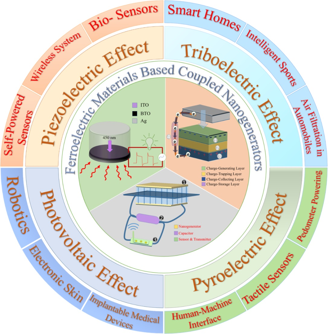
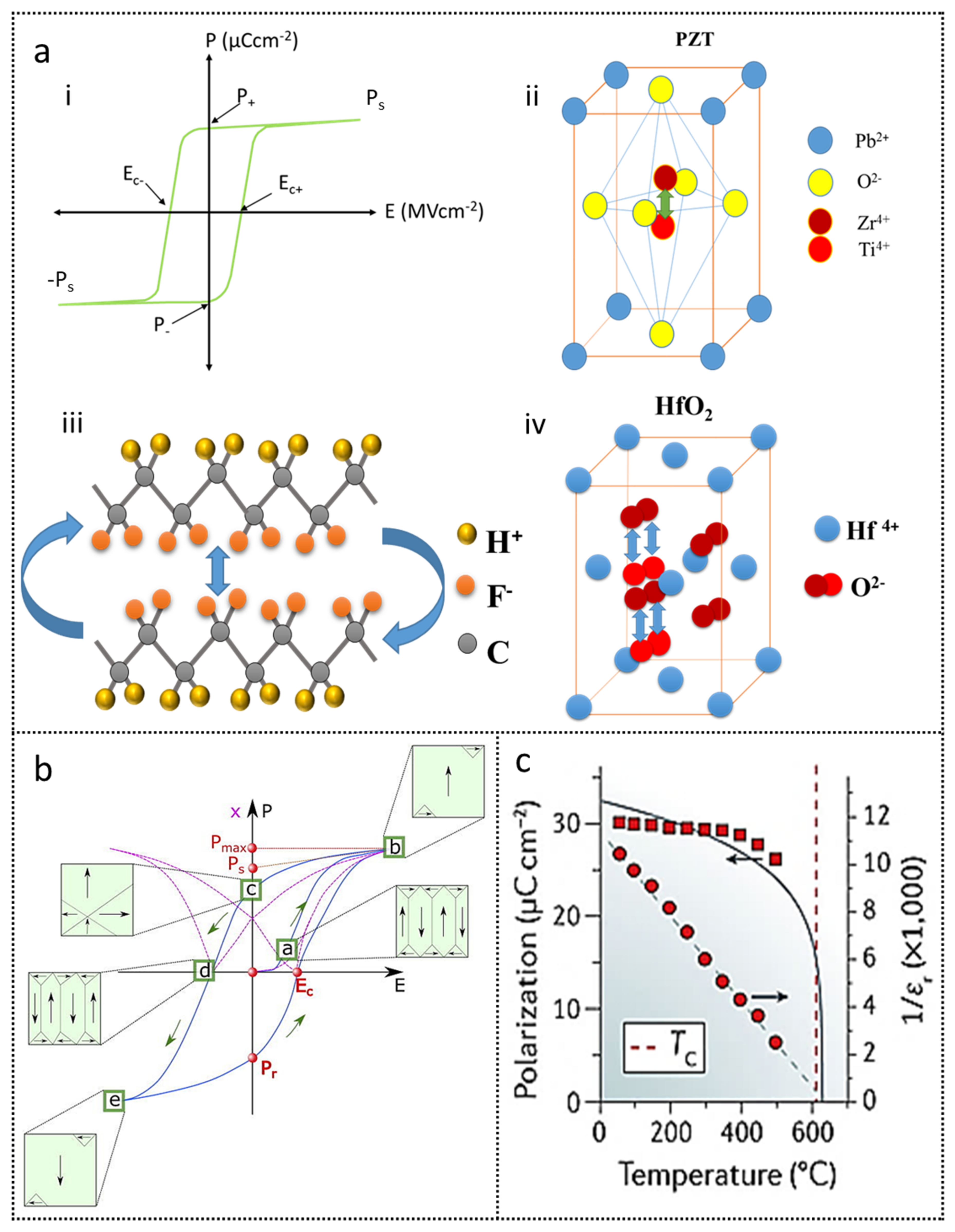
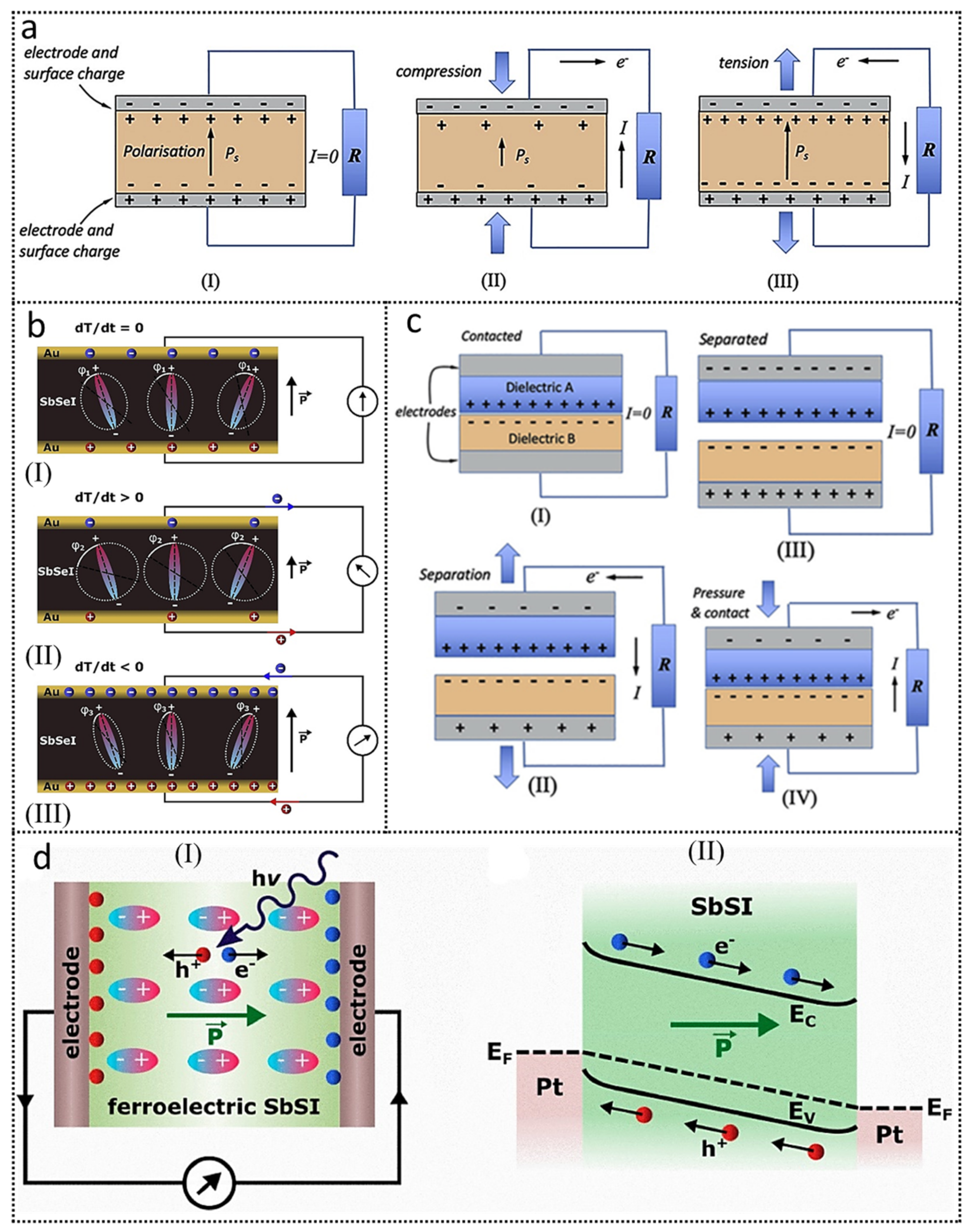
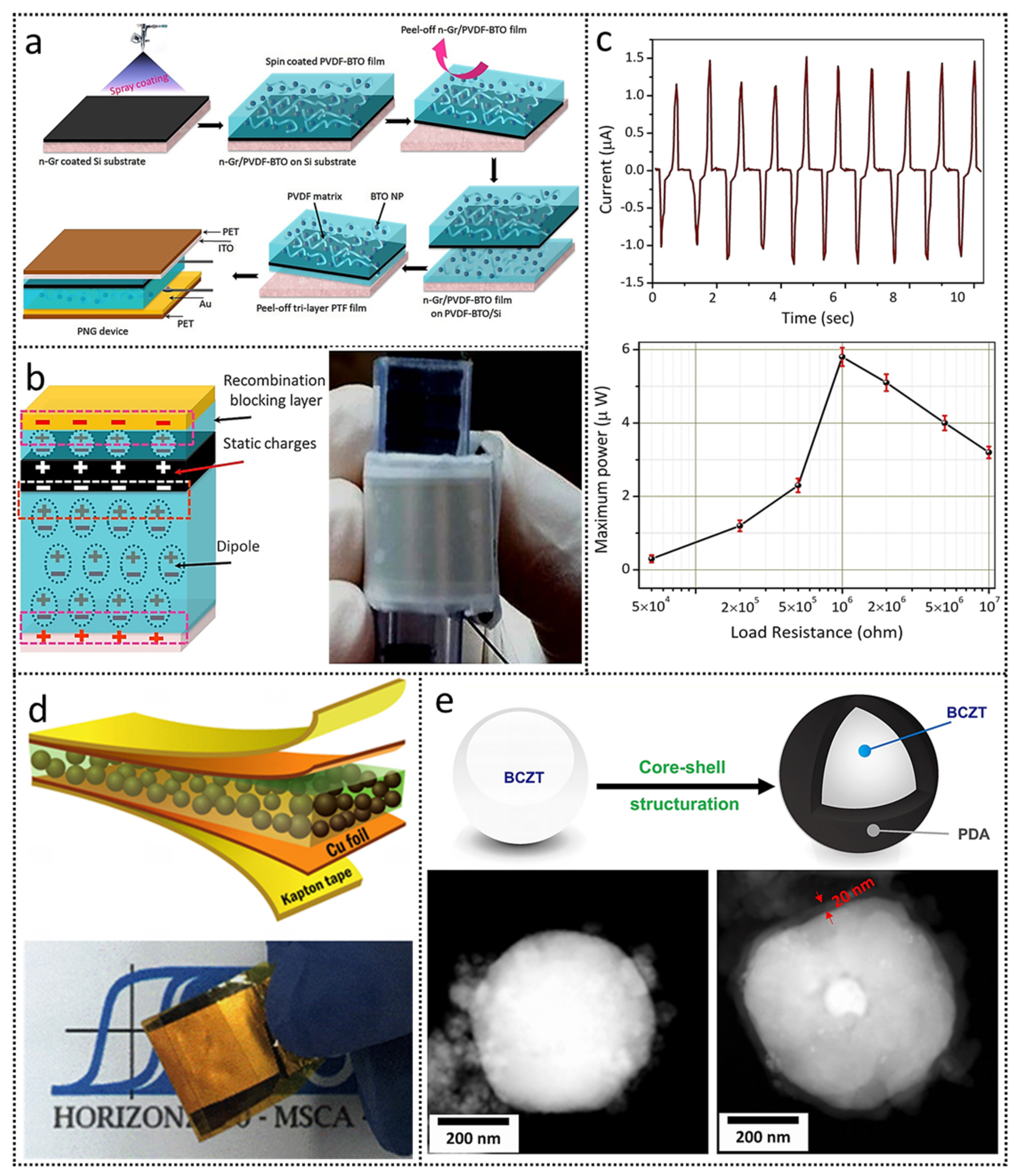
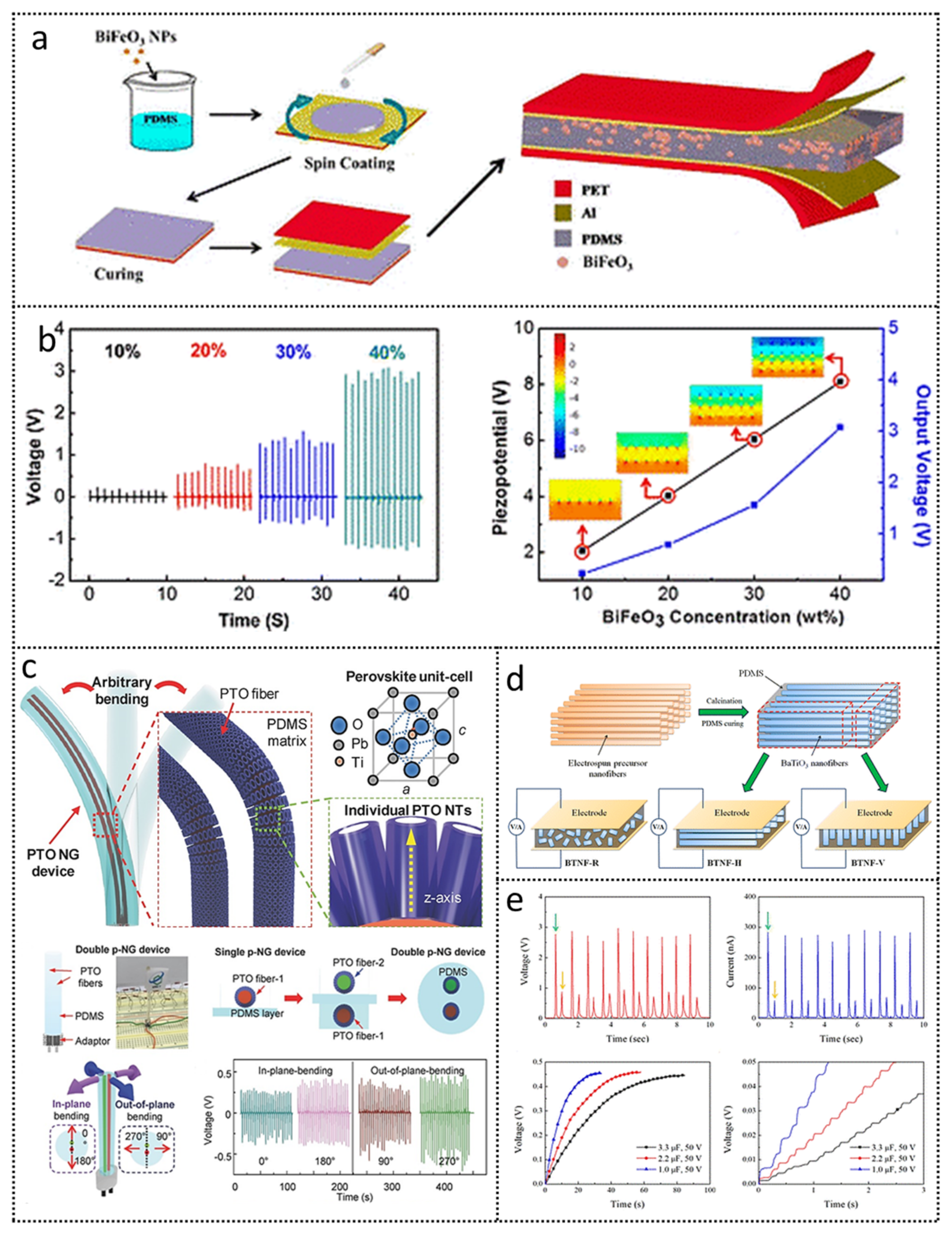
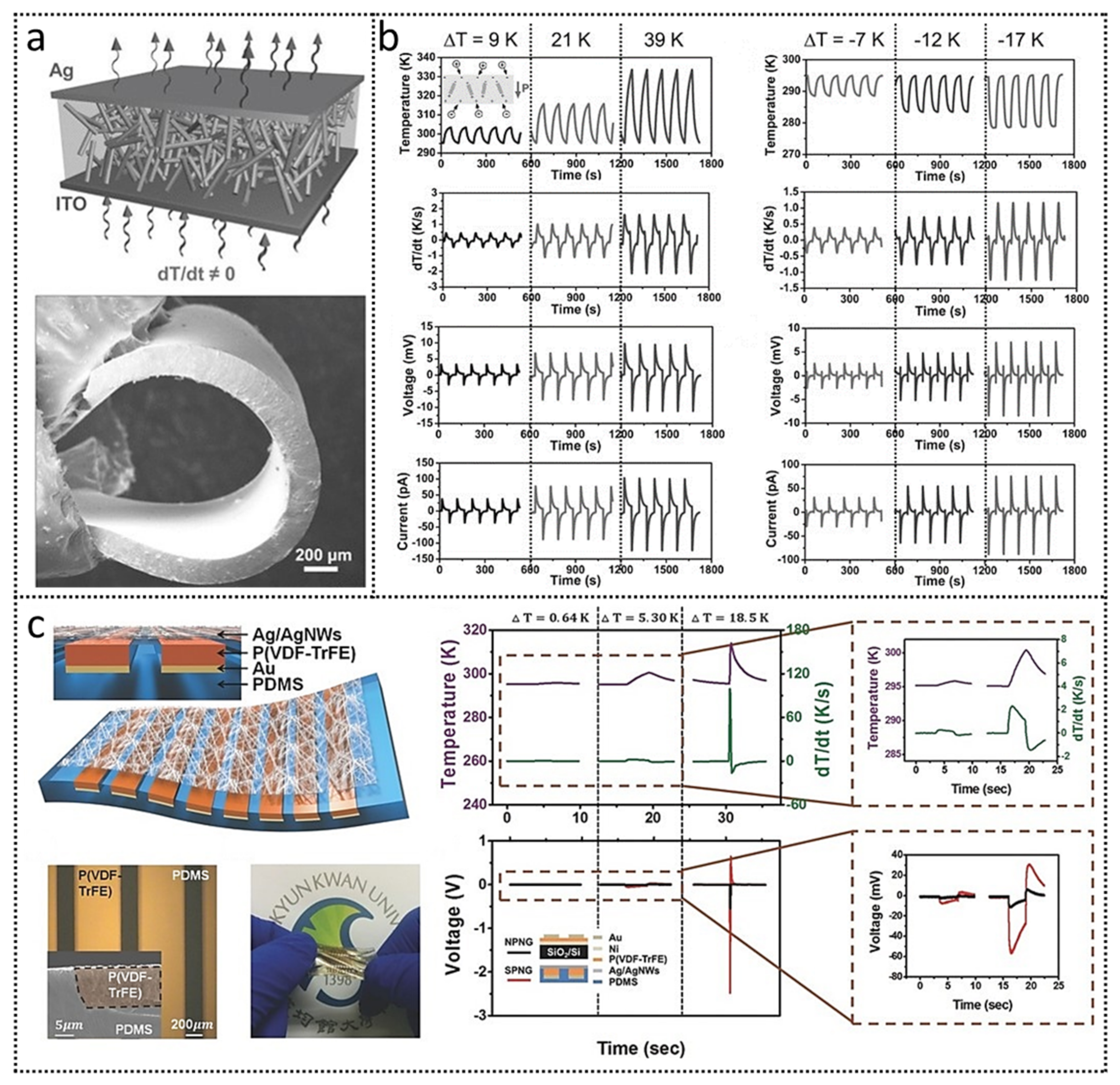
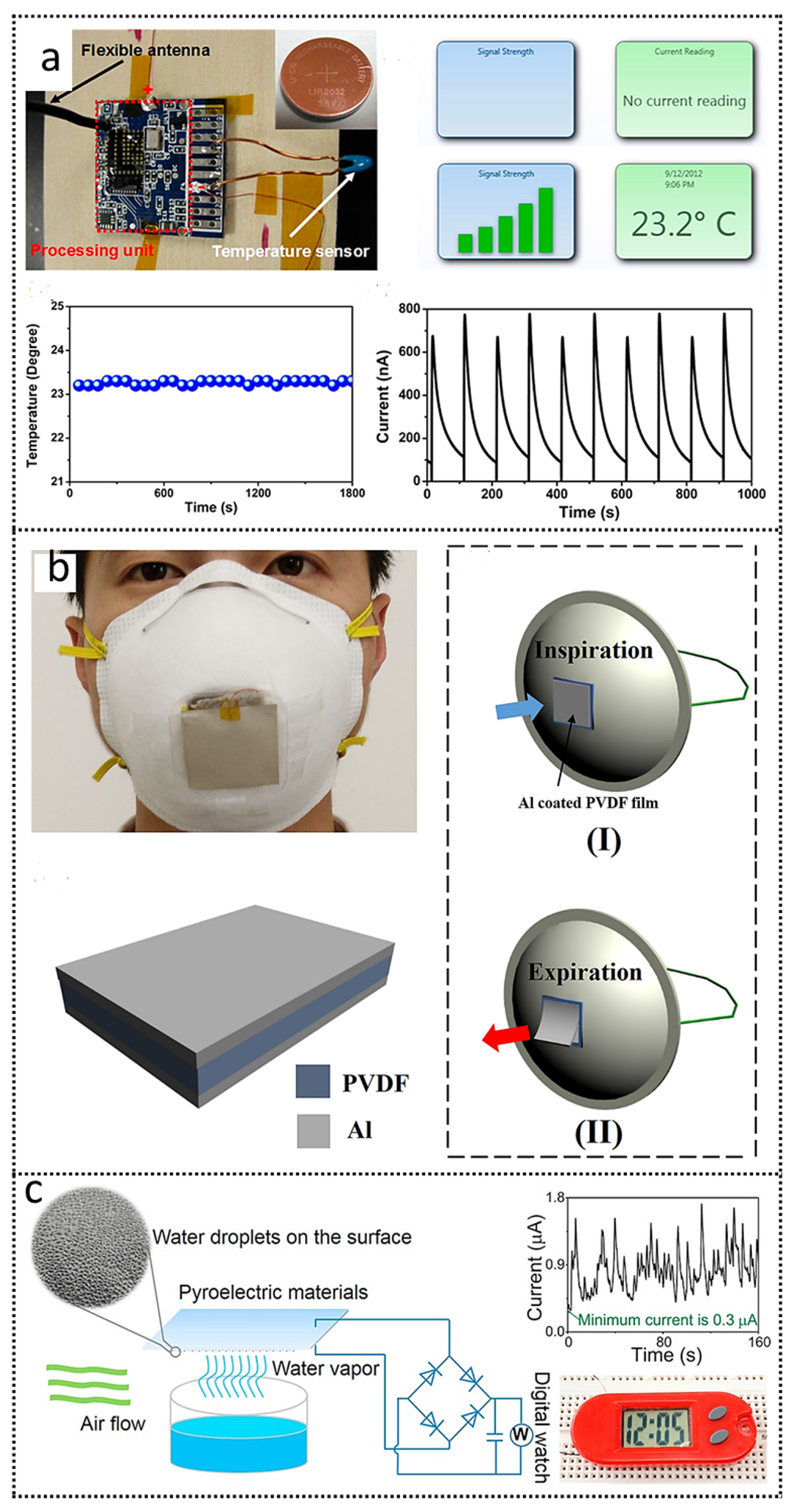
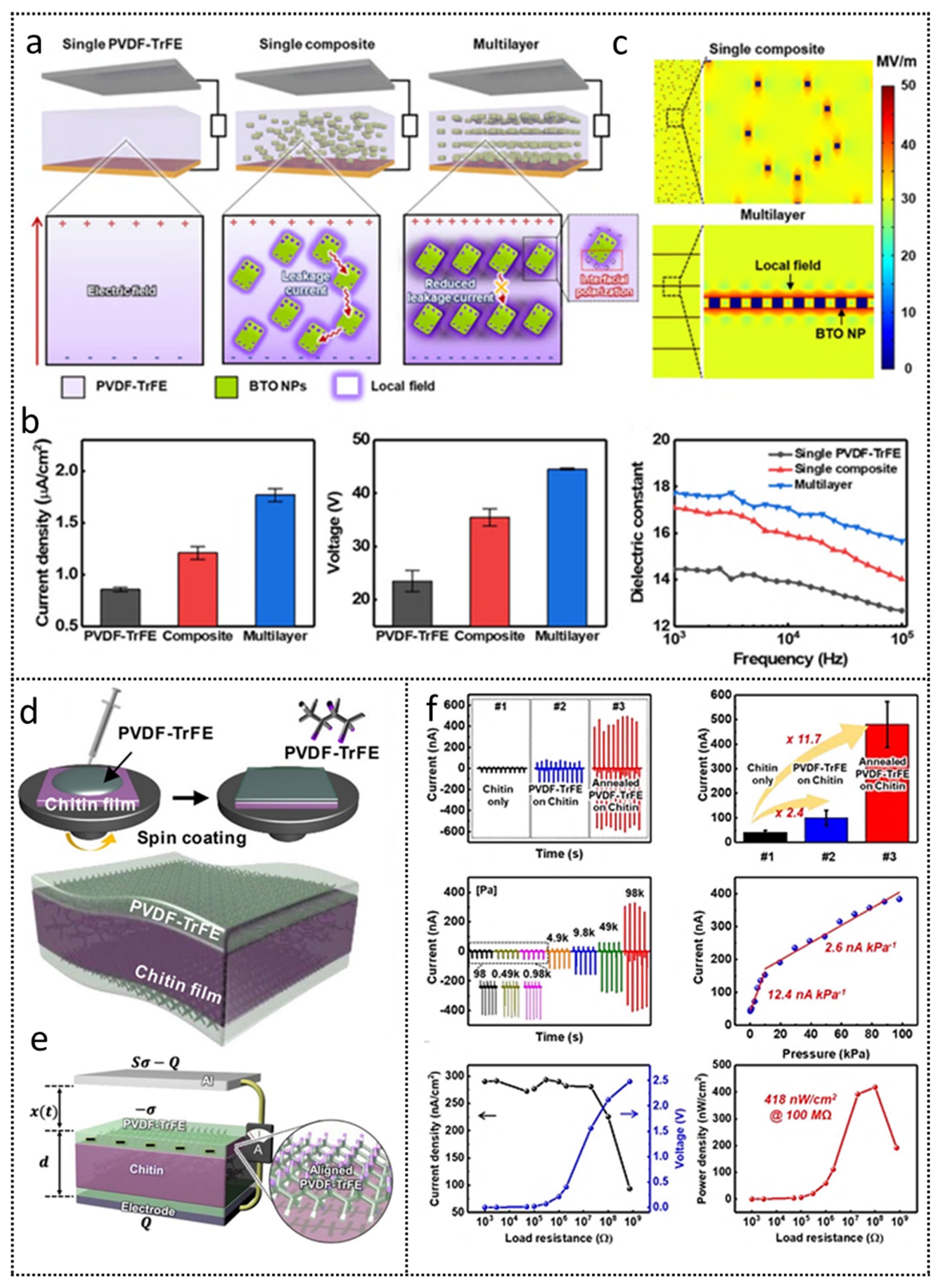
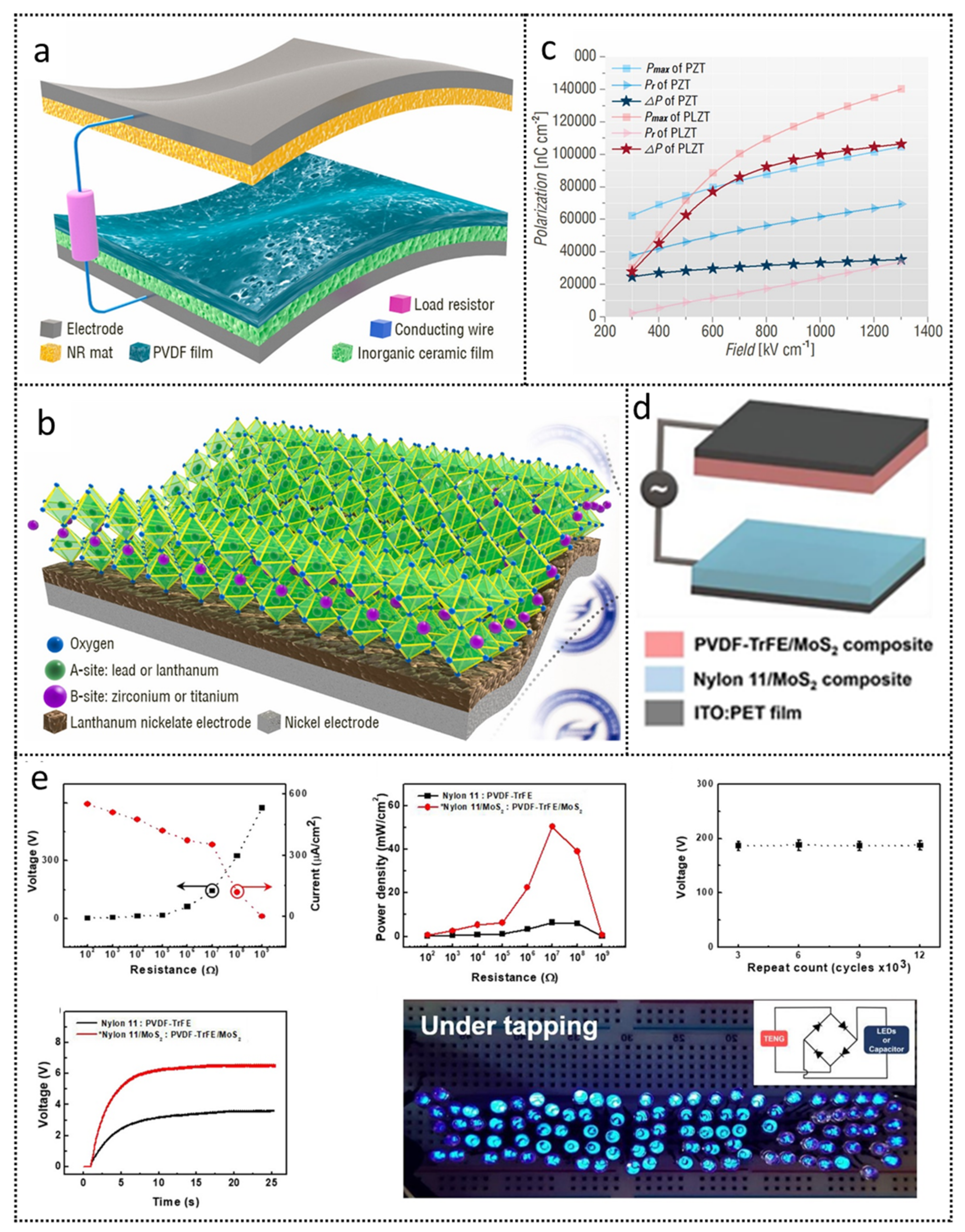
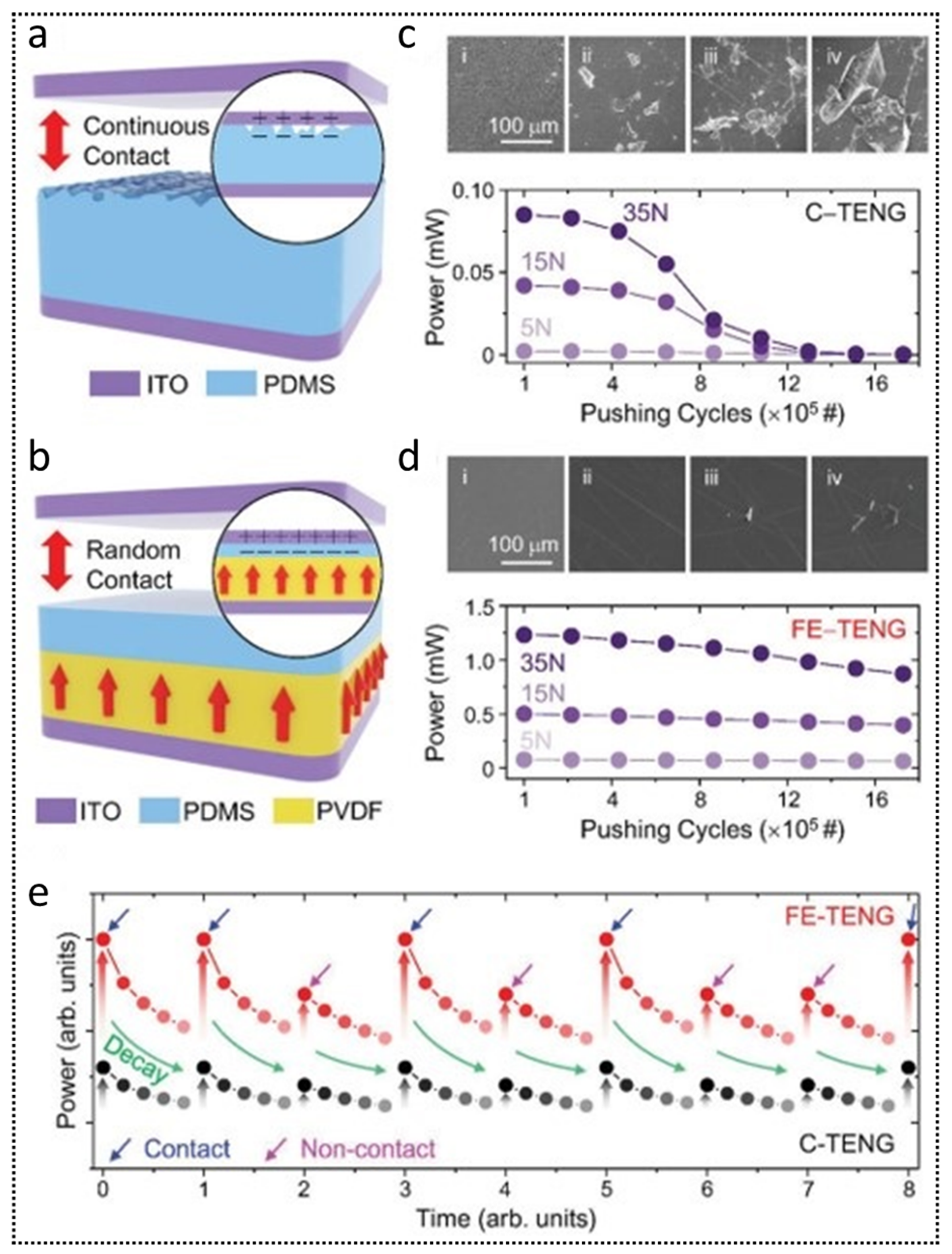
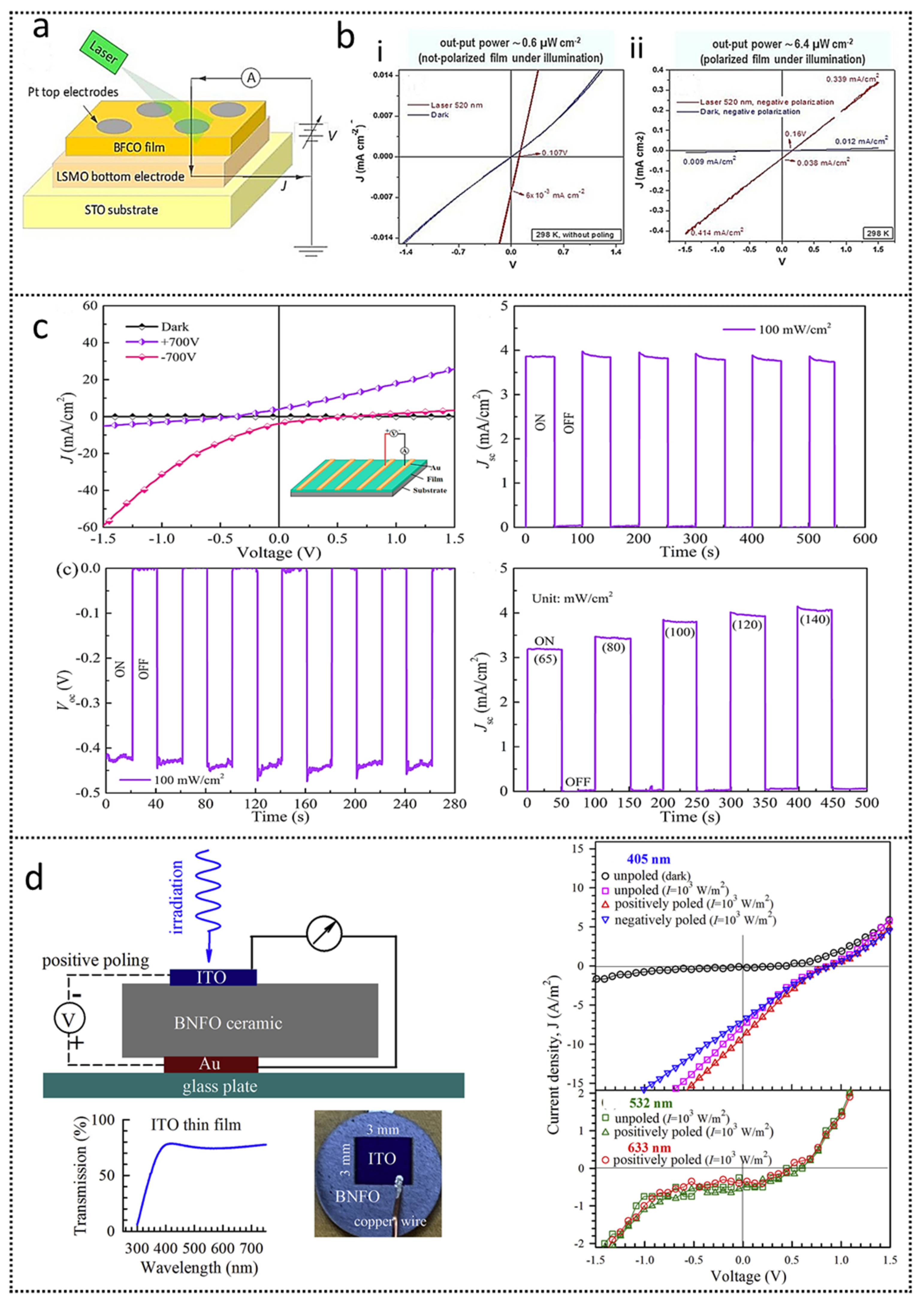
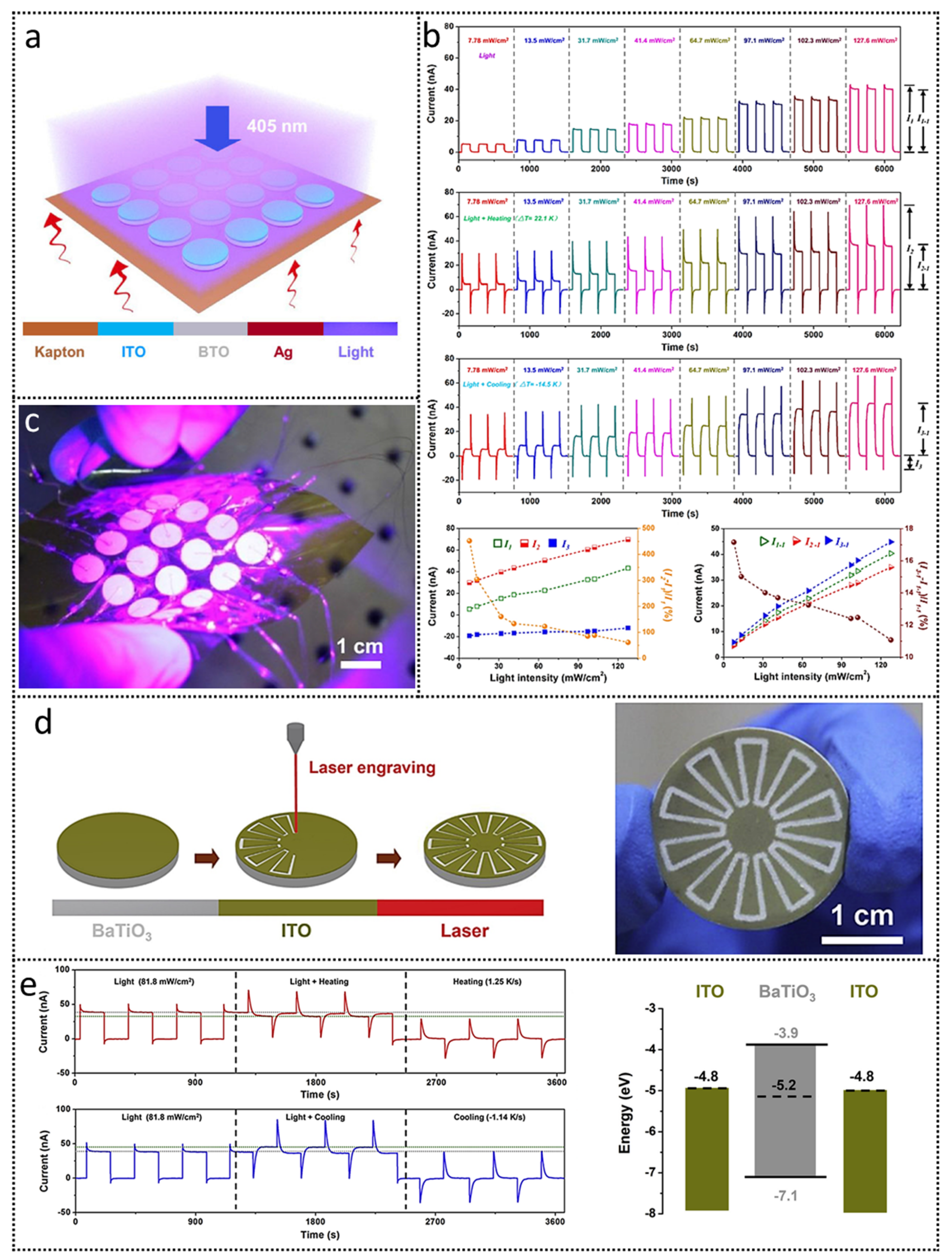
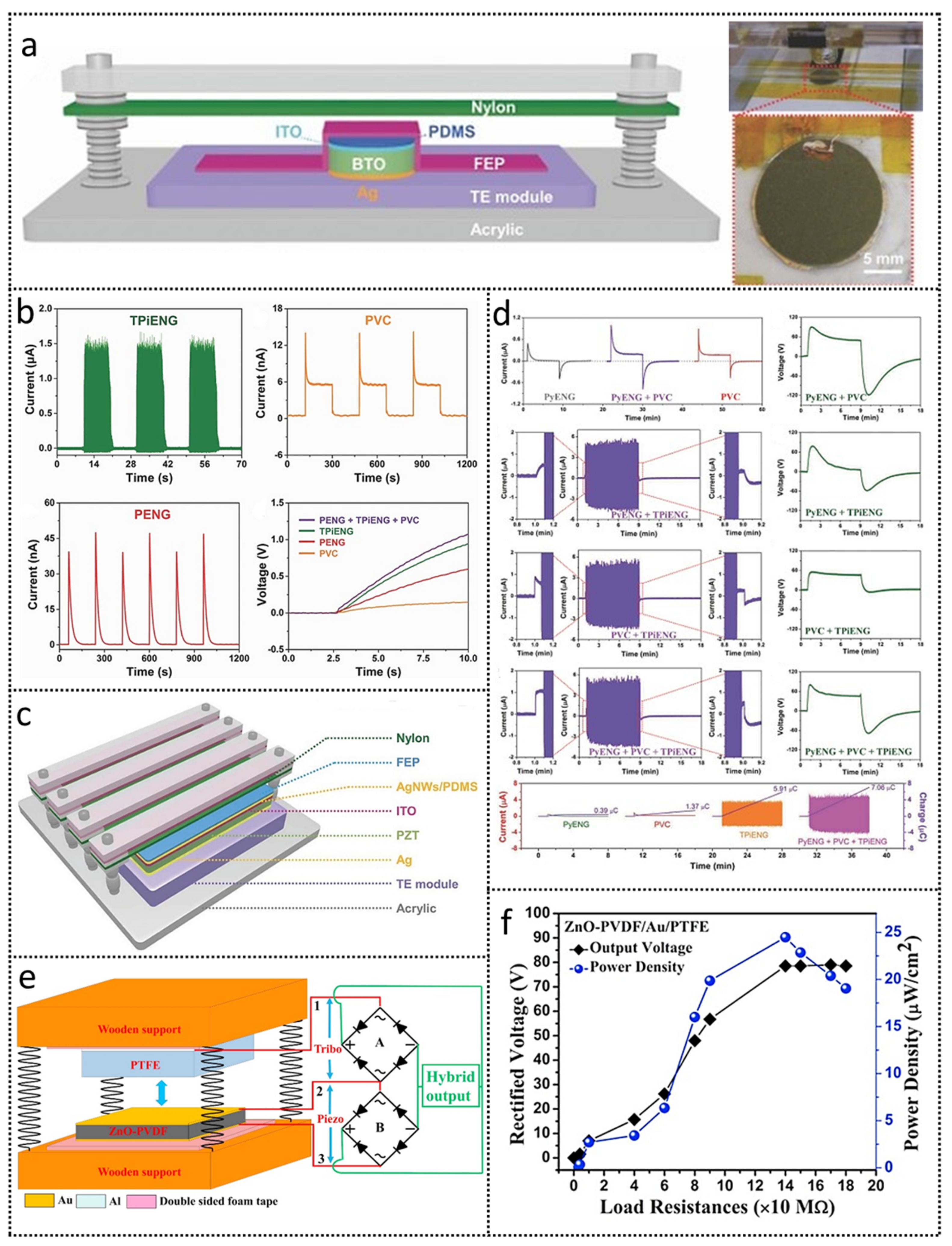
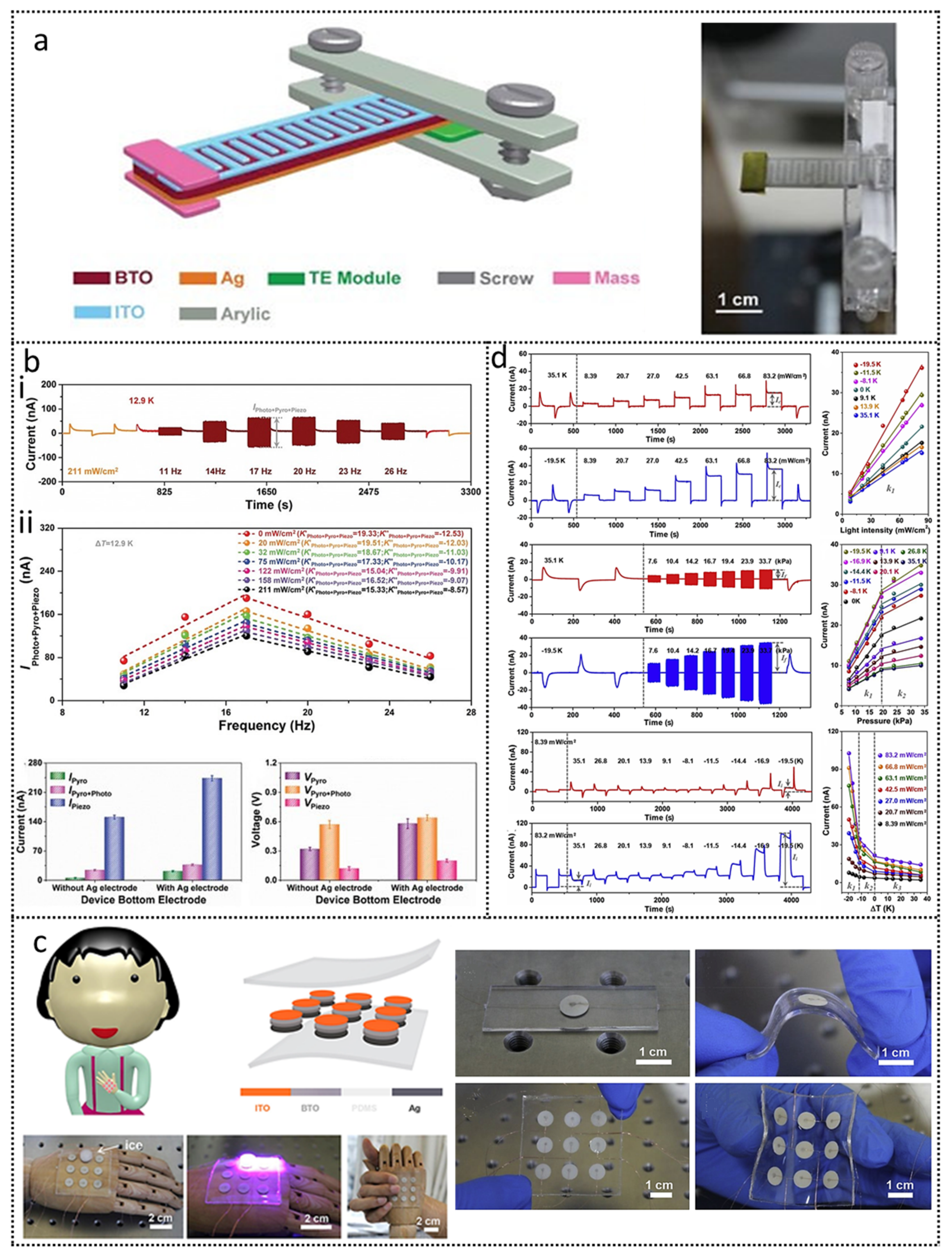
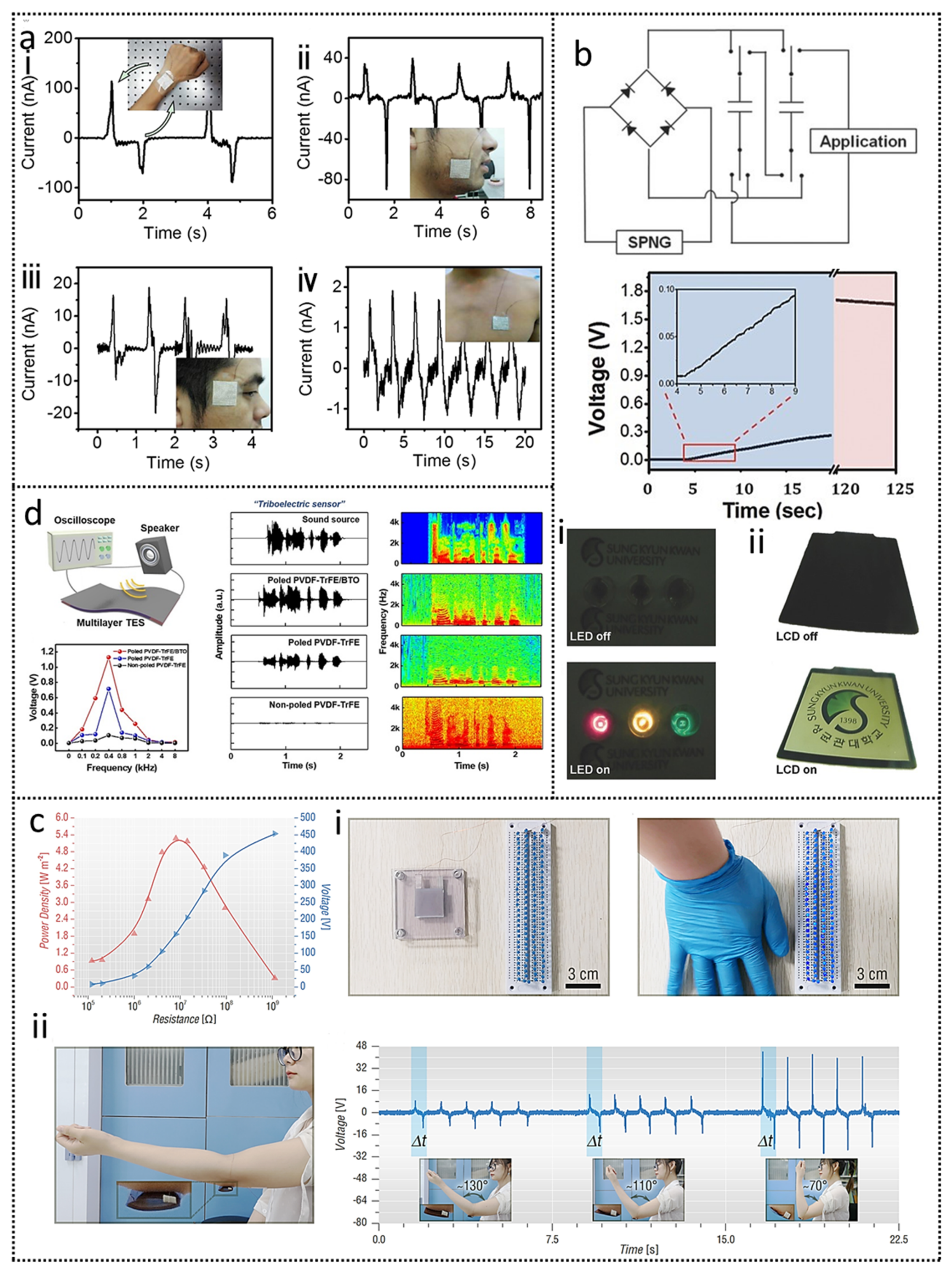
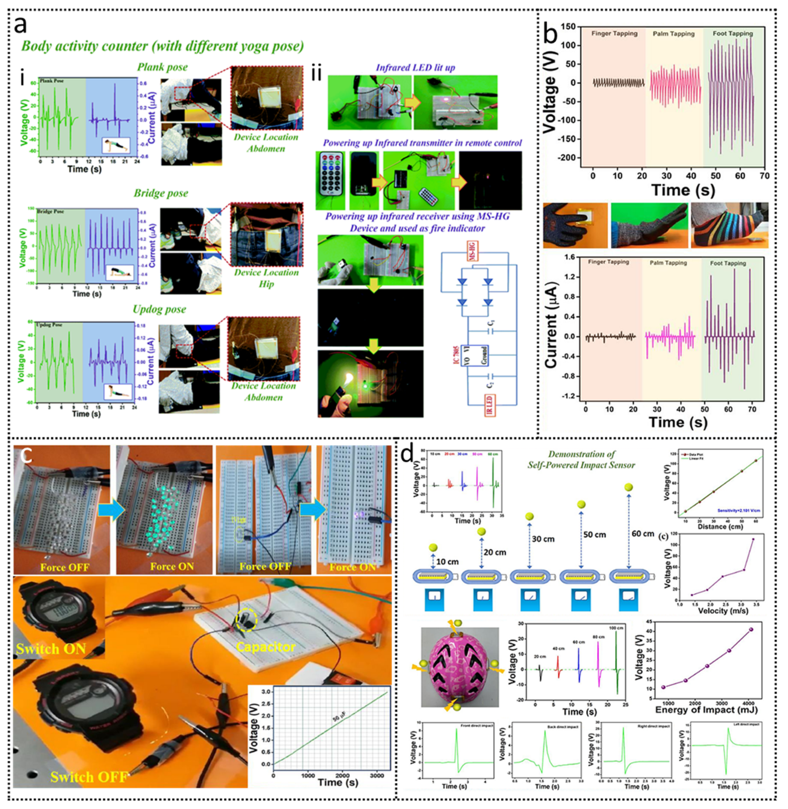
Table 1.
Piezoelectric nanogenerators, based on ferroelectric materials, for energy harvesting.
| Material Name | Open-Circuit Voltage Voc | Short-Circuit Current Isc | Short-Circuit Current Density Jsc | Maximum Area Power Density | Maximum Power | Work Conditions | Reference |
|---|---|---|---|---|---|---|---|
| PVDF/SM-KNN (3%) | 21 V | 22 μA | 5.5 μA/cm2 | 115.5 μW/cm2 | - | 1.1 kPa pressure | [34] |
| Ag/(K, Na)NbO3 | 240 V | 23 μA | - | - | 1.13 mW | 0.1 MPa mechanical stress | [176] |
| FAPbBr3@PVDF | 30 V | - | 6.2 μA/cm2 | 27.4 μW/cm2 | - | 0.5 MPa mechanical stress | [177] |
| BaTiO3/PDMS | 5.5 V | 350 nA | 350 nA/cm2 | - | - | 1 MPa mechanical stress | [23] |
| PVDF-TrFE/SnS nanosheets | 17.28 V | - | 0.94 μA/cm2 | 10.69 μW/cm2 | - | 0.5 MPa pressure | [178] |
| rGO/PVDF nanofiber mat | 16 V | 700 μA | - | - | 7.4 μW | Finger press | [179] |
| BaTiO3@PVDF | 6 V | 1.5 μA | - | 8.7 mW/cm2 | - | Impact force of 700 N with frequency 1–3 Hz | [180] |
| Pb0.67Zr0.33TiO3/ PDMS | 152 V | 17.5 μA | - | - | 1.1 mW | 100 N stress force | [75] |
| P(VDF-TrFE)/GeSe nanosheets | 17.58 V | - | 1.14 μA/cm2 | 9.76 μW/cm2 | - | 0.5 MPa pressure | [181] |
| 0.5Ba(Zr0.2Ti0.8)O3-0.5(Ba0.7Ca0.3)TiO3/ PVDF-TrFE | 13.01 V | - | - | - | 1.46 μW | Cyclic tapping of 6 N and 10 Hz | [182] |
| 0.94(Bi0.5Na0.5)TiO3-0.06BaTiO3 (NBT-BT)/PVDF | 9 V | 8–9 μA | - | - | 80 μW | 250 N impact force | [183] |
| Ba(Ti0.88Sn0.12)O3-GFF/PVDF | 26.9 V | 597 nA | - | - | - | 5 N impact force | [184] |
Table 2.
Pyroelectric nanogenerators, based on various ferroelectric materials.
| Material Name | Output Characteristics | Pyroelectric Coefficient p | Operating Conditions ΔT, dT/dt | Maximum Power/Power Density | Energy Density | Reference |
|---|---|---|---|---|---|---|
| 0.7Pb(Mg1/2Nb2/3)O3-PbTiO3 | Voc: 1.1 V Isc: 10 nA | 104 nC/cm2K; 300 K 235 nC/cm2K; 370 K | (300 to 370 K) 0.5 K/s | - | - | [190] |
| 0.94Na0.5Bi0.5TiO3-0.06BaZr0.2Ti0.8O3 (NBT-BZT): xSiO2 | Voc: 3.5 V Isc: 90 nA | 20 × 10−4 C/m2K | 25 °C to 50 °C | - | 110 μJ/cm3 | [191] |
| (1-x)(0.98Bi0.5Na0.5TiO3-0.02BiAlO3)-x(Na0.5K0.5)NbO3 | Voc: 3.3 V Isc: 81.5 nA | 8.04 × 10⁻⁴ C/m2K | 25 °C to 50 °C and 3 °C/s | - | 23.32 μJ/cm3 | [192] |
| PVDF | Voc:192 V Isc: 12 μA | 2.7 nC/cm2K | 60 °C to 80 °C | 14 μW | - | [129] |
| PVDF/GO | Voc: 60 mV Isc: 45 pA | 27 nC/m2K | ΔT = 20 °C and 2.12 K/s | 1.2 nW/m2 | - | [193] |
| PMnN-PMS-PZT (Zr/Ti:95/5) | Voc: 25.3 V | 5957 μC/m2K | 18 °C to 65 °C and 3.15 °C/s | 25.7 μW | - | [194] |
| 0.68PMN-0.32PTO | Isc: 90 nA | −550 μC/m2K | Temperature oscillations of 10 K | 526 W/cm3 | 1.06 μJ/cm3 | [195] |
Table 3.
Triboelectric nanogenerators, based on various ferroelectric materials.
| Material Pair | TENG Mode | Short-Circuit Current Isc/Current Density Jsc | Open-Circuit Voltage Voc | Maximum Power/Power Density | Work Function | Work Conditions | Reference |
|---|---|---|---|---|---|---|---|
| BTO/FEP | CS-mode | 100 μA | 1000 V | 67 mW | - | 14 m/s wind energy | [40] |
| ZnO-PVDF@PTFE | FL | 1.6 μA | 119 V | 10.6 μW/cm2 | 4.57 eV | [203] | |
| Al-NR@PVDF-PI/(NBT-15ST(60))-Al | CS | 32.5 μA/cm2 | 1020 V | - | - | Instantaneous force of 50 N | [55] |
| PVDF-NaNbO3 | CS | 3.98 μA | 181 V | 0.17 mW | 4.0 eV | [210] | |
| PZT/GFF | SL | 59.05 mA/m2 | 1640 V | 10.8 W/m2 | - | 10 N, 4 Hz | [211] |
| PDMS/PVDF | CS | 22 μA | 255 V | 832.05 mW/m2 | - | 0.5 Hz | [212] |
| BFO-GFF/PDMS | CS | 3.67 μA/cm2 | 115.22 V | 151.42 μW/cm2 | - | 1 Hz | [57] |
| BTO-PTFE | CS | 10.4 μA/cm2 | 45 V | - | - | 50 N, 2 Hz | [46] |
| PVDF-TrFE/Mxene | CS | 140 mA/m2 | 270 V | 4.02 W/m2 | - | 7 N, 6 Hz | [121] |
| PI/PVDF-TrFE | CS | 17.2 μA | 364 V | 2.56 W/m2 | - | 2 Hz | [213] |
Table 4.
Output performances of some ferroelectric photovoltaic devices.
| Material | Short-Circuit Current Isc, Current Density Jsc | Open-Circuit Voltage Voc | Work Condition | Responsivity (R)/ Detectivity (D)/ Gain (G) | Output Power | PCE (%) | Eg (eV) | Reference |
|---|---|---|---|---|---|---|---|---|
| Bi0.98Ca0.02Fe0.95Mn0.05O3 (BCMFO) | 0.26 mA | −0.92 V | white light (280 mW/cm2) | - | - | 0.0075 | Eg = 2.41 eV 4.82 eV | [233] |
| NiO/BaTiO3/ZnO | 2.2 × 10⁻² A | 254 nm UVC, 5.57 mW 100 °C | R = 3.98 A/W D = 3 × 10⁹ nHz1/2/W G = 19.4 | - | 1 | - | [234] | |
| BaTiO3 nanoparticles | 393.1 nA | - | 405 nm, 131.0 mW/cm280–240 K | R = 1.46 × 10⁻⁶ A/W D = 1.59 × 10⁷ jones G = 4.46 × 10⁻⁶ | 8.02 nW | - | = 5.3 eV | [43] |
| CsPbBr3 nanowires | - | 3 V | 405 nm, 0.2 mW/cm2 | R = 4.4 × 10³ A/WG = 1.3 × 10⁴ | - | - | - | [39] |
| K0.49Na0.49Ba0.02 (Nb0.99Ni0.01)O2.995 | 0.03 μA/cm2 | 0.11 V | 405 nm laser, 50 mW | - | 60 μW | 0.12 | - | [223] |
| SbSeI nanowires | 0.36 pA 0.0074 μA/cm2 | 97 mV | 488 nm Ar laser, 127 mW/cm2 | - | 0.119 nW | - | Eg = 1.862 eV | [29] |
| ZnO/Bi5FeTi3O15 | 2.2 mA/cm2 | 0.15 V | 405 nm, 200 mW/cm2 | - | 0.09 mW/cm2 | - | Eg = 3.08 eV = 4.86 eV | [235] |
| Bi6Fe1.6Co0.2Ni0.2 Ti3O15/Bi2FeCrO6 | 10.3 mA/cm2 | 0.66 V | AM 1.5G illumination | - | - | 3.40 | Eg = 1.62 eV/1.74 eV | [236] |
| NiO/BFCrO/WS2 | 1.80 mA/cm2 | 0.78 V | 1 sun illumination | - | - | 7.07 | - | [237] |
| Sm:BiFeO3 | 0.58 nA/cm2 | 0.90 V | Xenon lamp (100 mW/cm2) | - | - | 1.65 | - | [238] |
Publisher’s Note: MDPI stays neutral with regard to jurisdictional claims in published maps and institutional affiliations. |
© 2021 by the authors. Licensee MDPI, Basel, Switzerland. This article is an open access article distributed under the terms and conditions of the Creative Commons Attribution (CC BY) license (https://creativecommons.org/licenses/by/4.0/).
Share and Cite
MDPI and ACS Style
Minhas, J.Z.; Hasan, M.A.M.; Yang, Y. Ferroelectric Materials Based Coupled Nanogenerators. Nanoenergy Adv. 2021, 1, 131-180. https://0-doi-org.brum.beds.ac.uk/10.3390/nanoenergyadv1020007
AMA Style
Minhas JZ, Hasan MAM, Yang Y. Ferroelectric Materials Based Coupled Nanogenerators. Nanoenergy Advances. 2021; 1(2):131-180. https://0-doi-org.brum.beds.ac.uk/10.3390/nanoenergyadv1020007
Chicago/Turabian StyleMinhas, Jabir Zamir, Md Al Mahadi Hasan, and Ya Yang. 2021. "Ferroelectric Materials Based Coupled Nanogenerators" Nanoenergy Advances 1, no. 2: 131-180. https://0-doi-org.brum.beds.ac.uk/10.3390/nanoenergyadv1020007