Article

Comparative Biomechanical Study of Screw Fixation Techniques in Periacetabular Osteotomy

by
Mahsan Bakhtiarinejad
1,2,*,
Amirhossein Farvardin
1,2,
Ryan J. Murphy
1,2,
Robert B. Grupp
2,3,
John E. Tis
4,
Paul D. Sponseller
4 and
Mehran Armand
1,2,4
1
Department of Mechanical Engineering, Johns Hopkins University, Baltimore, MD 21218, USA
2
Laboratory for Computational, Laboratory for Biomechanical and Image-Guided Surgical Systems (BIGSS), Baltimore, MD 21218, USA
3
Department of Computer Science, Johns Hopkins University, Baltimore, MD 21218, USA
4
Department of Orthopedic Surgery, Johns Hopkins Medicine, Baltimore, MD 21287, USA
*
Author to whom correspondence should be addressed.
Submission received: 12 April 2021 / Revised: 30 April 2021 / Accepted: 6 May 2021 / Published: 17 May 2021

Abstract

:
Periacetabular osteotomy (PAO) is a common surgical treatment for developmental dysplasia of the hip. To obtain the optimal method of fixation during PAO, different screw fixation techniques have been proposed for stabilizing the acetabular fragment. This study assesses the biomechanical performance of two popular 3-screw fixation techniques: iliac (IS) and transverse (IT) configurations, through finite element simulations. Additionally, different 2-screw combinations are simulated to investigate the biomechanical significance of each screw of the fixation configurations. The study findings show that yield load of the pelvic bone subject to gait loading for IT configuration is on average 7% higher compared to that of the IS. Although the yield load of the IT is predicted to be slightly higher, no significant difference in bone stiffness and displacement of the acetabular fragment are found between two configurations. Simulation results, therefore, do not demonstrate a significant biomechanical advantage of the IT configuration over the IS. Furthermore, the biomechanical comparison between the 2-screw combinations of IS and IT fixations demonstrates that the most anterior screw in IS, located at the iliac crest, and the most medial screw in the IT are the most critical elements in providing sufficient stability and support for acetabular fragment.

1. Introduction

Developmental dysplasia of the hip (DDH) is a congenital condition in which the acetabulum or femoral head is deformed, which results in incongruency between the femoral head and the acetabular cartilage. If not treated, DDH can lead to early severe osteoarthritis of the hip joint [1]. Periacetabular Osteotomy (PAO), which preserves and improves the function of the patient’s own hip, has shown to be an effective treatment option for patients with DDH [2]. PAO aims to reduce or eliminate pain by improving the biomechanics of the hip joint and reducing the high stresses that cause damage and arthritis. For this purpose, the acetabulum is cut around the hip joint and reoriented to improve the acetabular joint coverage, and in theory reduce the peak contact pressure on the lateral edge of the acetabulum [2].
Since introduction of the technique, several studies have aimed to analyze and improve the biomechanical outcomes of the procedure utilizing computer aided interventions and finite element (FE) computational models [3,4,5,6,7,8,9,10,11]. Positioning the acetabular fragment during PAO has its own challenges; therefore, a Biomechanical Guidance System (BGS) was developed to evaluate the femoral head coverage and guide the surgeons in real-time [5]. The BGS estimates the contact pressure through Discrete Element Analysis (DEA), an analysis capable of estimating the location and magnitude of the peak contact pressure faster but with a comparable accuracy to those of FE analysis [12,13].
Despite the promising clinical outcomes of the procedure [14], fixation of acetabular fragment after repositioning remains a challenge. Considering reports of nonunion, postoperative loss of correction and fragment migration, it is difficult to achieve the fixation stability after PAO [15,16,17,18,19]. Few studies have compared the biomechanical strength and stability of different fixation techniques through in vitro experiments [16,17,20]. Two of the most common fixation techniques are: (1) iliac fixation (IS), in which three 4.5-mm cortical screws (Figure 1) in the length range of 80 to 120 mm are inserted from the iliac crest to the osteotomized fragment and (2) transverse fixation (IT) where two such screws are inserted from the iliac crest to the osteotomized fragment, and the third screw is inserted transversely from the acetabular segment to the ilium [16]. In the study of Babis et al. (2002), the transverse screw construct was distinguished to be a more stable and stiffer fixation with a lower displacement of the pubic osteotomy (2002). In the study of Yassir et al. (2005), multiple screw configurations were tested against axial cyclic loading, and small amounts of displacement (<2 mm) and angular rotation (<3 degrees) relative to the pelvic coordinates were encountered for each fixation technique.
The objective of this study is to investigate the biomechanical performance of each fixation method in providing joint stability after PAO, with the aid of FE analysis that would assist the surgeons in assessing the advantages of each method. For this purpose, we develop subject-specific computational models of the pelvic bone, along with IS and IT fixation screws and compare the fixation techniques through the prediction of bone stiffness and yield load, peak von Mises stress and compressive strain of both acetabular and pelvic osteotomized fragments and maximum normal and shear stresses of the fixation screws. Furthermore, we investigate the biomechanical significance and contribution of each fixation screw in creating the adequate compression, thereby stabilizing the acetabular fragment through biomechanical simulations of pelvic bone fixated by two screws in different combinations of IS and IT layouts.

2. Materials and Methods

2.1. Geometrical Modeling

We first generate 3D models of the pelvis from segmented preoperative Computed Tomography (CT) scans of two dysplastic patient models. The first patient model weighs 51 kg, with PAO performed on the left side of the pelvis. The second model weighs 87 kg, with PAO performed on the right side. CT scans were acquired on a PQ2000 (Picker International, Inc, Highland Heights, OH, USA.) with slice thickness of less than 4 mm, which is resampled to 1 mm. The spacing between slices were less than 2 mm. Through a threshold-based segmentation of the bony anatomy and manual refinement, the pelvic bone region is identified and a 3D pelvis model is generated using commercial image processing software (Amira, Visualization Sciences Group, Burlington, MA, USA) [21,22]. Considering the PAO procedure on detaching the hip socket, we create the acetabular fragment through a custom-built module in 3D Slicer software [23]. For this purpose, we first define three cutting planes from anterior to posterior ilium and ischium, and from superior to inferior pubis, to create mirror-like osteotomies on both sides of the pelvis and then reorient the acetabular fragment. Using SolidWorks (Dassault Systèmes SolidWorks Corporation, Waltham, MA, USA) software, we place the iliac screws approximately 1 cm from the Anterior Superior Iliac Spine (ASIS) and 1 cm apart from each other. In the IT screw configuration, two iliac screws are placed approximately 1.5 cm from the ASIS and 2 cm apart. The transverse screw is extended from the anterior inferior iliac spine into the sciatic buttress. Based on the anatomy of the pelvic bone and surgeon’s accessibility, the lengths of the screws that attach the acetabular and pelvic osteotomized fragments are varied. Starting from the ASIS, three IS screws are inserted with the length of 95, 110 and 110 mm for the first model and 90, 100 and 105 mm for the second model (Figure 1). Starting from the ASIS, two IT screws are 100 and 110 mm, and the transverse screw is 85 mm for the first model, and they are 95, 105 and 92 mm for the second model, respectively. We also create five 2-screw configurations by removing individual screws in succession for both IS and IT fixations of the first model, as shown in Figure 1. In the IT group, the transverse screw is kept untouched and two screws in the iliac crest were removed sequentially.

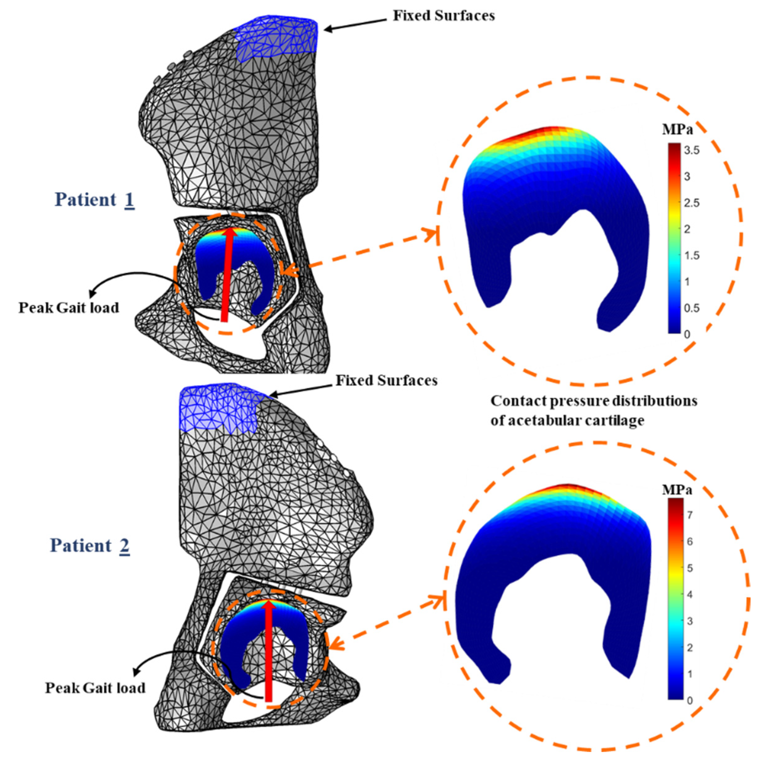
2.2. Finite Element Simulation
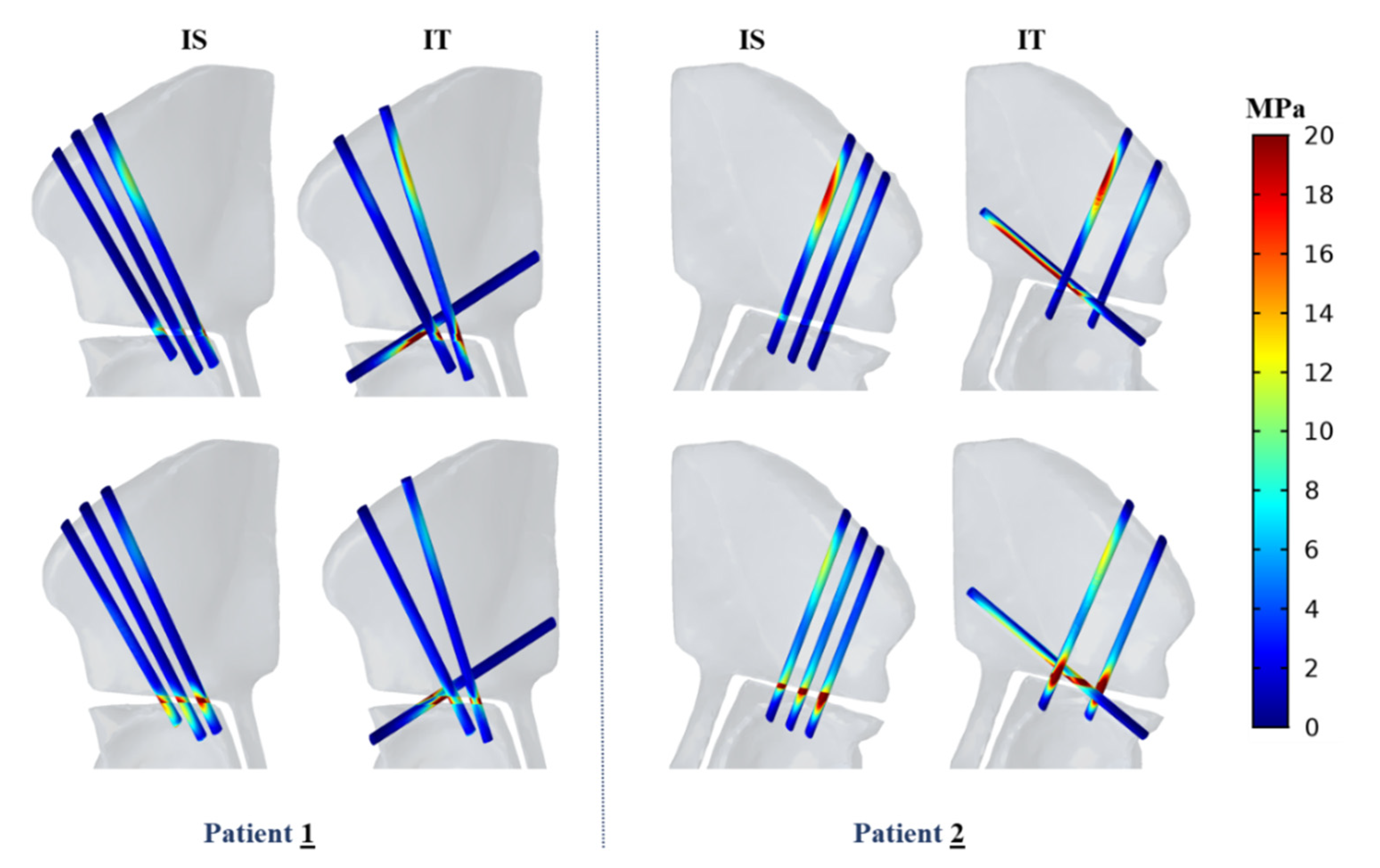
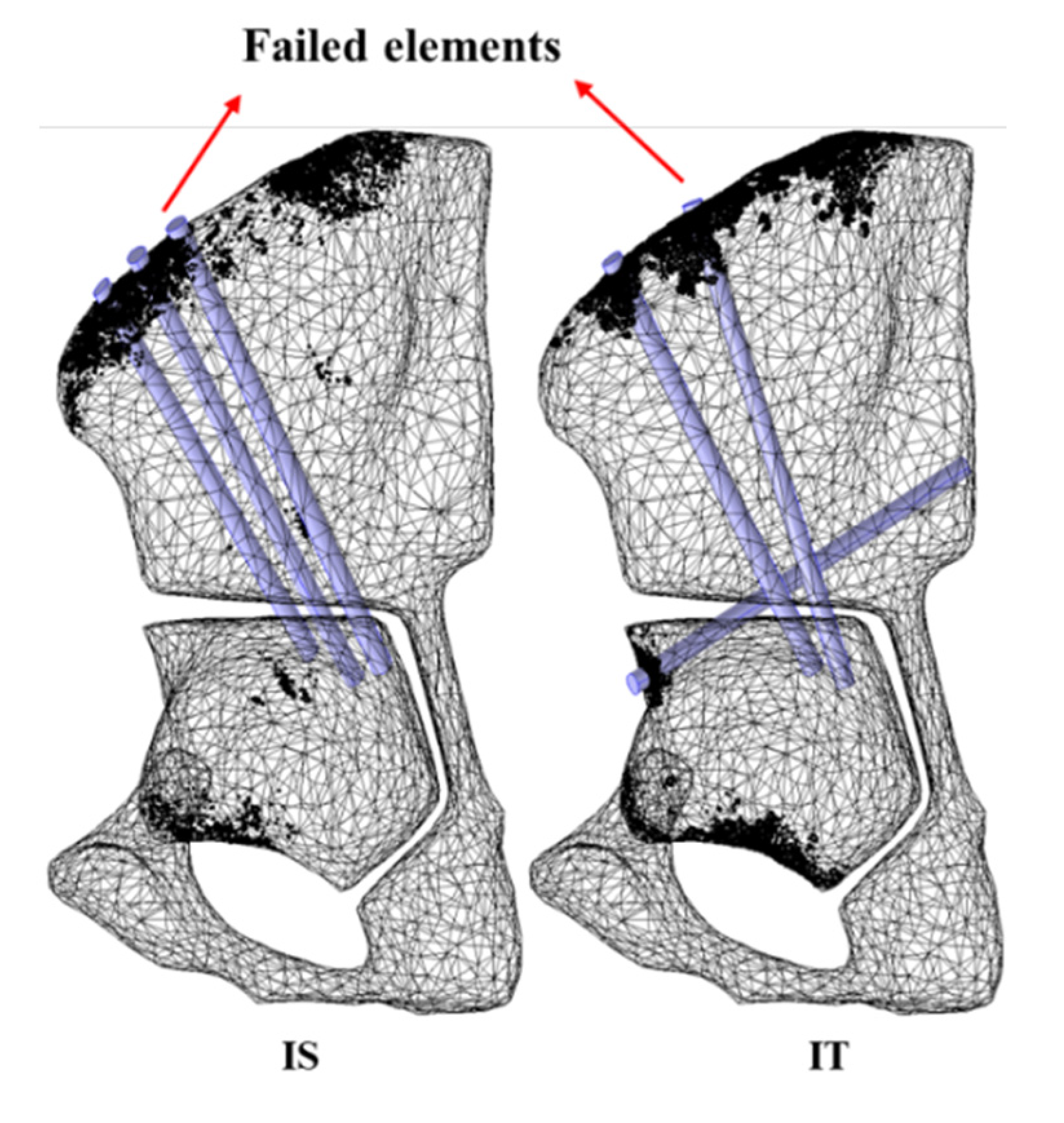
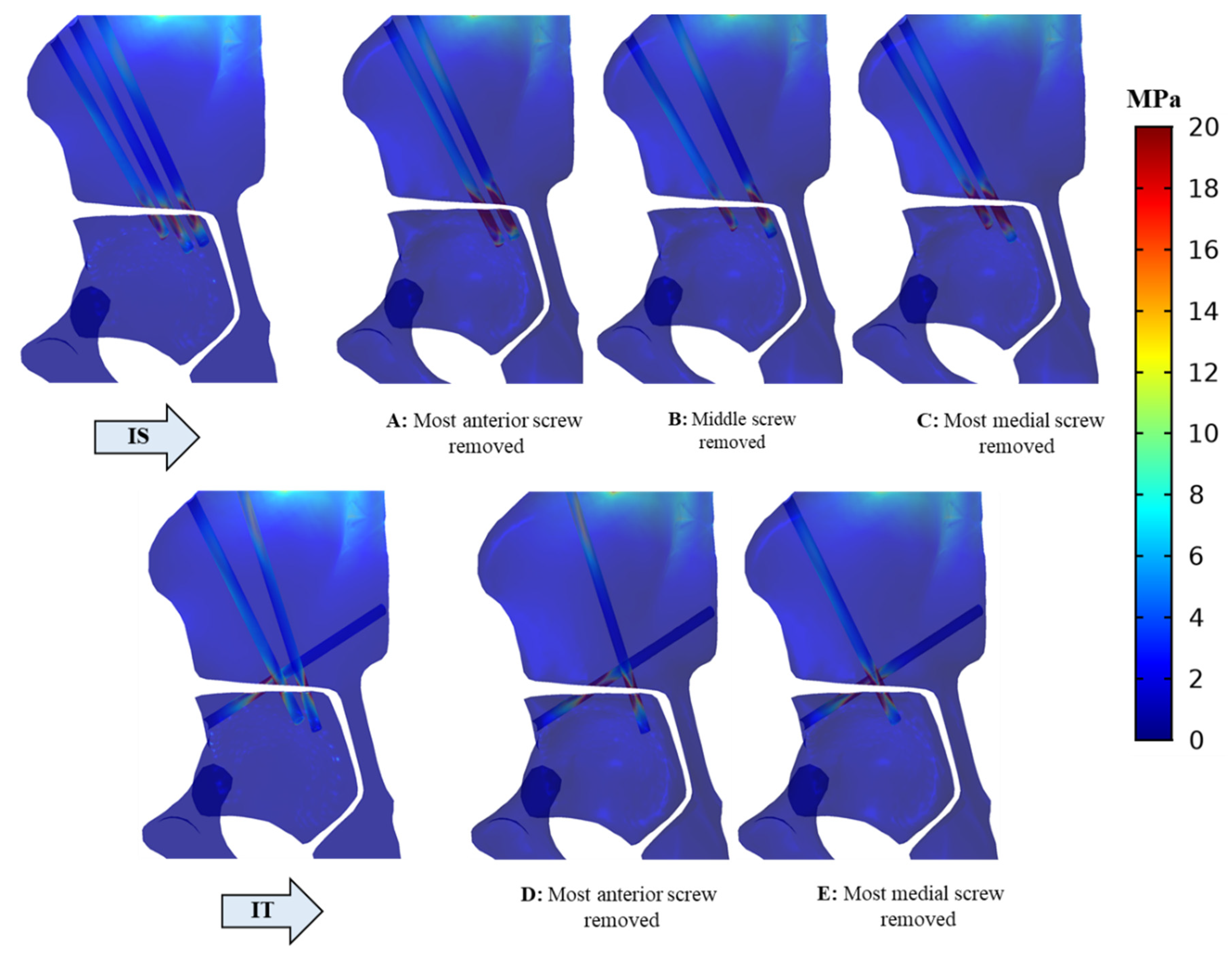
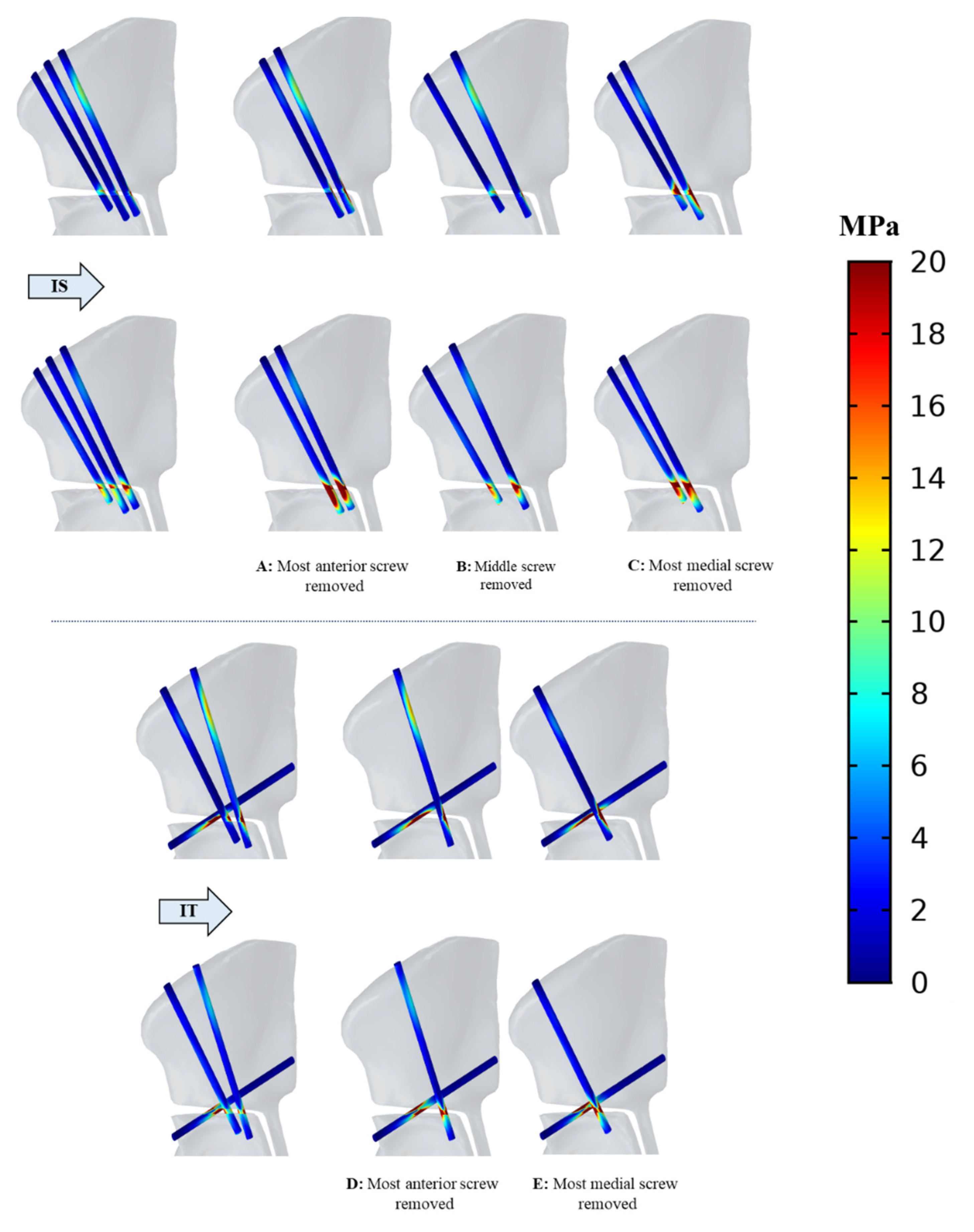
FE model of each screw configuration is generated using linear 10-node tetrahedral elements in COMSOL Multiphysics® (COMSOL AB, Stockholm, Sweden) (Figure 1). Mesh convergence analysis are performed for all the screw configurations to validate the accuracy and confidence of the simulations in which the initial mesh is chosen based on the physics of the simulation, and then the mesh is improved using adaptive mesh refinement provided in COMSOL. The error estimate is chosen so that the L2 norm of the gradient of the displacement squared is minimized everywhere in the model. The adaptive mesh refinement uses the Dual Weighted Residual (DWR) method that is based on a posteriori error estimation [24,25]. The mesh convergence analysis for IS construct of the first model is summarized in Table 1, where the maximum von Mises stress is calculated for each mesh iteration. The adaptive mesh refinement is separately performed with 1, 2 and 4 refinements succeeding the initial mesh with 217,390 number of elements. The results of convergence analysis demonstrate that all the refinement steps lead to identical peak stress with a similar number of elements, that is the improved FE mesh. Consequently, the mesh with one step refinement (i.e., 100,462 number of elements for IS) is chosen for each screw construct. Final number of elements for the remaining models are displayed in Table 2.
We discretize the cortical and trabecular regions of the pelvic bone using Hounsfield Unit (HU) intensity values extracted from the CT data. The cortical bone and high-strength alloy steel elements are assumed homogeneous, linearly elastic and isotropic with average Young’s modulus of 17 and 200 GPa, respectively [26]. For trabecular region, inhomogeneous material properties are assigned to each element of the pelvis based on the bone density observed from CT scan using a density phantom. For this purpose, first intensity values for each element are converted to calcium equivalent density using a linear relation [27]
ρ c a = 0.0008 × I N T 0.8037 ,
where ρ c a denote the calcium equivalent density of trabecular bone in ( gr / cm 2 ) and I N T is the intensity values. Next, calcium densities are converted to apparent densities using
ρ a p p = ρ c a / 0.626 ,
where ρ a p p is the apparent densities in ( gr / cm 2 ) The last step is to convert the apparent density to isotropic elastic modulus using an empirical relation [28]
E = 2017.3   ρ a p p 2.46 ,
where E is the elastic modulus in MPa. The Poisson’s ratio of 0.3 and 0.33 are assumed for the pelvic bone and screw elements, respectively [6,29].
The contact pressure distribution on the joint surface is estimated using nonlinear discrete element analysis (DEA) on the patient-specific model of the joint surface. DEA is an efficient computational method that can be used to determine the stress distribution in an articular cartilage and compute the joint contact pressure. DEA considers the cartilage layer as an elastic surface attached to the supporting bone and models the joint contact pressure profile with linear [3,12] or nonlinear [8,30] rigid bodies; compressive springs distributed over cartilage region. DEA computes the contact pressure in which the pelvis is fixed in all 6 degrees of freedom (DOF) while the femur is free to translate or rotate in any direction for establishing the equilibrium with the system of the springs. In this study, a loading condition simulating the peak force during normal walking is applied in the FE model. Considering the weight of each subject, the peak forces of 1167 (145.1, −130.1, 1151) N and 1991 (247.5, −221.9, 1963) N are calculated during walking for first and second models, respectively, as described by Bergmann et al. [31]. A fixed boundary condition in all 6 DOF is applied to the top surfaces of the pelvis located at the sacro-iliac joint of the pelvis to simulate the sacral support [6] (Figure 2).
The literature reveals that strain-based criterion is the most appropriate bone failure criterion for estimating fracture rick and predicting yield load [32]. We use maximum principal strain criterion to determine the volume of the failed elements where the bone tissue reaches the yield strain. For this purpose, we first compute the principal strains at the centroid of each bone element and determine the greater value of maximum tensile strain, | ε m a x | and minimum compressive strain, | ε m i n | The maximum strain value chosen is then compared with the appropriate compressive and tensile yield strains that is ε y C = 0.0104 for compression and ε y T = 0.0073 for tension [32,33]. A bone element is considered to be failed if its maximum strain exceeds the corresponding yield strain and eventually the volume of all the failed elements is computed. We then increase the gait load gradually in 0.01 N increments and repeat the FE simulation to recompute the total volume of the failed elements until it reaches 1% of the total volume of the pelvic bone. The load at that point is considered as the yield load of the pelvis subject to gait loading [33,34]. Bone stiffness is also calculated as the ratio of the applied gait load to the average displacement of the loaded nodes [33].

3. Results

Based on previous studies, von Mises stress is a good representation of stress distribution for evaluating different osteotomy methods and fixation techniques due to its impeccable prediction of injury or failure of bone tissues [6,27,35,36]. As shown in Figure 3, high stresses emerge at the osteotomized regions surrounding the screw holes in both pelvic and acetabular fragments, with peak values of 58.0 MPa and 70.11 MPa (Table 3) at the osteotomized pelvic fragments in the vicinity of the hole surface of the most medial fixation screw (third screw starting from the ASIS) in IS and transverse screw in IT configurations, respectively. We also compare the biomechanical performance of IS and IT fixation techniques for a second patient model, which has shown similar von Mises distribution subject to gait loading. Likewise, in the second model, the maximum von Mises stress of 28.5 MPa appears at the pelvic fragment surrounding the most medial fixation screw in IS which is lower than 76.4 MPa in proximity to the transverse screw in IT fixation. However, maximum compressive strain of IS configurations are 3.7% and 5.2% (Table 3) in the first and second, models, respectively, which are higher compared to those of the IT construct (2.5% and 4.8%). In addition, high von Mises stresses appear, at the interface as illustrated in Figure 3.
Similar distribution of normal and shear stresses is observed in the fixation screws (Figure 4) of the two models with the peak values appearing on the most medial fixation screw in the IS and the transverse screw in IT configuration surrounding the osteotomized site. The peak normal and shear stresses of the IT screws are, respectively, 74.8 and 49.8 MPa in first and second models (Table 3), which are higher than those of the IS method (56.0 and 37.8 MPa). Investigation of the displacement profile of both models demonstrate no significant difference between IS and IT configurations. Maximum displacement of the acetabular fragment in both configurations is reported as 1.0 mm and 3.7 mm for first and second models, respectively.
Using bone failure criterion based on “Maximum principal strain”, it is demonstrated that none of the screw configuration fails in the presence of gait load. FE simulations predict the yielding to start at the iliac crest considering the distribution of the failed elements on the onset of yielding (Figure 5). Furthermore, results predict slightly larger yield load for IT configurations compared to those of the IS (9% for the first model, 4% for the second model), whereas no substantial difference in bone stiffness for the given load are found between IS and IT fixation methods of each model (Table 3).
Investigation of simulation models with two fixation screws confirm that screw configuration A (Figure 6) with the most anterior IS fixation screw (first screw starting from the ASIS) removed, has 114 MPa peak von Mises stress and maximum compressive strain of 6.2% that are higher among all the other, 2-screw combinations and they are identified at the pelvic fragment in the vicinity of the most medial fixation screw. Similarly, higher normal and shear stresses (226 and 119 MPa) are found on the most medial fixation screw of configuration A (Figure 7) and consequently, predicted bone stiffness and yield load are substantially reduced in configuration A (1509 N/mm and 5380 N) (Table 4). Furthermore, screw configuration E with the most medial IT fixation screw removed, has larger values of stresses and strain in pelvic bone (Figure 6), interface and fixation screws (Figure 7) and therefore lower values of bone stiffness and yield load (1609 N/mm and 6828 N) has been predicted as compared to the configuration D with the most anterior IT fixation screw removed. (Table 4).

4. Discussion

Periacetabular osteotomy is a well-established surgical treatment for developmental dysplasia of the hip. To obtain the optimal method for stabilizing the acetabular fragment, various fixation techniques have been introduced, and their biomechanical strength have been compared through in vitro experiments [16,17,20]. Use of FEA has been proven to be effective in orthopedics applications [7,26,27,33,35,36,37]; however, the biomechanical comparison of different fixation techniques of PAO with the use of FEA is missing in the literature. In this paper, we assess the biomechanical performance of two popular fixation techniques: iliac and transverse screw configurations, with the aid of FE analysis. We also aim to distinguish the biomechanical efficacy and significance of each IS and IT fixation screw located at the iliac crest in stabilizing the acetabular fragment after PAO by creating additional FE models with different combinations of two fixation screws. Multiple factors correlate with the degree of the complexities involved in screw placement after PAO, including but not limited to the patient demography (e.g., weight, gender and age), geometry and size of the bony anatomy, and thickness of the ilium and acetabulum. It is important to note that placing the transverse fixation screw along with two other screws inserted from the iliac crest in a way that screws do not impinge on each other or breach the walls of the ilium and acetabulum is more challenging.
Biomechanical simulation of two patient models predicts on average 7% larger yield load for IT construct with no significance difference in bone stiffness and displacement between two configurations. Similar results were reported by Yassir et al. [20]. The yield load is computed by increasing the simulated gait load until 1% of the volume of the bone elements within the model fail based on the yield strains. Inevitably, IS configuration reaches the failure limit point at iliac crest relatively sooner whereas more failed elements appear in the acetabular fragment of the IT model on the onset of yielding (Figure 5). Moreover, maximum compressive strain of the pelvic bone in IT is on average 17% lower compared to IS configuration; however, peak von Mises stress in osteotomized pelvic and acetabular fragments are estimated to be on average 40% and 32% lower in IS, respectively. Furthermore, simulation results demonstrate that IS fixation screws are exposed to lower normal and shear stresses in peak value (on average 31%). Simulation results; therefore, support the fact that transverse technique has not indicated promising superiority and advantage in biomechanical performance over the iliac to justify the additional challenge and time that may associate with the placement of the fixation screws in IT construct.
Simulation results also demonstrate that peak von Mises stress in pelvic and acetabular fragment are, respectively, 10–58% and 48–247% higher in screw configuration A with the most anterior fixation screw removed; furthermore, the maximum compressive strain of the bone is 55–170% larger in Model A as compared to the remaining 2-screw models. Two fixation screws in this model are also under higher peak values of normal and shear stresses (on average 55–94%). Moreover, FE predicts that bone stiffness and yield load are 2–9% and 16–37% lower in configuration A, respectively. Comparing with the original 3-screw IS construct, von Mises stress and compressive strain of both fragments in configuration A have been increased by average 82% and 68%, respectively, and maximum normal and shear stresses of the fixation screws have been elevated by on average 260%. In addition, there have been 10% and 42% drops in bone stiffness and yield load of configuration A, respectively, compared to the traditional IS. Biomechanical analysis, therefore, confirms that the most anterior screw in the IS construct contribute significantly to creating, adequate compression thereby providing optimum inherent joint stability and biomechanical strength for both acetabular and osteotomized pelvic fragments.
The biomechanical comparison between 2-screw combinations D and E of the IT group indicates that peak von Mises stress and compressive strain in both fragments are on average 12% and 13% larger, respectively, in configuration E with the most medial fixation screw removed with higher peak values of normal and shear stresses emerging in fixation screws (on average 12%). Furthermore, bone stiffness and yield load are, respectively, 3% and 14% lower in the configuration E as compared to the configuration D with the most anterior fixation screw removed. Comparing the biomechanics of configuration E with standard 3-screw IT construct, we observe that peak von Mises stress in the acetabular fragment and peak normal and shear stresses within the fixation screws have been raised by, respectively, 48%, 92% and 56%. Moreover, stiffness and yield load in pelvic bone have been shown to be decreased by 5% and 32%, respectively. Simulation results suggest that the most medial fixation screw inserting from the iliac crest in IT construct has a strong impact on providing sufficient stability and strength in the acetabular fragment after PAO.
Among all 2-screw combinations, configuration B in IS group (Table 4) with no middle fixation screw, has shown relatively comparable biomechanical performance to that of 3-screws IS. To elaborate, simulation results illustrate lower peak values of stresses in pelvic bone (14–46%) and fixation screws (29–60%) compared to the remaining 2-screw configurations. In addition, bone yield load is predicted to be 7–58% larger in the configuration B, that is 92% of the estimated yield load in the IS. As a result, one could argue that the fixation screw located in between of the other two in IS configuration has the least influence in stabilizing the acetabular fragment.
Consistent with the current clinical diagnosis and biomechanical analysis of the hip dysplasia, we only consider the biomechanical strength and stability of screw fixation techniques in the presence of the gait loads [9,16,17,38,39,40,41,42,43]. The effects of different loading conditions reflecting other activities are not considered in this study. Similar to [6], we also apply simplifications in the definition of the FE models, such as geometrical modeling of the screws as a cylindrical solid with no threads to obtain feasible and coherent results. However, the fact that the objective of this study is to acquire biomechanical comparison between different fixation techniques in identical conditions justifies the FE simplifications. The focus of this study is to compare the outcomes of two different screw configurations. Due to the limitations and difficulties that surgeons encounter throughout screw placement (e.g., limited and confined space in acetabular and osteotomized pelvic fragments), finding the optimal configuration of the fixation screws is not considered in this study. Therefore, considering individual-based model variations is out of the scope of the current study. To rule out the effects of bone geometry, density and patient demography on the simulation results, we run the simulation on a second model and verify that these variations do not affect the findings. In both models, biomechanical parameters suggest no significant superiority of the IT configuration over the IS.
Future simulations must consider the effects of variation in direction, thickness and depth of the fixation screws. In the future, cadaveric experiments also need to be performed to further justify the comparison results. Moreover, the biomechanical comparison between screw fixation techniques would benefit from long-term follow-up clinical outcome studies to investigate the healing process after PAO with each of the screw placements.

5. Conclusions

In this paper, we provide a detailed FE model to investigate the biomechanical behavior of the iliac and transverse fixation techniques in periacetabular osteotomy that would assist the surgeons in assessing the advantages of each method. No significant biomechanical difference is found between two screw configurations in both patient models. Simulation results of 2-screw configurations demonstrate superior biomechanical performance of configuration B in IS group with two most anterior and medial screws, which is relatively comparable to those of 3-screws IS.

Author Contributions

Conceptualization, M.B., A.F., J.E.T., P.D.S. and M.A.; methodology, M.B., A.F., R.J.M., R.B.G. and M.A.; software, M.B.; validation, M.B. and M.A.; formal analysis, M.B.; investigation, M.B.; resources, M.A.; data curation, M.B. and M.A.; writing—original draft preparation, M.B.; writing—review and editing, M.B., A.F., R.J.M., R.B.G., J.E.T., P.D.S. and M.A.; visualization, M.B.; supervision, M.A.; project administration, M.A.; funding acquisition, M.A. All authors have read and agreed to the published version of the manuscript.

Funding

This research was funded by the National Institute of Biomedical Imaging and Bioengineering (NIBIB) of the National Institutes of Health (NIH), grant numbers R01 EB023939 and R21 EB020113. The content is solely the responsibility of the authors and does not necessarily represent the official views of the National Institutes of Health.

Institutional Review Board Statement

The study was conducted according to the guidelines of the Declaration of Helsinki, and approved by the Institutional Review Board of Johns Hopkins Medicine JHM (protocol code IRB NA_00001257 and JHM IRB1 #05-09-02-01 and date of approval 21 April 2015).

Informed Consent Statement

Informed consent was obtained from all subjects involved in the study.

Data Availability Statement

The data presented in this study are available on request from the corresponding author.

Acknowledgments

This research was also supported through internal funds from department of Orthopedic Surgery in Johns Hopkins Medical School.

Conflicts of Interest

The authors declare no conflict of interest.

References

  1. Cooperman, D.R.; Wallensten, R.; Stulberg, S.D. Acetabular dysplasia in the adult. Clin. Orthopaed. Related Res. 1983, 175, 79–85. [Google Scholar] [CrossRef]
  2. Ganz, R.; Klaue, K.; Vinh, T.S.; Mast, J.W. A new periacetabular osteotomy for the treatment of hip dysplasias technique and preliminary results. Clin. Orthopaed. Related Res. 1988, 232, 26–36. [Google Scholar] [CrossRef]
  3. Armand, M.; Lepistö, J.; Tallroth, K.; Elias, J.; Chao, E. Outcome of periacetabular osteotomy: Joint contact pressure calculation using standing AP radiographs, 12 patients followed for average 2 years. Acta Orthopaed. 2005, 76, 303–313. [Google Scholar] [CrossRef] [Green Version]
  4. Lepistö, J.; Armand, M.; Armiger, R.S. Periacetabular osteotomy in adult hip dysplasia–developing a computer aided real-time biomechanical guiding system (BGS). Suomen Ortoped. Traumatol. Ortoped. Traumatol. Finland Finn. J. Orthopaed. Traumatol. 2008, 31, 186. [Google Scholar]
  5. Armiger, R.S.; Armand, M.; Tallroth, K.; Lepistö, J.; Mears, S.C. Three-dimensional mechanical evaluation of joint contact pressure in 12 periacetabular osteotomy patients with 10-year follow-up. Acta Orthopaed. 2009, 80, 155–161. [Google Scholar] [CrossRef] [PubMed] [Green Version]
  6. Lin, C.; Ltcl, L.H.; Wwdm, H.P. Stress Distribution of a Modified Periacetabular Osteotomy for Treatment of Dysplastic Acetabulum. J. Med. Biol. Eng. 2010, 31, 53–58. [Google Scholar]
  7. Zou, Z.; Chávez-Arreola, A.; Mandal, P.; Board, T.N.; Alonso-Rasgado, T. Optimization of the position of the acetabulum in a ganz periacetabular osteotomy by finite element analysis. J. Orthopaed. Res. 2013, 31, 472–479. [Google Scholar] [CrossRef]
  8. Niknafs, N.; Murphy, R.J.; Armiger, R.S.; Lepisto, J.; Armand, M. Biomechanical factors in planning of periacetabular osteotomy. Front. Bioeng. Biotechnol. 2013, 1, 20. [Google Scholar] [CrossRef] [PubMed] [Green Version]
  9. Gaffney, B.M.; Clohisy, J.C.; Van Dillen, L.R.; Harris, M.D. The association between periacetabular osteotomy reorientation and hip joint reaction forces in two subgroups of acetabular dysplasia. J. Biomech. 2020, 98, 109464. [Google Scholar] [CrossRef] [PubMed]
  10. Park, S.-J.; Lee, S.-J.; Chen, W.-M.; Park, J.-H.; Cho, Y.-S.; Shin, T.; Kwon, S.-Y. Computer-Assisted Optimization of the Acetabular Rotation in Periacetabular Osteotomy Using Patient’s Anatomy-Specific Finite Element Analysis. Appl. Bion. Biomech. 2018, 2018, 9730525. [Google Scholar] [CrossRef] [Green Version]
  11. De Raedt, S.; Mechlenburg, I.; Stilling, M.; Rømer, L.; Murphy, R.J.; Armand, M.; Lepistö, J.; de Bruijne, M.; Søballe, K. Reliability of computer-assisted periacetabular osteotomy using a minimally invasive approach. Int. J. Comput. Assist. Radiol. Surg. 2018, 13, 2021–2028. [Google Scholar] [CrossRef] [PubMed]
  12. An, K.; Himeno, S.; Tsumura, H.; Kawai, T.; Chao, E. Pressure distribution on articular surfaces: Application to joint stability evaluation. J. Biomech. 1990, 23, 1013–1020. [Google Scholar] [CrossRef]
  13. Li, G.; Sakamoto, M.; Chao, E.Y. A comparison of different methods in predicting static pressure distribution in articulating joints. J. Biomech. 1997, 30, 635–638. [Google Scholar] [CrossRef]
  14. Matheney, T.; Kim, Y.-J.; Zurakowski, D.; Matero, C.; Millis, M. Intermediate to long-term results following the Bernese periacetabular osteotomy and predictors of clinical outcome. J. Bone Jt. Surg. 2009, 91, 2113–2123. [Google Scholar] [CrossRef]
  15. Hussell, J.G.; Rodriguez, J.A.; Ganz, R. Technical complications of the Bernese periacetabular osteotomy. Clin. Orthopaed. Related Res. 1999, 363, 81–92. [Google Scholar] [CrossRef]
  16. Babis, G.C.; Trousdale, R.T.; Jenkyn, T.R.; Kaufman, K. Comparison of two methods of screw fixation in periacetabular osteotomy. Clin. Orthopaed. Related Res. 2002, 403, 221–227. [Google Scholar] [CrossRef]
  17. Widmer, B.J.; Peters, C.L.; Bachus, K.N.; Stevens, P.M. Initial stability of the acetabular fragment after periacetabular osteotomy: A biomechanical study. J. Pediat. Orthopaed. 2010, 30, 443–448. [Google Scholar] [CrossRef] [PubMed]
  18. Crockarell, J.; Trousdale, R.T.; Cabanela, M.E.; Berry, D.J. Early experience and results with the periacetabular osteotomy. The Mayo Clinic experience. Clin. Orthopaed. Related Res. 1999, 363, 45–53. [Google Scholar] [CrossRef]
  19. Matta, J.M.; Stover, M.D.; Siebenrock, K. Periacetabular osteotomy through the Smith-Petersen approach. Clin. Orthopaed. Related Res. 1999, 363, 21–32. [Google Scholar]
  20. Yassir, W.; Mahar, A.; Aminian, A.; Newton, P.; Wenger, D. A comparison of the fixation stability of multiple screw constructs for two types of pelvic osteotomies. J. Pediatric Orthopaed. 2005, 25, 14–17. [Google Scholar]
  21. Murphy, R.J.; Armiger, R.S.; Lepistö, J.; Mears, S.C.; Taylor, R.H.; Armand, M. Development of a biomechanical guidance system for periacetabular osteotomy. Int. J. Comput. Assist. Radiol. Surg. 2015, 10, 497–508. [Google Scholar] [CrossRef] [Green Version]
  22. Murphy, R.J.; Armiger, R.S.; Lepistö, J.; Armand, M. Clinical evaluation of a biomechanical guidance system for periacetabular osteotomy. J. Orthopaed. Surg. Res. 2016, 11, 1–8. [Google Scholar] [CrossRef] [Green Version]
  23. Pieper, S.; Halle, M.; Kikinis, R. 3D Slicer. In Proceedings of the 2004 2nd IEEE International Symposium on Biomedical Imaging: Nano to Macro, Arlington, VA, USA, 18–18 April 2004; pp. 632–635. [Google Scholar]
  24. Becker, R.; Rannacher, R. An optimal control approach to a posteriori error estimation in finite element methods. Acta Numer. 2001, 10, 1–102. [Google Scholar] [CrossRef]
  25. Eriksson, K.; Estep, D.; Hansbo, P.; Johnson, C. Introduction to adaptive methods for differential equations. Acta Numer. 1995, 4, 105–158. [Google Scholar] [CrossRef]
  26. Dalstra, M.; Huiskes, H.; van Erning, L. Development and validation of a three-dimensional finite element model of the pelvic bone. J. Biomech. Eng. Trans. ASME 1995, 117, 272–278. [Google Scholar] [CrossRef] [Green Version]
  27. Anderson, A.E.; Peters, C.L.; Tuttle, B.D.; Weiss, J.A. Subject-specific finite element model of the pelvis: Development, validation and sensitivity studies. J. Biomech. Eng. 2005, 127, 364–373. [Google Scholar] [CrossRef] [Green Version]
  28. Dalstra, M.; Huiskes, R.; Odgaard, A.v.; Van Erning, L. Mechanical and textural properties of pelvic trabecular bone. J. Biomech. 1993, 26, 523–535. [Google Scholar] [CrossRef] [Green Version]
  29. Tanino, H.; Ito, H.; Higa, M.; Omizu, N.; Nishimura, I.; Matsuda, K.; Mitamura, Y.; Matsuno, T. Three-dimensional computer-aided design based design sensitivity analysis and shape optimization of the stem using adaptive p-method. J. Biomech. 2006, 39, 1948–1953. [Google Scholar] [CrossRef]
  30. Volokh, K.; Chao, E.; Armand, M. On foundations of discrete element analysis of contact in diarthrodial joints. Mol. Cell. Biomech. MCB 2007, 4, 67. [Google Scholar]
  31. Bergmann, G.; Deuretzbacher, G.; Heller, M.; Graichen, F.; Rohlmann, A.; Strauss, J.; Duda, G. Hip contact forces and gait patterns from routine activities. J. Biomech. 2001, 34, 859–871. [Google Scholar] [CrossRef]
  32. Yosibash, Z.; Tal, D.; Trabelsi, N. Predicting the yield of the proximal femur using high-order finite-element analysis with inhomogeneous orthotropic material properties. Philos. Trans. R. Soc. A Math. Phys. Eng. Sci. 2010, 368, 2707–2723. [Google Scholar] [CrossRef]
  33. Basafa, E.; Armiger, R.S.; Kutzer, M.D.; Belkoff, S.M.; Mears, S.C.; Armand, M. Patient-specific finite element modeling for femoral bone augmentation. Med. Eng. Phys. 2013, 35, 860–865. [Google Scholar] [CrossRef] [Green Version]
  34. Pistoia, W.; Van Rietbergen, B.; Lochmüller, E.-M.; Lill, C.; Eckstein, F.; Rüegsegger, P. Estimation of distal radius failure load with micro-finite element analysis models based on three-dimensional peripheral quantitative computed tomography images. Bone 2002, 30, 842–848. [Google Scholar] [CrossRef]
  35. Rhyu, K.; Kim, Y.; Park, W.; Kim, K.; Cho, T.-J.; Choi, I. Application of finite element analysis in pre-operative planning for deformity correction of abnormal hip joints–a case series. Proc. Instit. Mech. Eng. Part H J. Eng. Med. 2011, 225, 929–936. [Google Scholar] [CrossRef]
  36. Phillips, A.; Pankaj, P.; Howie, C.; Usmani, A.; Simpson, A. Finite element modelling of the pelvis: Inclusion of muscular and ligamentous boundary conditions. Med. Eng. Phys. 2007, 29, 739–748. [Google Scholar] [CrossRef] [PubMed]
  37. Hsu, J.-T.; Tsai, M.-T.; Chang, C.-H.; Fuh, L.-J.; Lai, K.-A.; Liu, Z.-L.; Tu, M.-G.; Huang, H.-L. Finite element analysis of the effects of sizes of acetabular components on the initial stability of the acetabular cup. J. Med. Biol. Eng. 2008, 28, 59–63. [Google Scholar]
  38. Sucato, D.J.; Tulchin, K.; Shrader, M.W.; DeLaRocha, A.; Gist, T.; Sheu, G. Gait, Hip Strength and Functional Outcomes After a Ganz Periacetabular Osteotomy for Adolescent Hip Dysplasia. J. Pediatric Orthopaed. 2010, 30, 344–350. [Google Scholar] [CrossRef] [PubMed]
  39. Mechlenburg, I.; Nyengaard, J.; Rømer, L.; Søballe, K. Changes in load-bearing area after Ganz periacetabular osteotomy evaluated by multislice CT scanning and stereology. Acta Orthopaed. Scand. 2004, 75, 147–153. [Google Scholar] [CrossRef] [PubMed]
  40. Gahramanov, A.; İnanıcı, F.; Çağlar, Ö.; Aksoy, C.; Tokgözoğlu, A.M.; Güner, S.; Baki, A.; Atilla, B. Functional Results in Periacetabular Osteotomy: Is it Possible to Obtain a Normal Gait after the Surgery? HIP Int. 2017, 27, 449–454. [Google Scholar] [CrossRef] [PubMed]
  41. Nishimura, M.; Takahira, N.; Fukushima, K.; Yamamoto, T.; Moriya, M.; Uchiyama, K. Early gait analysis after curved periacetabular osteotomy for acetabular dysplasia. Orthoped. Res. Rev. 2015, 7, 25–32. [Google Scholar] [CrossRef] [Green Version]
  42. Schroeder, C.; Zavala, L.; Opstedal, L.; Becker, J. Recovery of Lower Extremity Function in the Initial Year Following Periacetabular Osteotomy: A Single Subject Analysis. Physiother. Theory Pract. 2020, 1–12. [Google Scholar] [CrossRef] [PubMed]
  43. Swarup, I.; Zaltz, I.; Robustelli, S.; Sink, E. Outcomes of periacetabular osteotomy for borderline hip dysplasia in adolescent patients. J. Hip Preservat. Surg. 2020, 7, 249–255. [Google Scholar] [CrossRef] [PubMed]
Figure 1. Geometrical and FE models of different screw configurations in PAO.
Biomechanics 01 00010 g001
Figure 2. Fixed Boundary and loading conditions.
Biomechanics 01 00010 g002
Figure 3. Von Mises stress distribution after PAO in pelvic bone (top), acetabular Fragment (middle) and osteotomized pelvic fragment (bottom) fixated with IS and IT screw configurations.
Biomechanics 01 00010 g003
Figure 4. Distribution of the normal stress (top) and shear stress (bottom) at the fixation screws for IS and IT configuration.
Biomechanics 01 00010 g004
Figure 5. Location of the failed bone elements (black) on the onset of yielding for patient 1.
Biomechanics 01 00010 g005
Figure 6. Von Mises stress distribution after PAO in pelvic bone for different combinations of IS and IT configurations.
Biomechanics 01 00010 g006
Figure 7. Distribution of the normal stress (top) and shear stress (bottom) at the fixation screws for different combinations of IS and IT configurations.
Biomechanics 01 00010 g007
Table 1. Mesh convergence analysis for IS configuration of patient 1.
Mesh Iteration Initial MeshOne Step RefinementTwo Step RefinementFour Step Refinement
Number of elements217,390100,462100,419100,380
Maximum von Mises Stress (MPa)104.59140.48140.33140.26
Table 2. Number of elements in FE model meshes.
ModelNumber of Elements
Patient 1
IS100,380
IT102,424
IS first screw removed76,999
IS middle screw removed74,900
IS third screw removed73,455
IT first screw removed76,401
IT second screw removed73,448
Patient 2
IS203,057
IT226,367
Table 3. Biomechanics of IS and IT screw configurations.
Patient 1Patient 2
ISITISIT
Peak von Mises stress in osteotomized pelvic fragment (MPa)58.070.128.576.4
Peak von Mises stress in acetabular fragment (MPa)24.129.926.548.3
Peak compressive strain in both fragments (%)3.72.55.24.8
Peak normal stress in fixation screws (MPa)56.074.867.3103
Peak shear stress in fixation screws (MPa)37.849.845.773.6
Peak normal stress in interface (MPa)31.352.535.259.8
Peak shear stress in interface (MPa)30.136.327.740.2
Bone stiffness (N/mm)16771703755760
Bone yield load (N)923210,10714,53415,111
Table 4. Biomechanics in different 2-screw configurations of patient 1.
ISIT
A: Most
Anterior Screw
Removed
B: Middle Screw
Removed
C: Most
Medial Screw Removed
D: Most
Anterior Screw Removed
E: Most
Medial Screw Removed
Peak von Mises stress in osteotomized pelvic fragment (MPa)11458.371.5100104
Peak von Mises stress in acetabular fragment (MPa)40.325.5 27.211.613.8
Peak compressive strain in both fragments (%)6.23.44.02.32.6
Peak normal stress in fixation screws (MPa)22680.0140121 144
Peak shear stress in fixation screws (MPa)11959.266.174.477.9
Peak normal stress in interface (MPa)18955.383.987.892.8
Peak shear stress in interface (MPa)68.536.338.053.053.2
Bone stiffness (N/mm)15091665154116571609
Bone yield load (N)53808485641979246828
Publisher’s Note: MDPI stays neutral with regard to jurisdictional claims in published maps and institutional affiliations.

