Computational Analysis of Self-Expanding and Balloon-Expandable Transcatheter Heart Valves


1
Department of Engineering, University of Palermo, 90128 Palermo, Italy
2
Department for the Treatment and Study of Cardiothoracic Diseases and Cardiothoracic Transplantation, IRCCS-ISMETT, 90128 Palermo, Italy
*
Author to whom correspondence should be addressed.
Biomechanics 2021, 1(1), 43-52; https://0-doi-org.brum.beds.ac.uk/10.3390/biomechanics1010004
Submission received: 31 December 2020
/
Revised: 3 March 2021
/
Accepted: 9 March 2021
/
Published: 11 March 2021
Abstract
:Bicuspid aortic valve (BAV) patients are usually excluded from transcatheter aortic valve implantation (TAVI) as this valve anatomy likely leads to oval expansion. This study presents a numerical study of TAVI using both self-expanding and balloon expandable transcatheter heart valve (THV) in bicuspid patients with severe stenosis. The simulation framework included a patient-specific anatomy of the aortic root, calcifications and BAV leaflets extracted from medical imaging analysis as well as a realistic crimping and deployment of the THV. Tissue stress analysis highlighted local maxima in the contact area between the inner aortic lumen and the THV stent frame. Flow analysis based on the smoothed particle hydrodynamics (SPH) technique displayed the area at risk of paravalvular leakage (PVL). These findings provide insights on the TAVI in BAV and thus represents a further step towards the use of in-silico for the virtual planning of TAVI, aiming at improving not only the efficacy of the implantation but also the exploration of borderline anatomy as the case of TAVI in BAVs.
1. Introduction
Bicuspid aortic valve (BAV) is the one of the major contraindication for transcatheter aortic valve implantation (TAVI) as this non-invasive procedure likely determines paravalvular leak (PVL) and oval expansion of the device. Moreover, the occurrence of stenosis in BAV patients usually occurs at a younger age than that of individuals with the morphological-normal tricuspid aortic valve. The BAV is predisposed to the development of stenosis due to increased mechanical stress and have a predisposition to calcium formation [1]. Thus, BAV anatomy remains a significant cause of mortality and morbidity in elderly patients having conventionally high surgical risk [2].
In the setting of high-risk patients, TAVI has emerged as the main strategy as opposed to conventional surgical repair of the tricuspid aortic valve. There is a need to expand TAVI into lower-risk patient groups and this was feasible thanks to the design advances of the new generation of THVs. Indeed, successful TAVI procedures in stenotic BAVs have been recently reported [3,4] and suggested that a relative proportion of BAV patients is expected to be treated in the next years. The balloon-expandable Edwards SAPIEN 3 was successfully implanted in bicuspid patients with severe stenosis [5]. Recently, Brouwer et al. have demonstrated the potential utilize of the self-expanding Medtronic Evolut PRO device in bicuspid patients [6]. As TAVI expands into lower-risk patients, computational simulations integrating patient-specific anatomy and realistic device modeling represents a valid tool to support the pre-operative planning of TAVI and may allow virtual evaluation of the feasibility of the device implantation in complex anatomy as BAV.
We sought to determine the structural mechanics and hemodynamics of Medtronic Evolut PRO self-expanding THV and the Edwards SAPIEN 3 balloon-expandable THV when implanted in bicuspid patients. The computational framework relays on a patient-specific anatomic reconstruction of two patients who underwent TAVI in our hospital institution. We performed a finite-element analysis to simulate the THV expansion followed by fluid-solid interaction analysis based on smoothed particle hemodynamic (SPH) method to assess the region at risk of PVL. Simulation results are here discussed.
2. Materials and Methods
2.1. Clinical Procedure
The study was performed on n.2 patients with severe stenosis of BAV that were treated by TAVI in our hospital institution. At computed-tomography (CT) imaging, an experienced radiologist assessed the bicuspid phenotypic pattern of valve leaflet fusion. One patient presented a right-left cusp fusion of the BAV leaflet and was treated with the 29 mm SAPIEN 3 THV. Specifically, the native annulus diameter measured by multiplanning CT imaging modality was 28.4 mm, thereby suggesting the implantation of the 29 mm SAPIEN 3 device. The second patient had a pure bicuspid valve phenotype with annulus size of 23.5 mm that was treated with the 26 mm Evolut Pro device according to manufacturer recommendations and clinician experience. TAVI procedure was performed according to manufacturer indication and physician experience [7]. The study was approved by our local ethics review committees, and patients gave informed consent to their inclusion in the study.
2.2. Computational Strategy
The computational simulation strategy of TAVI consisted of (a) the anatomic reconstruction of aortic root model, (b) the simulation of preoperative scenario, (c) the crimping and deployment of THVs by finite-element analysis (FEA), d) the fluid-solid interaction analysis by SPH technique for estimating the PVL.
2.2.1. Anatomic Reconstruction and Meshing
Pre-procedural CT images at diastolic phase were processed by Mimics (Materialise, Belgium) to segment the aortic root anatomy and calcific plaques using different greyvalues and multiple masks as done previously [8,9,10]. In a different way, the native valve leaflets were mapped onto the reconstructed aortic model using a parametric morphologic model of BAV leaflet surfaces [9]. Once the segmented anatomy was extrapolated, the aortic root and calcifications were exported as stereolithographic (STL) files for the element discretization. The meshing procedure was done using the ICEM meshing software (Ansys v.18, ANSYS, Inc., Cannonsburg, PA, USA). Both the aortic root luminal surface and native BAV leaflet surfaces were discretized with structured quadrilateral shell elements with reduced integration. Calcific plaques were meshed by a combination of hexahedral and tetrahedral solid elements (element size of 0.1 mm). The aortic root wall and BAV leaflet surfaces had uniform thickness of 2.2 mm and 0.5 mm, respectively.
2.2.2. THV Models
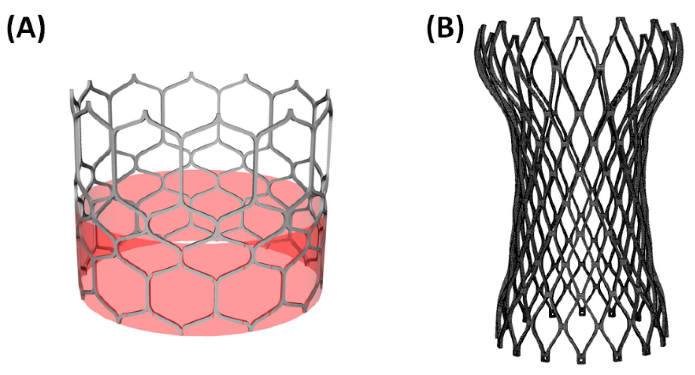
A high-resolution micro-CT scanner was used to acquire the stent frame of both the self-expanding and balloon-expandable and then a general reverse engineering approach was adopted to generate the computer-aided-design (CAD) model of each device (Figure 1A). The SAPIEN 3 (Edwards Lifesciences, CA, USA) is manufactured by a cobalt-chromium alloy frame with four cells for each row and twelve columns. The bovine pericardial leaflets are anchored by sutures. In a different way, the Evolut Pro (Medtronic, MI, USA) consisted of a supra-annular, self-expanding nitinol frame with a porcine pericardial tissue valve (Figure 1B). Nearly, 60,000 structured-hexahedral solid elements with reduced integration were used to discretize the SAPIEN 3 frame while 128,000 structured elements were adopted for the Evolut Pro THV.
For the balloon-expandable THV, Von Mises plasticity and isotropic hardening was used for modeling the SAPIEN 3 stent frame (E = 233 × 103 MPa, ν = 0.3, σy = 414 MPa, σULT = 930 MPa, εp = 0.45) [11,12]. For the self-expanding Evolut PRO, the mechanical properties of pseudo-elastic metallic frame (i.e., n.14 material descriptors) were taken from literature and then implemented in the pre-processing software solver using the built-in material subroutine in Abaqus (Abaqus 2018, Dassault Systemes, FR) [11,13].
For each THV, the sealing skirt was modeled using structured-quadrilateral shell elements with size of 0.3 mm and elasto-plastic stress-strain model (E = 55 MPa, ν = 0.49, σy = 6.6 MPa, σULT = 6.6 MPa, εp = 0.6). Prosthetic valve leaflets were modeled using a general 3D parametric geometry of the native aortic valve leaflet as done by Bailey et al. [14].
2.2.3. FEA of TAVI in BAV Patients
Numerical analysis of TAVI procedure were done in Abaqus/Explicit using a quasi-static process by monitoring energy and ensuring the ratio of kinetic energy to internal energy remains less than 10%. The stable time increment is dependent on both the smallest element size and the deployment wave speed. To improve computational efficiency, the actual duration of deployment is reduced by increasing the rate at which the load is applied in the analysis. This may increase inertial forces so that the final time step of 0.1 s was obtained after a time-dependency study. Time step was applied while an element-by-element stable time increment estimate, coupled with a “variable mass scaling technique” that was kept between 10−7 and 10−8. Contacts among components were defined according to the general contact algorithm available in Abaqus/Explicit. Tie contact condition was instead used to couple the calcification to the aortic valve leaflets.
The pre-TAVI scenario was obtained applying a uniform pressure loading on the native bicuspid leaflet surface in Abaqus/Explicit (simulation time 0.05 s). This pressure loading is equal to the difference in the pressure between the left ventricle and the aorta. In this way, we had enough space for the THV positioning without penetration with others components. The aortic root wall and native BAV leaflets were modeled as hyperelastic and isotropic materials using a two-term Yeoh constitutive relation. Specifically, the material parameters of the aortic root were C1 = 0.015 MPa and C2 = 0.158 MPa while the native BAV leaflets had C1 = 0.008 MPa and C2 = 0.048 MPa [15,16]. A linear elastic model was used to model the stiff calcific plaque (E = 10 MPa and ν = 0.49).
2.2.4. Crimping and Deployment
Prior to THV deployment, each device was crimped using a cylindrical surface gradually moved along the radial direction from the initial device diameter to the final diameter of 6 mm. Frictionless contact was defined between crimping surface and THV. For each patient, the THV was positioned according to the implantation depth and tilt angle suggested by the Heart Team for performing TAVI in each patient.
Expansion of SAPIEN 3 stent frame was modeled by the radial displacement of a rigid cylindrical surface representing the wall of the expanding balloon as suggested by other studies [12,13]. This is a valid assumption since angiography shows negligible axis rotation and translation during stent expansion. The cylindrical surface is enlarged from the initial diameter of 6 mm to the nominal diameter of SAPIEN 3 frame. For the expansion, the stress field resulting from the crimping was imported to account for the initial residual stress of the crimped SAPIEN 3 THV.
For the Evolut Pro device, the crimped model was imported in the patient anatomic model with its residual stresses from the previous crimping simulation, together with the geometry of the sleeve (the crimped crimper). Both the stent and sleeve were positioned in the aortic root, where the lower end of the stent was located 6 mm from the annulus, as recommended by the manufacturer. By pulling the sleeve towards the aorta and releasing the stent, as a result of its residual stresses, the stent was gradually expanded inside the calcified leaflets. The pull out of the rigid sleeve was performed by a uniform displacement of 30 mm.
In all cases, frictionless contact was enabled between the THV surface and other components (i.e., aortic root, native BAV leaflet and calcific plaque). After expansion with either the SAPIEN 3 or Evolut Pro, an elastic recoil of 0.05 s was allowed by the release of the cylindrical surface or the rigid sleeve. Then, prosthetic valve leaflets were mapped onto the implanted stent frames at initial stress-free closed configuration as described by Auricchio et al. [11]. As boundary conditions, the proximal and distal ends of the aortic root wall were fixed in longitudinal and circumferential directions of the vessel using cylindrical coordinate system.
2.2.5. SPH-Based Fluid-Solid Interaction Analysis
The SPH numerical technique is ideal for simulating the dynamic behavior of the fluid-solid interaction occurring during valve closure/opening. This approach is a meshless numerical method defining a body by a collection of points, instead of using nodes and elements. Starting from the simulation of THV deployment, the deformed configuration was exported in the computer-aided-design (CAD) software Rhinoceros to obtain the fluid domain. The proximal and distal ends of the aortic root were extended to ensure a fully developed flow. Then, two rigid surfaces were generated perpendicular to the extensions of the aortic root and were then imported in Abaqus/Explicit as rigid surfaces. These rigid surfaces plates were moved along the perpendicular direction of each extension to apply the boundary conditions on the fluid volume. Specifically, motion of the rigid plates was obtained by applying a time-varying pressure according to transmural pressure seen by the aortic valve. At the inlet flow, the rigid plate was loaded with the blood pressure exerted by the left ventricle while the outlet rigid plate was loaded with the pressure occurring in the aortic valve surface seen by the aorta. Blood was assumed as Newtonian fluid with density of 1060 kg/m3 and viscosity of 0.0035 Pa s using the pressure-density relation governed by the linear Hugoniot equation of state (artificial sound speed of c0 = 145 m/s). Particles were distributed in the fluid domain with a spatial resolution of 0.5 mm as suggested by the mesh sensitivity done by Mao et al. [17]., Figure 2 shows the physiological pressure waveforms that were used to obtain the pressure gradient between the left ventricle and aorta.. Contacts were enabled between particles and other components to allow fluid-solid interaction. The starting point of the SPH simulation was the systole. For each THV, two cardiac cycles each of 0.8 s were carried out, and the particle velocity field from the second cycle was analyzed.
3. Results
3.1. Self-Expanding Medtronic Pro
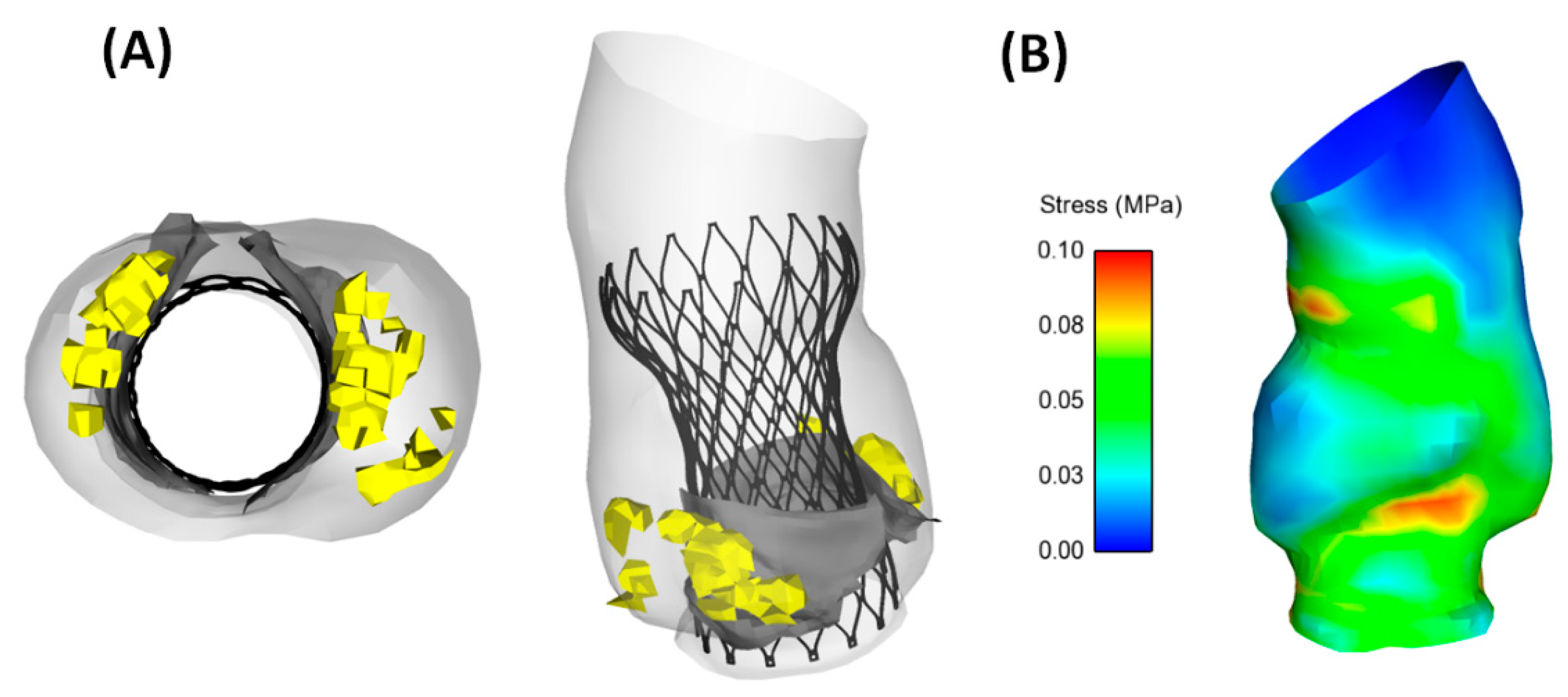
Analysis of aortic wall stress induced by the self-expanding nitinol frame determined local maxima in correspondence of the left ventricular outflow tract and the proximal ascending aorta (Figure 3B). We observed a circular shape of the deployed Evolut Pro in the complex bicuspid anatomy of the patient with a pure BAV. Specifically, the size of the Evolut pro at cross section in correspondence of the sinus of Valsalva was characterized by a diameter of 28 mm (Figure 3A).
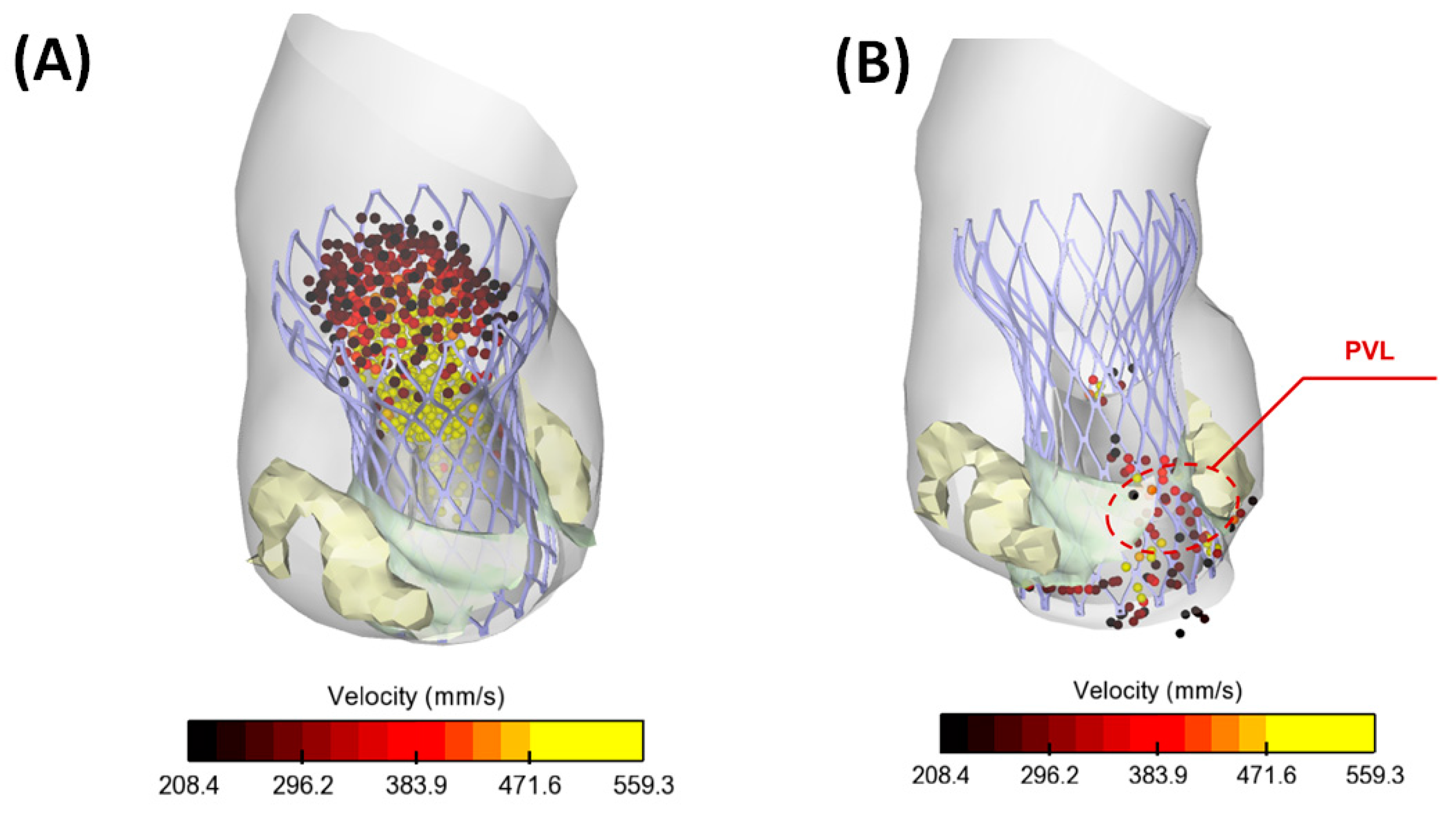
Flow jet from the prosthetic heart valve exhibited a uniform distribution during systolic peak while a small amount retrograde flow was observed during late diastole (Figure 4). This suggests flow circulating in the gap between the aortic wall and the Evolut Pro near the commissure of the BAV, thereby suggesting the occurrence of PVL.
3.2. Ballon-Expandable SAPIEN 3 THV
Aortic wall stress wall was characterized by local maxima in the contact area of the aorta with either SAPIEN 3 or calcifications (Figure 5B). SAPIEN 3 expanded asymmetrically with the lateral side of device being longer than the opposite side and elliptical shape at annulus (Figure 5A). Specifically, elliptical measurement was characterized by a major axis of 27.7 mm and minor axis of 24.4 mm). A cross-section of aortic model near annulus evinced the presence of a small gap (area of 4.1 mm2) between the metallic frame and aortic root wall, although this area did not lead to remarkable amount of PVL.
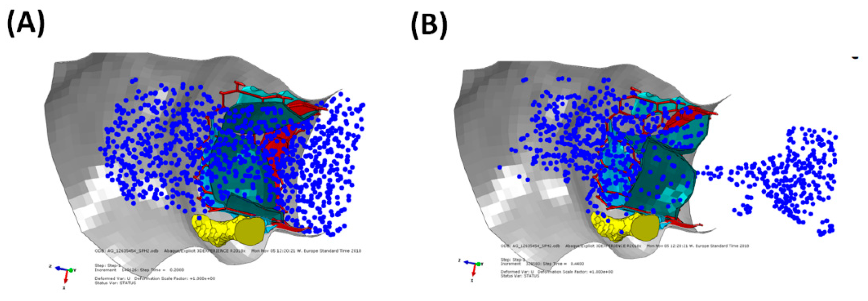
Figure 6 shows the circulating particle in the gap area between the aortic wall and the deployed SAPIEN 3 device. We found a marginal presence of PVL and well-functioning prosthetic vale leaflets with aortic valve area of 1.24 cm2, mean gradient of 16 mmHg and flow jet of 2.4 m/s.
4. Discussion
This study documented the feasibility of TAVI in a bicuspid patient and demonstrated the potentiality of computer simulations to support interventional cardiologists in the virtual planning of THV when implanted in borderline patient case as bicuspid patients. Qualitative variables were extrapolated from numerical simulation. Specifically, the structural mechanics was assessed by the contact pressure between the device and the aortic wall and the implanted device shape at aortic annulus. Flow dynamic was achieved by the SPH technique to visualize the flow during cardiac beating. We performed TAVI simulation on two patients receiving the balloon-expandable SAPIEN 3 and the self-expanding Evolut Pro THVs. Although the study did not include a validation with clinical data and the investigation on non-bicuspid TAVI cases, the computational approach here proposed could be a useful tool to predict several clinically relevant information of TAVI in BAV.
TAVI in bicuspid patients is challenging because of morphological features (not observed in the tricuspid aortic valve) that make the outcomes of the intervention less predictable. However, several recent investigations highlighted the feasibility of TAVI in the setting of BAV [5,18,19]. Using the S3 valve, Arai et al. [5] found a comparable degree of PVL between bicuspid and tricuspid patients. In a large series, Hayashida and collaborators [19] highlighted no significant differences in the device performance, risk of annulus rupture and valve migration of BAV versus tricuspid patients. It is believed that the feasibility and safety of TAVI in BAV is likely a consequence of the design advancements incorporated by the new-generation THV devices that partially overcome some of the limitations encountered in treating the complex bicuspid anatomy. As here reported, the simulation of TAVI confirmed clinical evidence of an elliptical expansion of THV due to the oval bicuspid shape and a small gap between the aortic wall and THV.
Simulations demonstrated the presence of stress concentrations induced by the contact between the stent frame and the aortic wall [13] as a major risk indicator of aortic rupture. Other research groups evinced the impact of aortic root anatomy [12], calcification patterns [20] and native leaflets [14] on the outcome of TAVI. However, these studies focused on patients with the tricuspid aortic valve to simulate the implantation of both Edwards SAPIEN XT and Medtronic Corevalve THVs. Few investigations are focused on TAVI in BAV. Brouwer et al. [6] performed a computational flow analysis to assess PVL in bicuspid patients treated with the newer generation of bioprosthesis (i.e., the Medtronic CoreValve Evolut R). Moreover, Lavon et al. [21] corroborated clinical evidences of asymmetric and elliptical deployment of the stent frame with both the Evolut PRO and CoreValve devices using an ideal aortic model with BAV. A similar study showed optimal conformability to the elliptical BAV with both the Lotus and ACURATE THVs [22]. Recently, a combined structural and hemodynamic analysis was performed with the Living Heart Human model [23], which is capable of simulating the cardiac beating of whole heart. The broad numerical methodology represented a valid and predictive tool not only to determine the performance of THVs but also for improving valve design optimization to minimize the reported complications. In a previous study [8], we simulated the SAPIEN 3 deployment in a cohort of n.8 patients with stenotic BAV and found that the tendency of the S3 device to expand asymmetrically in the aortic root. In this study, a comparison between the SAPIEN 3 and Evolut Pro shows differences in the anatomical conformability of the investigated device. The SAPIEN 3 is characterized by high radial strength at implanted host because of the higher material strength. When deployed, the SAPIEN 3 undergoes local plastic deformation keeping the device enlarged and in contact with the aortic wall. This has led to a more elliptical shape of the device in the bicuspid anatomy as compared with the self-expanding THV. In a different way, the Evolut pro is characterized by more conformability because of superelastic behavior of the nitinol material. Thus, the stiff calcific plaque has likely limited the opening of the Evolut Pro, which portends to a more circular shape as compared to the SAPIEN 3 device. However, patients here investigated presented different annulus sizes and were treated with different THV sizes. Thus, a direct comparison of simulation results is not straightforward so that the study needs to be extended to patients matched for the aortic annulus size. Further analysis on a large population is needed to confirm these findings.
This study has several limitations including the constitutive modeling of the aortic wall, the expansion guided by radial displacement rather than balloon inflation and the friction between THVs and aortic root. A comparison with imaging data (i.e., CT and ultrasound) is necessary to validate these findings. The SPH method has several limitations including spatial resolution and the lack of shear stress determination. A high mesh particle number is necessary to observe sufficient particles circulating in the small gaps between the aortic root and THV frame, but this can increase the computational cost. Although mesh sensitivity was chosen according to the SPH-related study on THV [17], our study is missing a detailed verification based on in-vitro testing or clinical imaging. However, this study demonstrated the predictive capability of computational simulations to support physicians on the clinical-decision making of TAVI using quantitative parameters (i.e., contact pressure and flow analysis), besides the clinical information based only on the preoperative CT examination. The computational framework here proposed may also assist the design of next-generation of THVs by means of in-silico clinical trials, thereby reducing the time-to-market application.
5. Conclusions
We conclude that this study represents a further step towards the use of personalized simulations for virtual planning of TAVI, aiming at improving not only the efficacy of the implantation but also the exploration of borderline application as the TAVI for stenotic bicuspid patient. Further study is necessary to validate the computational approach with post-TAVI CT imaging and echocardiographic data on a large patient cohort.
Author Contributions
Conceptualization, S.P. and C.G.; methodology, S.P. and C.G.; software, S.P.; validation, S.P. and C.G.; formal analysis, S.P.; investigation, S.P.; resources, C.G.; data curation, S.P. and C.G.; writing—original draft preparation, S.P. and C.G.; writing—review and editing, S.P. and C.G.; visualization, S.P.; supervision, C.G. All authors have read and agreed to the published version of the manuscript.
Funding
This research received no external funding.
Institutional Review Board Statement
The study was conducted according to the guidelines of the Declaration of Helsinki, and approved by the Institutional Review Board of ISMETT (protocol code IRRB/04/04 and date of approval 14.04.20).
Informed Consent Statement
Informed consent was obtained from all subjects involved in the study.
Data Availability Statement
Not applicable.
Conflicts of Interest
The authors declare no conflict of interest.
References
- Kong, W.K.; Delgado, V.; Poh, K.K.; Regeer, M.V.; Ng, A.C.; McCormack, L.; Yeo, T.C.; Shanks, M.; Parent, S.; Enache, R.; et al. Prognostic Implications of Raphe in Bicuspid Aortic Valve Anatomy. JAMA Cardiol. 2017, 2, 285–292. [Google Scholar] [CrossRef]
- Roberts, W.C.; Janning, K.G.; Ko, J.M.; Filardo, G.; Matter, G.J. Frequency of congenitally bicuspid aortic valves in patients >/=80 years of age undergoing aortic valve replacement for aortic stenosis (with or without aortic regurgitation) and implications for transcatheter aortic valve implantation. Am. J. Cardiol. 2012, 109, 1632–1636. [Google Scholar] [CrossRef]
- Kawamori, H.; Yoon, S.H.; Chakravarty, T.; Maeno, Y.; Kashif, M.; Israr, S.; Abramowitz, Y.; Mangat, G.; Miyasaka, M.; Rami, T.; et al. Computed tomography characteristics of the aortic valve and the geometry of SAPIEN 3 transcatheter heart valve in patients with bicuspid aortic valve disease. Eur. Heart J. Cardiovasc. Imaging 2018, 19, 1408–1418. [Google Scholar] [CrossRef]
- Perlman, G.Y.; Blanke, P.; Dvir, D.; Pache, G.; Modine, T.; Barbanti, M.; Holy, E.W.; Treede, H.; Ruile, P.; Neumann, F.J.; et al. Bicuspid Aortic Valve Stenosis: Favorable Early Outcomes With a Next-Generation Transcatheter Heart Valve in a Multicenter Study. JACC Cardiovasc. Interv. 2016, 9, 817–824. [Google Scholar] [CrossRef] [PubMed]
- Arai, T.; Lefevre, T.; Hovasse, T.; Morice, M.C.; Romano, M.; Benamer, H.; Garot, P.; Hayashida, K.; Bouvier, E.; Chevalier, B. The feasibility of transcatheter aortic valve implantation using the Edwards SAPIEN 3 for patients with severe bicuspid aortic stenosis. J. Cardiol. 2017, 70, 220–224. [Google Scholar] [CrossRef] [Green Version]
- Brouwer, J.; Gheorghe, L.; Nijenhuis, V.J.; Ten Berg, J.M.; Rensing, B.; van der Heyden, J.A.S.; Swaans, M.J. Insight on patient specific computer modeling of transcatheter aortic valve implantation in patients with bicuspid aortic valve disease. Catheter. Cardiovasc. Interv. 2018. [Google Scholar] [CrossRef]
- Gandolfo, C.; Turrisi, M.; Follis, F.; Clemenza, F.; Falletta, C.; Gentile, G.; Liotta, R.; Raffa, G.M.; Pilato, M. Acute Obstructive Thrombosis of Sapien 3 Valve After Valve-in-Valve Transcatheter Aortic Valve Replacement for Degenerated Mosaic 21 Valve. JACC Cardiovasc. Interv. 2018, 11, 215–217. [Google Scholar] [CrossRef] [PubMed]
- Pasta, S.; Cannata, S.; Gentile, G.; Di Giuseppe, M.; Cosentino, F.; Pasta, F.; Agnese, V.; Bellavia, D.; Raffa, G.M.; Pilato, M.; et al. Simulation study of transcatheter heart valve implantation in patients with stenotic bicuspid aortic valve. Med. Biol. Eng. Comput. 2020. [Google Scholar] [CrossRef]
- Pasta, S.; Gentile, G.; Raffa, G.M.; Scardulla, F.; Bellavia, D.; Luca, A.; Pilato, M.; Scardulla, C. Three-dimensional parametric modeling of bicuspid aortopathy and comparison with computational flow predictions. Artif. Organs 2017, 41, E92–E102. [Google Scholar] [CrossRef]
- Rinaudo, A.; Raffa, G.M.; Scardulla, F.; Pilato, M.; Scardulla, C.; Pasta, S. Biomechanical implications of excessive endograft protrusion into the aortic arch after thoracic endovascular repair. Comput. Biol. Med. 2015, 66, 235–241. [Google Scholar] [CrossRef]
- Auricchio, F.; Conti, M.; Morganti, S.; Reali, A. Simulation of transcatheter aortic valve implantation: A patient-specific finite element approach. Comput. Methods Biomech. Biomed. Eng. 2014, 17, 1347–1357. [Google Scholar] [CrossRef]
- Finotello, A.; Morganti, S.; Auricchio, F. Finite element analysis of TAVI: Impact of native aortic root computational modeling strategies on simulation outcomes. Med. Eng. Phys. 2017, 47, 2–12. [Google Scholar] [CrossRef]
- Morganti, S.; Conti, M.; Aiello, M.; Valentini, A.; Mazzola, A.; Reali, A.; Auricchio, F. Simulation of transcatheter aortic valve implantation through patient-specific finite element analysis: Two clinical cases. J. Biomech. 2014, 47, 2547–2555. [Google Scholar] [CrossRef] [PubMed]
- Bailey, J.; Curzen, N.; Bressloff, N.W. Assessing the impact of including leaflets in the simulation of TAVI deployment into a patient-specific aortic root. Comput. Methods Biomech. Biomed. Eng. 2016, 19, 733–744. [Google Scholar] [CrossRef] [PubMed] [Green Version]
- Morganti, S.; Brambilla, N.; Petronio, A.S.; Reali, A.; Bedogni, F.; Auricchio, F. Prediction of patient-specific post-operative outcomes of TAVI procedure: The impact of the positioning strategy on valve performance. J. Biomech. 2016, 49, 2513–2519. [Google Scholar] [CrossRef]
- Pasta, S.; Rinaudo, A.; Luca, A.; Pilato, M.; Scardulla, C.; Gleason, T.G.; Vorp, D.A. Difference in hemodynamic and wall stress of ascending thoracic aortic aneurysms with bicuspid and tricuspid aortic valve. J. Biomech. 2013, 46, 1729–1738. [Google Scholar] [CrossRef] [PubMed] [Green Version]
- Mao, W.; Li, K.; Sun, W. Fluid-Structure Interaction Study of Transcatheter Aortic Valve Dynamics Using Smoothed Particle Hydrodynamics. Cardiovasc Eng. Technol. 2016, 7, 374–388. [Google Scholar] [CrossRef] [Green Version]
- Yoon, S.H.; Bleiziffer, S.; De Backer, O.; Delgado, V.; Arai, T.; Ziegelmueller, J.; Barbanti, M.; Sharma, R.; Perlman, G.Y.; Khalique, O.K.; et al. Outcomes in Transcatheter Aortic Valve Replacement for Bicuspid Versus Tricuspid Aortic Valve Stenosis. J. Am. Coll. Cardiol. 2017, 69, 2579–2589. [Google Scholar] [CrossRef] [PubMed] [Green Version]
- Hayashida, K.; Bouvier, E.; Lefevre, T.; Chevalier, B.; Hovasse, T.; Romano, M.; Garot, P.; Watanabe, Y.; Farge, A.; Donzeau-Gouge, P.; et al. Transcatheter Aortic Valve Implantation for Patients With Severe Bicuspid Aortic Valve Stenosis. Circ. Cardiovasc. Interv. 2013, 6, 284–291. [Google Scholar] [CrossRef] [PubMed] [Green Version]
- Sturla, F.; Ronzoni, M.; Vitali, M.; Dimasi, A.; Vismara, R.; Preston-Maher, G.; Burriesci, G.; Votta, E.; Redaelli, A. Impact of different aortic valve calcification patterns on the outcome of transcatheter aortic valve implantation: A finite element study. J. Biomech. 2016, 49, 2520–2530. [Google Scholar] [CrossRef] [PubMed] [Green Version]
- Lavon, K.; Marom, G.; Bianchi, M.; Halevi, R.; Hamdan, A.; Morany, A.; Raanani, E.; Bluestein, D.; Haj-Ali, R. Biomechanical modeling of transcatheter aortic valve replacement in a stenotic bicuspid aortic valve: Deployments and paravalvular leakage. Med. Biol. Eng. Comput. 2019, 57, 2129–2143. [Google Scholar] [CrossRef] [PubMed]
- Gorla, R.; Casenghi, M.; Finotello, A.; De Marco, F.; Morganti, S.; Regazzoli, D.; Bianchi, G.; Acerbi, E.; Popolo Rubbio, A.; Brambilla, N.; et al. Outcome of transcatheter aortic valve replacement in bicuspid aortic valve stenosis with new-generation devices. Interact. Cardiovasc. Thorac. Surg. 2020. [Google Scholar] [CrossRef] [PubMed]
- Ghosh, R.P.; Marom, G.; Bianchi, M.; D’Souza, K.; Zietak, W.; Bluestein, D. Numerical evaluation of transcatheter aortic valve performance during heart beating and its post-deployment fluid-structure interaction analysis. Biomech. Modeling Mechanobiol. 2020, 19, 1725–1740. [Google Scholar] [CrossRef] [PubMed]
Figure 1.
CAD models of (A) balloon-expandable SAPIEN 3 THV and (B) self-expanding Evolut Pro; models are not at same scale.
Figure 1.
CAD models of (A) balloon-expandable SAPIEN 3 THV and (B) self-expanding Evolut Pro; models are not at same scale.

Figure 2.
Simulation model for the SPH analysis showing the boundary condition applied to inlet and outlet plate to move particle.
Figure 2.
Simulation model for the SPH analysis showing the boundary condition applied to inlet and outlet plate to move particle.

Figure 3.
(A) Deformed configuration of the implanted self-expanding Evolut Pro and (B) map of intramural stress (i.e., maximum principal stress).
Figure 3.
(A) Deformed configuration of the implanted self-expanding Evolut Pro and (B) map of intramural stress (i.e., maximum principal stress).

Figure 4.
(A) SPH flow from the Evolut PRO THV at peak systole and (B) at early diastole showing PVL.
Figure 4.
(A) SPH flow from the Evolut PRO THV at peak systole and (B) at early diastole showing PVL.

Figure 5.
(A) Deformed configuration of the implanted balloon-expandable SAPIEN 3 and (B) map of intramural stress (i.e., maximum principal stress).
Figure 5.
(A) Deformed configuration of the implanted balloon-expandable SAPIEN 3 and (B) map of intramural stress (i.e., maximum principal stress).

Figure 6.
(A) SPH flow from the SAPIEN 3 THV at peak systole and (B) at early diastole showing PVL.

Publisher’s Note: MDPI stays neutral with regard to jurisdictional claims in published maps and institutional affiliations. |
© 2021 by the authors. Licensee MDPI, Basel, Switzerland. This article is an open access article distributed under the terms and conditions of the Creative Commons Attribution (CC BY) license (http://creativecommons.org/licenses/by/4.0/).
Share and Cite
MDPI and ACS Style
Pasta, S.; Gandolfo, C. Computational Analysis of Self-Expanding and Balloon-Expandable Transcatheter Heart Valves. Biomechanics 2021, 1, 43-52. https://0-doi-org.brum.beds.ac.uk/10.3390/biomechanics1010004
AMA Style
Pasta S, Gandolfo C. Computational Analysis of Self-Expanding and Balloon-Expandable Transcatheter Heart Valves. Biomechanics. 2021; 1(1):43-52. https://0-doi-org.brum.beds.ac.uk/10.3390/biomechanics1010004
Chicago/Turabian StylePasta, Salvatore, and Caterina Gandolfo. 2021. "Computational Analysis of Self-Expanding and Balloon-Expandable Transcatheter Heart Valves" Biomechanics 1, no. 1: 43-52. https://0-doi-org.brum.beds.ac.uk/10.3390/biomechanics1010004