All articles published by MDPI are made immediately available worldwide under an open access license. No special
permission is required to reuse all or part of the article published by MDPI, including figures and tables. For
articles published under an open access Creative Common CC BY license, any part of the article may be reused without
permission provided that the original article is clearly cited. For more information, please refer to
https://0-www-mdpi-com.brum.beds.ac.uk/openaccess.
Feature papers represent the most advanced research with significant potential for high impact in the field. A Feature
Paper should be a substantial original Article that involves several techniques or approaches, provides an outlook for
future research directions and describes possible research applications.
Feature papers are submitted upon individual invitation or recommendation by the scientific editors and must receive
positive feedback from the reviewers.
Editor’s Choice articles are based on recommendations by the scientific editors of MDPI journals from around the world.
Editors select a small number of articles recently published in the journal that they believe will be particularly
interesting to readers, or important in the respective research area. The aim is to provide a snapshot of some of the
most exciting work published in the various research areas of the journal.
The paper proposes the analytic modelling of flexible textile shields made of fabrics with inserted conductive yarns and metallic plasma coating in order to calculate their electromagnetic shielding effectiveness (EMSE). This manufacturing process is highly innovative, since copper plasma coating improves EMSE on the fabrics with inserted conductive yarns of stainless steel and silver with 10–15 dB in the frequency range of 0.1–1000 MHz, as shown by the measured EMSE values determined according to the standard ASTM ES-07 via the Transverse Electromagnetic (TEM) cell. On the other hand, modelling of EMSE for such conductive flexible shields gives an insight on estimating EMSE in the design phase of manufacturing the shield, based on its geometric and electrical parameters. An analytic model was proposed based on the sum of EMSE of the fabric with inserted conductive yarns and EMSE of the copper coating. The measurement results show close values to the proposed analytic model, especially in case of fabric with conductive yarns having stainless steel content.
The shielding of electromagnetic non-ionizing radiation by means of flexible textile materials is a well-established field of research in the current context. The use of various electronic devices, mobile phones and other gadgets has yielded significant pollution from electromagnetic (EM) radiation in our environment [1]. Shielding is needed in many applications since non-ionizing radiation from various sources may cause interference (EMI) with other electronic devices or even cause harmful effects on human health [2,3]. Due to their advantages when compared to metallic shields, such as low weight, good mechanical strength, adaptability to various shapes of objects for shielding, as well as cost-effectiveness, textile materials with electric conductive properties offer a proper solution on these aspects [4].
Several papers tackle this innovative field of research and contributions in this regard may be grouped in various topics. The main topic of research is new manufacturing methods for EMI shielding textiles. Within the cited review paper [5], the following main manufacturing technologies for EMI shielding fabrics are presented: applying intrinsic conductive polymers, incorporating metallic nanoparticles in coatings [6], embedding conductive ingredients into the spinning solutions of fibers and interweaving metallic yarns (silver, copper, steel) with other conventional textile yarns [7,8]. A second topic is given by imparting additional functionalities to EMI shielding: electroless plating was used to deposit Co and Ni coating on Tencel fabrics for enhanced EMI shielding properties and corrosion resistance properties [9]. Another new manufacturing method integrates silver nanowire networks and polyurethane protective layers into the fabrics structure, with outstanding washing durability and chemical stability properties [10].
A third topic of research provides improved or adapted methods for the determination of electric properties of conductive textiles, including electromagnetic shielding effectiveness (EMSE) [11].
A final identified topic of research in this field is modelling of the EMSE for various conductive textile structures. Shielding of EM radiation is an important topic in the field of electromagnetic compatibility [12,13,14]. The main analytic relations for modelling the shielding effectiveness are based on the models originating from the circuit method [15] and the impedance method [16]. In order to fulfill specific conditions occurring in the practical situations where electromagnetic shielding is required, additional analytic relations have been developed and adapted for different geometric shapes of electromagnetic shields under various physical premises.
Estimation of the electrical properties in the case of fabrics is of great importance for the design of applications in relation to end-user requirements [16]. Since the process of manufacturing fabric samples involves a series of preparatory processes, modelling of electromagnetic shielding effectiveness (EMSE) means savings in terms of design duration, material resources and working time [17]. Two main technologies may be distinguished for imparting electrically conductive properties to textile materials. According to [18], the insertion of conductive yarns within the fabric structure (woven, knitted and nonwoven fabrics) and coating with conductive pastes of the plain fabrics.
Various analytic relations for estimating the shielding effectiveness (EMSE) have been adapted for both types of technologies. For woven fabrics with inserted conductive yarns, due to their mesh grid structure, the impedance method with correction factors was adapted [19]. Moreover, another analytic relation establishes a weighted sum between the EMSE of the layer and the EMSE of the grid [20]. These relations were applied for Transverse Electromagnetic (TEM) cell measured fabric samples by [21], taking into consideration reflection as the main component of EMSE.
Another shielding model was developed for mesh grid structures, based on the analogy with an RLC electric circuit with lumped elements [22]. Research work of estimating EMSE of mesh grid structures was accomplished by analogy with small aperture antennas [23]. A contribution to model EMSE for woven fabrics in shielding the near EM field based on the circuit method (introduced by H. Kaden [12,15]) was provided within [24]. Regarding the estimation of EMSE for coated fabrics, the main research direction goes for calculating the permittivity coefficient of the coating [18]. Various coating technologies and related analytic methods for estimation of EMSE were provided by [19].
In our research, both technologies for imparting conductive properties to fabrics were combined: fabrics with inserted conductive yarns were coated by magnetron plasma sputtering from a metallic target. Silver and stainless steel yarns were inserted in cotton woven fabrics and the as-obtained textiles were coated with copper thin films. The aim of our research is to model EMSE for this new type of conductive fabric with inserted conductive yarns in warp and weft direction and conductive plasma coating based on the sum of each conductive structure contributing to EMSE, namely the woven fabric with inserted conductive yarns and the copper coating on both sides of the fabric. The validation of these proposed analytic relations was conducted through electric sheet resistivity measurements and EMSE measurements via the TEM cell according to ASTM ES-07 standard.
2. Materials and Methods
The stainless steel yarns of type Bekinox BK 50/2 were purchased from Bekaert and the silver yarns of type Statex 117/17 dtex were purchased from Statex Produktions- und Vertriebs GmbH companies and used for fabric weaving. Cotton was used as a base material for the textiles. A copper target of 8 × 4 × 0.5 inches of purity 99.999% was purchased from K.J. Lesker and used in the magnetron sputtering system at The National Institute for Laser, Plasma and Radiation Physics (INFLPR).
2.1. Materials—Weaving
The woven fabrics based on cotton yarns with inserted conductive yarns were manufactured at SC Majutex SRL, Barnova Iasi. Stainless steel yarns (Bekinox BK 50/2) and silver yarns (Statex 117/17 dtex) were inserted both in warp and weft system on the weaving loom of type SOMET width 1.90 m. The woven fabrics were designed with plain weave for a simple and efficient structure of EM shields, while the basic support yarn was of 100% cotton Nm 50/2. Two types of woven fabrics with inserted conductive yarns of stainless steel (F1) and silver (F3) resulted, having a mesh grid distance of 5 mm.
2.2. Materials—Magnetron Plasma Coating
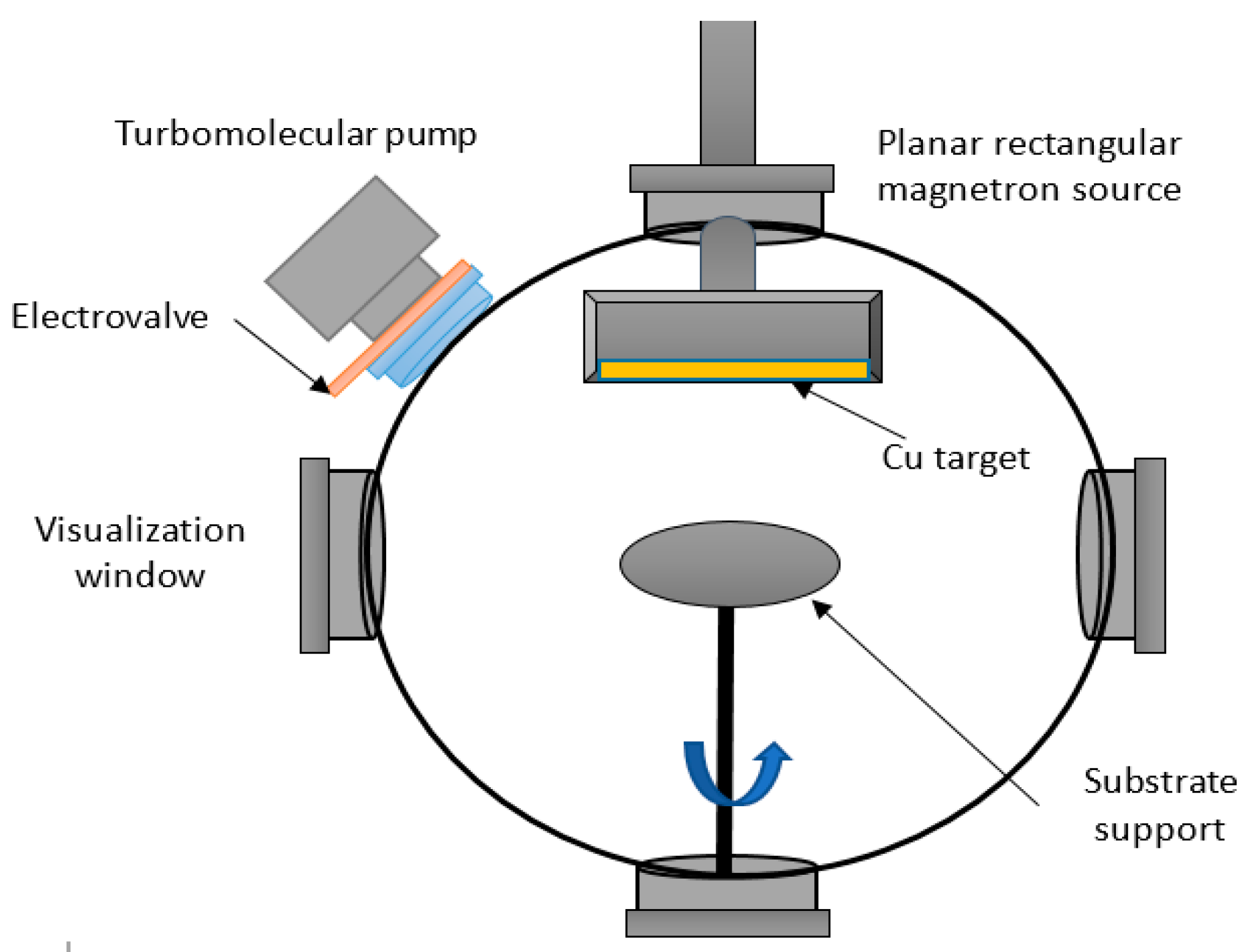
The copper coating onto the textile fabrics was performed at INFLPR into a dedicated stainless steel spherical vacuum chamber (K.J. Lesker, East Sussex, UK), pumped out by an assembly of a fore pump and turbomolecular pump (Pfeiffer, Memmingen, Germany), which allowed the obtaining of a base pressure down to 3 × 10⁻⁵ mbar. A constant argon flow (purity 6.0) of 50 sccm was continuously introduced into the chamber by means of a Bronkhorst mass flow controller, which allowed to establish the processing pressure around 5 × 10⁻³ mbar. The chamber is provisioned with a rectangular magnetron sputtering gun from K.J. Lesker, accommodating the high purity copper target. The discharge was ignited by means of a radio frequency generator (13.56 MHz) provisioned with an automatic matching box for adapting the impedance, and the deposition time was set to ensure coating thicknesses in the range 1200–10,000 nm on each side of the textile fabrics. Enhanced deposition uniformity was achieved by rotating the samples during the deposition process (200 rotations/min).
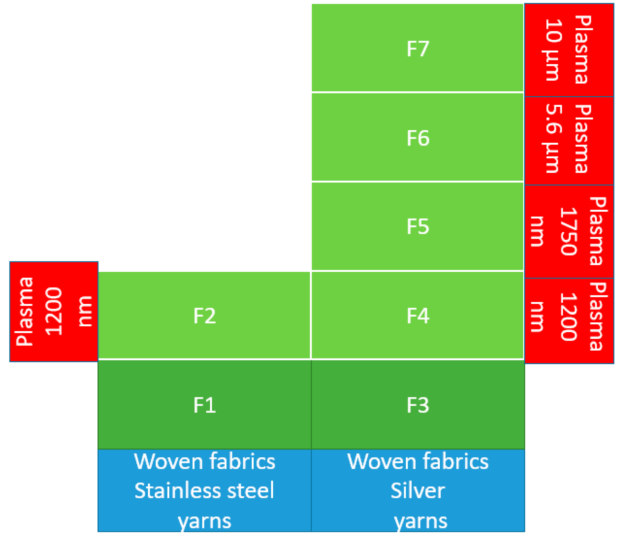
Figure 1 presents a sketch of the experimental set-up of the magnetron plasma equipment of INFLPR. Sample F2 resulted by plasma coating of F1 (stainless steel yarns) on both sides with 1200 nm of Copper, while samples F4, F5, F6 and F7 resulted by coating F3 (silver yarns) on both sides with 1200 nm, 1750 nm, 5600 nm and 10,000 nm of copper, respectively. More details regarding the experimental plan considered for the validation of the model is summarized in Figure 2.
2.3. Textile Samples
The structural and physical properties of textile samples subjected to modelling and validation of electromagnetic shielding effectiveness (EMSE) are presented in Table 1 for the yarns and Table 2 for the fabrics, emphasizing the data of particular significance for the modelling.
The corresponding scheme of the textile samples subjected to modelling and validation of electromagnetic shielding effectiveness (EMSE) is presented in Figure 2.
2.4. Morphology and Structure of the Textile Sample
The scheme of woven fabric with inserted metallic yarns and plasma coating is presented in Figure 3. The copper coating on the fabric with inserted metallic yarns does not create a continuous surface layer, but rather an additional electrically conductive grid on metallically the fabric yarns, increasing the fabric’s conductivity and its shielding properties.
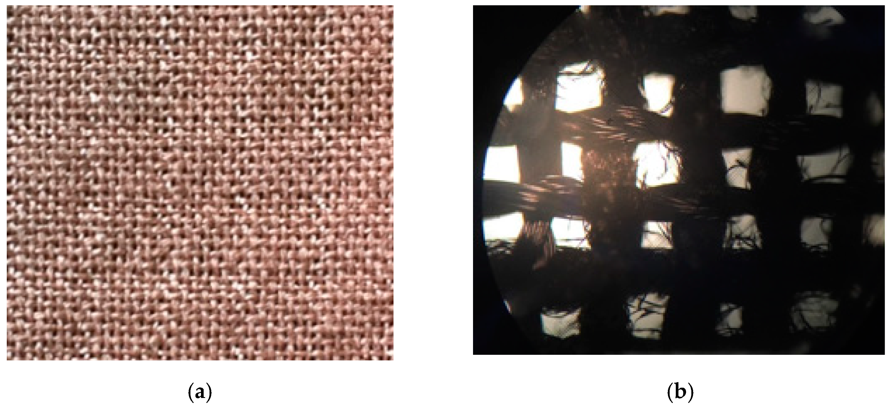
Optical microscopy images are evidencing the uniform covering of the fabric, both on cotton and the metallic yarns of the fabric structure (Figure 4a,b).
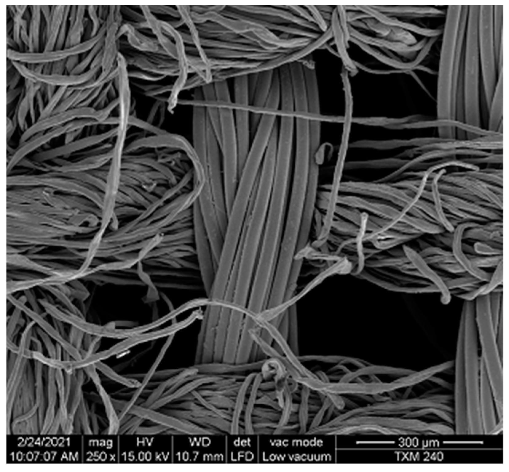
SEM images were meant to evidence the stainless steel and the silver yarns in the fabric structure (Figure 5 and Figure 6). The investigation of copper coated samples, presented in Figure 7, shows that the film is compact and covers the yarns uniformly. A rupture of the film along one fiber allowed evaluating the film thickness, with variations caused by the actual positioning into the field of view. Also, the copper coating seems to present a columnar structure of the deposit.
The SEM images reveal that the average distance between adjacent yarns is around 300 microns, while the distance between two adjacent metallic yarns is 5 mm. In this manner, a combined network of rectangles is formed: a small net originating from the first-order neighbors combining both cotton and metallic yarns, which are covered by copper coating, and larger rectangles formed by the metallic yarns woven into the fabric.
2.5. Electric Conductivity Measurements
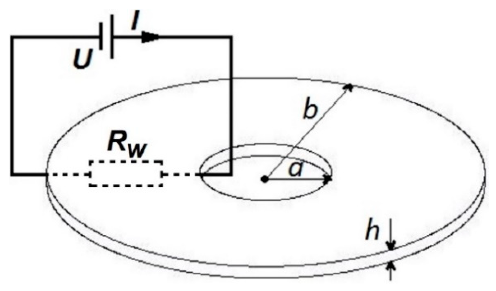
The following relation was used for measuring electric conductivity (σm) in the case of the washer geometrical shape of the textile shields, tailored according to the requirements imposed by the ASTM ES-07 standard for the determination of the EMSE.
where a is the inner diameter of the circle, b the outer diameter, h the fabric thickness and Rw—the measured resistance value by ohmmeter [Ω] (Figure 8).
2.6. EM Shielding Effectiveness Measurements
Electromagnetic shielding effectiveness (EMSE) measurement was accomplished according to the standard ASTM ES-07, via a transverse electromagnetic cell (TEM cell). EMSE is defined as:
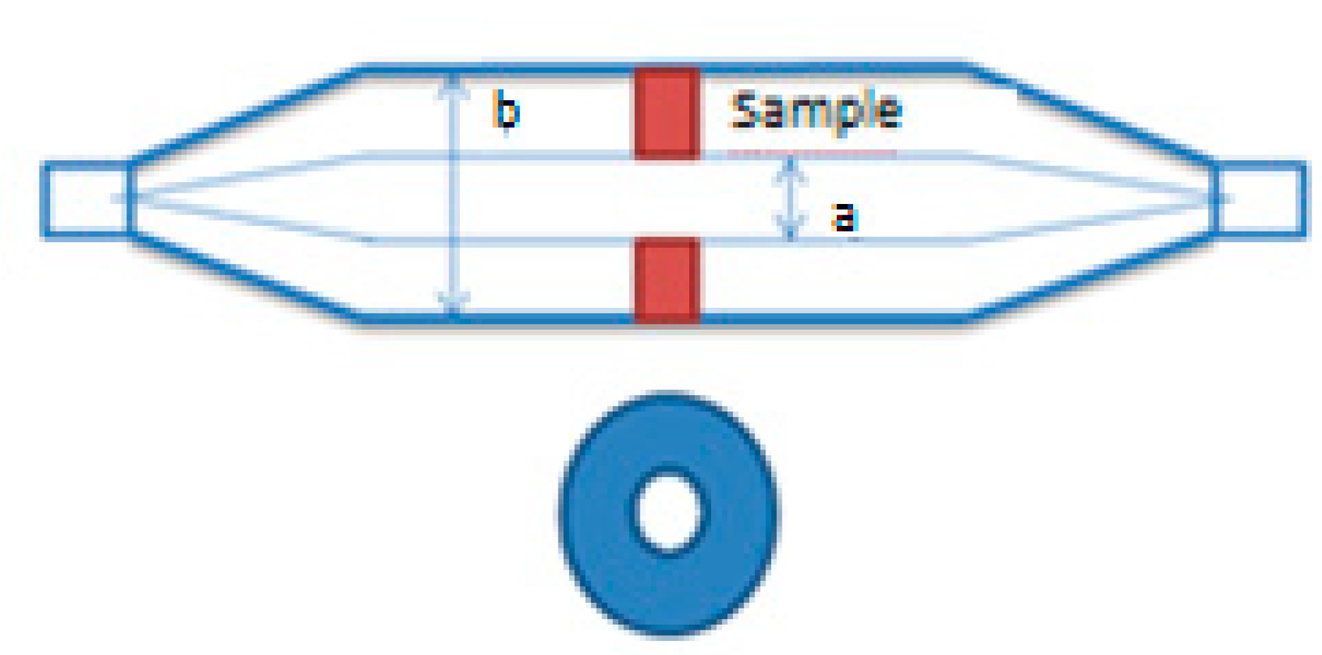
The scheme of the coaxial TEM cell is presented in Figure 9, which also includes the shape of the samples tailored for testing the EMSE with this system.
In order to be tested, fabric samples were tailored in annular shape having an outer diameter of 100 mm and an inner diameter of 30 mm and were fixed onto the cell by means of colloidal Ag paste applied on their borders. The measurement system included a signal generator Keysight E8257D, a power amplifier IFI model SMX50, the coaxial TEM cell model 2000 and an oscilloscope Tektronix model MDO3102. The EMSE measurements were performed within the frequency range of 100 kHz to 1 GHz, in accordance to the ASTM ES-07 standard. EMSE was measured for each of the seven fabric samples.
3. Results
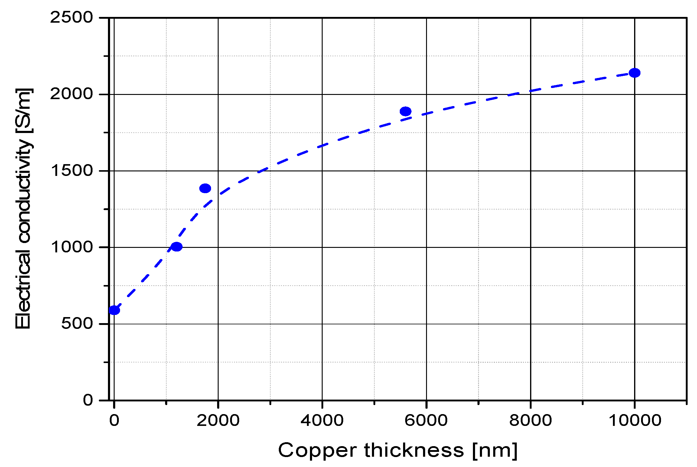
The results obtained for the electrical conductivity for the samples investigated according to the scheme depicted in Figure 2 are presented in Table 3. It is noticed that the conductivity of the fabrics containing silver yarns are systematically higher than those of the fabrics containing stainless steel yarns, with about one order of magnitude; at the same time, the conductivity increases upon copper coating of the fabrics, regardless of the type of yarns in the structure (Figure 10).
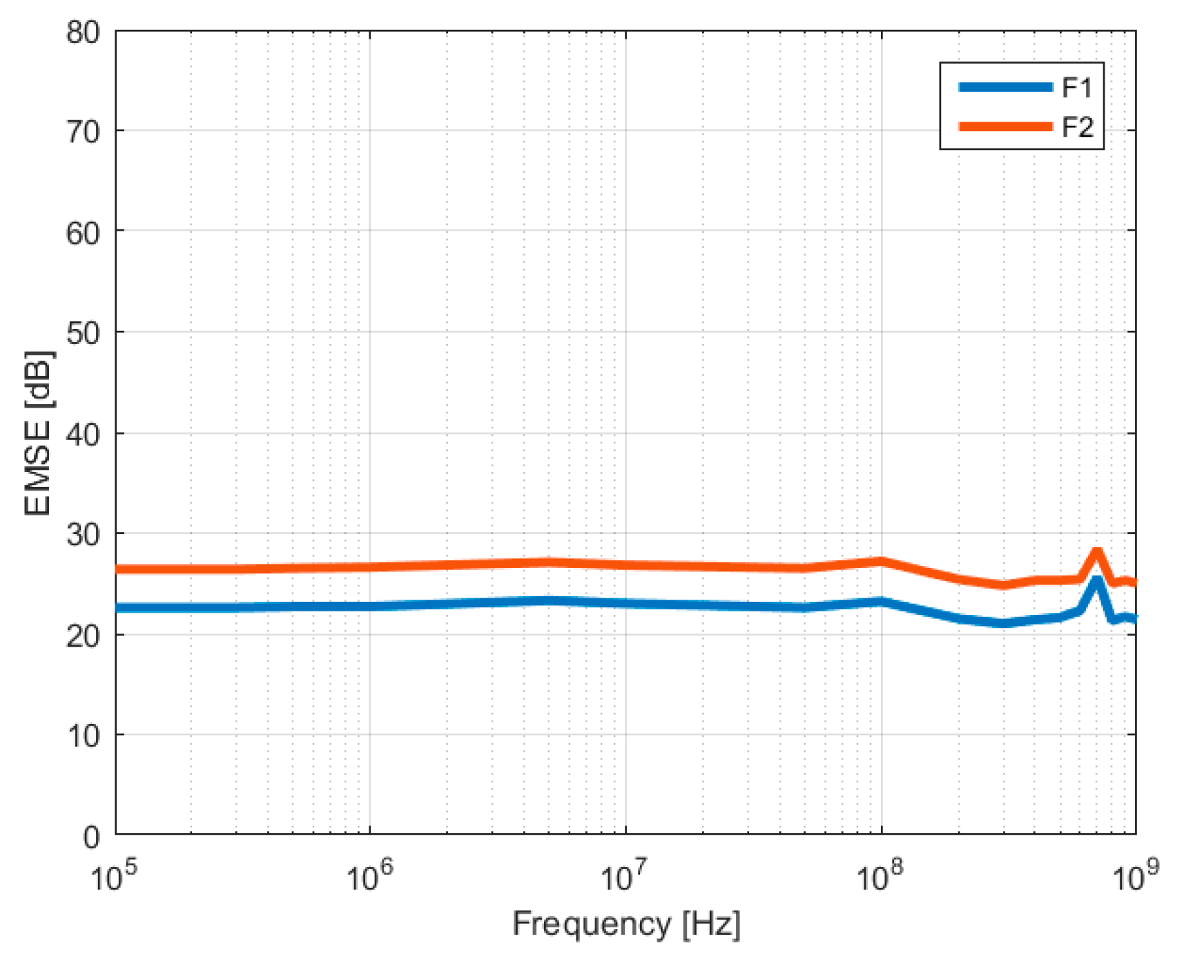
The graphs evidencing the electromagnetic shielding effectiveness in the case of stainless steel-based fabrics are illustrated in Figure 11. They show in the frequency range from 105 to 107 Hz a shielding up to 22 dB for the plain textile, with a small increase of around 4 dB of shielding upon coating with 1200 nm copper layer onto both faces of the material.
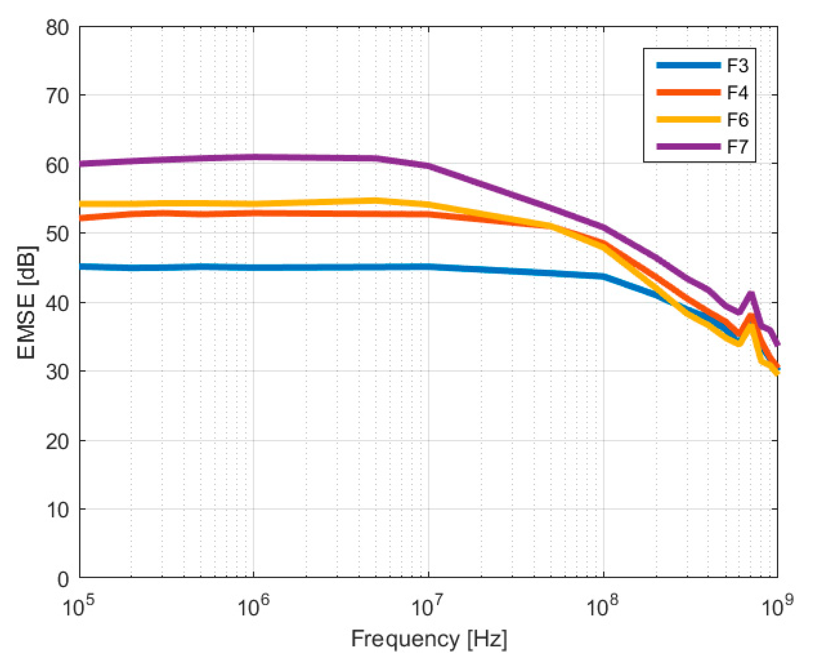
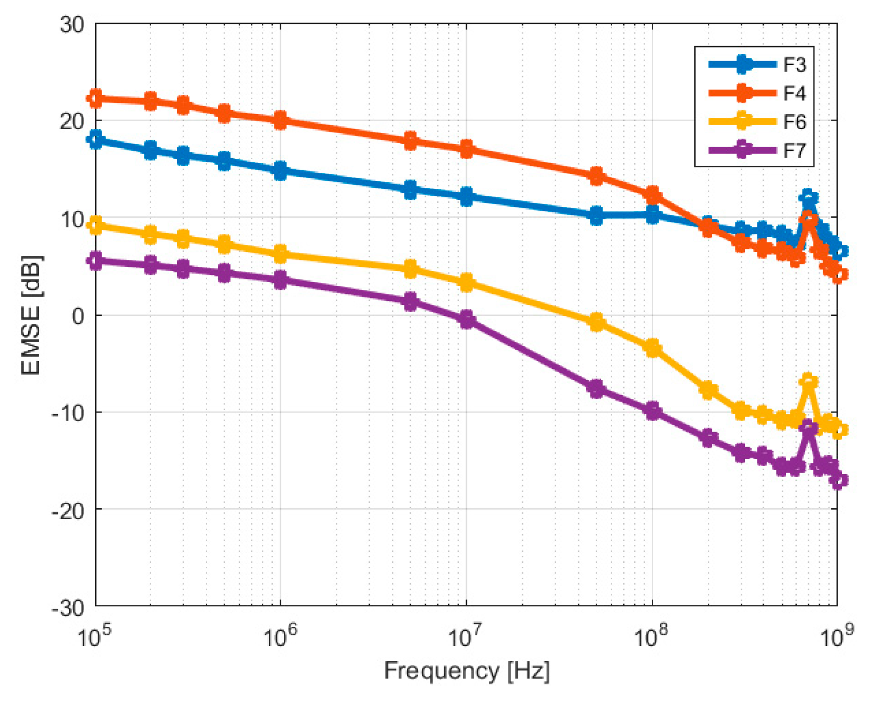
Figure 12 shows a comparison of the measured EMSE values for the silver-based fabrics, which exceed 45 dB for the frequency range from 105 to 108 Hz, even for the uncoated material. At the same time, one can notice that the additional coating of the structure is conducting to enhanced shielding effectiveness, which is more important as the copper coating thickness increases and present values exceeding 60 dB for 10 µm layer coating, for frequencies up to 107 Hz. At frequencies above 108 Hz, one can notice that the copper layer thickness has a limited influence on the shielding efficiency, which remain in the range 30–40 dB.
4. The Model for Estimating EMSE
The principle that states that for combinations of multiple electric shields, the overall EMSE is the sum of the EMSE of individual shields [19] was applied in order to model the shielding effectiveness of the fabrics with inserted conductive yarns and conductive coatings. As such, due to the fact that the structure of such shields includes the coating of one side, the fabric with inserted conductive yarns and the coating of the other side, the following relation is proposed for modelling of EMSE:
For EMSEgrid, the relation for electric conductive grid structures according to [19] and for EMSElayer, the relation of impedance method according to [13] are used. Geometric and electric parameters for both relations were applied related to the structure of the grid of inserted conductive yarns and the layer of coating. The following notations for electric and geometric parameters for these types of fabrics apply:
σy—electrical conductivity of the metallic yarns [S/m]
μy—magnetic permeability of the metallic yarns [H/m]
σm—electrical conductivity of the fabric material [S/m];
μm—magnetic permeability of the material (for copper coating μm∼μ0 = 4π ∗ 10−7 H/m);
h—fabric thickness [m]
d—diameter of the metallic yarn [m]
D—equivalent diameter of the electric conductor [m]
r—distance between conductive yarns [m]
t—thickness of the copper coating [m]
f—frequency of electromagnetic (EM) field [Hz]
For EMSEgrid, the model related to the woven fabrics with inserted metallic yarns, the following equation applies (4):
where:
Aa = attenuation introduced by a particular discontinuity, dB
Ra = aperture single reflection loss, dB
Ba = multiple reflection correction term, dB
K1 = correction term to account for the number of like discontinuities, dB
K2 = low-frequency correction term to account for skin depth, dB
K3 = correction term to account for the coupling between adjacent holes, dB
With following relations for these terms:
where:
h—fabric thickness (depth of opening) [m]
r = distance between conductive yarns (width of the rectangular opening perpendicular to E-field) [m]
where:
K is valid for rectangular apertures and plane waves.
where:
S—the area of each hole (sq cm)
n—number of holes/sq cm
where:
The term K2 is the single correction factor of the analytic relation sum which encounters the electric parameter of the yarns (electric conductivity and magnetic permeability), within the relation of skin depth. It is thus a factor with high sensitivity on the overall EMSE relation. The electric parameters were considered for the conductive yarn (not for the fabric), since the ratio p = D/δy is a property of the yarn. The skin depth of the yarn δy has the following electric parameters:
Since D is the diameter of the electric conductor and we have within the fabric structure two adjacent yarns (float repeat 2:6 Warp and 2:5 Weft), with the diameter d, the resulting diameter is: , due to the elliptical shape of the two adjacent metallic yarns. and with and dwe = fabric density in yarns/100 mm.
For EMSElayer, the model related to the shielding of the copper coating was given by the general expression of the impedance method according to [13]:
where:
δm—skin depth of copper coated fabric with inserted metallic yarns [m];
The following relations are set for the impedance of the textile shields () and the wave impedance of free space (Z0):
where:
ω = 2πf—angular frequency
Since the textile shields considered in this work contain metal coatings and yarns, the conductivity is assumed to be very large as compared with air, meaning that σm >> ωε. This condition is verified for the sample with lowest electric conductivity (F1) σm = 45.60 S/m (Table 3) and ωε0 = 0.0556 S/m for f = 1 GHz. Hence, the condition σ >> ωε is valid for all samples. The shield impedance can be written as:
In terms of skin depth of the coating, δm, the modulus of shield impedance is:
Skin depth is defined as the distance from the metal surface for which the current density drops at 1/e from the value at the inner surface. From (15) and (17), the definition of skin depth for copper coating is obtained:
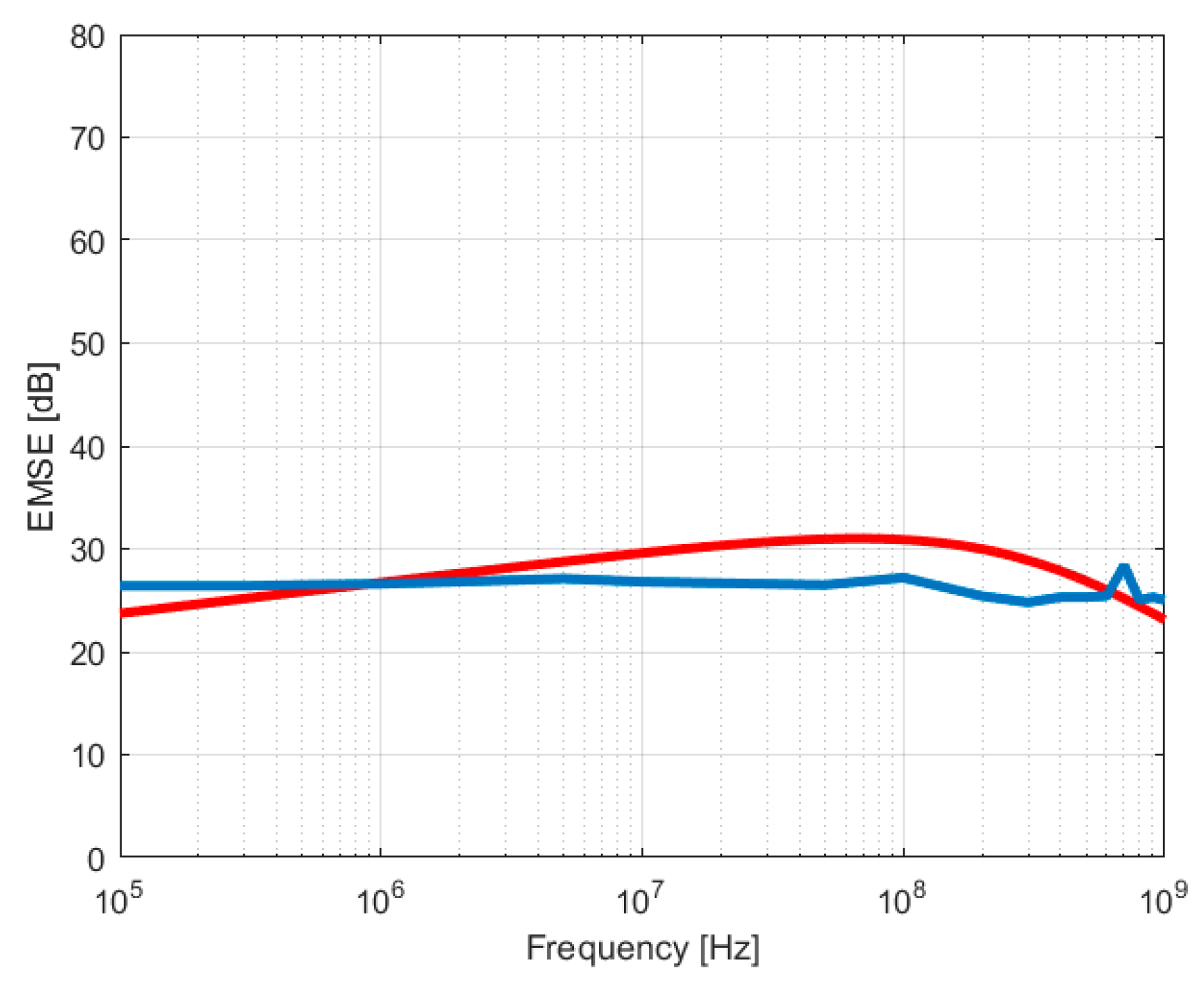
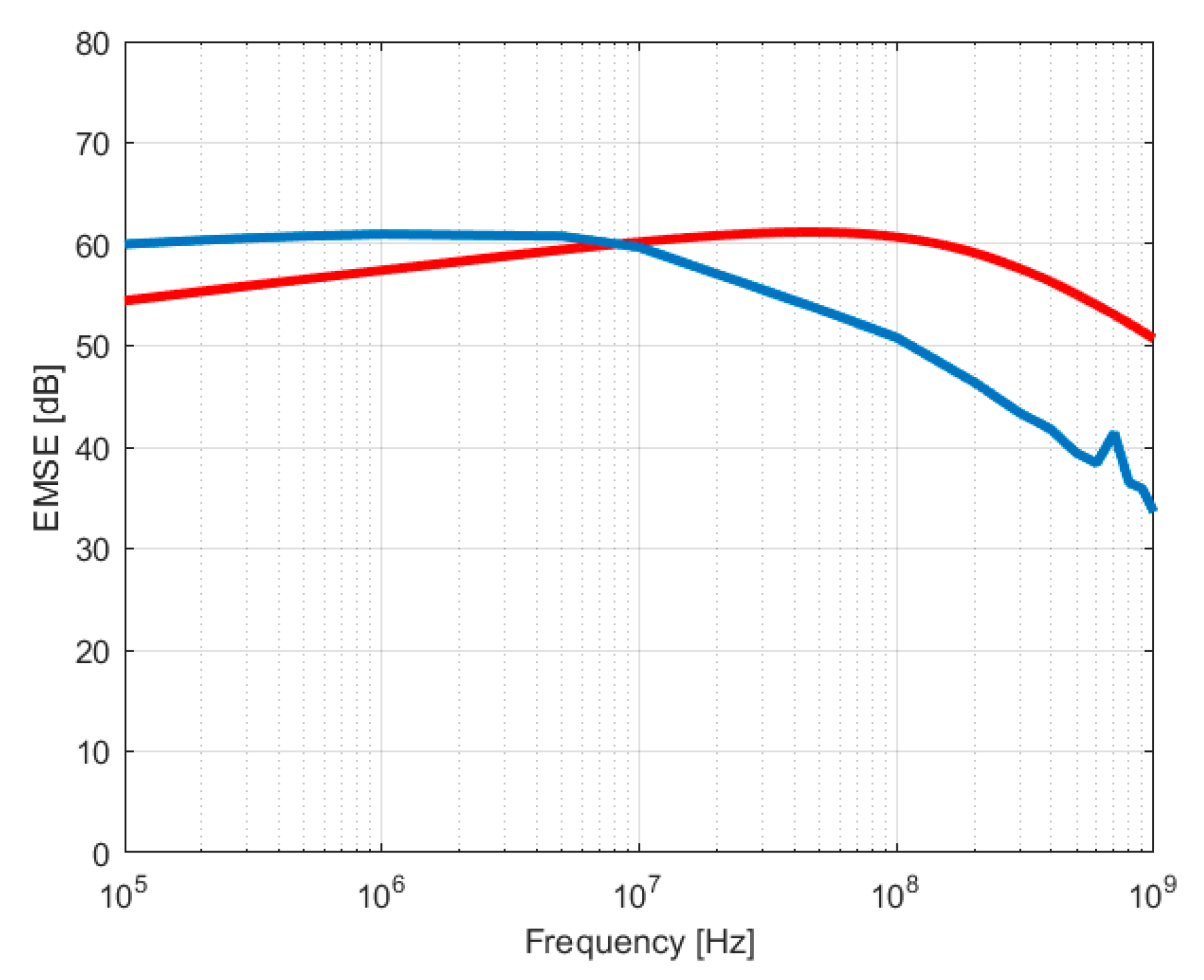
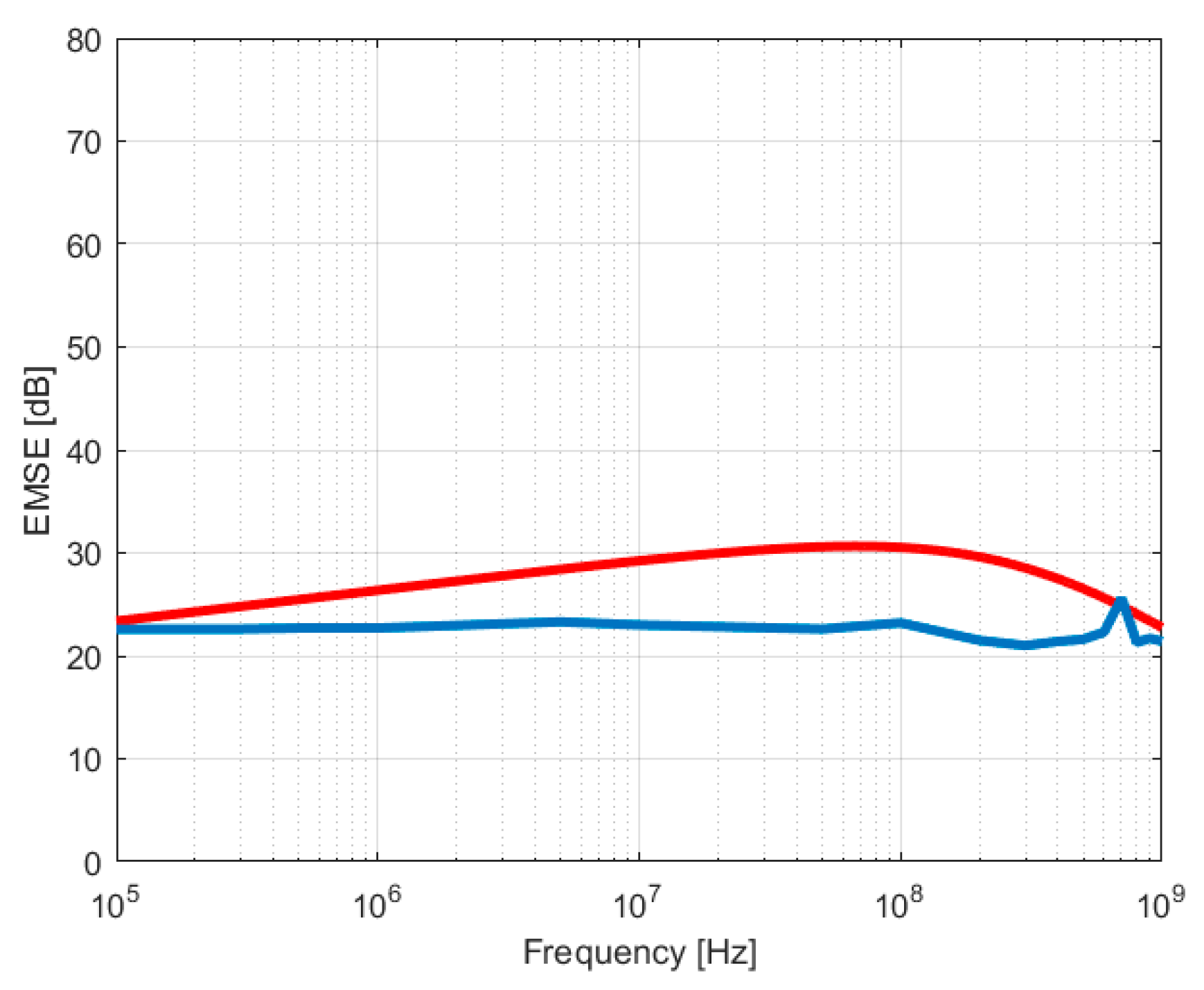
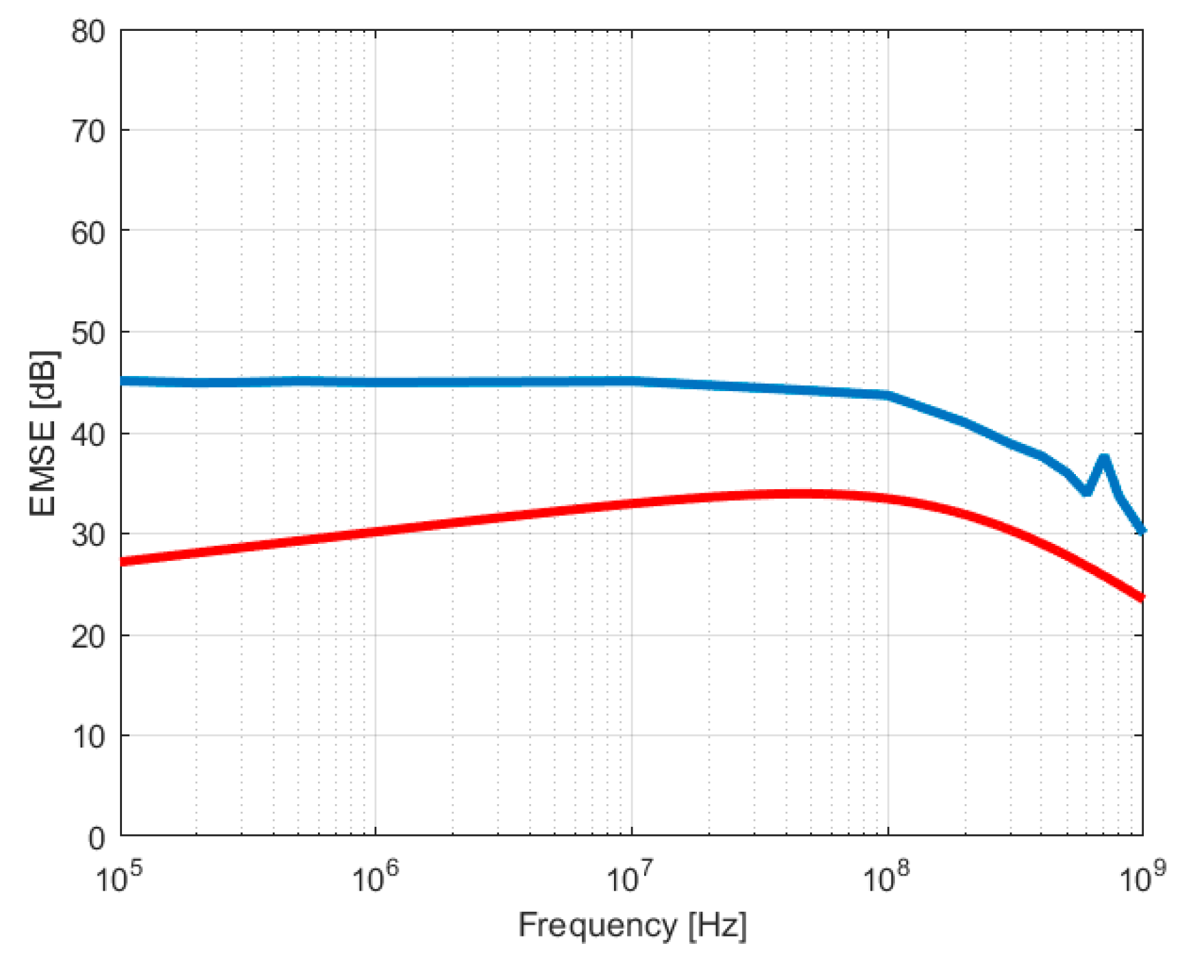
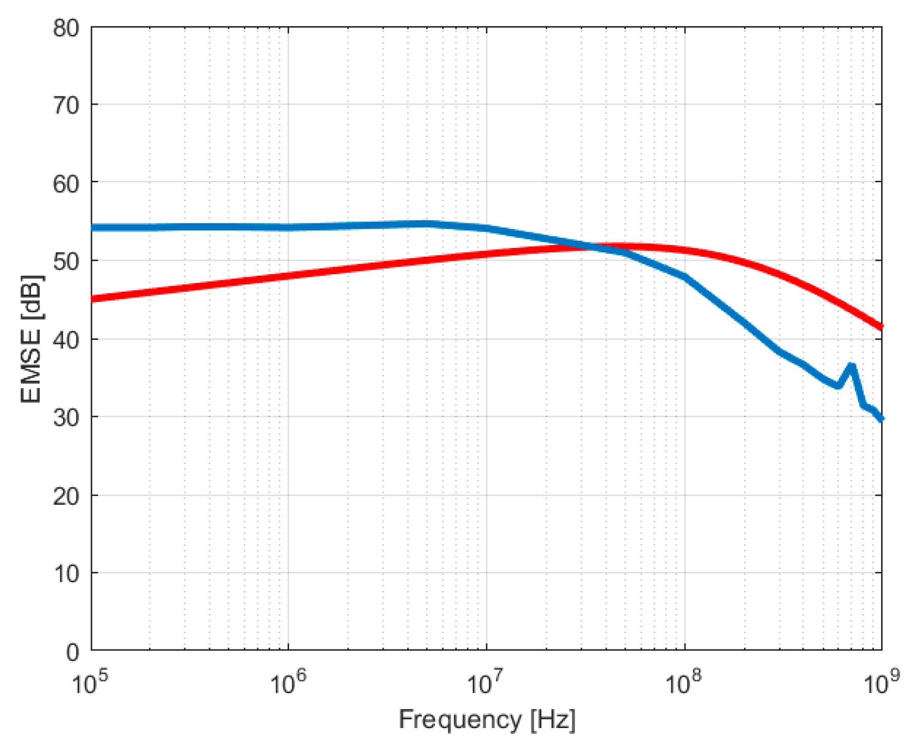
By applying the general Equation (3) for the calculation of EMSE for the samples involved in the present study, we obtained the red curves in Figure 13 and Figure 14 for the case of fabrics with inserted stainless steel yarns, and respectively the red curves in Figure 15, Figure 16, Figure 17 and Figure 18 for the case of fabrics with inserted silver yarns, and with different copper layer thickness.
5. Discussion
The novel structure of textile shields made of fabrics with inserted conductive yarns and metallic plasma coating has a geometry difficult to be modelled in order to accurately calculate the EMSE. Several analytic models have been applied in the planning phase of this research study, such as:
The proposed approach to model these structures was to add the EMSE of the three conductive structures: the metallic yarns inserted into the woven structure and the copper coating on both sides of the fabric.
The proposed analytic model considers both geometric and electrical parameters of the fabric with inserted conductive yarns and of the conductive coating. However, the analytic model distinguishes between the skin depth of the yarn (δy) and the skin depth of the fabric material (δm). Both electrical parameters for the skin depth (electric conductivity and magnetic permeability) were measured and calculated in the first phase for the metallic yarns and the coated fabrics. The geometric parameters with high sensitivity were the thickness of the fabric and the diameter of the metallic yarn. The equivalent diameter of the two metallic yarns was computed as the diameter of the circle having the same area as the resulting ellipse formed by the two adjacent metallic yarns in the fabric structure. The distance between the yarns was considered for computing the diameter of the ellipse, which was given by the fabric density (dw).
All geometric and electric parameters of the achieved shields were considered within proposed calculation of EMSE:
-
Electric conductivity and magnetic permeability of the metallic yarns;
-
Optical diameter of the metallic yarns and equivalent diameter of the electric conductor;
-
Distance between metallic yarns of the woven fabric, depending on float repeat and weave;
-
Electric conductivity and magnetic permeability of the fabric;
-
Fabric thickness;
-
Thickness of the plasma coated layer.
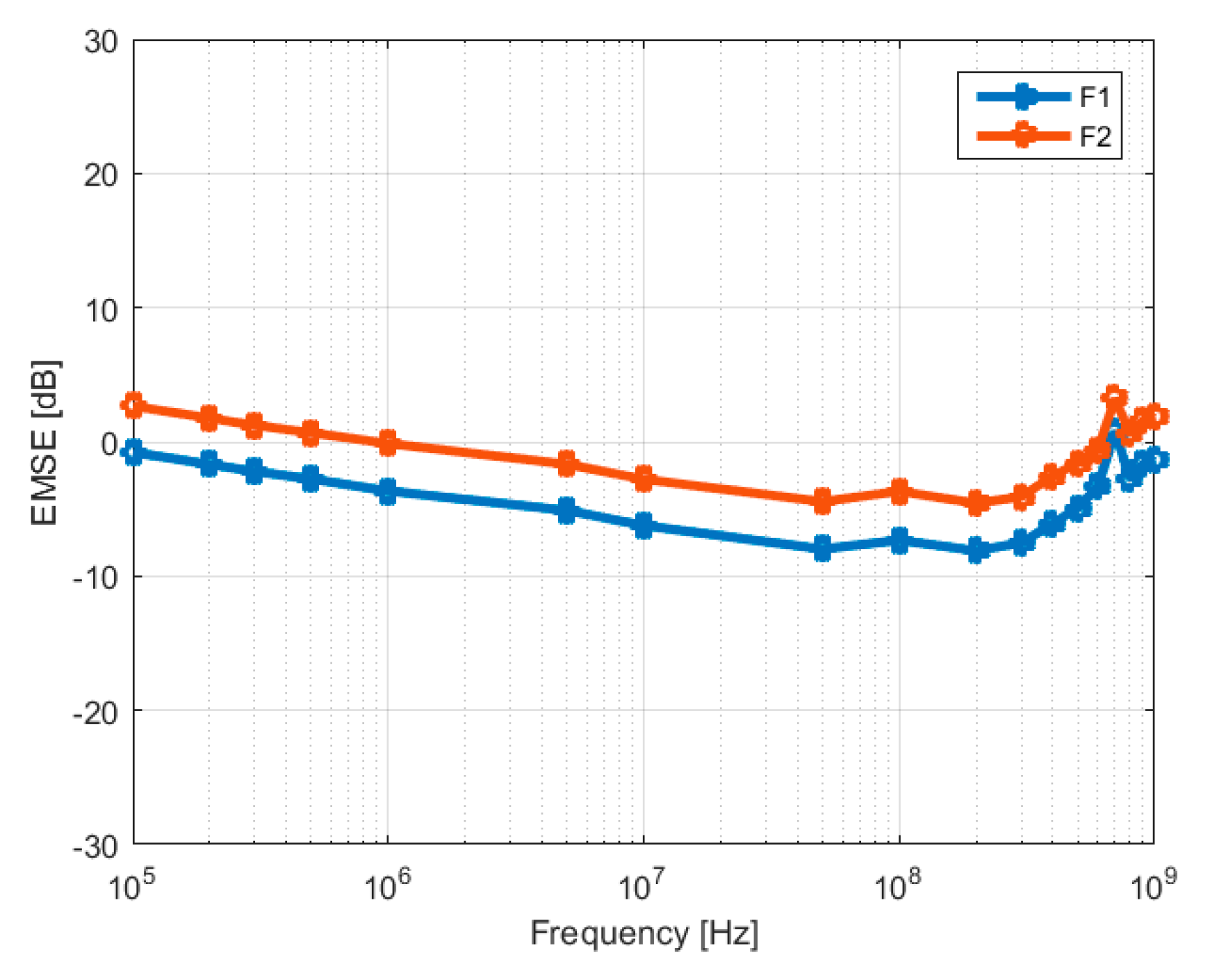
In the case of the fabrics with stainless steel yarns (F1), the model estimates quite well the fabric with inserted yarns, with differences in the range 1–8 dB over the whole frequency range. An even better fitting of the measured EMSE is obtained for the fabric with inserted yarns and copper coating (F2) by the EMSEgrid and the additional EMSElayer relation, with differences between the modelled and measured values less than 5 dB, as shown in Figure 19.
In case of the fabric with silver yarns (F3), the model EMSEgrid underestimates the measured values, a fact which could be explained by the two parameters with high sensitivity of the model—the electric conductivity and the equivalent diameter of the silver yarn. The electrical linear resistance of the silver yarn presented different values for different measurements, a fact explainable by its non-homogenous structure and the general terms of its specification (Rl < 1.5 kΩ/m) [25]. The measured value for silver yarn conductivity introduced into the model is a potential factor of underestimated values of EMSEgrid relation.
The fabrics F4 and F5 show a significant difference between modelled and measured values of around 20 dB on the frequency range 105 to 107 Hz, which could be explained by the low values of the EMSElayer model in case of 103 nanometer values: 1200 nm (F4) and 1750 nm (F5). On the other hand, the EMSElayer model has significant increasing values for 5600 nm (F6) and 10,000 nm (F7), which makes that EMSEtotal reaches the measured values for F6 and F7, as shown in Figure 20. These results show that the steady increase of the fabric conductivity upon copper coating, of 3.2 times for F6 and 3.6 times for F7 with respect to the uncoated fabric, plays an important role in the model of the EMSElayer. These facts suggest a significant role played by the conductivity of the components in the model. One has to consider that this type of composite EM shield is quite difficult to model and that the proposed relation of EMSE includes all the parameters of the electric structures of this composite shield.
The differences between the calculated and measured EMSE values (from Figure 19 and Figure 20) are due to the fact that the ideal conditions considered in the theoretical model, which is based on the isomorphism between the infinite plane shield placed in free space and the washer-shaped sample placed in a coaxial line, (homogenous material sample, perfect electrical contact between sample and sample holder (TEM Cell)) are difficult to achieve in practice. The electrical contact between the sample and sample holder becomes very important at high frequencies. Moreover, when using a coaxial TEM cell for determining the EMSE of material, higher transmission modes appear at high frequencies, which can affect the measurement results [11]. Also, given the composite structure of the proposed electromagnetic shields (textile yarns, conductive yarns, conductive coating), other phenomena may occur that would not usually occur in a perfectly homogenous material; these could affect the EMSE.
6. Conclusions
This paper proposes a novel type of textile shield: fabrics with inserted conductive yarns and metallic coating obtained by magnetron sputtering deposition. The results regarding the electromagnetic shielding efficiency (EMSE) of these fabrics evidence that the metallic plasma coatings applied additionally on fabrics with inserted conductive yarns contribute with 10–15 dB to overall EMSE in the frequency range 0.1–1000 MHz and therefore significantly enhance the material functionality. The utilization of flexible textile shields would open up new practical opportunities, and therefore the modelling of the electromagnetic shielding effectiveness (EMSE) is particularly important. As such, in the present paper, we considered the combinations of multiple electric shields originating from the initial fabrics structure with metallic yarns inserted and the coating of fabric on both faces with a conductive copper layer of various thicknesses.
Each of the contributions to the overall EMSE was analytically determined according to the equations 3–19, respectively EMSEgrid and EMSElayer, and the obtained values were computed to model the shielding effectiveness of the fabrics with inserted conductive yarns and conductive coatings. The approach of modelling is meant to be able to estimate the property of EMSE in the design phase of the textile shield. Although there are still differences between calculated and measured results, it is considered that the analytic model based on adding the particular contribution to EMSE of the metallic grid and of the metallic coating gives a valuable guidance when designing this type of textile shield.
Author Contributions
Conceptualization: I.R.R., Methodology: B.M., I.R.R., Software: I.R.R., M.C., Validation: M.C., B.M., Formal analysis: R.S., L.S., C.M., C.C., Investigation: L.S., C.M., R.S., Resources: L.S., B.M., Data curation: C.M., C.C., Writing original draft preparation: I.R.R., writing review and editing: B.M., R.S., M.C., Visualization: B.M., C.C., Supervision: I.R.R., Project administration: B.M., L.S., I.R.R., Funding aquisition: B.M., L.S., I.R.R., All authors have agreed to the published version of the manuscript.
Funding
This research was funded by ERA-NET Manunet project Contract no. 28/2018 TexEMFiRe—“Manufacturing textiles with elec-tromagnetic shielding and fire-retardant properties by plasma based methods”.
Research work for this study has been performed within ERA-NET Manunet project Contract no. 28/2018 TexEMFiRe—“Manufacturing textiles with electromagnetic shielding and fire-retardant properties by plasma based methods”, Contract no. PN19310103/2019—“Micro and nano-structured materials, processes and systems with applications in emerging technologies” and PN19150101- Emerging research on lasers, plasma, radiation and their applications in the fields of smart specialization and public interest.
Conflicts of Interest
The authors declare no conflict of interest.
References
Thomassin, J.M.; Jerome, C.; Pardoen, T.; Bailly, C.; Huynen, I.; Detrembleur, C. Polymer/carbon based composites as electromagnetic interference (EMI) shielding materials. Mater. Sci. Eng. R2013, 74, 211–232. [Google Scholar] [CrossRef]
Apollonio, F.; Liberti, M.; D’Inzeo, G.; Tarricone, L. Integrated models for the analysis of biological effects of EM fields used for mobile communications. IEEE Trans. Microw. Theory2000, 48, 2082–2093. [Google Scholar]
Islam, M.T.; Alam, M.S. Design of high impedance electromagnetic surfaces for mutual coupling reduction in patch antenna array. Materials2013, 6, 143–155. [Google Scholar] [CrossRef] [PubMed]
Ozena, M.S.; Sancakc, E.; Soin, E.; Shah, T.H.; Siores, E. Investigation of electromagnetic shielding effectiveness of needle punched nonwoven fabric produced from conductive silver coated staple polyamide fibre. J. Text. Inst.2015, 107, 912–922. [Google Scholar] [CrossRef]
Bi, S.; Zhao, H.; Hou, L.; Lu, Y. Comparative study of electroless co-Ni-P plating on Tencel fabric by Co0-based and Ni0-based activation for electromagnetic interference shielding. Appl. Surf. Sci.2017, 419, 465–475. [Google Scholar] [CrossRef]
Badic, M.; Marinescu, M.J. The failure of coaxial TEM cells ASTM standards methods in H.F. range. In Proceedings of the 2002 IEEE International Symposium on Electromagnetic Compatibility, Minneapolis, MN, USA, 19–23 August 2002; Volume 1, pp. 29–34. [Google Scholar] [CrossRef]
Ott, H.W. Introduction to Electromagnetic Compatibility; WILEY-Interscience: Hoboken, NJ, USA, 2009. [Google Scholar]
Kaden, H. Wirbelstroeme und Schirmung in der Nachrichtentechnick; Springer: Berlin/Heidelberg, Germany, 1959. [Google Scholar]
White, D. EMC Handbook. In A Handbook Series on Electromagnetic Interference and Compatibility; Don White Consultants Publishing: Gainesville, VA, USA, 1981; Volume 6. [Google Scholar]
Velten, K. Mathematical Modeling and Simulation: Introduction for Scientists and Engineers; Wiley-VCH: Hoboken, NJ, USA, 2008. [Google Scholar]
Ziaja, J.; Jaroszewski, M. EMI shielding using composite materials with plasma layers. In Electromagnetic Waves; InTechOpen: London, UK, 2011; p. 425. [Google Scholar]
Bernhard, E.K. Principles of Electromagnetic Compatibility; Artech House: Dedham, MA, USA, 1987. [Google Scholar]
Neelakanta, P.S. Handbook of Electromagnetic Materials: Monolithic and Composite Versions and Their Applications; CRC Press: Boca Raton, FL, USA, 1995. [Google Scholar]
Neruda, M.; Vojtech, L. Electromagnetic shielding effectiveness of woven fabrics with high electrical conductivity: Complete derivation and verification of analytical model. Materials2018, 11, 1657. [Google Scholar] [CrossRef] [PubMed] [Green Version]
Rybicki, T. EMI Shielding and reflection from textile mesh grids compared with analytic models. IEEE Trans. Electromagn. Compat.2018, 61, 372–380. [Google Scholar] [CrossRef]
Caro, A.L.; Vojtech, L. Modelling of Textile Reinforced Composites Barriers against Electromagnetic Radiation; TU Prague: Prague, Czech Republic, 2011. [Google Scholar]
Rădulescu, I.R.; Surdu, L.; Visileanu, E.; Costea, M.; Pătru, I.; Voicu, V. Modelling and testing the electromagnetic near field shielding effectiveness achieved by woven fabrics with conductive yarns. Ind. Text.2018, 69, 169–176. [Google Scholar]
Figure 1.
Sketch of the experimental set-up in INFLPR utilized for copper coating of textiles.
Figure 1.
Sketch of the experimental set-up in INFLPR utilized for copper coating of textiles.
Figure 2.
Textile samples considered for the validation of analytical model of EMSE.
Figure 2.
Textile samples considered for the validation of analytical model of EMSE.
Figure 3.
Scheme of the woven fabric with inserted metallic yarns and plasma coating.
Figure 3.
Scheme of the woven fabric with inserted metallic yarns and plasma coating.
Figure 4.
(a) Macroscopic aspect and (b) optical microscope image at magnification 50× for the woven cotton fabric with inserted silver yarns and copper coating of 5600 nm—F6.
Figure 4.
(a) Macroscopic aspect and (b) optical microscope image at magnification 50× for the woven cotton fabric with inserted silver yarns and copper coating of 5600 nm—F6.
Figure 5.
SEM image of fabric with inserted stainless steel yarns F1 (250×).
Figure 5.
SEM image of fabric with inserted stainless steel yarns F1 (250×).
Figure 6.
SEM image of fabric with inserted silver yarns and copper coating of 5600 nm F6—(250×).
Figure 6.
SEM image of fabric with inserted silver yarns and copper coating of 5600 nm F6—(250×).
Figure 7.
SEM image of fabric with inserted silver yarns and copper coating of 5600 nm F6. (a) (2000×) and (b) (8000×).
Figure 7.
SEM image of fabric with inserted silver yarns and copper coating of 5600 nm F6. (a) (2000×) and (b) (8000×).
Figure 8.
Geometrical (washer) shape of textile shield for standard ASTM ES-07.
Figure 8.
Geometrical (washer) shape of textile shield for standard ASTM ES-07.
Figure 9.
Scheme of the TEM cell and of the testing woven fabric sample.
Figure 9.
Scheme of the TEM cell and of the testing woven fabric sample.
Figure 10.
Dependence of the electrical conductivity of the fabrics with inserted silver yarns on the thickness of copper layer. The dot curve is just for eye guiding for the obtained trend.
Figure 10.
Dependence of the electrical conductivity of the fabrics with inserted silver yarns on the thickness of copper layer. The dot curve is just for eye guiding for the obtained trend.
Figure 11.
Measured EMSE for samples with stainless steel yarns (F1–F2).
Figure 11.
Measured EMSE for samples with stainless steel yarns (F1–F2).
Figure 12.
Measured EMSE for samples with silver yarns (F3–F7).
Figure 12.
Measured EMSE for samples with silver yarns (F3–F7).
Figure 13.
Calculated (red) and measured (blue) values for F1 (stainless steel yarns).
Figure 13.
Calculated (red) and measured (blue) values for F1 (stainless steel yarns).
Figure 14.
Calculated (red) and measured (blue) values for F2 (st. steel yarns) and 1200 nm copper coating.
Figure 14.
Calculated (red) and measured (blue) values for F2 (st. steel yarns) and 1200 nm copper coating.
Figure 15.
Calculated (red) and measured (blue) values for F3 (silver yarns).
Figure 15.
Calculated (red) and measured (blue) values for F3 (silver yarns).
Figure 16.
Calculated (red) and measured (blue) values for F4 (silver yarns) and 1200 nm copper coating.
Figure 16.
Calculated (red) and measured (blue) values for F4 (silver yarns) and 1200 nm copper coating.
Figure 17.
Calculated (red) and measured (blue) values for F6 (silver yarns) and 5600 nm copper coating.
Figure 17.
Calculated (red) and measured (blue) values for F6 (silver yarns) and 5600 nm copper coating.
Figure 18.
Calculated (red) and measured (blue) values for F7 (silver yarns) and 10,000 nm copper coating.
Figure 18.
Calculated (red) and measured (blue) values for F7 (silver yarns) and 10,000 nm copper coating.
Figure 19.
Difference between measured and calculated values for fabrics with stainless steel yarns and copper coating.
Figure 19.
Difference between measured and calculated values for fabrics with stainless steel yarns and copper coating.
Figure 20.
Difference between measured and calculated values for fabrics with silver yarns and copper coating.
Figure 20.
Difference between measured and calculated values for fabrics with silver yarns and copper coating.
Table 1.
Physical and electrical parameters for the yarns of woven fabrics.
Table 1.
Physical and electrical parameters for the yarns of woven fabrics.
Parameters/Yarns
Raw Material
Linear Density
Linear Electric Resistance, Rl [Ω/m] *
Linear Electric Conductivity, σy [S/m] *
Relative Magnetic Permeability, μry (according to [16])
Radulescu, I.R.; Surdu, L.; Scarlat, R.; Constantin, C.; Mitu, B.; Morari, C.; Costea, M.
Modelling the Woven Structures with Inserted Conductive Yarns Coated with Magnetron Plasma and Testing Their Shielding Effectiveness. Textiles2021, 1, 4-20.
https://0-doi-org.brum.beds.ac.uk/10.3390/textiles1010002
AMA Style
Radulescu IR, Surdu L, Scarlat R, Constantin C, Mitu B, Morari C, Costea M.
Modelling the Woven Structures with Inserted Conductive Yarns Coated with Magnetron Plasma and Testing Their Shielding Effectiveness. Textiles. 2021; 1(1):4-20.
https://0-doi-org.brum.beds.ac.uk/10.3390/textiles1010002
Chicago/Turabian Style
Radulescu, Ion Razvan, Lilioara Surdu, Razvan Scarlat, Catalin Constantin, Bogdana Mitu, Cristian Morari, and Marian Costea.
2021. "Modelling the Woven Structures with Inserted Conductive Yarns Coated with Magnetron Plasma and Testing Their Shielding Effectiveness" Textiles 1, no. 1: 4-20.
https://0-doi-org.brum.beds.ac.uk/10.3390/textiles1010002
Article Metrics
No
No
Article Access Statistics
For more information on the journal statistics, click here.
Multiple requests from the same IP address are counted as one view.
Radulescu, I.R.; Surdu, L.; Scarlat, R.; Constantin, C.; Mitu, B.; Morari, C.; Costea, M.
Modelling the Woven Structures with Inserted Conductive Yarns Coated with Magnetron Plasma and Testing Their Shielding Effectiveness. Textiles2021, 1, 4-20.
https://0-doi-org.brum.beds.ac.uk/10.3390/textiles1010002
AMA Style
Radulescu IR, Surdu L, Scarlat R, Constantin C, Mitu B, Morari C, Costea M.
Modelling the Woven Structures with Inserted Conductive Yarns Coated with Magnetron Plasma and Testing Their Shielding Effectiveness. Textiles. 2021; 1(1):4-20.
https://0-doi-org.brum.beds.ac.uk/10.3390/textiles1010002
Chicago/Turabian Style
Radulescu, Ion Razvan, Lilioara Surdu, Razvan Scarlat, Catalin Constantin, Bogdana Mitu, Cristian Morari, and Marian Costea.
2021. "Modelling the Woven Structures with Inserted Conductive Yarns Coated with Magnetron Plasma and Testing Their Shielding Effectiveness" Textiles 1, no. 1: 4-20.
https://0-doi-org.brum.beds.ac.uk/10.3390/textiles1010002


 ,
, 


