
An Overview on Methods for Producing Side-Emitting Polymer Optical Fibers


Institut für Textiltechnik, RWTH Aachen University, Otto-Blumenthal-Straße 1, 52074 Aachen, Germany
*
Author to whom correspondence should be addressed.
Textiles 2021, 1(2), 337-360; https://0-doi-org.brum.beds.ac.uk/10.3390/textiles1020017
Submission received: 1 August 2021
/
Revised: 31 August 2021
/
Accepted: 1 September 2021
/
Published: 7 September 2021
(This article belongs to the Special Issue Fibrous Materials (Textiles) for Functional Applications)
Abstract
:An overview of the most important methods for producing side-emitting polymer optical fibers is given. Based on a systematic literature and patent search, the methods that are applied in practice and explored in research are identified. The fabrication methods are classified into four groups according to the physical phenomenon that hinders total internal reflection: bulk scattering, bending, surface perforations and luminescence. Subdivisions are made regarding the actual processing steps. The production methods are described in detail and discussed with respect to their customizability and applications.

1. Introduction
Polymer optical fibers (POF) have seen increasing interest in science and industry over the last 60 years since their introduction in the 1960s. Their typical applications are in short-distance data transfer, as sensors and for illumination purposes, with the focuses of their development and application changing over the years [1]. In so-called side-emitting POF (SE-POF), as a special form of POF, total internal reflection (TIR) is deliberately hindered and, thus, light leakage via the cladding of the fiber is induced [2]. This enables the use of POF for illumination purposes in which emitting light at the end of the fiber is not sufficient (e.g., in automotive or decorative lighting [3,4]) as well as innovative applications in the fields of medicine (e.g., antimicrobial applications for disinfection reasons and phototherapy [5,6,7,8]), security and military technology (e.g., protective waistcoats with localization of projectile entry or smart police uniforms [4,9]), fiber-optical sensing (e.g., fluid level sensors and MRI-compatible motion detection [10,11]) as well as for UV curing resins and adhesives [12,13]. As can be seen from the mentioned applications, SE-POF stand out from conventional lighting systems, such as LEDs or injection-molded light guides, due to various advantages: textile drapability and bendability, immunity to electromagnetic interferences, small required installation space due to low light guide thickness as well as the separation of light source and light emission [14,15].
The research progress in the field of POF has already been summarized in many review papers, such as [16,17] for POF fundamentals, [18] for production and spinning processes, [19,20,21] for dye-doped POF, [22] for POF gratings, [23,24] for multi-step index and graded index POF, [25,26,27,28,29] for sensor technology and applications, [30,31] for medical applications and [32] for illuminating textiles in general, including POF. To the best of the authors’ knowledge, no systematic review on side-emitting polymer optical fibers and their fabrication methods has been published. This review aims to close this gap in the vast field of scientific POF literature.
A major challenge for the production of SE-POF is the homogeneity of the emitted light over the length of the fiber to be illuminated. According to the Lambert–Beer law the transmitted optical power P is being attenuated exponentially with the fiber length z:
where P0 being the initial optical power and α being the attenuation coefficient, which mainly describes intrinsic losses here.
In addition to the inherent attenuation of the fiber, the homogeneity is further reduced by the power already emitted laterally, which is no longer available for further lateral emission, when a uniform sidelight activation process is considered. Mathematically, a uniform sidelight activation can be described as a constant length-related sidelight activation factor ηSE of the optical power P being emitted over a short length Δz of the fiber [2]:
where PSE,Δz is the side-emitted optical power per length at position z for a length of Δz of the fiber. This results in a differential equation of first order for the optical power transmitted over a length of Δz:
Equation (3) is a simple differential equation leading to an exponential loss by sidelight emission. Therefore, both attenuation losses and side emission losses can be described as exponential decays [33].
The challenge of homogeneous sidelight emission along the SE-POF—or at least a limited inhomogeneity of laterally emitted power within a particular fiber length depending on the application—limits the possible length of an SE-POF to only a few meters long at the most [34]. Strategies to extend the possible illumination lengths include using light sources at both ends of the fiber or adding a reflector at the distal end of fiber. In both cases, theoretically maximum lengths of SE-POF with given limited inhomogeneity can be calculated. However, these can only be used as an estimate, as deviations may result from unequal coupling efficiencies of the light sources or non-optimal reflectivity of the mirror depending on the application technique [35].
Another approach to homogenization is to adjust the sidelight activation along the fiber. When using a non-uniform sidelight activation, ηSE is no longer constant. Combining Equations (2) and (4) gives:
which shows that for constant laterally emitted power PSE, the sidelight activation factor ηSE needs to be varied along the fiber as a function of z. Equation (5) cannot be algebraically converted to ηSE. However, it can be solved numerically or—if the attenuation coefficient α is negligibly small as Spigulis et al. assume [33]—with the Lambert W function [36]. Since an exponential decay must be compensated by the stronger sidelight activation, a sharp increase in sidelight activation is necessary after a certain length. Depending on the process, certain increases are impossible to achieve or an excessive mechanical weakening of the fiber sets in. This limits this mechanism of extension of the homogeneous luminous length as well [33].
In order to generate a sidelight emission, various sidelight activation methods exist, which differ in terms of the underlying physical effect on the one hand, and the actual production process on the other hand. The effect of sidelight activation can be put on a par with creating refraction by hindering TIR. In terms of ray optics, TIR describes the reflection of light at the core–cladding-interface with a reflection angle θ (cf. Figure 1a) greater than the critical angle θcrit:
where n denotes the refractive index of the core or the cladding, respectively. Accordingly, there are basically three ways to prevent total internal reflection: increase the cladding refractive index, decrease the core refractive index or change the angle [37]. In practice, however, usually only the change of the angle is used: The approaches to change the reflection angle can be categorized as follows [13]:
- -
- Bulk scattering (cf. Figure 1c): Scattering centers can be intentionally integrated into the POF to change the light ray path. The scattering can be induced by adding substances or dopants such as microparticles or nanoparticles where the particles’ number, shape and refractive index influence the side emission. Scattering can also be inherent to the material, e.g., in case of Rayleigh scattering due to molecular irregularities [2,38,39].
- -
- Bending (cf. Figure 1d): Bends induce a displacement of the core–cladding interface, which again can cause a light ray to drop below the critical angle. Most of the light is emitted from the convex surface of the bent fiber. Side emission can be induced by both microbends where the bending radius R is in the range of the POF radius r or smaller, as in many textiles such as woven or knitted fabrics, or macrobends with R >> r [40,41,42].
- -
- Surface perforations (cf. Figure 1e): Irregularities at the core–cladding interface change the angle at which a light ray hits the reflective surface leading to refraction. The surface irregularities can vary from microperforations to even notches or grooves. The depth, number and geometry of the perforations influence the intensity and direction of the emitted light [43,44,45,46].
- -
- Luminescence (cf. Figure 1f): Unlike scattering particles, luminescent materials can change a light ray’s path by isotropically reemitting light that has previously been absorbed. With regard to POF, this means that a part of the light fulfils the condition of TIR and propagates further in the fiber core. Another part of the light rays does not fulfil the condition and is refracted [33,47].
Figure 1.
Reflection and refraction in optical fibers: (a) total internal reflection (TIR) from axial view, (b)TIR from cross-sectional view, (c) refraction due to bulk scattering, (d) refraction due to bending, (e) refraction due to surface perforations and (f) refraction due to luminescence.
Figure 1.
Reflection and refraction in optical fibers: (a) total internal reflection (TIR) from axial view, (b)TIR from cross-sectional view, (c) refraction due to bulk scattering, (d) refraction due to bending, (e) refraction due to surface perforations and (f) refraction due to luminescence.

After the methodology for the literature and patent research is described in Section 2, the actual sidelight activation processes are described in Section 3. The fabrication methods are categorized with regard to the physical phenomenon hindering TIR, as described above. For bulk scattering and surface perforations, the processes are further subdivided regarding the actual procedures. In Section 4, the results are summarized.
2. Methodology
In this chapter, the identification, selection, screening, and analysis process of the available literature is described. To find as many relevant patents and papers as possible, a structured database search with keywords was carried out. Two researchers were involved in the selection process. The research was conducted in February 2021. The database used for the patent and literature search is Scopus. The keywords used are formed as shown in Figure 2. The search operator “AND” was used to link the basic and the specific search strings. The specific search strings were connected using the “OR” operator. For the literature search, the specific search strings from both categories were used. For the patent search, only the first was used, because else the number of the search results would have been unmanageably high.
Overall, 433 patents and 1394 papers were found. At first, the titles, journal names, and patent classifications were scanned. A total of 1408 patents and papers were excluded as a result, because their content was not related to side-emitting polymer optical fibers. Next, the researchers scanned the abstracts or claims to identify papers and patents describing the fabrication of side-emitting polymer optical fibers. Publications, for example, that focus on applications rather than on the production were screened out. After the screening step, 186 patents and papers were found to match the covered topic, out of which a total of 106 different publications were used for this paper based on their content (cf. Table 1).
3. Fabrication Methods for Side-Emitting Polymer Optical Fibers
Based on the patent and literature research, the methods for sidelight activation of POF are divided into the four main areas of bulk scattering, surface perforation, bending and luminescence. For each of these areas, the physical principles and the specific manufacturing processes are explained.
3.1. Bulk Scattering
One possibility to realize a radial light emission is the doping of the POF with scat-tering particles or a targeted insertion of defects into the fiber. In the case of doping by scattering particles, both cladding and core doping are possible. The insertion of defects is feasible by using a femtosecond laser [33,48]. While the use of scattering particles is directly implemented in the POF manufacturing process, the treatment using the femtosecond laser is an additional and subsequent process.
Various organic or inorganic materials that have good light scattering properties can be used as scattering particles. These include metal oxides such as zinc oxide (ZnO), magnesium oxide (MgO), titanium dioxide (TiO2) or aluminum oxide (Al2O3) [39,49], and synthetic materials such as silicone resin-, styrene- or acrylic-based particles [50,51]. The size of the inserted microparticles varies between 50 and 2000 nm, so that both Rayleigh scattering and Mie scattering can occur [50]. Rayleigh scattering occurs when the particle diameter is small compared to the wavelength of the light. The distribution of Rayleigh scattering is symmetrical to the particle and highly correlated in propotion to the wavelength to the minus fourth power. Mie scattering occurs when the particle diameter is equal or higher to the wavelength of light and is, to a good approximation, wavelength independent. The distribution of the scattered light is asymmetric to the particle with a highly forward orientation [38,52,53].
A typical source of transmission loss in standard SI-POF for data transmission is the fiber core’s slight ellipticity, which causes scattering losses as well as air bubbles, fissures or dust in the core or cladding [16]. Therefore, sidelight POF can also be produced directly in the spinning process where scattering is intentionally incorporated in the fiber, as can be seen in the PS series of Toray Industries, Inc., Tokyo, Japan. Furthermore, sidelight POF can be produced directly in the spinning process without scattering particles. POFs with a plurality of cores and an enclosing cladding, so-called multicore POF, are used for this purpose. The number of cores spun out and their cross-sectional shape have an influence on the irradiation characteristic of the side-emitted light, as can be seen in the VB series of Asahi Kasei Corporation, Tokyo, Japan. The microscopy image of the cross section of VB-1000 with and without guided light can be seen in Figure 3. It is clear from the microscopy image that the individual fiber cores are not circular. The only exception is the fiber core in the center. The cores surrounding this one (“first level”) all have the same shape. The cores on the second level repeat in a pattern of two. The cores on the third level repeat in a pattern of three. A number of patents address multicore fiber assemblies. However, these multicore fibers often are not used as sidelight fibers, but for other applications, including endoscopes [54,55].
3.1.1. Doping of the Fiber
For the production of a core-doped POF, scattering particles, as specified in Section 3.1, are compounded into the optical polymer. Figure 4 above illustrates this compounding process exemplarily. In the process, the optical polymer granules are added to an extruder, melted and mixed with the scattering particles in a molten phase. It is evident that the ratio of polymer to scattering particles as well as the type and size of the scattering particles can be varied (within the limits of the process). A conveyor belt supports the cooling and drying process. The extrudate of polymer and scattering particles is then granulated [37].
The second step is the bicomponent melt spinning process of the core–cladding fiber (cf. Figure 4 below). For this, the compound of polymer and scattering particles is added to the core extruder and, typically, a fluorinated polymer is added to the cladding extruder. Both materials are melted and conveyed through the spinneret by a spinning pump at constant pressure. The core–cladding fiber that emerges from the nozzle is cooled in a water bath and drawn in a heater. In addition to the continuous melt spinning process described in detail here, particles can also be incorporated via other continuous production processes such as continuous extrusion and photochemical polymerization, or via discontinuous production processes including heat-drawing and batch extrusion [18].
Strategies to enhance sidelight homogeneity via varying the nanoparticle concentration over the fiber length have been described. However, according to the withdrawn or fee-related expired status of the relevant patents, they are not considered as industrially relevant [56,57].
For the production of a sidelight POF via doping the cladding, the compounding process is very similar as for the core-doped POF. The only difference is that the particles are not compounded into the core material but into the cladding material. In cladding doping, unlike in core doping, the light ray is scattered upon interaction at the core–cladding interface whenever contact with a scattering particle has occurred.
Sidelight activation by cladding doping is, e.g., possible with a metal oxide powder such as titanium dioxide (TiO2), bismuth subcarbonate (Bi2O2(CO3)) or a mixture thereof, with blending concentrations of 2 to 10%, according to [37,58]. Another possibility is the creation of a scattering layer between the fiber core and an outer cladding. The intermediate layer contains scattering particles, such as silicon dioxide (SiO2), barium oxide (BaO), magnesium oxide (MgO), diamond-like carbon or glass ceramic particles [59]. While, in this case, the radiation characteristics are uniform over the cross-section, a directed emission in one direction can be realized when only one segment of the circle is equipped with a scattering layer [60].
3.1.2. Laser Modification by In-Volume Processing
The use of ultrashort pulse durations in the femtosecond or picosecond range on polymers near isochoric heating leads to rapid adiabatic expansion [61]. If the laser is focused using a microscope objective, absorption of the laser energy is limited to the volume of the focal point. This enables the generation of three-dimensional hollow structures below the fiber surface [62]. The geometry and texture of the cavity and, therefore, the profile of surface activation in the fiber core depends on the laser power, the pulse energy, the number of pulses per interaction point and the distance between two interaction points. The inserted cavities act as refractive index disturbances in the core and scatter the incident light. As a result, a fraction of the light is emitted radially out of the fiber [62,63,64].
3.2. Surface Perforation
Imperfections in the previously smooth core–cladding interface create scattering that causes the light to refract and be partially emitted radially. Figure 5 shows different surface modification geometries that influence the side-emittance in various ways. The core–cladding imperfections can be microperforations (cf. Figure 5a), which barely penetrate the cladding and only impact a tiny part of the core, and thereby cause little scattering [2]. However, there can also be bigger notches, which emit a relatively higher proportion of the light (cf. Figure 5b).
In the case of a surface treatment that is not homogeneous across the fiber cross-section, i.e., one cross-section side with asymmetrically stronger perforation, a significantly stronger light emission can be detected on the side opposite the notch. Figure 5b shows an exemplary ray path for this effect [65]. This effect is also typical for planar optical waveguides and other injection-molded optical waveguides of arbitrary shape with a surface microstructure for lateral light emission [66]. In the case of POF, the surface treatment is usually performed equally over the whole circumference in order to equalize the emission intensity in all directions [58].
The direction of the notches relative to the fiber axis and light guiding direction also influences the light emission. If angled notches are inserted against the direction of light propagation, the larger proportion is emitted on the notch side (cf. Figure 5c) [58]. With notches in the opposite direction, the opposite effect can be created accordingly (cf. Figure 5d) [67]. In addition to the variation of the notch orientation relative to the fiber axis, the amount of light emitted laterally also depends on the broader notch geometry (cf. Figure 5e). Flat notch geometries result in a comparatively high proportion of TIR [43,65].
A gradual treatment of the POF to homogenize the emitted optical power over the fiber length is usually possible by surface treatment. Two approaches can be used here. In case of discrete notches, the distance between the notches can be reduced with increasing distance to the light source. By adjusting the notch density, the proportion of emittance can be modified to the optical power available for coupling out according to Equation (5). The second approach is to increase the notch areas with increasing distance from the light source by making the notches deeper. The enlarged notch surfaces lead to an increased proportion of light rays hitting the notches, which compensates for the loss of light. The two approaches can also be combined with each other (cf. Figure 5f). This is usually the case when small microperforations, instead of notches, are applied gradually [58,65].
The surface perforation can not only be applied in discrete notches or micro-perforations. Continuous perforations are also possible, e.g., one or more notches running in a spiraling manner along the fiber axis (cf. Figure 5g) [13,68]. With regard to the fiber axis, microperforated or notched fibers have locally variable cross-sections. They differ from non-circular fibers, which typically have a constant cross-sectional shape over the entire length of the fiber, although certain non-circular cross-sections, such as, e.g., a trilobal shape, can be considered as circular fibers with three axially long notches that also influence the amount and direction of light emittance [48].
The disadvantage of all surface perforation processes is the mechanical impact on the POF, which can lead to a reduction in tensile strength [41,46] and bendability [69], as well as a rough fiber surface [44,45,69,70], whereby the extent varies depending on the process and its parameters. Their main advantage is that fiber surface is treated subsequently to the actual spinning processes and, therefore, standard step-index POF can be used. Moreover, the surface modification can typically be conducted gradually to enhance the homogeneity of the side-emittance.
For each of the three surface treatment types, abrasive, chemical and thermal, an exemplary image is shown in Figure 6. The images are juxtaposed with the untreated reference fiber (cf. Figure 6a). All four images were taken with a laser confocal microscope. Figure 6b shows the surface of an abrasive-treated POF that was subjected to sandblasting. It can be seen that the notches represent a random but uniform damage. Figure 6c shows the surface with irregular damage of a POF treated in an acetone bath. Figure 6d shows the POF surface through the thermal treatment of laser ablation. The introduced cavity, which functions as an optical element, is evident.
Most commercially available step-index POFs have a core made of PMMA. Among others, polycarbonate, polystyrene, perfluorinated polymers or a variety of cyclo olefin copolymers are also used for POF production, but mainly for special fibers such as low-loss graded-index POF, scintillating fibers or special applications at higher temperatures [1,71]. The core materials are usually cladded with fluorinated polymers, which are particularly well suited as cladding materials due to their low attenuation and low refractive index. Other advantages include the chemical stability, the high temperature resistance and the low UV absorption. Examples of fluorinated polymers or copolymers used as cladding materials are polytetrafluoroethylene (PTFE) and trifluoroethyl polymethacrylate (PTFEMA) [72,73].
The materials of the fiber core and cladding influence the surface treatments, because, e.g., different materials have different absorption spectra for laser radiation, different solubilities for different solvents or also different scratch resistances. Unless otherwise stated, the results presented in the following refer to standard POF with PMMA in the core and a mostly unspecified fluorinated polymer in the cladding, which are used in most scientific and industrial applications.
3.2.1. Abrasive Material Removal
One possibility of mechanical surface perforation is sanding the fiber by lightly rubbing it with sandpaper so that both the core and the cladding are treated. The sanding process can be carried out either by hand or by a sanding machine [46]. Likewise, in the case of larger or asymmetric notches, milling cutters and circular disc-shaped tools with smooth, toothless blades can be used [67].
The most common abrasive activation method for POF is particle blasting, sometimes also referred to as sandblasting. In this process, the POF is guided through a chamber in which it is blasted by one or more jet nozzles. For this purpose, a strong air flow through a nozzle accelerates the particle material and transports it at high speed to the fiber. When it hits the fiber, the abrasive effect of the blasting medium leads to material removal. It is important to ensure that the abrasive is hard enough to damage the fiber material, which is why materials such as quartz, metal or corundum are common. Due to gravity, the particle material accumulates at the lower end of the blasting chamber and can be reused. Some of the particles can adhere to the roughened fiber surface and must be removed with, for example, an air knife [74,75,76].
For single fibers, this method is typically performed continuously, as exemplarily shown in Figure 7. By means of a degressive velocity profile during fiber input as well as by continuously adjusting the pressure of the blasting nozzle, which influences the particle velocity and, thus, their collision energy, abrasive irradiation can also be used to produce gradually activated SE-POF [74].
When using optical fibers as planar illumination elements (e.g., in a woven fabric with POF), CNC-controlled nozzles are typically used. The fabric stands still or is moved at a constant speed, whereas the nozzles’ blasting direction and the particle acceleration can be adjusted accordingly for a gradual treatment [77].
3.2.2. Chemical Surface Perforation
Another variant of surface modification can be realized by chemical treatment. Both etchants and solvents can be used. For both methods, the degree of surface modification depends on the chemical concentration, the treatment temperature and the exposure time [46].
During treatment with etchants, material degradation takes place through a chemical reaction between the molecules of the chemical and the molecules of the POF. The reaction is mostly an isotropic reaction. PMMA generally has low resistance to the alkaline etchants’ caustic potash and caustic soda lye, and is also not resistant to the acidic etchants’ nitric acid, sulphuric acid and hydrofluoric acid [78]. Therefore, a chemical activation with these etchants is possible. However, etchants are very rarely used for chemical surface perforation. The reason for this is that etchants usually react very aggressively and are extremely harmful to health. This makes handling more difficult. In addition, the use of etchants usually results in harmful hairline cracks during the treatment of POF [79,80].
When treating with a solvent, material removal is achieved by abolishing the lattice energy. Suitable solvents include tetrahydrofuran, ethyl acetate, acetone, n-hexane and chloroform. Surface modification by solvent use results in soft sidelight emission, a uniformly rough surface, and thus, acceptable homogeneity [45,81].
It is possible to carry out the surface modification discontinuously or continuously; the former is currently being investigated in the majority of cases. The application of the chemical can be realized by an impregnation process or by a spraying process. In the spray process, the untreated POF is wetted by finely dispersed droplets of the chemical [82]. The chemical is then removed from the POF by wiping or a water bath. One conceivable possibility for the continuous impregnation process is shown in Figure 8. In this case, the untreated POF is drawn from a spool over guide rollers through a chemical bath. The impregnated POF is then passed through a water bath and, thus, freed from excess chemical. The water bath thus ensures a defined exposure time of the chemical. The wiper unit between the chemical bath and the water bath ensures that the chemical does not contaminate the water. A further stripping unit after the water bath allows the surface-modified POF to be dried and then finally wound onto a spool.
3.2.3. Thermal Surface Perforation
In the thermal surface modification of polymer optical fibers, the following two processes must be distinguished:
- Laser ablation;
- Methods with heated embossing devices.
Laser ablation: In surface modification through laser ablation, a focused laser beam is pointed at the fiber. As the beam impacts the fiber cladding, the temperature of the irradiated area rises rapidly. This causes the material to melt, decompose and then evaporate. This leaves a cavity in the material that extends into the core and acts as an optical element, on which light is transmitted and reflected as well as scattered [43,83,84].
A carbon dioxide laser (CO2 laser) is most frequently used for surface modification of POF, since the emitted infrared light is within the absorption spectrum of the fiber material. For instance, the light emitted by the CO2 laser has a wavelength between 9.4 µm and 10.6 µm. The absorption values of PMMA are particularly high in the wavelength range between 2.8 µm and 25 µm. This results in high efficiency when using a CO2 laser [85,86]. The parameters for forming the desired cavity size and cavity properties are the laser power, the pulse duration and the gas pressure [70,87]. Another influencing parameter is the angle of the laser beam to the fiber. If the beam is not directed perpendicular to the longitudinal axis of the fiber, but at an angle, this influences the depth of the cavity created. There is a linearly increasing relationship between the depth of the cavity and the beam angle [88]. The POF or POF fabrics can be treated only at discrete points [88], on one side of the fiber/fabric [43] or on two or more sides of the fiber [6,37,39], depending on the sidelight intensities and directions to be realized.
Surface modification by laser ablation can be realized by the two operating modes of a laser: continuous mode and pulse mode [70,88,89]. In continuous mode, the laser light is steadily emitted and fiber material is ablated. In this process, the cavity depth reaches a value between 1 and 300 μm, depending on the fiber diameter and cladding thickness. These cavities are distributed over the entire fiber length which is to be sidelight activated. During this process, the laser power can be in the range of 10–100 W, depending on the traverse speed of the laser, which defines the treatment duration [70,88,89].
In pulse mode, the laser light is emitted discontinuously in temporally discrete bursts. The pulse duration of such lasers is in the range of picoseconds to femtoseconds for ultrashort pulse lasers. With an adapted setting, femtosecond lasers can also be used for core-doping (cf. Section 3.1.1). The peak intensity of pulsed lasers is typically higher than that of lasers in continuous-wave mode; but, due to the pulsing, the interaction times are shorter. Both parameters—intensity and interaction time—must be taken into account when modifying the surface with such lasers, as it can otherwise lead to unintentional severe thermal damage to the POF [70,89].
The process of surface activation using laser ablation is carried out on fibers and on textile surfaces. While, in the case of single fiber activation, the traversing path of the laser is predetermined by the fiber axis, there are different possibilities in the case of surfaces to be activated as in the case of POF fabrics. For a batch side activation, the laser typically performs movements back and forth along the non-POF fiber axis. In the case of continuous motion of the fabric, the laser traversal path must be matched to the displacement of the fabric. There are two possibilities for the laser movements. One is the use of a mirror that is fixed in all spatial directions but rotatable, which reflects the laser beam onto the entire POF surface. The other is the use of a non-rotatable laser that can be adjusted horizontally in both axes in the plane of the POF surface (cf. Figure 9). In both cases, the POF fabric is guided from the dewinding beam into the activation area using deflection rollers. The activation of the POF weft yarns is carried out as described above. Damage to the warp threads cannot be avoided in this process. Figure 9 shows the activation of a fabric from a 1/3 twill weave, which is one of the standards for POF. As can be seen from the figure, due to this weave, the ratio of POF (gray) to warp threads (blue) at the surface is high. Finally, the fabric is wrapped on the winding beam.
Methods with heated embossing devices: In the processes with heated embossing devices, the surface modification is realized either discontinuously with a heated and perforated plate or continuously with a heated and perforated roller. Although the discontinuous process has lower productivity, it is advantageous due to the simpler process control, the lower constructional efforts and the lower financial costs. For both methods, the degree of surface modification depends on the contact pressure, the contact duration as well as the selected surface structure and the selected surface temperature of the embossing device. In the continuous process, the untreated POF is guided from a spool onto the first heated and perforated roll (cf. Figure 10). By heating the roll, a heat flow is established from the heated roll to the POF, which leads to a softening of the POF surface. To increase the contact area of the POF with the roll, the perforation surface should be semi-circular notched [90,91]. By means of automated regulation or manual adjustment, the rotational speed of the roll ωR, the unwinding speed v1 and rewinding speed v2 must be adjusted so that the following equation applies:
The single-sided wrapping of the POF on the perforating roll leads to a modification of the POF surface only on the half that faces the perforating roll. The POF is passed over a second, identical perforation roll, so that homogeneous modification is ensured over the entire circumference. Finally, the modified POF is wound up. In this process, the degree of surface modification depends not only on the parameters mentioned above, but also on the wrapping of the POF and the perforation roll.
3.3. Bending
Bending a POF is another way to inhibit TIR. As soon as a POF is bent with a finite bending radius, the angle of incidence of the light rays hitting the bent spot changes, causing some of them to not meet the TIR condition anymore, which leads to refraction. However, for large bending radii, the refraction is negligible. In case of bending-induced refraction, most of the light is emitted from the convex side of the bent fiber [16,41]. Lateral emission is considered a disadvantage in data transmission via optical fibers, which is why this phenomenon is also referred to as bending losses. The bending losses of POF were investigated simulatively and experimentally in numerous studies in the past [40,42,46,92,93,94,95,96]. For POF sensing, bending losses can be used as a feature, e.g., when it comes to measuring displacement [97], deformation [98], strain [99], pressure [100], weight [101], humidity [102], refractive index [95], breathing rate [103] or bending itself [104], among others, or to increase the penetration depth of evanescent waves [105] in other sensing applications.
In the case of a line-shaped illumination by means of POF, the bending losses can lead to inhomogeneities in the luminance and, thus, be a disadvantage. However, multiple regular bends of many POF next to each other can be used for planar illumination. This is mainly exploited in textile processing of POF. Of all the typical textile forms—knitted, warp-knitted, scrim and braided—woven fabric is the most suitable one for POF integration. With respect to POF, the undulation of the warp and weft threads that occurs during the weaving process can present a repetitive arrangement of bends and lead to sidelight decoupling. The bends are small enough that only a small part of the light is decoupled and many bends in succession can serve for light decoupling [41,106,107].
Weaving involves arranging the warp (lengthwise thread parallel to the fabric’s selvedge) and the weft (crosswise thread) orthogonally to each other. Divided into three basic steps, weaving starts with opening the shed. The warp yarns are thereby divided into upper and lower positions, creating a temporary separation between the warps, which is known as the shed. When opened, as a second step, the weft is inserted from one side to the other. In case of POF, this is undertaken via rapier grippers because POF are usually too heavy for air or water jets, while shuttles usually have winding diameters that are too low. Lastly, the reed pushes the weft into its final position to make the fabric. Figure 11 illustrates the basic components of a weaving machine [107,108].
The use of POF in woven fabrics was first reported in the early 1980s [109]. POF are usually used as weft threads in weaving [7,41,43,110,111]. However, they can also be used as warp threads [112,113]. In the case of ribbon fabrics, this is even the rule, since they are very narrow and only a small illuminated strip, if any, would remain after bundling the POF for light coupling. Standard multifilament or staple fiber yarns made of cotton, PET or other materials can be used as the second thread [43,112]. In some cases, the use of translucent yarns increases the uniformity of the luminance because they allow the radially emitted light from POF below them to pass through [113]. Another typical strategy to enhance the homogeneity of the luminance is created by placing a translucent diffuser layer on top of the luminous surface, e.g., diffuser fabrics or films or a non-woven fabric [114]. These can additionally serve as mechanical and UV protection for the POF.
The bending-induced lateral emission of the POF depends on several parameters, the two most important of which are shown in Figure 12:
- Bending radius rB (if increased: emission decreases);
- Fiber diameter d (if increased: emission increases) [115].
Figure 12.
Bending of a POF: (a) influence of the fiber diameter d; (b) bending radius rB (distorted in size for illustration reasons).
Figure 12.
Bending of a POF: (a) influence of the fiber diameter d; (b) bending radius rB (distorted in size for illustration reasons).

The influence of the fiber diameter is illustrated in Figure 12a by two exemplary light ray paths. If light enters the white area of the fiber, a parallel ray tends to be totally reflected. If the diameter of the fiber is enlarged by Δd to include the gray area, the rays entering there parallel to the fiber axis are refracted at the curved surface of the fiber.
There is no general rule for selecting an optimal bending radius, since this always depends on the light source, the desired luminance and the length of the area to be illuminated, in addition to the POF diameter. Zubia et al. refer a bend radius to fiber diameter ratio of 10 as an exemplary limit for when bending losses become relevant [16]. From the data sheets of POF manufacturers, a minimum bending radius can usually be taken, which refers to a transmission rate of over 90% or a transmission loss less than 0.5 dB, respectively, for a 90° bend. Depending on the numerical aperture and the diameter of the fiber, e.g., for a POF with 0.25 mm diameter, minimum bending radii between 1.0 mm and 5.0 mm are given [116,117].
In addition, the bending radius must not fall below a critical value, otherwise the fiber will break. This critical bending radius rB,crit can be calculated, according to Wang et al., using Formula (8):
where d is the POF diameter and is its yield elongation. The calculated minimal bending radii of, e.g., a 0.25 mm POF is, therefore, 2.60 mm [41].
From a weaving point of view, there are different ways to influence the bending radii of POF in a fabric. When POF are used as wefts, these include the warp thread density, the warp thread tension and the weave. For a plain weave, Harlin et al. give the following as a simplified rule of thumb for lateral emission:
with L as half the distance between two warp threads, R as the warp thread radius and r as the POF radius. Additionally, the brightness of the fabric can be influenced by the number of POF via the choosing of the weft thread density, independently of the side light efficiency ηSE of a single fiber.
The so-called weave describes the repetitive interlacing pattern of warp and weft threads in the fabric and, thus, also influences the bending radius and the number of bendings as well as the frequency with which the POF is located on one side of the fabric. Wang et al. measured, e.g., for sateen weaves, a significantly higher side-emitting luminance than those in plain and twill weaves although sateen weaves have fewer bends. One potential reason is the greater influence of the POF weft float on the intensity than the impact of bending [41]. By using a jacquard weaving machine, any weave repeat can be created, which, with the combination of SE-POF, allows almost arbitrarily shaped illuminated textile surfaces [111,118].
There are approaches to increasing the homogeneity of the laterally emitted light in bending as well. On the one hand, the POF fabrics can be surface treated afterwards (cf. Figure 9). Second, if the POFs are used as warps, the bending radius can be reduced with increasing distance from the light source by adjusting the weft density along the fabric’s length [112,115]. Another advantage of bend-induced sidelight activation over surface activation is that the POF is not damaged, resulting in better mechanical properties [119].
3.4. Luminescence
Luminescence denotes the emission of light as a result of non-thermal energy absorption, which is why the term “cold light” is also used. With respect to the non-thermal effect, e.g., chemiluminescence and bioluminescence (e.g., fireflies [120]), electroluminescence (e.g., in LEDs [121]), radioluminescence (radioluminescent paint with radium or tritium [122]) or photoluminescence, where the system is excited by photons. When light of a certain material-dependent excitation wavelength hits an atom, the photons are absorbed, thereby raising electrons of the atom to a higher energy level. When the electrons fall back to their initial state, the resulting energy is released in the form of heat and light. In the case of a delayed re-emission because electrons remain at a comparatively more stable intermediate level, the photoluminescence is called phosphorescence. For immediate re-emission, it is called fluorescence. For luminescent POF, fluorescence is particularly important. In this context, the term dye-doped POF is commonly used [47,123].
The majority of fluorescent POF are used reciprocally as “side-absorbing POF” in comparison to the SE-POF described so far. This means that photoluminescent dyes in the fiber allow coupling via the cladding, which is not possible under normal conditions, since, according to Snell’s law, all light rays that hit the cladding surface from the outside and are not reflected cannot be guided in the core of the fiber and exit again on the opposite side [15,124]. For many applications, the lateral coupling results in a much larger coupling area compared to the fiber front face. The applications of this POF are in sensor technology, including strain and temperature [125,126,127], luminescent solar concentrators [128,129,130,131,132,133,134], remote identification systems [9] and scintillators. The latter use the effect of X-ray fluorescence or the Mössbauer effect, e.g., to make the trajectories of radiating particles measurable [135,136,137].
However, dye-doped POF can also be used as side-emitting fibers. A major difference to fibers with Mie scattering centers (cf. Section 3.1) is that the fluorescent light is emitted isotropically. In relation to a fiber, this means that a part of the light rays fulfils the condition of TIR and propagates further in the fiber core. Another part of the light rays does not fulfil the condition and is refracted. This results in very homogeneous far-field distributions [2,47]. Another difference is that according to Stokes’ rule, the wavelength of the emitted light is greater than or equal to that of the exciting radiation and, thus, tends to be lower in energy [123]. This results in a color change with a tendency from blue to red for luminescent SE-POF. Luminescent SE-POF are used, e.g., in endoscopic observations as illuminators upon UV-excitation [138], for plasmonic sensing as excitation light sources to excite setup [139], or in fabrics as stretchable and conformable decoration elements [140].
Core, cladding and photoluminescent dye material must all be compatible in order to be co-processed. The dye must be homogenously dispersible in the core and the core must be transparent to the dye’s emitting wavelength [133]. Among the used fluorescent materials are organic dyes (e.g., rhodamines such as rhodamine B), rare-earth complexes (including europium- or neodymium-based complexes) or other nanomaterials (for example, carbon- or silicon-based quantum dots, or metal oxides such as iron(III) oxide (Fe2O3), titanium oxide (TiO2) and barium sulfate (BaSO4)) [130,141,142,143]. More examples can be found in the recent review paper by Jakubowski et al. [21].
The fluorescence intensity depends, among other things, on the absorption spectrum of the particles, their concentration, as well as the intensity of the coupled light [47]. The wavelength of the emitted light depends on the photoluminescent dye used. In the visible range, most typical colors between violet (424 nm) and red (625 nm) are possible [15,144].
The photoluminescent dye is usually incorporated into the core [15,145]. Additional light effects can be achieved by combining scattering and fluorescent materials in the core [146]. The photoluminescent dye can also be integrated into the fiber cladding instead of the core. Light rays moving in the core by total reflection can come into contact with the photoluminescent dye at the core–cladding interface. The light is absorbed with the excitation wavelength and then isotropically reemitted with a changed wavelength, whereby a part of it is emitted laterally and a high local sidelight intensity can be achieved [142].
There are various methods of producing POF [18]. By incorporating the photoluminescent dye into the fiber raw material at a suitable process stage, the POF can be modified to fluorescent SE-POF. These processes include, among others:
The production of glass or polymer fibers from a preform in a fiber drawing tower is a standard method in the optical fiber industry. It is also the most widely used method for luminescent POF. The first step in this process is to fabricate the preform into which the photoluminescent dye is introduced [21]. Typically, the preform, which has a correspondingly larger diameter than the final POF, is produced directly in a core–cladding structure in this process, although subsequent coating of a drawn POF core is also possible. The processes for core–cladding preform production are divided into dry and wet processes. The latter requires that the core polymer is coated or the cladding polymer is filled with unpolymerized material before being polymerized in-situ. In dry processes, the core and cladding are polymerized separately and fused downstream (e.g., as co-extrusion with dye-doped polymer, cf. Figure 4) [18,150,151].
In the second step, the fiber is drawn from the preform (cf. Figure 13). The preform is fixed in the drawing device by a clamping system and heated above the glass transition temperature. The tapered lower preform side is pulled downwards. During this process, the drawing speed (typically between 0.2 m/s and 0.5 m/s), which is set by the godets, determines the final fiber diameter, and this is measured before winding to control the godet speed [18].
4. Conclusions
The possibilities of sidelight activation of POF range from the intentional increase in scattering effects in the POF core or cladding, and light extraction by bending, especially in woven structures, to the addition of luminescent particles in the fiber. Furthermore, side light activation, by various abrasive, chemical and thermal surface treatments, is possible.
The sidelight activation methods differ in their cost-effectiveness, which can, however, only be vaguely estimated in general. For example, methods such as chemical treatment or core doping include consumables that do not occur with laser surface activation. However, the methods also differ in terms of equipment wear and initial investment costs. So far, there has been no systematic investigation of the environmental impact of the sidelight activation processes. A conspicuous aspect in this respect is chemical activation, which can involve the use of environmentally harmful chemicals, and particle doping, which involves the use of nanoparticles and, in some cases, materials such as zinc oxide that are harmful to waters. In addition, doped fibers are generally more difficult to recycle. With regard to mechanical properties, as described in Section 3.2, the POF surface treatment can reduce the tensile strength and the bendability of the fiber. The sidelight activation methods also differ in terms of their adjustability for gradual sidelight activation. Zeng et al. describe that gradual treatments can be easily realized with most of the surface treatment methods, with laser treatment being the one that works most precisely and reproducibly [69]. In the case of doping and weaving, this is also possible in principle, but more difficult to implement. Therefore, there are also approaches to combine sidelight activation methods with each other [46,75], e.g., to homogenize the sidelight in a woven fabric with bent POF via a surface treatment [44].
The variety of existing and actively used sidelight activation methods indicates that there is no single unequivocal best method, as the lateral emission intensity, homogeneity, allowed cost and mechanical properties always depend on the specific application. Future research focuses should include the increasing of productivity and the reducing of costs for the production of SE-POF through, e.g., continuous manufacturing, which can either meet the needs of the increasing markets in the field of illumination and in terms of sensor technology, or expand the current markets in these sectors. Considering the emerging and ever-increasing issue of sustainability, the environmental aspects of the individual sidelight activation methods also need to be brought into sharper focus in the future with a systematic comparison of the most relevant methods.
Author Contributions
Conceptualization, J.K.; methodology, J.J. and M.M.; investigation, J.J. and M.M.; resources, F.P. and T.G.; data curation, J.K. and M.P.; writing—original draft preparation, J.K. and M.P.; writing—review and editing, J.J. and M.M.; visualization, J.J. and M.M.; supervision, F.P. and T.G.; project administration, J.K. All authors have read and agreed to the published version of the manuscript.
Funding
This research received no external funding.
Institutional Review Board Statement
Not applicable.
Informed Consent Statement
Not applicable.
Data Availability Statement
The data presented in this study are available within the manuscript.
Acknowledgments
The authors would like to thank the anonymous peer-reviewers for their comments, which helped to improve the review.
Conflicts of Interest
The authors declare no conflict of interest. The funders had no role in the design of the study; in the collection, analyses, or interpretation of data; in the writing of the manuscript, or in the decision to publish the results.
References
- Koike, Y. Fundamentals of Plastic Optical Fibers; Wiley-VCH: Weinheim, Germany, 2015; ISBN 978-3-527-41006-4. [Google Scholar]
- Bunge, C.-A.; Bremer, K.; Lustermann, B.; Woyessa, G. Special fibres and components. In Polymer Optical Fibres: Fibre Types, Materials, Fabrication, Characterisation and Applications; Bunge, C.-A., Gries, T., Beckers, M., Eds.; Elsevier: Amsterdam, The Netherlands, 2017; pp. 119–151. ISBN 9780081000397. [Google Scholar]
- MENTOR GmbH & Co. Präzisions-Bauteile KG. M-Fibre—Innovative Side Light Fibre for Product-Integrated Light Solutions. Available online: https://www.mentor.de.com/bauelemente/en/m-fibre-innovative-side-light-fibre-for-product-integrated-light-solutions/ (accessed on 11 June 2021).
- Selm, B.; Gürel, E.A.; Rothmaier, M.; Rossi, R.M.; Scherer, L.J. Polymeric Optical Fiber Fabrics for Illumination and Sensorial Applications in Textiles. J. Intell. Mater. Syst. Struct. 2010, 21, 1061–1071. [Google Scholar] [CrossRef]
- Aeroflow, I. Biliblankets. Available online: https://aeroflowinc.com/biliblankets/ (accessed on 11 June 2021).
- Conneely, A.J.; Bennett, C.; O’Connor, G.M.; Vollmerhausen, T.; O’Byrne, C.; Spence, G.; Rowe, D.; Victor, J. Generation of side-emitting polymer optical fibres by laser ablation for use in antimicrobial applications. In International Congress on Applications of Lasers & Electro-Optics, Proceedings of the ICALEO® 2016: 35th International Congress on Applications of Lasers & Electro-Optics, San Diego, CA, USA, 16–20 October 2016; Laser Institute of America: Orlando, FL, USA, 2016; p. M604. ISBN 978-1-940168-17-3. [Google Scholar]
- Quandt, B.M.; Pfister, M.S.; Lübben, J.F.; Spano, F.; Rossi, R.M.; Bona, G.-L.; Boesel, L.F. POF-yarn weaves: Controlling the light out-coupling of wearable phototherapy devices. Biomed. Opt. Express 2017, 8, 4316–4330. [Google Scholar] [CrossRef] [PubMed] [Green Version]
- Mordon, S.; Thécua, E.; Ziane, L.; Lecomte, F.; Deleporte, P.; Baert, G.; Vignion-Dewalle, A.-S. Light emitting fabrics for photodynamic therapy: Technology, experimental and clinical applications. Transl. Biophotonics 2020, 2, 76. [Google Scholar] [CrossRef]
- Kuhlmann, C.; Groeneveld, R.; van Rees, H.; Timmerman, L.; Ebberink, G.; Timmermans, M.; Bottenberg, E.; Mahy, J. Smart textile based remote identification system. In Proceedings of the AUTEX2019, 19th World Textile Conference on Textiles at the Crossroads, Ghent, Belgium, 11–15 June 2019. [Google Scholar]
- Bunge, C.-A.; Kallweit, J.P.; Houri, M.A.; Mohr, B.; Bērziòš, A.; Grauberger, C.; Adi, P.; Gries, T. Textile Multitouch Force-Sensor Array Based on Circular and Non-Circular Polymer Optical Fibers. IEEE Sens. J. 2020, 20, 7548–7555. [Google Scholar] [CrossRef]
- Zhao, C.; Ye, L.; Yu, X.; Ge, J.; Liu, D. Continuous Fuel Level Sensor Based on Spiral Side-Emitting Optical Fiber. J. Control Sci. Eng. 2012, 2012, 267519. [Google Scholar] [CrossRef]
- Gausepohl, T.; Pennig, D.; Heck, S.; Gick, S.; Vegt, P.A.; Block, J.E. Effective Management of Bone Fractures with the Illuminoss® Photodynamic Bone Stabilization System: Initial Clinical Experience from the European Union Registry. Orthop. Rev. 2017, 9, 6988. [Google Scholar] [CrossRef] [Green Version]
- Seewald, R.; Kallweit, J.; Weiland, J.; Schiebahn, A.; Gries, T.; Reisgen, U. Use of UV-Curing Adhesive Systems on Non-transparent Joining Parts by Using Sidelight Activated Polymer Optical Fibres. In Industrial Applications of Adhesives; Da Silva, L., Adams, R.D., Sato, C., Dilger, K., Eds.; Springer: Singapore, 2021; pp. 1–14. ISBN 978-981-15-6767-4. [Google Scholar]
- Pan, H. Introduction: Why Plastic Optical Fibers? In Plastic Optical Fiber Sensors, 1st ed.; Werneck, M.M., Allil, R.C.D.S.B., Eds.; CRC Press: Boca Raton, FL, USA, 2019; pp. 1–20. ISBN 9781315098593. [Google Scholar]
- Kröplin, P.; Dieling, C.; Beckers, M.; Schrank, V.; Beer, M.; Gries, T.; Seide, G.; Bunge, C.-A. Overview of the POF market. In Polymer Optical Fibres: Fibre Types, Materials, Fabrication, Characterisation and Applications; Bunge, C.-A., Gries, T., Beckers, M., Eds.; Elsevier: Amsterdam, The Netherlands, 2017; pp. 349–400. ISBN 9780081000397. [Google Scholar]
- Zubia, J.; Arrue, J. Plastic Optical Fibers: An Introduction to Their Technological Processes and Applications. Opt. Fiber Technol. 2001, 7, 101–140. [Google Scholar] [CrossRef]
- Emslie, C. Polymer optical fibres. J. Mater. Sci. 1988, 23, 2281–2293. [Google Scholar] [CrossRef] [Green Version]
- Beckers, M.; Schlüter, T.; Vad, T.; Gries, T.; Bunge, C.-A. An overview on fabrication methods for polymer optical fibers. Polym. Int. 2015, 64, 25–36. [Google Scholar] [CrossRef]
- Arrue, J.; Jiménez, F.; Ayesta, I.; Illarramendi, M.A.; Zubia, J. Polymer-Optical-Fiber Lasers and Amplifiers Doped with Organic Dyes. Polymers 2011, 3, 1162–1180. [Google Scholar] [CrossRef]
- Xia, H.; Chen, T.; Hu, C.; Xie, K. Recent Advances of the Polymer Micro/Nanofiber Fluorescence Waveguide. Polymers 2018, 10, 1086. [Google Scholar] [CrossRef] [Green Version]
- Jakubowski, K.; Huang, C.-S.; Boesel, L.F.; Hufenus, R.; Heuberger, M. Recent advances in photoluminescent polymer optical fibers. Curr. Opin. Solid State Mater. Sci. 2021, 25, 100912. [Google Scholar] [CrossRef]
- Min, R.; Ortega, B.; Marques, C. Latest Achievements in Polymer Optical Fiber Gratings: Fabrication and Applications. Photonics 2019, 6, 36. [Google Scholar] [CrossRef] [Green Version]
- Koike, Y.; Asai, M. The future of plastic optical fiber. NPG Asia Mater 2009, 1, 22–28. [Google Scholar] [CrossRef] [Green Version]
- Zubia, J.; Aldabaldetreku, G.; Durana, G.; Arrue, J.; Jiménez, F. Light propagation in multi-step index optical fibres. Laser Photonics Rev. 2008, 2, 182–202. [Google Scholar] [CrossRef]
- Peters, K. Polymer optical fiber sensors—A review. Meas. Sci. Technol. 2011, 20, 13002. [Google Scholar] [CrossRef]
- Bilro, L.; Alberto, N.; Pinto, J.L.; Nogueira, R. Optical sensors based on plastic fibers. Sensors 2012, 12, 12184–12207. [Google Scholar] [CrossRef] [Green Version]
- Soge, A.O.; Dairo, O.F.; Sanyaolu, M.E.; Kareem, S.O. Recent developments in polymer optical fiber strain sensors: A short review. J. Opt. 2021, 50, 299–313. [Google Scholar] [CrossRef]
- Broadway, C.; Min, R.; Leal-Junior, A.G.; Marques, C.; Caucheteur, C. Toward Commercial Polymer Fiber Bragg Grating Sensors: Review and Applications. J. Lightwave Technol. 2019, 37, 2605–2615. [Google Scholar] [CrossRef]
- Liu, Z.; Zhang, Z.; Tam, H.-Y.; Tao, X. Multifunctional Smart Optical Fibers: Materials, Fabrication, and Sensing Applications. Photonics 2019, 6, 48. [Google Scholar] [CrossRef] [Green Version]
- Yamada, Y. Textile-integrated polymer optical fibers for healthcare and medical applications. Biomed. Phys. Eng. Express 2020, 6, 62001. [Google Scholar] [CrossRef]
- Leal-Junior, A.G.; Diaz, C.A.R.; Avellar, L.M.; Pontes, M.J.; Marques, C.; Frizera, A. Polymer Optical Fiber Sensors in Healthcare Applications: A Comprehensive Review. Sensors 2019, 19, 3156. [Google Scholar] [CrossRef] [PubMed] [Green Version]
- Cinquino, M.; Prontera, C.T.; Pugliese, M.; Giannuzzi, R.; Taurino, D.; Gigli, G.; Maiorano, V. Light-Emitting Textiles: Device Architectures, Working Principles, and Applications. Micromachines 2021, 12, 652. [Google Scholar] [CrossRef]
- Spigulis, J.; Pfafrods, D.; Stafeckis, M.; Jelinska-Platace, W. Glowing optical fiber designs and parameters. In Optical Inorganic Dielectric Materials and Devices; International Society for Optics and Photonics: Bellingham, DC, USA, 1997; Volume 2967, pp. 231–236. [Google Scholar]
- Bisyarin, M.A.; Eronyan, M.A.; Kulesh, A.Y.; Meshkovskiy, I.K.; Reutsky, A.A.; Shcheglov, A.A.; Ustinov, S.V. Light-emitting optical fibers with controllable anomalous small-angle scattering. J. Opt. Soc. Am. B 2017, 34, 2396–2399. [Google Scholar] [CrossRef]
- Spigulis, J. Side-Emitting Fibers Brighten Our World. Opt. Photon. News 2005, 16, 34–39. [Google Scholar] [CrossRef]
- Corless, R.M.; Gonnet, G.H.; Hare, D.E.G.; Jeffrey, D.J.; Knuth, D.E. On the LambertW function. Adv. Comput. Math. 1996, 5, 329–359. [Google Scholar] [CrossRef]
- Endruweit, A.; Alobaidani, A.D.; Furniss, D.; Seddon, A.B.; Benson, T.; Johnson, M.S.; Long, A.C. Spectroscopic experiments regarding the efficiency of side emission optical fibres in the UV-A and visible blue spectrum. Opt. Lasers Eng. 2008, 46, 97–105. [Google Scholar] [CrossRef]
- Bunge, C.-A.; Kruglov, R.; Poisel, H. Rayleigh and Mie scattering in polymer optical fibers. J. Lightwave Technol. 2006, 24, 3137–3146. [Google Scholar] [CrossRef]
- Huang, J.; Křemenáková, D.; Militký, J.; Zhu, G. Evaluation of Illumination Intensity of Plastic Optical Fibres with Tio2 Particles by Laser Treatment. Autex Res. J. 2015, 15, 13–18. [Google Scholar] [CrossRef] [Green Version]
- Jiménez, F.; Arrue, J.; Aldabaldetreku, G.; Zubia, J. Numerical Simulation of Light Propagation in Plastic Optical Fibres of Arbitrary 3D Geometry. In WSEAS Transactions on Mathematics; World Scientific and Engineering Academy and Society: Corfu, Greece, 2004; Volume 13, pp. 824–829. [Google Scholar]
- Wang, J.; Huang, B.; Yang, B. Effect of weave structure on the side-emitting properties of polymer optical fiber jacquard fabrics. Text. Res. J. 2013, 83, 1170–1180. [Google Scholar] [CrossRef]
- Lustermann, B.; Quandt, B.M.; Ulrich, S.; Spano, F.; Rossi, R.M.; Boesel, L.F. Experimental determination and ray-tracing simulation of bending losses in melt-spun polymer optical fibres. Sci. Rep. 2020, 10, 11885. [Google Scholar] [CrossRef]
- Shen, J.; Tao, X.; Ying, D.; Hui, C.; Wang, G. Light-emitting fabrics integrated with structured polymer optical fibers treated with an infrared CO2 laser. Text. Res. J. 2012, 83, 730–739. [Google Scholar] [CrossRef]
- Shen, J.; Chui, C.; Tao, X. Luminous fabric devices for wearable low-level light therapy. Biomed. Opt. Express 2013, 4, 2925–2937. [Google Scholar] [CrossRef] [PubMed] [Green Version]
- Koncar, V. Optical Fiber Fabric Displays. Opt. Photon. News 2005, 16, 40–44. [Google Scholar] [CrossRef]
- Im, M.H.; Park, E.J.; Kim, C.H.; Lee, M.S. Modification of Plastic Optical Fiber for Side-Illumination. In Human-Computer Interaction. Interaction Platforms and Techniques; Jacko, J.A., Ed.; Springer: Berlin/Heidelberg, Germany, 2007; pp. 1123–1129. ISBN 978-3-540-73107-8. [Google Scholar]
- La Rosa-Cruz, E.d.; Dirk, C.W.; RodrÍguez, O.; Castaño, V.M. Characterization of Fluorescence Induced by Side Illumination of Rhodamine B Doped Plastic Optical Fibers. Fiber Integr. Opt. 2001, 20, 457–464. [Google Scholar] [CrossRef]
- Bunge, C.-A.; Kallweit, J.P.; Al Houri, M.; Gries, T.; Mohr, B. Directed Illumination by Side-Emitting Fibers with Trilobal Cross Section. J. Lightwave Technol. 2019, 37, 5714–5721. [Google Scholar] [CrossRef]
- Buelow, R.; Jenson, C.; Davenport, J. Light Pipe with Side-Light Extraction. US Patent 20040179777A1, 10 March 2003. [Google Scholar]
- Chen, P.; Chen, M.; Hu, W.; Lin, G.; Xu, Z. Polymer Sidelight Optical Fiber and Preparation Device Thereof. CN Patent 111061006A, 4 January 2020. [Google Scholar]
- Joseph, E.; Franklin, J.; Smith, G. Side-Scattering Light Guides. US Patent 20060140562A1, 6 September 2002. [Google Scholar]
- Kokhanovsky, A.A. Light Scattering Reviews 10; Springer: Berlin/Heidelberg, Germany, 2016; ISBN 978-3-662-46761-9. [Google Scholar]
- Lockwood, D.J. Rayleigh and Mie Scattering. In Encyclopedia of Color Science and Technology; Luo, M.R., Ed.; Springer: New York, NY, USA, 2016; pp. 1097–1107. ISBN 978-1-4419-8070-0. [Google Scholar]
- Sasho, S. Optical Fiber Sensor. JP Patent 2009115976A, 5 November 2007. [Google Scholar]
- Sasho, S. Multi-Core Plastic Coated Optical Fiber and Cable. JP Patent 2010266720A, 15 May 2009. [Google Scholar]
- Blumenstock, T.; Zimmermann, T. Producing Optical Fiber Useful for Manufacturing Light-Emitting Element, Comprises Providing Mixture Deducible Through Nozzle, Comprising First and Second Materials, Discharging Mixture, and Altering Mixing Ratio between Materials. DE Patent 102012012795A1, 28 June 2012. [Google Scholar]
- Franklin, J.B.; Smith, G.B.; Joseph, E.K. Side Scattering Polymer Light Guide and Method of Manufacture. CA Patent 002486643A, 22 May 2001. [Google Scholar]
- Orcutt, D.E. Optical Distribution System Including Light Guide. US Patent 4422719A, 7 May 1981. [Google Scholar]
- Ritter, S.; Henze, I.; Wolff, D.; Alkemper, J.; Hoppe, B.; Schultheis, B. Side-Emitting Step Index Fiber. DE Patent 102008009137B4, 14 February 2008. [Google Scholar]
- Sugiyama, H.; Sugimachi, M.; Ishiharada, M.; Morimura, Y.; Terahama, T.; Fukuyama, H.; Tanuma, I. Optical Transmission Tube, Method for Making It and Linear Illuminant System. EP Patent 0874191A2, 24 April 1997. [Google Scholar]
- Guay, J.-M.; Villafranca, A.; Baset, F.; Popov, K.; Ramunno, L.; Bhardwaj, V.R. Polarization-dependent femtosecond laser ablation of poly-methyl methacrylate. New J. Phys. 2012, 14, 85010. [Google Scholar] [CrossRef]
- Zheng, C.; Hu, A.; Kihm, K.D.; Ma, Q.; Li, R.; Chen, T.; Duley, W.W. Femtosecond Laser Fabrication of Cavity Microball Lens (CMBL) inside a PMMA Substrate for Super-Wide Angle Imaging. Small 2015, 11, 3007–3016. [Google Scholar] [CrossRef] [PubMed]
- Reupert, A.; Heck, M.; Nolte, S.; Wondraczek, L. Side-emission properties of femtosecond laser induced scattering centers in optical fibers. Opt. Mater. Express 2019, 9, 2497. [Google Scholar] [CrossRef]
- Roth, G.-L.; Esen, C.; Hellmann, R. Femtosecond laser direct generation of 3D-microfluidic channels inside bulk PMMA. Opt. Express 2017, 25, 18442–18450. [Google Scholar] [CrossRef]
- Appeldorn, R.H.; Hulme-Lowe, A.G.; Lea, M.C. Illumination Device Comprising an Optical Fibre. EP Patent 0594089B1, 19 October 1992. [Google Scholar]
- Wördenweber, B.; Boyce, P.; Hoffman, D.D.; Wallaschek, J. Automotive Lighting and Human Vision, 1st ed.; Springer: Berlin/Heidelberg, Germany, 2007; ISBN 978-3-540-36696-6. [Google Scholar]
- Zarian, J.R.; Robbins, J.A.; Sitar, D.; Holme, J.A. Side Lighting Optical Conduit. US Patent 6289150B1, 19 June 1996. [Google Scholar]
- Zheng, J.; Pei, L.; Adumbratio, N.; Latus, F.; Wei, H.; Feng, S.C. A Kind of Side Emitting Optical Fiber with Spiral Grooves. CN Patent 207752175U, 1 February 2018. [Google Scholar]
- Zeng, J.; Kong, L.; Su, L.; Fan, X.; Wang, S.; He, J.; Dong, X.; Chen, H. Study on Glowing Uniformity of Side Glowing Optical Fiber. Appl. Phys. 2019, 9, 287–293. [Google Scholar] [CrossRef]
- Jensen, M.F.; Noerholm, M.; Christensen, L.H.; Geschke, O. Microstructure fabrication with a CO2 laser system: Characterization and fabrication of cavities produced by raster scanning of the laser beam. Lab Chip 2003, 3, 302–307. [Google Scholar] [CrossRef] [PubMed]
- Zaremba, D.; Evert, R. Materials, chemical properties and analysis. In Polymer Optical Fibres: Fibre Types, Materials, Fabrication, Characterisation and Applications; Bunge, C.-A., Gries, T., Beckers, M., Eds.; Elsevier: Amsterdam, The Netherlands, 2017; pp. 153–186. ISBN 9780081000397. [Google Scholar]
- Allemand, L.-R.; Calvet, J.; Cavan, J.-C.; Thevenin, J.-C. Optical Fibers with Plastic Core and Polymer Cladding. US Patent 4552431A, 23 September 1982. [Google Scholar]
- Uyor, U.O.; Popoola, A.P.I.; Popoola, O.M.; Aigbodion, V.S. Polymeric cladding materials under high temperature from optical fibre perspective: A review. Polym. Bull. 2020, 77, 2155–2177. [Google Scholar] [CrossRef]
- Bernasson, A.; Peuvergne, H. Optical Fiber with Multiple Point Lateral Illumination. JP Patent 2004264826A, 22 December 2003. [Google Scholar]
- George, R.; Walsh, L.J. Performance assessment of novel side firing flexible optical fibers for dental applications. Lasers Surg. Med. 2009, 41, 214–221. [Google Scholar] [CrossRef]
- Lockwood, R.; Mezei, G.A. Method and Device for Scratching Surface of Optical Fiber Substrate and Method of Manufacturing Optical Fiber Lighting System. JP Patent 2002283238A, 27 December 2001. [Google Scholar]
- Kluth, M. Illumination Device with Light Conductors Has Light Conductors with Output Coupling Arrangements and/or Reflectors so Light Can Be Coupled Out at Least Through Part of Side Surfaces. DE Patent 10206613A1, 15 February 2002. [Google Scholar]
- Ali, U.; Karim, K.J.B.A.; Buang, N.A. A Review of the Properties and Applications of Poly (Methyl Methacrylate) (PMMA). Polym. Rev. 2015, 55, 678–705. [Google Scholar] [CrossRef]
- Hilleringmann, U. Ätztechnik. In Silizium-Halbleitertechnologie; Hilleringmann, U., Ed.; Vieweg+Teubner Verlag: Wiesbaden, Germany, 2004; pp. 65–90. ISBN 978-3-519-30149-3. [Google Scholar]
- Inglev, R.; Woyessa, G.; Bang, O.; Janting, J. Polymer Optical Fiber Modification by Etching Using Hansen Solubility Parameters—A Case Study of TOPAS, Zeonex, and PMMA. J. Lightwave Technol. 2019, 37, 4776–4783. [Google Scholar] [CrossRef] [Green Version]
- Hu, X.; Yang, K.; Zhang, C. Optimization of Preparation Conditions for Side-Emitting Polymer Optical Fibers Using Response Surface Methodology. Polymers 2020, 12, 3062. [Google Scholar] [CrossRef]
- Yong, L.K.; Park, J.E.; Seong, M.-L.; Youngjin, L.; Joo-hyun, L. Method of Forming a Pattern on Optical Fiber Textiles. KR Patent 20090018410A, 14 August 2007. [Google Scholar]
- Dyer, P.E. Excimer laser polymer ablation: Twenty years on. Appl. Phys. A Mater. Sci. Process. 2003, 77, 167–173. [Google Scholar] [CrossRef]
- Prakash, S.; Kumar, S. Experimental investigations and analytical modeling of multi-pass CO2 laser processing on PMMA. Precis. Eng. 2017, 49, 220–234. [Google Scholar] [CrossRef]
- Klank, H.; Kutter, J.P.; Geschke, O. CO2-laser micromachining and back-end processing for rapid production of PMMA-based microfluidic systems. Lab Chip 2002, 2, 242–246. [Google Scholar] [CrossRef] [PubMed]
- Silfvast, W.T. Laser Fundamentals, 1st ed.; Cambridge University Press: Cambridge, UK, 2012; ISBN 9780521541053. [Google Scholar]
- Radovanovic, M.; Madic, M. Experimental investigations of CO2 laser cut quality: A review. Nonconv. Technol. Rev. 2011, 4, 35–42. [Google Scholar]
- Shih, W.-C. Fabrication and Applications of Multiple Side-Window, Side-Firing Optical Fiber. US Patent 20200123053A1, 31 August 2016. [Google Scholar]
- Esteves, F.; Alonso, H. Effect of CO2 Laser Radiation on Surface and Dyeing Properties of Synthetic Fibres. Text. Appar. 2007, 11, 42–47. [Google Scholar] [CrossRef]
- Fujigaki, T.; Fujinaga, Y.; Tokuda, S.; Furukawa, N.; Ichimura, K.; Shibuya, Y.; Iuchi, S. Working Equipment for Roughening The Side of Optical fiber. US Patent 4929169A, 13 June 1988. [Google Scholar]
- Wehlage, D.; Herrmann, A.; Ehrmann, A. Integration of optical fibers in woven fabrics with position-dependent sidelight emission. In Proceedings of the LICHT2016, Karlsruhe, Germany, 25–27 September 2016; Deutsche Lichttechnische Gesellschaft e.V.: Berlin, Germany, 2016. [Google Scholar]
- Arrue, J.; Kalymnios, D.; Zubia, J.; Fuster, G. Light power behaviour when bending plastic optical fibres. IEE Proc. Optoelectron. 1998, 145, 313–318. [Google Scholar] [CrossRef]
- Arrue, J.; Zubia, J. Analysis of the decrease in attenuation achieved by properly bending plastic optical fibres. Electron. Lett. 1996, 143, 135. [Google Scholar] [CrossRef]
- Durana, G.; Zubia, J.; Arrue, J.; Aldabaldetreku, G.; Mateo, J. Dependence of bending losses on cladding thickness in plastic optical fibers. Appl. Opt. 2003, 42, 997–1002. [Google Scholar] [CrossRef]
- Jing, N.; Zheng, J.; Zhao, X.; Teng, C. Investigation of a macrobending micro-plastic optical fiber for refractive index sensing. Appl. Opt. 2014, 53, 8145–8150. [Google Scholar] [CrossRef]
- Křemenáková, D.; Meryová, B.; Militký, J.; Lédl, V. Illumination intensity changes of side emitting optical fibers. World J. Eng. 2013, 10, 217–222. [Google Scholar] [CrossRef]
- Babchenko, A.; Weinberger, Z.; Itzkovich, N.; Maryles, J. Plastic optical fibre with structural imperfections as a displacement sensor. Meas. Sci. Technol. 2006, 17, 1157–1161. [Google Scholar] [CrossRef]
- Babchenko, A.; Maryles, J. Graded-index plastic optical fiber for deformation sensing. Opt. Lasers Eng. 2007, 45, 757–760. [Google Scholar] [CrossRef]
- Chen, T.; Tu, J.; Song, X.; Li, Z. Sensor for measuring extremely large strain based on bending Polymer optical fiber. Instrum. Exp. Tech. 2017, 60, 301–306. [Google Scholar] [CrossRef]
- Wang, W.-C.; Ledoux, W.R.; Sangeorzan, B.J.; Reinhall, P.G. A shear and plantar pressure sensor based on fiber-optic bend loss. J. Rehabil. Res. Dev. 2005, 42, 315–325. [Google Scholar] [CrossRef]
- Vijayan, A.; Gawli, S.; Kulkarni, A.; Karekar, R.N.; Aiyer, R.C. An optical fiber weighing sensor based on bending. Trans. Inst. Meas. Control 2008, 19, 105302. [Google Scholar] [CrossRef]
- Guo, Z.; Chu, F.; Fan, J.; Zhang, Z.; Bian, Z.; Li, G.; Song, X. Study of macro-bending biconical tapered plastic optical fiber for relative humidity sensing. Sens. Rev. 2019, 39, 352–357. [Google Scholar] [CrossRef]
- Leal-Junior, A.G.; Díaz, C.R.; Leitão, C.; Pontes, M.J.; Marques, C.; Frizera, A. Polymer optical fiber-based sensor for simultaneous measurement of breath and heart rate under dynamic movements. Opt. Laser Technol. 2019, 109, 429–436. [Google Scholar] [CrossRef]
- Sartiano, D.; Geernaert, T.; Torres Roca, E.; Sales, S. Bend-Direction and Rotation Plastic Optical Fiber Sensor. Sensors 2020, 20, 5405. [Google Scholar] [CrossRef]
- Azkune, M.; Ruiz-Rubio, L.; Aldabaldetreku, G.; Arrospide, E.; Pérez-Álvarez, L.; Bikandi, I.; Zubia, J.; Vilas-Vilela, J.L. U-Shaped and Surface Functionalized Polymer Optical Fiber Probe for Glucose Detection. Sensors 2017, 18, 34. [Google Scholar] [CrossRef] [Green Version]
- Kallweit, J.; Pätzel, M.; Gries, T. Lichtleitende Polymerfasern. Konstruktion 2020, 72, IW8–IW11. [Google Scholar] [CrossRef]
- Schrank, V.; Beer, M.; Beckers, M.; Gries, T. Polymer-optical fibre (POF) integration into textile fabric structures. In Polymer Optical Fibres: Fibre Types, Materials, Fabrication, Characterisation and Applications; Bunge, C.-A., Gries, T., Beckers, M., Eds.; Elsevier: Amsterdam, The Netherlands, 2017; pp. 337–348. ISBN 9780081000397. [Google Scholar]
- Gries, T.; Veit, D.; Wulfhorst, B. Textile Technology: An Introduction, 2nd ed.; Carl Hanser Fachbuchverlag: Munich, Germany, 2015; ISBN 978-1-56990-565-4. [Google Scholar]
- Daniel, M. Light Emitting Fabric. US Patent 4234907A, 29 January 2021. [Google Scholar]
- Ge, L.; Tan, J. Development of three-dimensional effects and stretch for polymeric optical fiber (POF) textiles with double weave structure containing spandex. J. Text. Inst. 2021, 112, 398–405. [Google Scholar] [CrossRef]
- Wang, J.; Yang, B.; Huang, B.; Jin, Z. Design and development of polymeric optical fiber jacquard fabric with dynamic pattern display. Text. Res. J. 2012, 82, 967–974. [Google Scholar] [CrossRef]
- Parker, J.R. Fiber Optic Light Emitting Panel and Method of Making Same. US Patent 4885663A, 22 March 1988. [Google Scholar]
- Koukal, C.-E. Single or Multi-Ply, Preferably Two-Ply Textile. DE Patent 102004043193B4, 9 March 2004. [Google Scholar]
- Kobek, H.-J. Uniformly luminous textile fabric. EN Patent 102013020715, 10 December 2013. [Google Scholar]
- Alobaidani, A.D.; Furniss, D.; Endruweit, A.; Johnson, M.S.; Benson, T.; Seddon, A.B. Enhancement of the side emission efficiency of commercial PMMA optical fibres in the UV-A and visible blue spectrum for photocuring of epoxy resins. In Proceedings of the Thirteenth European Conference on Composite Materials (ECCM13), Stockholm, Sweden, 2–5 June 2008; Gibson, G., Ed.; Royal Institute of Technology: Stockholm, Sweden, 2008. [Google Scholar]
- Mitsubishi Rayon Co. Ltd. ESKA Optical Fiber Division. In Specification Sheet CK-40; Mitsubishi Rayon Co. Ltd.: Tokyo, Japan, 2001. [Google Scholar]
- Sojitz plc. DB-250: Display Type. 2017. Available online: https://www.sojitz.com/en/ (accessed on 6 September 2021).
- Tan, J. Photonic Patterns: Fashion Cutting with Illuminating Polymeric Optical Fibre (POF) textiles. In Proceedings of the The Second International Conference for Creative Pattern Cutting, Huddersfield, UK, 24–25 February 2016; ISBN 9781862181380. [Google Scholar]
- Cochrane, C.; Meunier, L.; Kelly, F.; Koncar, V. Flexible displays for smart clothing: Part I—Overview. Indian J. Fibre Text. Res. 2011, 36, 422–428. [Google Scholar]
- Fraga, H. Firefly luminescence: A historical perspective and recent developments. Photochem. Photobiol. Sci. 2008, 7, 146–158. [Google Scholar] [CrossRef]
- Schlotter, P.; Schmidt, R.; Schneider, J. Luminescence conversion of blue light emitting diodes. Appl. Phys. A Mater. Sci. Process. 1997, 64, 417–418. [Google Scholar] [CrossRef]
- Hutchison, S.G.; Hutchison, F.I. Radioactivity in Everyday Life. J. Chem. Educ. 1997, 74, 501. [Google Scholar] [CrossRef]
- Ronda, C.R. Luminescence: From Theory to Applications; Wiley-VCH: Weinheim, Germany, 2008; ISBN 978-3527314027. [Google Scholar]
- Poisel, H.; Klein, K.F.; Levin, V.M. Fluorescent Optical Fibers for Data Transmission. In Optical Polymers: Fibers and Waveguides; Harmon, J.P., Noren, G.K., Eds.; American Chemical Society: Washington, DC, USA, 2001; pp. 211–219. ISBN 9780841237063. [Google Scholar]
- Kamimura, S.; Furukawa, R. Strain sensing based on radiative emission-absorption mechanism using dye-doped polymer optical fiber. Appl. Phys. Lett. 2017, 111, 63301. [Google Scholar] [CrossRef]
- Guo, J.; Zhou, B.; Yang, C.; Dai, Q.; Kong, L. Stretchable and upconversion-luminescent polymeric optical sensor for wearable multifunctional sensing. Opt. Lett. 2019, 44, 5747–5750. [Google Scholar] [CrossRef]
- Miluski, P.; Dorosz, D.; Żmojda, J.; Kochanowicz, M.; Dorosz, J. Luminescent Polymer Optical Fibre Sensor for Temperature Measurement. Acta Phys. Pol. A 2015, 127, 730–733. [Google Scholar] [CrossRef]
- Inman, R.H.; Shcherbatyuk, G.V.; Medvedko, D.; Gopinathan, A.; Ghosh, S. Cylindrical luminescent solar concentrators with near-infrared quantum dots. Opt. Express 2011, 19, 24308–24313. [Google Scholar] [CrossRef]
- Jakubowski, K.; Huang, C.-S.; Gooneie, A.; Boesel, L.F.; Heuberger, M.; Hufenus, R. Luminescent solar concentrators based on melt-spun polymer optical fibers. Mater. Des. 2020, 189, 108518. [Google Scholar] [CrossRef]
- Moraitis, P.; Schropp, R.E.I.; van Sark, W.G.J.H.M. Nanoparticles for Luminescent Solar Concentrators—A review. Opt. Mater. 2018, 84, 636–645. [Google Scholar] [CrossRef]
- Vieira, A.; Arrue, J.; García-Ramiro, B.; Jiménez, F.; Illarramendi, M.A.; Zubia, J. POF-Based Solar Concentrators Incorporating Dyes and Europium Chelates. Materials 2021, 14, 2667. [Google Scholar] [CrossRef]
- Correia, S.F.H.; Lima, P.P.; Pecoraro, E.; Ribeiro, S.J.L.; André, P.S.; Ferreira, R.A.S.; Carlos, L.D. Scale up the collection area of luminescent solar concentrators towards metre-length flexible waveguiding photovoltaics. Prog. Photovolt Res. Appl. 2016, 24, 1178–1193. [Google Scholar] [CrossRef]
- Li, Y.; Zhang, X.; Zhang, Y.; Dong, R.; Luscombe, C.K. Review on the Role of Polymers in Luminescent Solar Concentrators. J. Polym. Sci. Part A Polym. Chem. 2019, 57, 201–215. [Google Scholar] [CrossRef] [Green Version]
- Parola, I.; Illarramendi, M.A.; Jakobs, F.; Kielhorn, J.; Zaremba, D.; Johannes, H.-H.; Zubia, J. Characterization of Double-Doped Polymer Optical Fibers as Luminescent Solar Concentrators. Polymers 2019, 11, 1187. [Google Scholar] [CrossRef] [Green Version]
- Ikhlef, A.; Skowronek, M. Application of a plastic scintillating fiber array for low-energy x-ray imaging. Appl. Opt. 1998, 37, 8081–8084. [Google Scholar] [CrossRef]
- Park, J.W.; Kim, G.H. Detection of Gamma Rays Using Plastic Scintillating Fibers. J. Nucl. Sci. Technol. 2004, 41, 373–376. [Google Scholar] [CrossRef]
- Tang, S.; Ma, Q.; Fang, J.; Yin, Z.; Zhu, D.-M. Simulation Study of Energy Absorption of X- and γ-Rays in Plastic Scintillating Fiber Arrays. IEEE Trans. Nucl. Sci. 2007, 54, 1773–1778. [Google Scholar] [CrossRef]
- Miluski, P.; Dorosz, D.; Kochanowicz, M.; Żmojda, J. Fluorescent polymeric optical fibre illuminator. Electron. Lett. 2016, 52, 1550–1552. [Google Scholar] [CrossRef]
- Cennamo, N.; Mattiello, F.; Galatus, R.V.; Voiculescu, E.; Zeni, L. Plasmonic Sensing in D-Shaped POFs With Fluorescent Optical Fibers as Light Sources. IEEE Trans. Instrum. Meas. 2018, 67, 754–759. [Google Scholar] [CrossRef]
- Ding, W.; Sun, J.; Chen, G.; Zhou, L.; Wang, J.; Gu, X.; Wan, J.; Pu, X.; Tang, B.; Wang, Z.L. Stretchable multi-luminescent fibers with AIEgens. J. Mater. Chem. C 2019, 7, 10769–10776. [Google Scholar] [CrossRef]
- Slooff, L.H.; van Blaaderen, A.; Polman, A.; Hebbink, G.A.; Klink, S.I.; van Veggel, F.C.J.M.; Reinhoudt, D.N.; Hofstraat, J.W. Rare-earth doped polymers for planar optical amplifiers. J. Appl. Phys. 2002, 91, 3955–3980. [Google Scholar] [CrossRef] [Green Version]
- Deng, K.-L.; Olson, D.R.; Ye, Q. Optical Fibers Having A Surface Light Field Emulation (S-Life) Segment and Method of Making The Same. US Patent 2011188261A1, 1 February 2010. [Google Scholar]
- Arrue, J.; García-Ramiro, B.; Jiménez, F.; Illarramendi, M.A.; Ayesta, I.; Zubia, J.; Evert, R.; Zaremba, D. Gain in europium-chelate-doped polymer-optical-fiber amplifiers. J. Opt. Soc. Am. B 2018, 35, 2770. [Google Scholar] [CrossRef]
- Appollinaire Ltd. Fluorescent Fiber Optics. Available online: https://www.aengineers.com/scintillating%20optical%20fibers.htm (accessed on 30 July 2021).
- Bartlett, R.J.; Philip-Chandy, R.; Eldridge, P.; Merchant, D.F.; Morgan, R.; Scully, P.J. Plastic optical fibre sensors and devices. Trans. Inst. Meas. Control 2000, 22, 431–457. [Google Scholar] [CrossRef]
- Bunge, C.-A. Side Optical Fiber. DE Patent 102014110120A1, 18 July 2014. [Google Scholar]
- Guo, J.; Zhou, B.; Yang, C.; Dai, Q.; Kong, L. Stretchable and Temperature-Sensitive Polymer Optical Fibers for Wearable Health Monitoring. Adv. Funct. Mater. 2019, 29, 1902898. [Google Scholar] [CrossRef]
- Luo, J.; Gao, Q.; Zhang, K.; Ge, M.; Liu, J. Structure and luminescent properties of luminous polypropylene fiber based on Sr2MgSi2O7:Eu2+, Dy3+. J. Rare Earths 2014, 32, 696–701. [Google Scholar] [CrossRef]
- Erdman, A.; Kulpinski, P.; Gabor, J.; Stanula, A.; Swinarew, A.S. Luminescent Cellulose Fibers Modified with Poly((9-Carbazolyl) Methylthiirane). Polymers 2020, 12, 2296. [Google Scholar] [CrossRef] [PubMed]
- Jakobs, F.; Harms, K.; Kielhorn, J.; Zaremba, D.; Ang, P.Y.; Kowalsky, W.; Johannes, H.-H. Homogeneous Distribution of Polymerizable Coumarin Dyes for Active Few Mode POF. Materials 2020, 13, 1975. [Google Scholar] [CrossRef] [Green Version]
- Parola, I.; Arrospide, E.; Recart, F.; Illarramendi, M.; Durana, G.; Guarrotxena, N.; García, O.; Zubia, J. Fabrication and Characterization of Polymer Optical Fibers Doped with Perylene-Derivatives for Fluorescent Lighting Applications. Fibers 2017, 5, 28. [Google Scholar] [CrossRef]
Figure 2.
Search string generation for patent and literature research of SE-POF.

Figure 3.
Microscopy image of the cross section of the VB-1000, reproduced with permission from Asahi Kasei Corporation, Tokyo, Japan.
Figure 3.
Microscopy image of the cross section of the VB-1000, reproduced with permission from Asahi Kasei Corporation, Tokyo, Japan.

Figure 4.
Production of a core-doped POF: compounding process of an optical polymer and scattering particles (above), bicomponent melt spinning process (below).
Figure 4.
Production of a core-doped POF: compounding process of an optical polymer and scattering particles (above), bicomponent melt spinning process (below).

Figure 5.
Different forms of surface perforations: (a) random microperforations, (b) V-shaped notch, (c) and (d) directed notches, (e) different notch shapes, (f) varying notch distances and surfaces for gradual sidelight activation, (g) continuous spiral notch.
Figure 5.
Different forms of surface perforations: (a) random microperforations, (b) V-shaped notch, (c) and (d) directed notches, (e) different notch shapes, (f) varying notch distances and surfaces for gradual sidelight activation, (g) continuous spiral notch.

Figure 6.
Images of differently treated POF surfaces using laser confocal microscopy (a) untreated reference POF surface, (b) particle-blasted POF surface, (c) POF surface after acetone bath, and (d) laser-treated POF surface, reproduced with permission from the Welding and Joining Institute of RWTH Aachen University, Aachen, Germany.

Figure 7.
Continuous abrasive sidelight activation of a single POF by particle blasting.

Figure 8.
Process for chemical surface perforation.

Figure 9.
Continuous thermal surface modification of a POF fabric by laser ablation.

Figure 10.
Process for thermal surface perforation via heated embossing rollers.

Figure 11.
Weaving process with POF as weft thread.

Figure 13.
Production of a luminescent POF in the fiber drawing process.


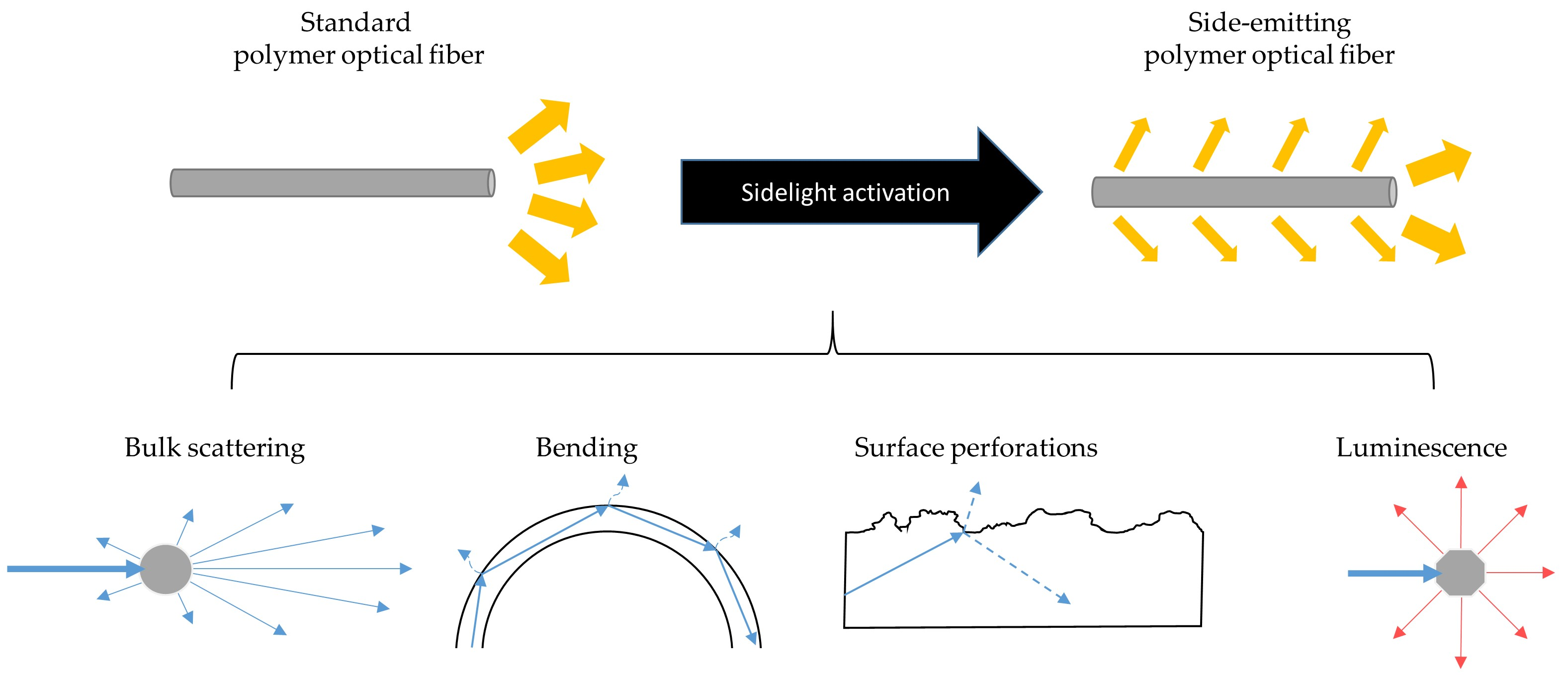
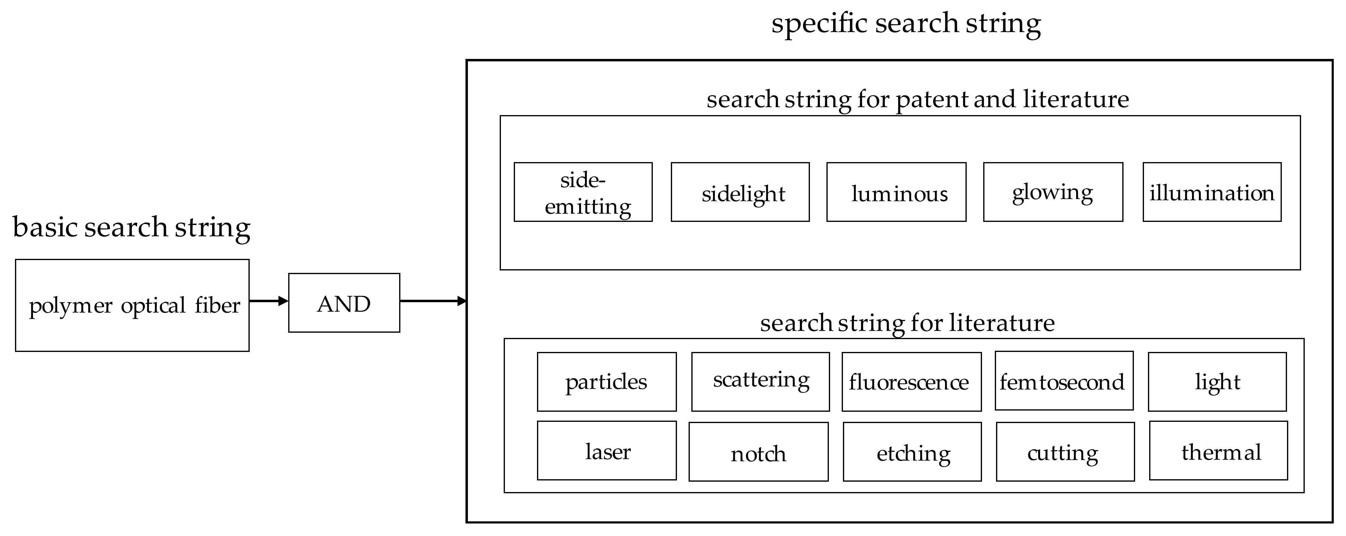
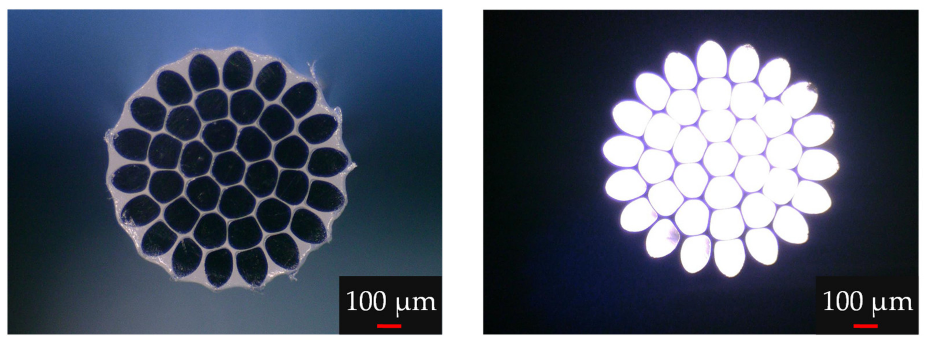
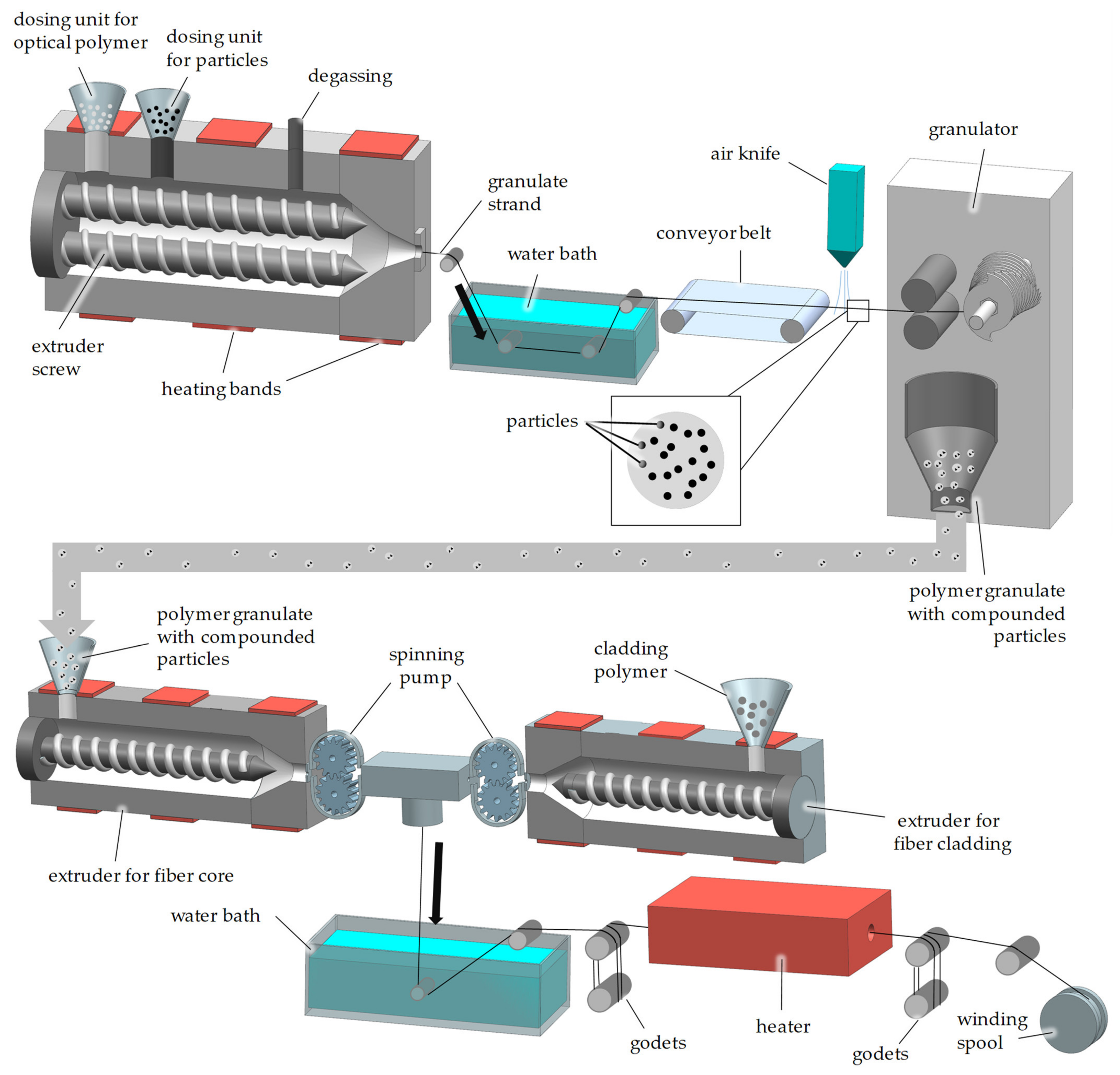
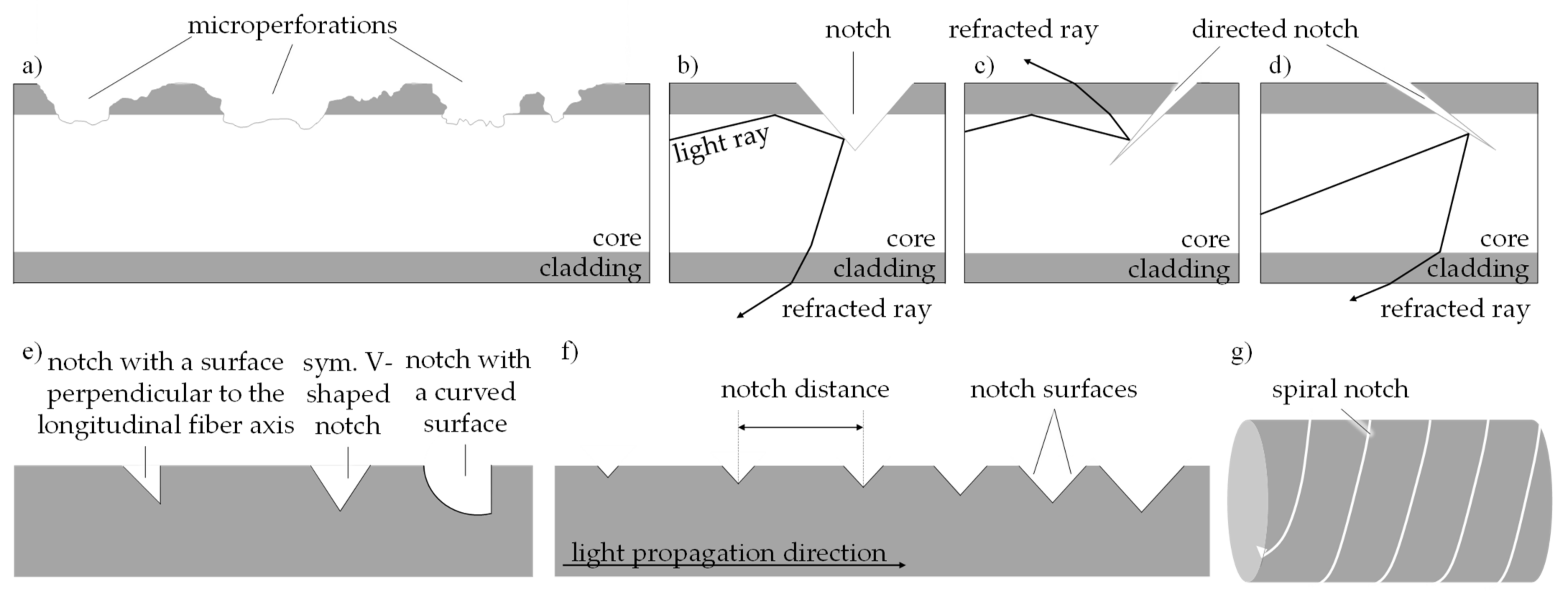
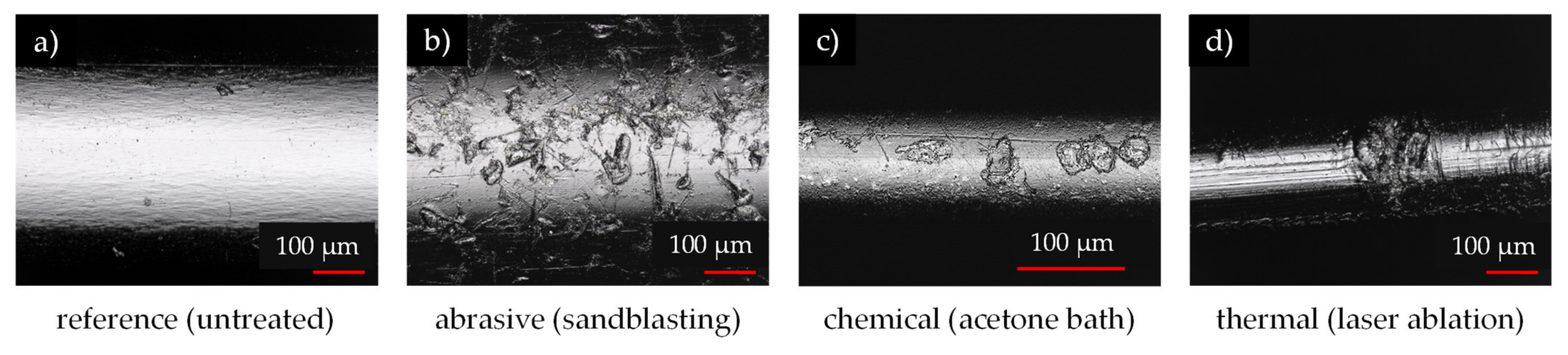
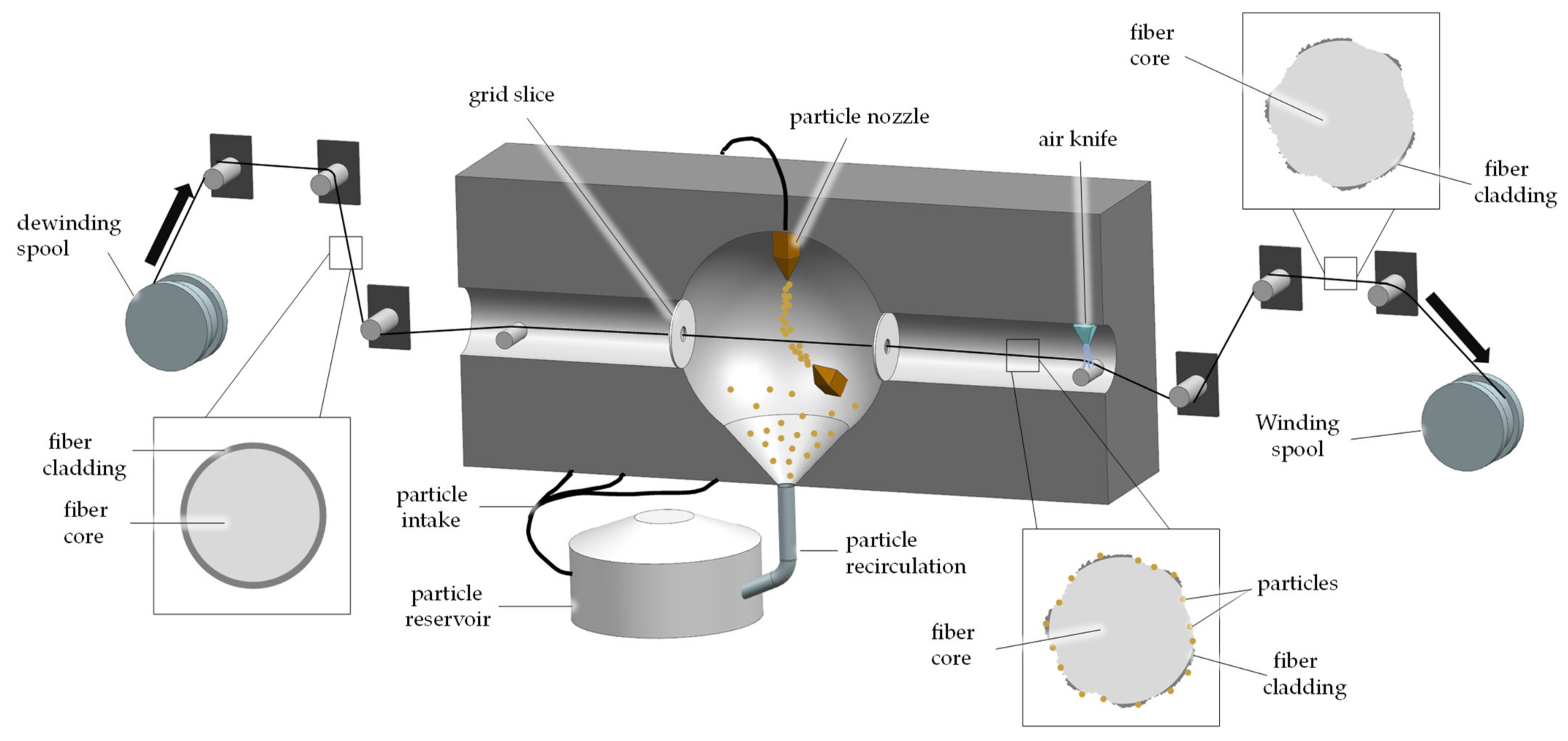
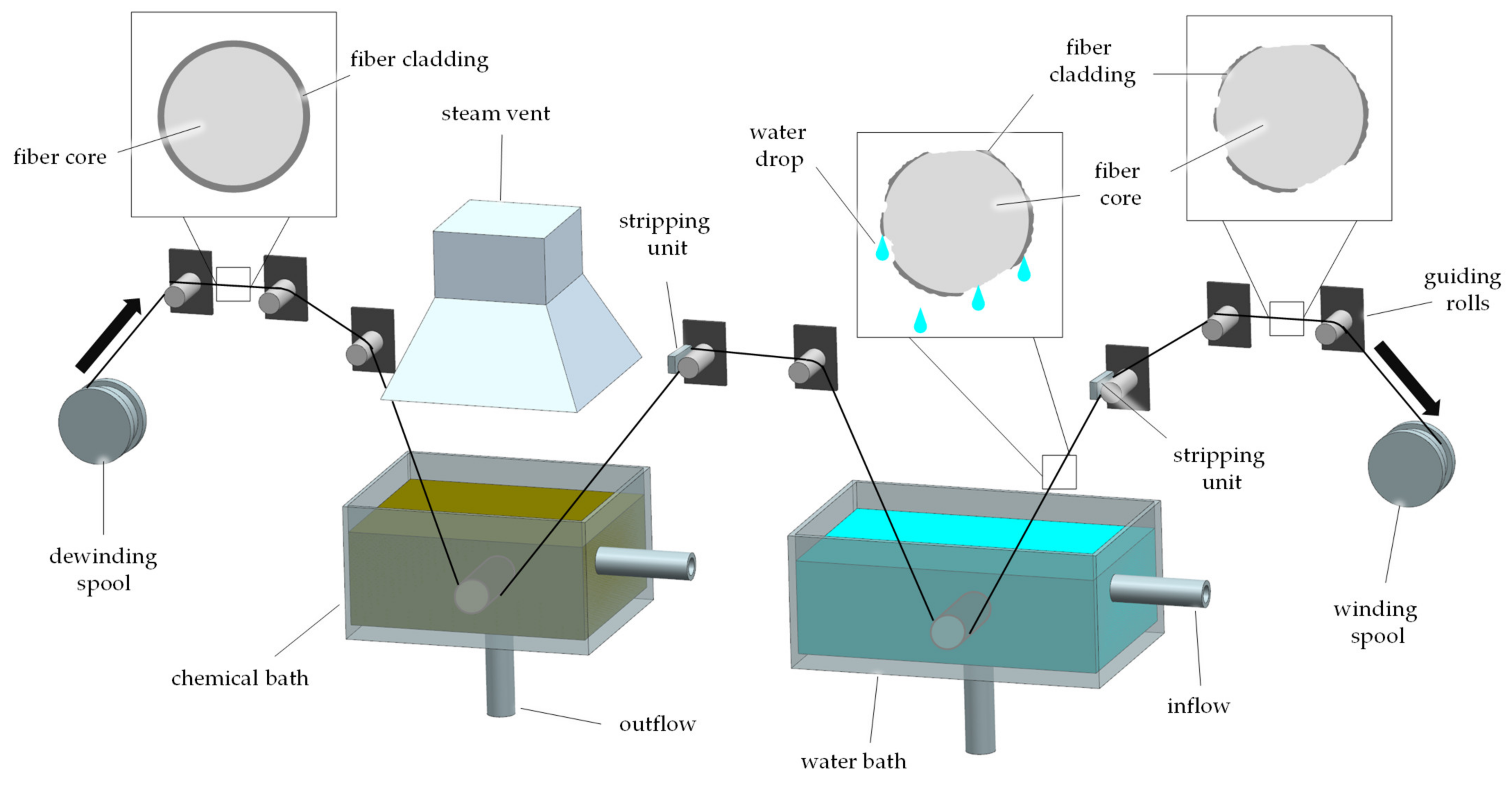
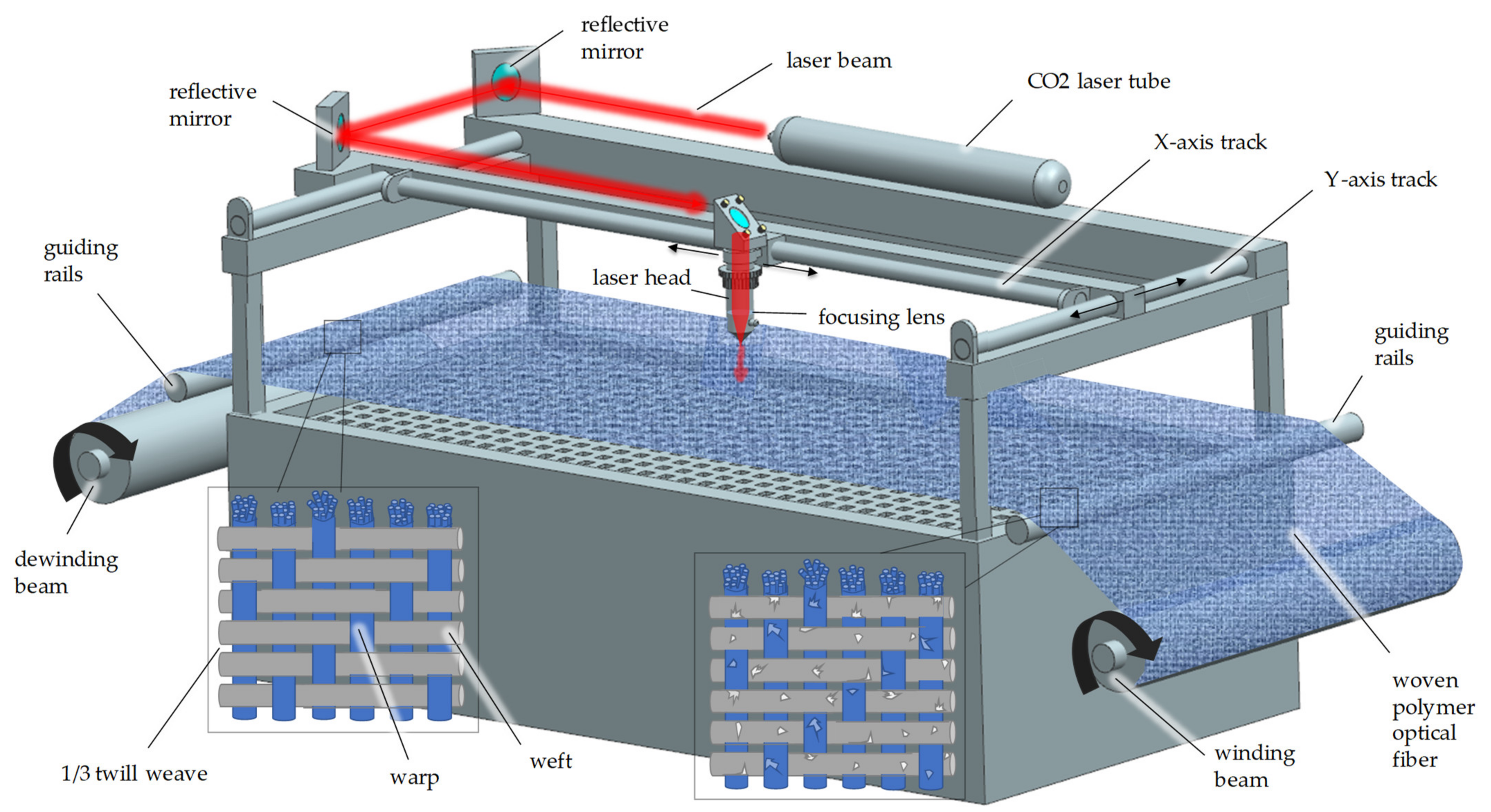
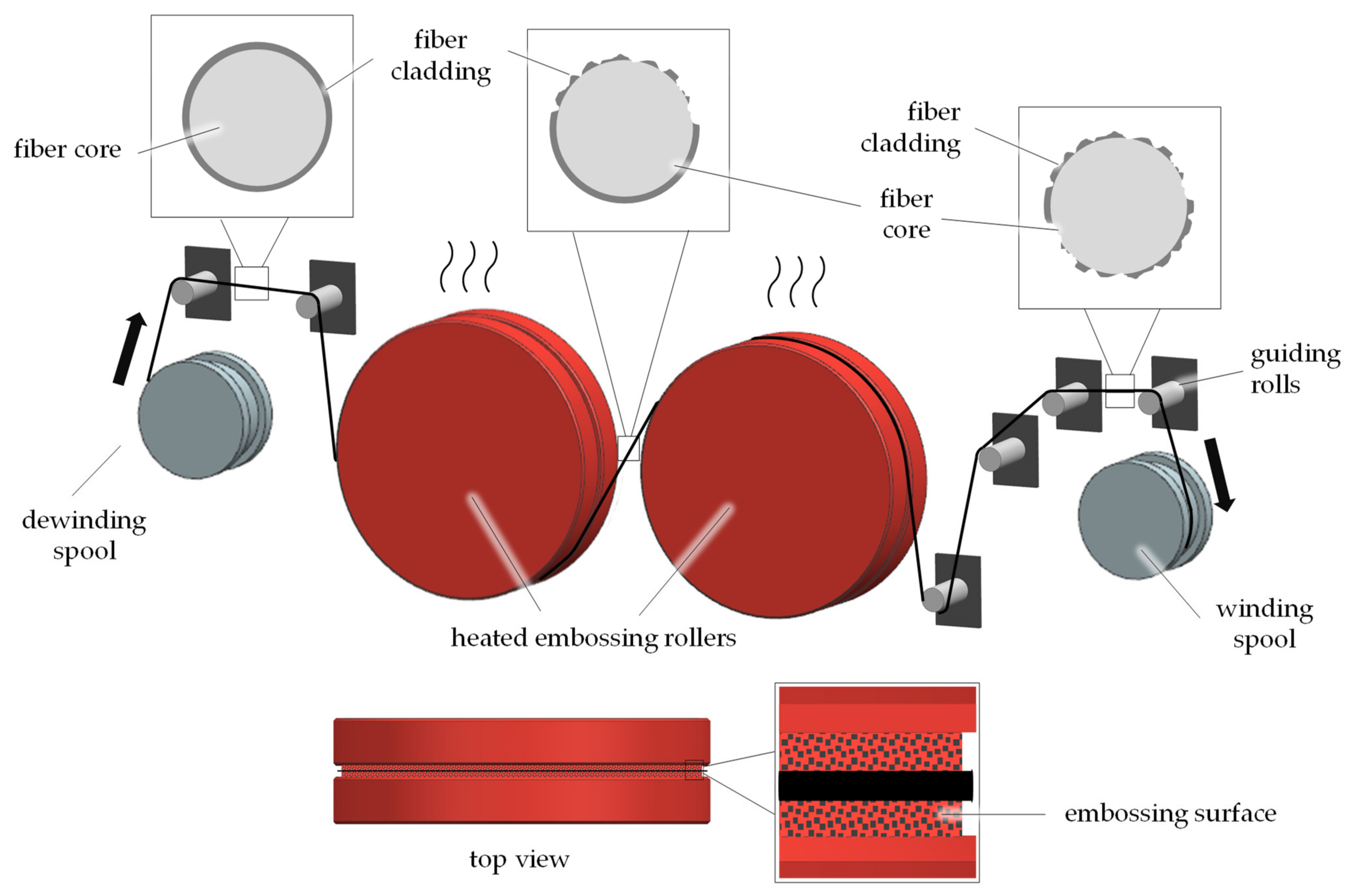
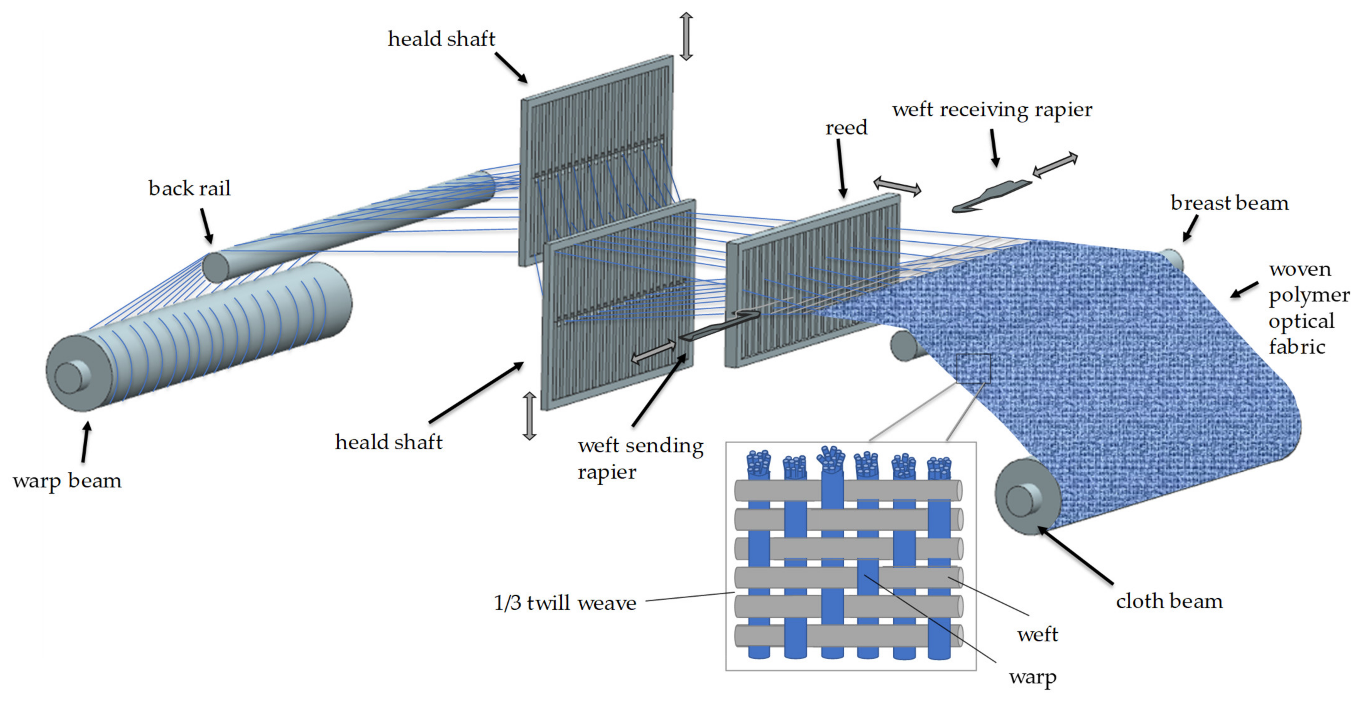
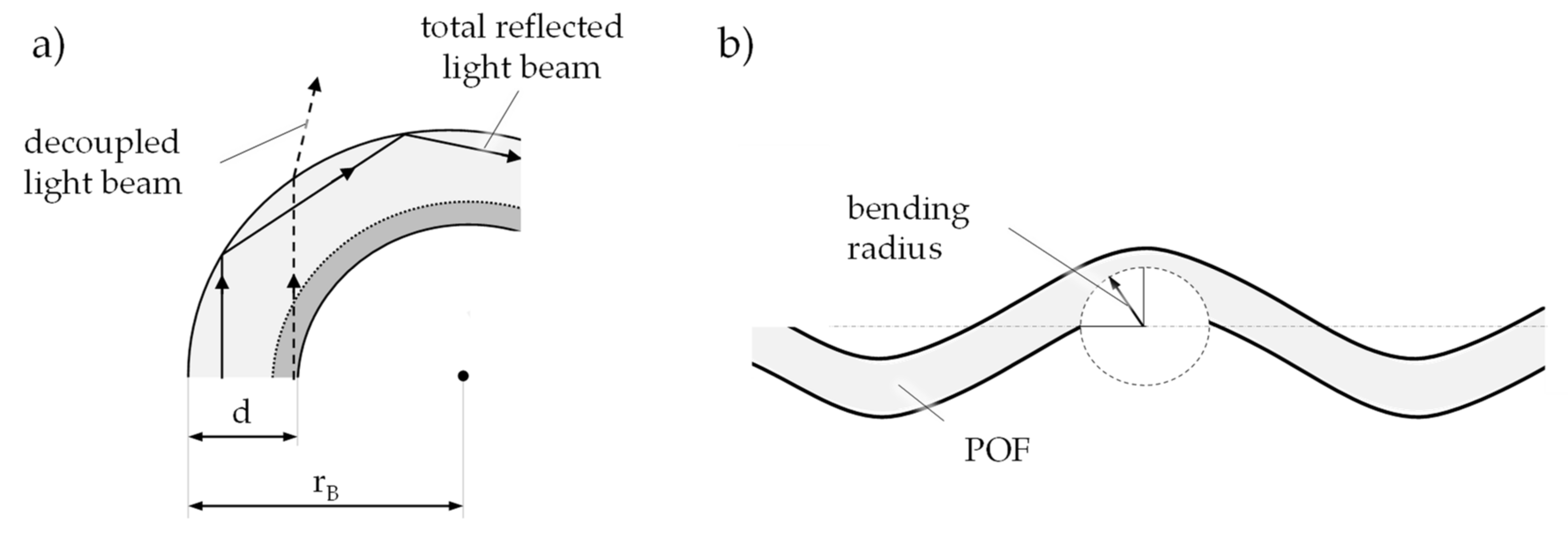
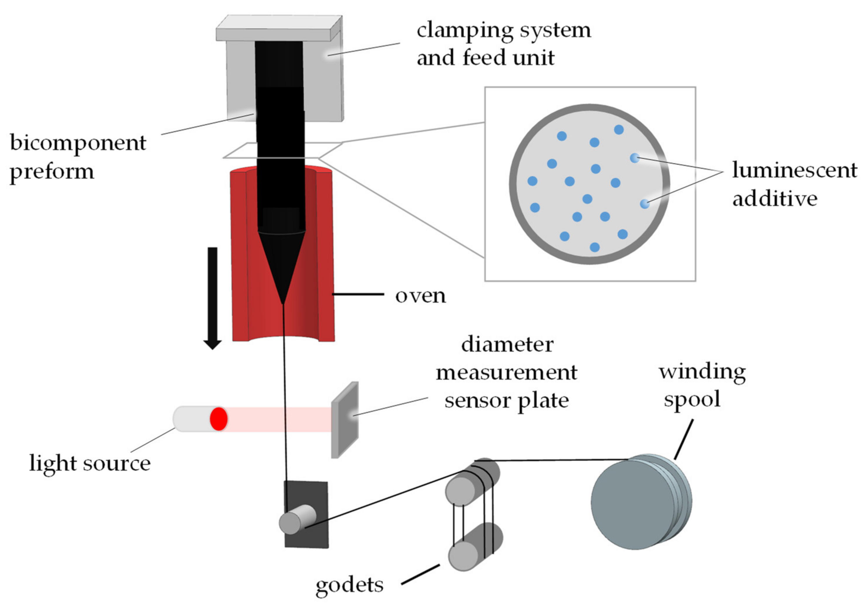
Table 1.
Successive reduction of search results for papers and patents.
| Search results found based on the keywords | 1827 |
| Search results after scanning the titles and the journal names | 419 |
| Search results matching the covered topic | 186 |
| Search results used for this review paper | 106 |
Publisher’s Note: MDPI stays neutral with regard to jurisdictional claims in published maps and institutional affiliations. |
© 2021 by the authors. Licensee MDPI, Basel, Switzerland. This article is an open access article distributed under the terms and conditions of the Creative Commons Attribution (CC BY) license (https://creativecommons.org/licenses/by/4.0/).
Share and Cite
MDPI and ACS Style
Kallweit, J.; Pätzel, M.; Pursche, F.; Jabban, J.; Morobeid, M.; Gries, T. An Overview on Methods for Producing Side-Emitting Polymer Optical Fibers. Textiles 2021, 1, 337-360. https://0-doi-org.brum.beds.ac.uk/10.3390/textiles1020017
AMA Style
Kallweit J, Pätzel M, Pursche F, Jabban J, Morobeid M, Gries T. An Overview on Methods for Producing Side-Emitting Polymer Optical Fibers. Textiles. 2021; 1(2):337-360. https://0-doi-org.brum.beds.ac.uk/10.3390/textiles1020017
Chicago/Turabian StyleKallweit, Jan, Mark Pätzel, Franz Pursche, Junes Jabban, Mohamad Morobeid, and Thomas Gries. 2021. "An Overview on Methods for Producing Side-Emitting Polymer Optical Fibers" Textiles 1, no. 2: 337-360. https://0-doi-org.brum.beds.ac.uk/10.3390/textiles1020017