
Stretchable Textile Yarn Based on UHF RFID Helical Tag


1
Univ Lyon, Université Claude Bernard Lyon 1, INSA Lyon, Ecole Centrale de Lyon, CNRS, Ampère, UMR5005, 69622 Villeurbanne, France
2
Univ Lyon, INSA Lyon, Inria, CITI, EA3720, 69621 Villeurbanne, France
*
Author to whom correspondence should be addressed.
Textiles 2021, 1(3), 547-557; https://doi.org/10.3390/textiles1030029
Submission received: 22 October 2021
/
Revised: 14 November 2021
/
Accepted: 19 November 2021
/
Published: 22 November 2021
(This article belongs to the Special Issue New Research Trends for Textiles)
Abstract
:In the context of wearable technology, several techniques have been used for the fabrication of radio frequency identification (RFID) tags such as 3D printing, inkjet printing, and even embroidery. In contrast to these methods where the tag is attached to the object by using sewing or simple sticking, the E-Thread® technology is a novel assembling method allowing for the integration of the RFID tag into a textile yarn and thus makes it embeddable into the object at the fabrication stage. The current E-Thread® yarn uses a RFID tag in which the antenna is a straight half-wave dipole that makes the solution vulnerable to mechanical strains (i.e., elongation). In this paper, we propose an alternative to the current RFID yarn solution with the use of an antenna having a helical geometry that answers to the mechanical issues and keeps quite similar electrical and radiative properties with respect to the present solution. The RFID helical tag was designed and simulated taking into consideration the constraints of the manufacturing process. The helical RFID tag was then fabricated using the E-Thread® technology and experimental characterization showed that the obtained structure exhibited good performance with of read range in the ultra high frequency (UHF) RFID band and of tolerance in terms of elongation.
1. Introduction
Radio frequency identification (RFID) is a very popular standardized technology that is mainly employed for the identification purposes of objects or people. More precisely, an object associated with a RFID tag is remotely identified by the means of a RFID reader. The communication principle is based on the tag’s load modulation of the backscattered electromagnetic wave [1,2,3], which implies that in most of the cases, the RFID tag is passive (i.e., it uses the transmitted energy from the reader without the need for any additional energy source). RFID is a very interesting concept that contributes to the Internet of Things (IoT) development and, more generally, it is considered as a key technology for humanity [4,5]. The advantages that are offered by RFID tags such as communication without line of sight, low cost, small size, and unique identification have made them an essential candidate for a wide range of applications, for example, logistics, retail, access and identity cards as well as wireless payment systems.
Recently, the emergence of electronic devices that can be worn in, on, or near the body called “wearables” has allowed for the possibility of recovering various physiological information from a human body and transmitting it wirelessly to a processing unit or even to a smartphone [6]. The information obtained from a wearable device can be very useful in a wide range of applications, especially in the health care sector and one of the required operations is the unique identification of the device. For this purpose, in the last years, many efforts have been undertaken in order to develop wearable RFID tags that can be associated with clothing or an accessory in a way that is non-invasive, comfortable, and invisible for the wearer. Popular considerations during the design of wearable RFID tags are usually the impact of deformation on the RFID tag’s performance, the effect of the human body’s proximity to the tag’s electrical and radiative properties or the tag’s washability [7,8,9,10,11]. However, in the encountered studies, the RFID tag’s topology is often kept unchanged from the conventional one (i.e., planar antenna on a substrate with properties that are specific to the application). In fact, the link between a RFID tag and the object it is associated to, is often neglected and the concept of integrating the tag into the object since the manufacturing phase is part of the “Industry 4.0” era.
One of the technologies that supports this idea is E-Thread®, in which the RFID tag’s form factor is reinvented as a RFID textile yarn. The patented technique [12] consists of an automated assembling process during which the RFID chip is associated with a half-wave dipole antenna in a repeated operation. The obtained cascaded RFID tags are then wrapped by a textile material to constitute a spool of textile RFID yarns. When isolated from the spool, one RFID yarn operates in the European Ultra High Frequency (UHF) band and exhibits a reading range of [13]. The current E-Thread® RFID yarn constitutes a very interesting solution as it can be integrated within an object during the fabrication stage and offers great advantages with its slender configuration such as invisibility and comfortable for the user. However, a RFID wearable tag has to be robust to any kind of mechanical constraints such as the elongation, which is lacking in the actual RFID yarn.
In this paper, we propose an alternative solution that consists of using for the tag’s antenna, a helical geometry that has similar mechanical properties to a string. A helical antenna is mainly fabricated by winding a conductive material and its geometrical parameters have an important impact on its electromagnetic properties in terms of input impedance and radiation pattern. Usually, these helical antenna properties are exploited for several scenarios such as phased antenna arrays for millimeter waves and wireless power transfer applications [14,15], wireless sensor nodes in smart agriculture [16] as well as biomedical applications [17,18,19]. However, to the authors’ knowledge, in the literature, very few examples can be found where a helical antenna has been used in a RFID tag. For example, the study in [20] focused on the development of a helical RFID tag to be integrated into a vehicle tire. In this case, the impedance matching between the antenna and the chip was achieved using a transmission line. Meanwhile, in the study presented in [21], a helical antenna was developed for and RFID tag in which the impedance matching was achieved by tuning the geometrical parameters of the antenna.
In a previous work [22], the latter method was employed in order to design a helical antenna for the RFID tag yarn without the use of any additional elements in order to perform the impedance matching. The RFID helical tag exhibited a maximum read range at , which is higher than the frequency of interest and of read range in the European UHF RFID band. As explained, the observed result is due to manufacturing process constraints and one of the given improvement solutions was to design a helical antenna with a spacing between turns that is higher while increasing the antenna’s half-length h.
In this paper, the new UHF RFID helical tag-based textile yarn includes two significant improvements: (i) the helical RFID tag was designed while taking into consideration the manufacturing constraints (the nature of the employed materials and the physical dimensions’ limits), and (ii) the integration of a stretchable core material as a support for the elongation. Compared to the previous version of the helical RFID tag, the suggested methodology design also allows for a manufactured structure to be obtained for which the dimensions and the electromagnetic characteristics are close to the simulated ones. This is possible through a more accurate modeling of the materials’ characteristics in the design process. The rest of this paper is organized as follows. In Section 2, the topology of the helical antenna when integrated into a textile yarn is presented together with the design methodology including electrical and manufacturing specifications. Moreover, criteria for the helical RFID tag characterization using simulation and experiments are given. Section 3 highlights the simulation results in terms of reflection coefficient and radiation pattern. Moreover, the fabricated prototypes as well as the experimental characterization’s results are presented. Finally, conclusions and future work are drawn in Section 4.
2. Materials and Methods
2.1. Topology of the RFID Textile Yarn Integrating a Helical Antenna
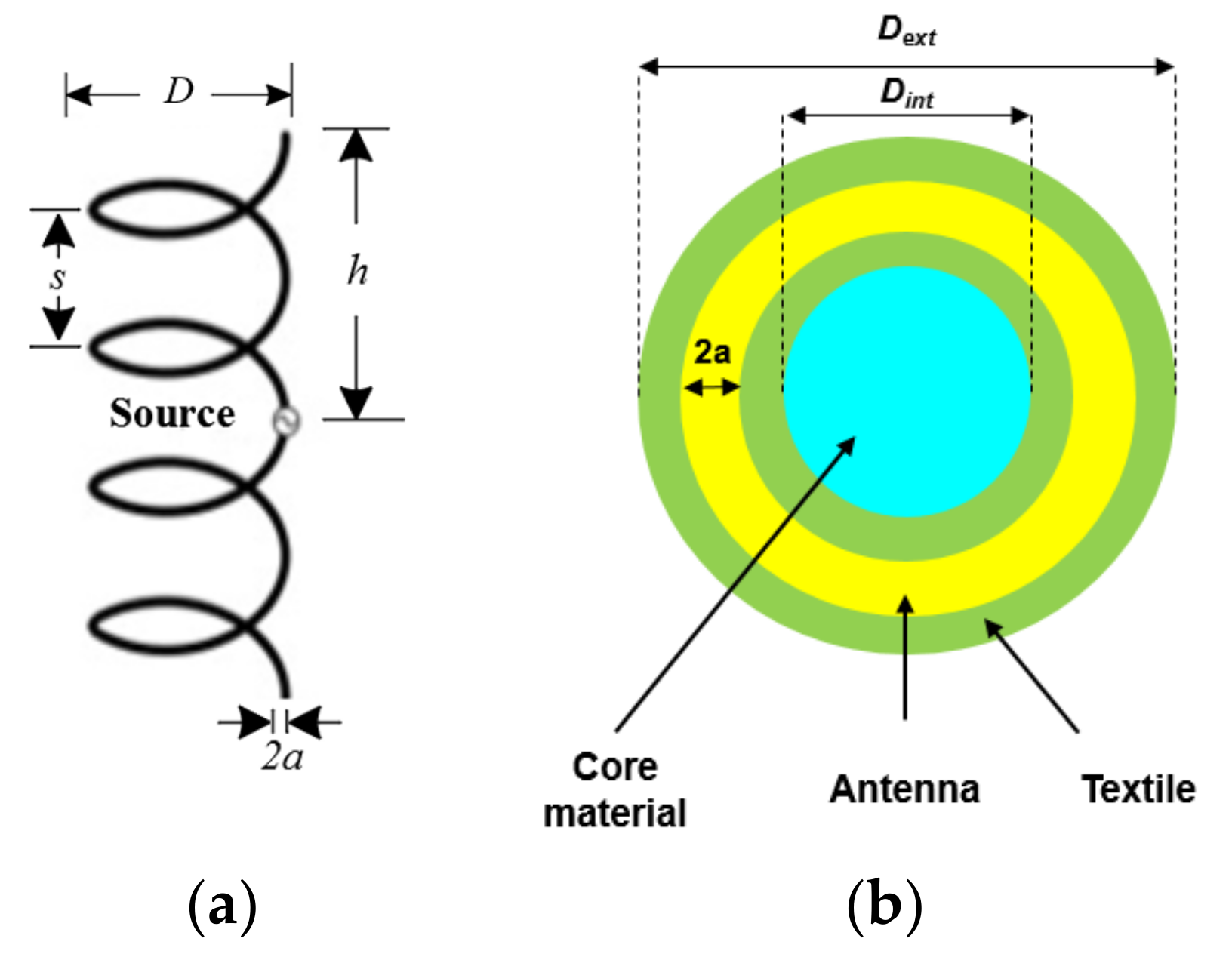
In free space, the helical antenna is characterized by its geometrical parameters, which are the diameter ; the half-length h; the turns number ; the pitch ; and the wire radius , as shown in Figure 1a. As stated, these parameters impact the electromagnetic properties as follows: the diameter and the pitch mainly have an impact on the impedance matching while the half-length h and turns number mainly modify the resonance frequency. Moreover, a helical antenna with a diameter much smaller than the wavelength allows a radiation pattern to be maintained with a normal mode similar to the dipole antenna of the current solution [23].
The RFID helical tags presented in this paper were fabricated using the E-Thread® technology. The E-Thread technology consists of an automated assembling process where a dipole antenna is associated with a RFID chip for which the package was modified beforehand. On the RFID chip edges, two grooves receive two copper wires that form the tag’s antenna [12]. This technique allows for several cascaded RFID tags to be obtained that can have a textile finishing during a wrapping process [13]. Furthermore, in order to obtain the helical shape, an additional step is required. This step consists of wrapping the textile material containing the cascaded RFID tags around a core material giving the helical aspect; here, a stretchable material is employed as the core of the helical antenna offering elongation capabilities. Details on the practical fabrication are given in [22]. Preliminary parametric simulations testing different dielectric constants for the used core material has allowed us to conclude that when the dielectric constant of the core increases, the impedance matching frequency shifts toward the low frequencies. Thus, it is important to identify and characterize the nature of the used material as the core during the antenna design. Indeed, any change after the manufacturing process is very difficult and may strongly deteriorate the RFID yarn.
For the simulation purpose, the textile material used for wrapping and the core material were modeled simply as dielectric materials characterized by their permittivity constant provided by the industrial partner. The dielectric constants for the employed nylon and lycra are and , respectively. A cross section of the helical RFID textile yarn is shown in Figure 1b: is the external diameter of the helical tag integrated in the textile; is the diameter of the cylindrical core material; and is the helical antenna wire’s diameter.
2.2. Design Specifications
In order to design a helical antenna for the RFID textile yarn, electrical specifications have to be guaranteed. In addition to these conditions, manufacturing constraints in terms of dimensioning are imposed by the manufacturing process.
2.2.1. Electrical Specifications
- The helical RFID tag has to operate, here (but without loss of generality on the concept), within the European UHF RFID band ; and
- The considered RFID integrated circuit (IC) is the Monza R6 [24] and its impedance is at . This RFID IC is used by the industrial partner for the current commercialized solution. However, the design methodology is independent from the IC choice.
2.2.2. Manufacturing Constraints
In order for the RFID helical tag design to be compatible with the E-Thread® manufacturing process, some of the helical antenna’s geometrical parameters have to respect certain limitations (which for the most part are therefore fixed according to manufacturing constraints):
- The helical antenna’s pitch has to be higher than . As explained in [22], the value of this parameter depends on the rotation speed of the conductive filament around the core material. Consequently, the value that meets the manufacturing process and employed for our design methodology was ;
- The core material around which the copper conductive wire was wound had a diameter of . A lower diameter strongly alters the impedance matching while a high value leads to a complex winding process. Consequently, this condition allows us to make a compromise between the manufacturing process and the helical RFID tag’s performance;
- The external diameter , which depends on the textile material thickness, is provided by the industrial partner as ; and
- The conductive wire diameter was fixed to and corresponded to the copper’s diameter used in the E-Thread® process.
Hence, the geometrical parameters of the helical antenna that can be varied in order to design a helical RFID tag while meeting the specifications are: the half-length h and the turns number . Table 1 summarizes the variable and the fixed geometrical parameters.
2.3. Helical Antenna’s Simulated Structure
All the presented simulations were performed using CST Microwave Studio 2018, electromagnetic simulation commercial software.
The described helical RFID tag was configured in 3D and a full view is shown in Figure 2a. In addition, a vertical cross section is illustrated in Figure 2b. The pitch and the diameter that strongly impact the impedance matching of the helical antenna have been fixed for manufacturing constraints and thus, only the resonance frequency can be modified. For this purpose, the number of turns and the half-height h are simultaneously varied in order to obtain a resonance frequency in the UHF RFID band.
2.4. Characterization of the Helical RFID Tag
Here, the designed helical RFID tag was characterized in two ways. First, by simulation, and more precisely by evaluating its impedance matching and its radiation pattern. Second, the tag was evaluated by experimental tests through the measurements of the read range and by estimating its robustness to stretching.
2.4.1. Helical RFID Tag’s Impedance Matching
Unlike other RF scenarios in which the antenna’s impedance has to be matched to , in RFID, the antenna’s impedance has to be matched with the IC’s impedance. The impedance matching is evaluated through the complex power wave reflection coefficient , which can be expressed as in Equation (1):
where is the helical antenna’s input impedance.
2.4.2. Helical RFID Tag’s Read Range
In most applicative contexts of UHF RFID, the read range is a very important criterion to describe the performance. In order to compare the experimental result to the one obtained by simulation, the read range can be calculated using the theoretical expression obtained from the Friis transmission equation:
where is the wavelength; is the power transmitted by the reader; is the reader’s antenna gain; is the tag’s antenna gain; is the polarization loss; is the tag’s activation threshold that represents the power needed for the IC to start operating; and is the power transmission coefficient defined as:
It is worth noting that the quantity represents the equivalent isotropic radiated power (EIRP). Its maximum value depends on the geographical location, for instance, the value imposed by the European Telecommunications Standards Institute (ETSI) is , whereas the tag’s activation threshold is specific to the chosen IC.
In the presented work, the Voyantic Tagformance commercial test bench [25] was used to measure the read range.
2.4.3. Helical RFID Tag’s Robustness in Terms of Stretching
In order to measure the helical RFID tag’s tolerance to elongation, the Voyantic Bench test was also used after performing some modifications in order to correspond to our application. More precisely, both the antenna extremities are attached to a basic textile filament that is wound around two spools. As shown in Figure 3, the spools’ rotation, clockwise and counter clockwise, allows for the application of an elongation on the tag. The read range is then measured for each considered elongation.
3. Discussion of the Simulation and Measurement Results
3.1. Helical RFID Tag’s Reflection Coefficient and Its Radiation Pattern
After optimization, the helical RFID tag’s geometrical parameters were: h = 50 mm; , in addition to the fixed ones given in Table 1. The reflection coefficient obtained from simulation is shown in Figure 4. It can be observed that the tag’s antenna exhibited a minimum value of the reflection coefficient of at .
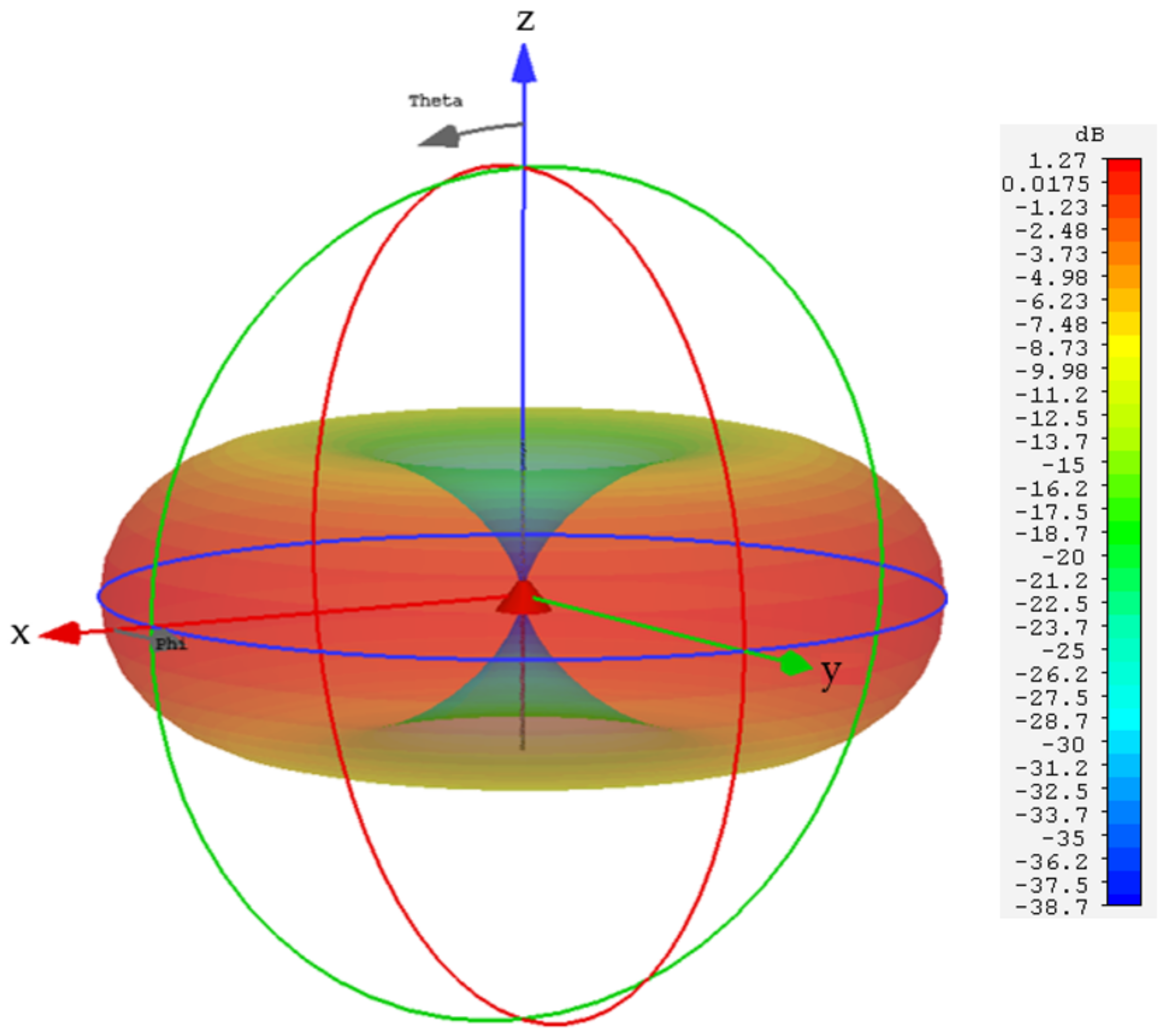
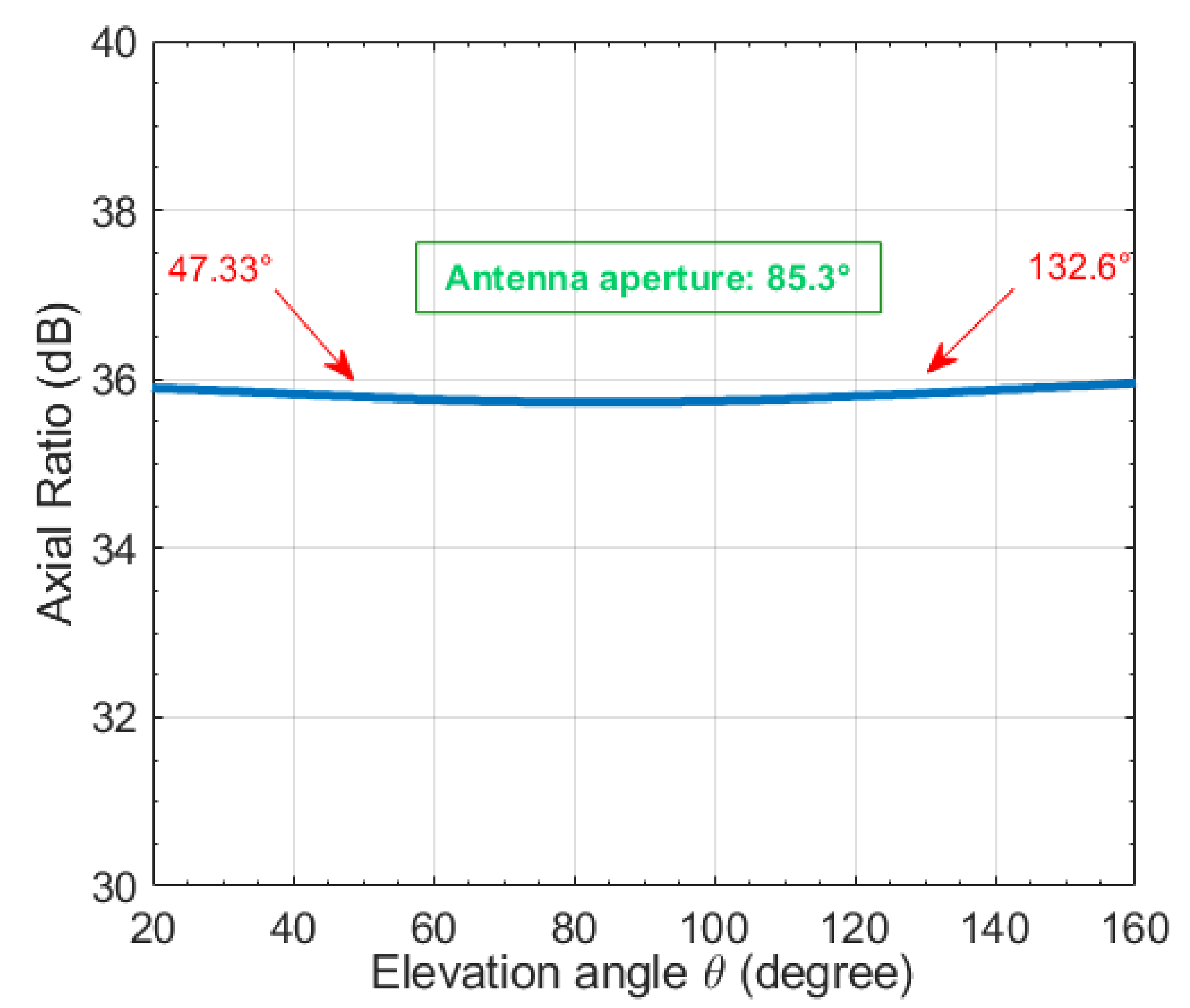
The radiation pattern obtained by simulation is shown in Figure 5, where the antenna is positioned along the z-axis and has a maximum gain of . It can be seen that the radiation pattern was omnidirectional in the xoy plan, which is identical to a half-wave’s dipole radiation pattern. Moreover, through the obtained axial ratio (AR) as shown in (Figure 6), defined as for the main lobe ( and being the orthogonal components of the radiated electric field), the antenna is elliptically polarized with a vertical major axis [23].
3.2. Helical RFID Tag’s Experimental Characterization
3.2.1. Fabricated Prototypes
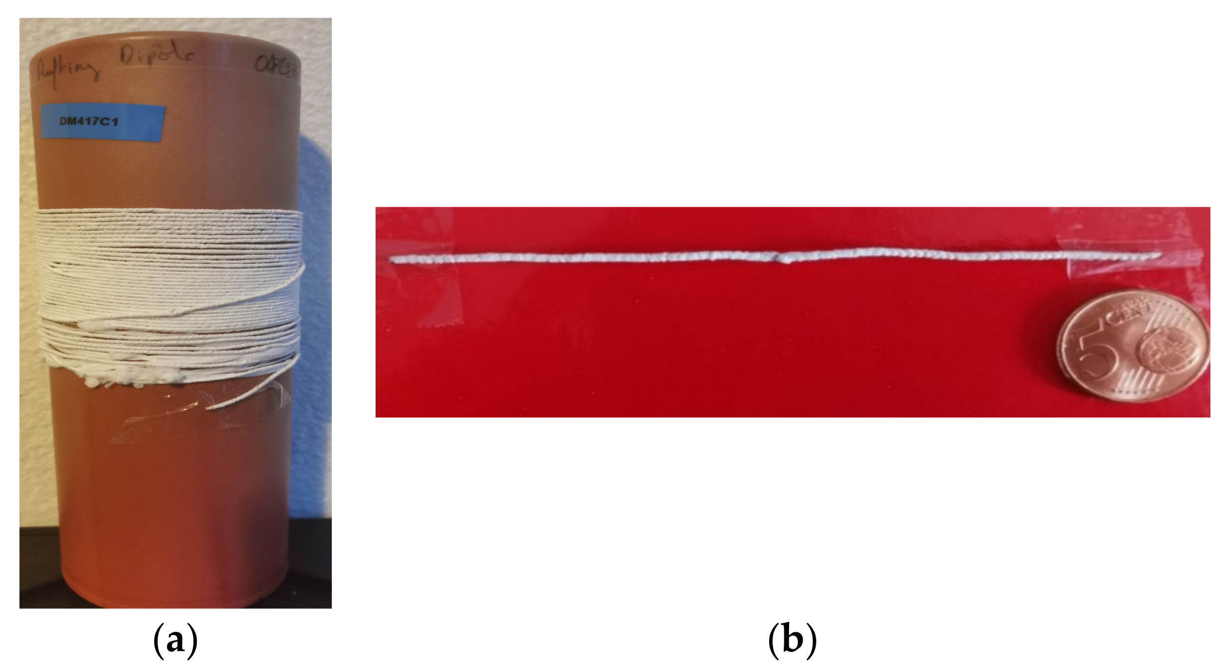
Figure 7a presents the fabricated textile yarn obtained from the modified E-Thread® assembling process. The spool of the textile filament is composed of helical RFID tags, which are cascaded. Note that in practice, each tag can be cut at the appropriate length in order to be operational at the desired frequency. One helical RFID tag was isolated from the spool by cutting at the length that allowed it to have a resonance frequency in the UHF RFID band.
The obtained RFID helical tag is shown is Figure 7b and has the following geometrical parameters: h = 47.5 mm; in addition to the ones given in Table 1. An error of can be observed regarding the height, which is due to the fact that in the simulation, the material properties are known with a certain imprecision and the pitch s is not ideal. Thus, the helical tag’s length has to be adjusted after fabrication.
3.2.2. Measured Read Range of the Helical RFID Tag
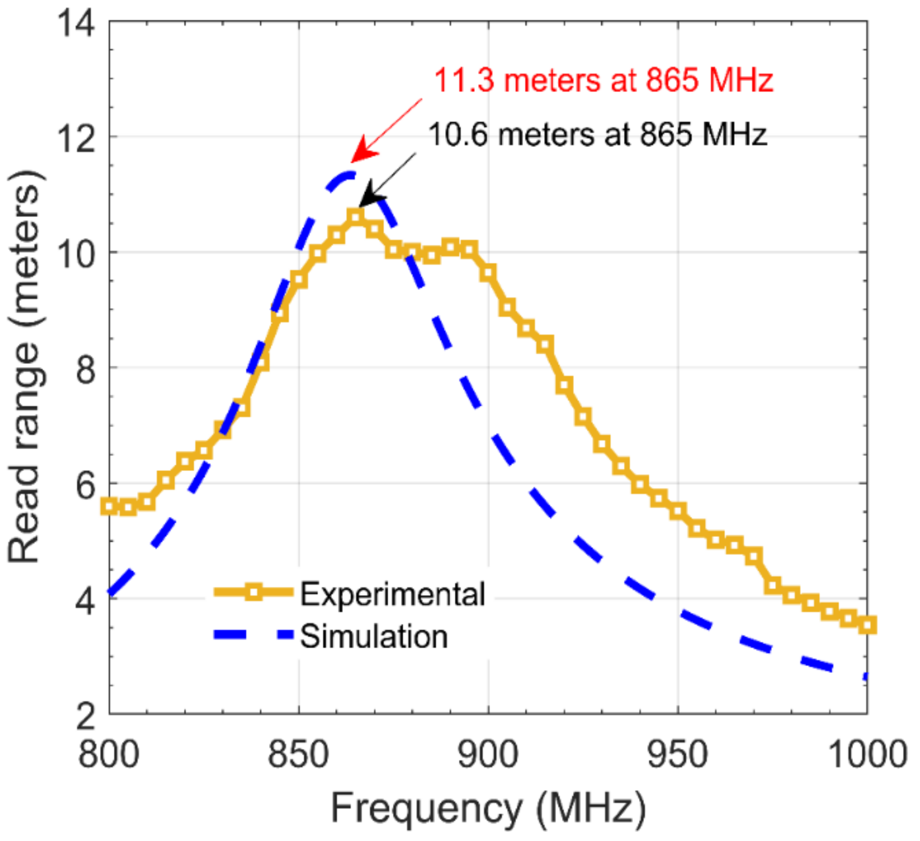
Considering that the RFID reader has an EIRP of and the IC has a threshold power , the measured read range and the one deduced from the simulation using Equation (2) are shown in Figure 8. It was shown that the helical RFID tag exhibited a maximum measured read range of at the frequency of . Moreover, the RFID helical tag exhibited a wide band behavior as it can be operational in the U.S. UHF RFID band with a read range of . The measured result is coherent with respect to the simulation as the maximum read range obtained by the simulation was at . It is also worth remarking that the gain value of the antenna helped to compensate for the transmission coefficient and allowed a read range to be obtained closer to that of the current E-Thread solution ().
Moreover, it can be remarked that compared to the simulation, a wider frequency bandwidth was obtained in the experiment, which is very advantageous for an applicative scenario. The difference in the results may be explained by the manufacturing process (some inaccuracies in the dimensions and the permittivity values of materials), which does not allow for an exact fit with the dimensions employed in the simulation.
3.3. Evaluation of the Helical RFID Tag’s Robustness in Terms of Stretching
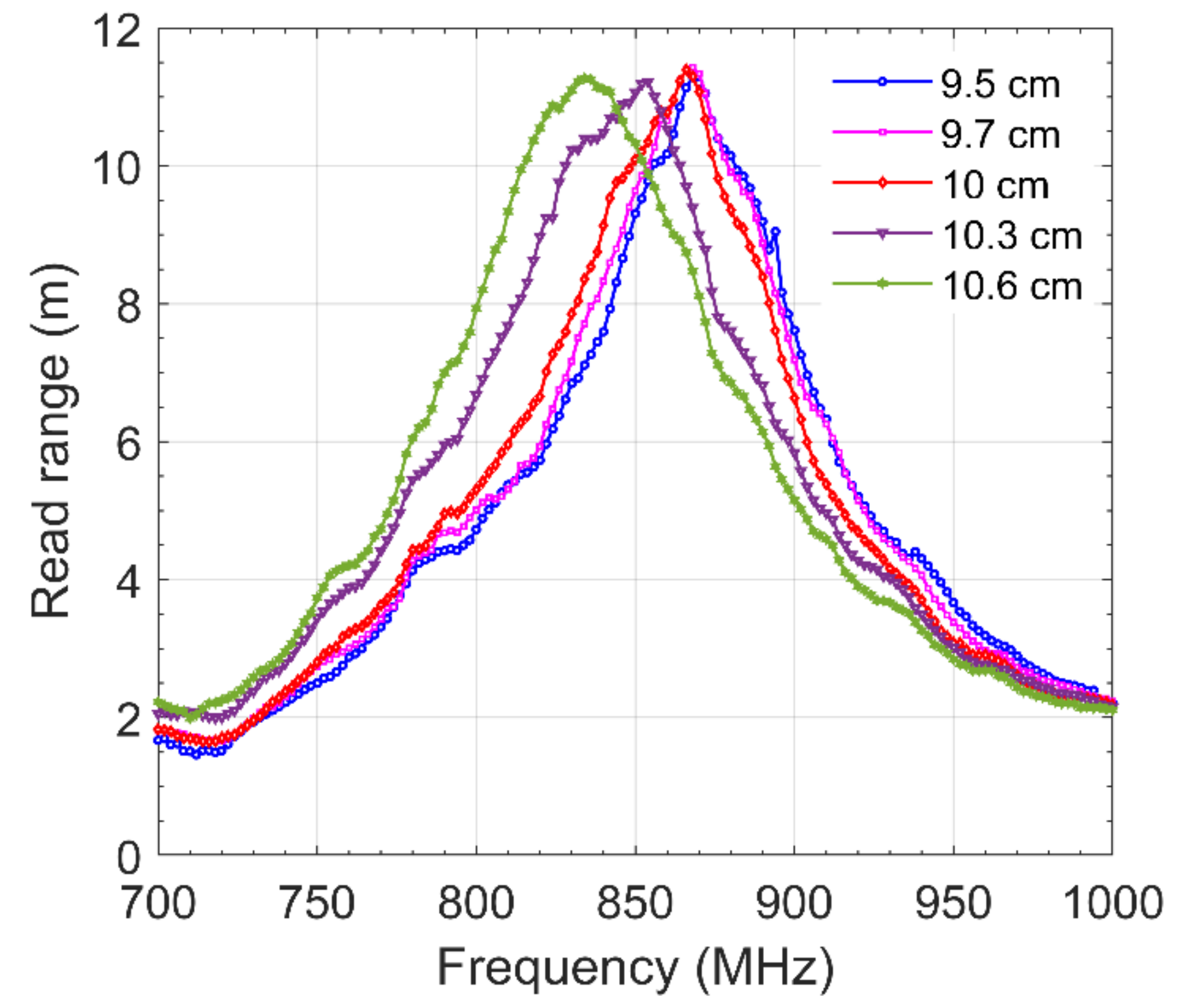
The impact of the tag’s elongation on the read range was measured and the results are presented in Figure 9. At the initial state (without elongation) for an antenna having the total length of , the maximum read range was at which is higher than the previously shown result. This small difference may be attributed to the fact that in the previous measurement, the antenna was slightly bent; this also shows the impact that the curvature will have for a tag in wire form. It can also be observed that up to a length of , the helical RFID tag’s read range is maintained at the frequency of interest. However, beyond this length, the resonance frequency is shifted to lower frequencies, which is coherent with the increase in the length of an antenna. At the maximum considered length of , the tag was still readable at a range of (18% of loss) at the frequency of interest.
From these measurements, the robustness of the proposed antenna was confirmed in terms of the read range performance as well as the structural aspect of the textile material.
4. Conclusions
In this paper, a helical RFID tag was designed to be integrated into a textile yarn using the E-Thread® technology. The simulation results showed that fixing the parameters such as the pitch s and the diameter D made a complex impedance matching process due to the strong impact these parameters have on the helical antenna input impedance. However, the tag’s read range maybe improved to reach a value close to the one obtained in the current solution by ensuring an antenna gain that enables compensating the reflection coefficient . Another improvement solution might be adding lumped elements to achieve an impedance matching with the inconvenience of a complex manufacturing process. From the experimental measurements, the helical RFID tag exhibited a read range of 10.6 m, which is an improvement considering the previous work [15]. Compared to the current solution of the RFID yarn using a half-wave dipole that has a read range of 12 m, the helical RFID tag offers a close read range with the advantage of being robust to elongation. Indeed, as the experiments have demonstrated, up to an elongation of 10% from the initial length, the helical RFID tag is still readable at 9 m.
The presented helical RFID tag may be used in a wide range of applications. The capabilities of the helical RFID tag could also be expanded beyond the classical identification purposes to some other functionalities, for example, using the antenna elasticity in order to measure strain deformation and thus the textile helical RFID tag becomes a sensor.
Author Contributions
Conceptualization, S.B.; methodology, S.B., F.D.H. and Y.D.; software, S.B.; validation, S.B., F.D.H. and Y.D.; formal analysis, S.B.; investigation, S.B., F.D.H. and Y.D.; writing—original draft preparation, S.B.; writing—review and editing, F.D.H. and Y.D.; supervision, F.D.H. and Y.D.; funding acquisition, Y.D. All authors have read and agreed to the published version of the manuscript.
Funding
This research was funded by the “La Région Auvergne Rhône-Alpes” Lyon, France, through the “Pack Ambition Recherche 2017” program.
Data Availability Statement
Not applicable.
Acknowledgments
The authors would like to thank the company Primo1D for their help during the manufacturing process and the experimental characterization.
Conflicts of Interest
The authors declare no conflict of interest.
References
- Nikitin, P.V.; Rao, K.V.S. Antennas and Propagation in UHF RFID Systems. In Proceedings of the IEEE International Conference on RFID, Las Vegas, NV, USA, 16–17 April 2008; pp. 277–288. [Google Scholar]
- Keehr, E.A.; Lasser, G. Making a low-cost software-defined UHF RFID reader. IEEE Microw. Mag. 2021, 22, 25–45. [Google Scholar] [CrossRef]
- Athauda, T.; Karmakar, N. Chipped versus chipless RF identification: A comprehensive review. IEEE Microw. Mag. 2019, 20, 47–57. [Google Scholar] [CrossRef]
- Duroc, Y.; Tedjini, S. RFID: A key technology for humanity. Comptes Rendus Phys. 2018, 19, 64–71. [Google Scholar] [CrossRef]
- Zannas, K.; Matbouly, H.E.; Duroc, Y.; Tedjini, S. From identification to sensing. In Wireless Power Transmission for Sustainable Electronics; Wiley: Hoboken, NJ, USA, 2020. [Google Scholar]
- Fernández-Caramés, T.M.; Fraga-Lamas, P. Towards the internet of smart clothing: A review on IoT wearables and garments for creating intelligent connected E-Textiles. Electronics 2018, 7, 405. [Google Scholar] [CrossRef] [Green Version]
- Bakkali, M.E.; Martinez-Estrada, M.; Fernandez-Garcia, R.; Gil, O.; Mrabet, E. Effect of Bending on a Textile UHF-RFID Tag Antenna. In Proceedings of the 14th European Conference on Antennas and Propagation, Copenhagen, Denmark, 15–20 March 2020. [Google Scholar]
- Koski, K.; Lohan, E.S.; Sydanheimo, L.; Ukkonen, L.; Rahmat-Samii, Y. Electro-Textile UHF RFID Patch Antennas for Positioning and Localization Applications. In Proceedings of the IEEE RFID Technology and Applications Conference (RFID-TA), Tampere, Finland, 8–9 September 2014; pp. 246–250. [Google Scholar]
- Björninen, T.; Virkki, J.; Sydanheimo, L.; Ukkonen, L. Impact of Recurrent Washing on the Performance of Electro-Textile UHF RFID tags. In Proceedings of the IEEE RFID Technology and Applications Conference (RFID-TA), Tampere, Finland, 8–9 September 2014; pp. 251–255. [Google Scholar]
- Corchia, L.; Monti, G.; Tarricone, L. Wearable antennas: Nontextile versus fully textile solutions. IEEE Antennas Propag. Mag. 2019, 61, 71–83. [Google Scholar] [CrossRef]
- Kiourti, A. RFID antennas for body-area applications: From wearables to implants. IEEE Antennas Propag. Mag. 2018, 60, 14–25. [Google Scholar] [CrossRef]
- Vicard, D.; Brun, J. Cap for a Chip Device Having a Groove, Device Provided with Said Cap, Assembly Consisting of the Device and a Wire Element, and Manufacturing METHOD thereof. U.S. Patent App. 14,428,254, 13 August 2015. [Google Scholar]
- Andia, G. Slenderly and Conformable Passive UHF RFID Yarn. In Proceedings of the IEEE International Conference on RFID, Phoenix, AZ, USA, 9–11 May 2017; pp. 130–136. [Google Scholar]
- Song, Z.; Li, Y.; Zheng, H.; Li, Y.; Li, E. Design of an Electronically Steerable Dielectric Helical Antenna Phased Array for Millimeter Wave Applications. In Proceedings of the Global Symposium on Millimeter-Waves & Terahertz (GSMM), Nanjing, China, 23–26 May 2021; pp. 1–3. [Google Scholar]
- Mardani, H.; Buchanan, N.; Fusco, V.; Naeem, U. Increasing the Wireless Power Transfer (WPT) Link Efficiency by High Gain Helices. In Proceedings of the IEEE Texas Symposium on Wireless and Microwave Circuits and Systems (WMCS), Waco, TX, USA, 18–20 May 2021; pp. 1–4. [Google Scholar]
- Okada, N.; Koshimizu, S.; Shimasaki, H. Helical Antennas in 920-MHz Band for Wireless Sensor Nodes under the Ground. In Proceedings of the International Symposium on Antennas and Propagation (ISAP), Osaka, Japan, 25–28 January 2021; pp. 325–326. [Google Scholar]
- Mizuno, H.; Takahashi, M.; Saito, K.; Ito, K. Design of a Helical Folded Dipole Antenna for Biomedical Implants. In Proceedings of the 5th European Conference on Antennas and Propagation (EUCAP), Rome, Italy, 11–15 April 2011; pp. 3484–3487. [Google Scholar]
- Karnaushenko, D.D.; Karnaushenko, D.; Makarov, D.; Schmidt, O.G. Compact helical antenna for smart implant applications. NPG Asia Mater. 2015, 7, e188. [Google Scholar] [CrossRef] [Green Version]
- Binti Mohd Baharin, R.H.; Yamada, Y.; Kamardin, K.; Michishita, N. Changes of Electric Current on a Normal-Mode Helical Antenna Inside a Human Body. In Proceedings of the IEEE Conference on Antenna Measurements & Applications (CAMA), Tsukuba, Japan, 4–6 December 2017; pp. 403–406. [Google Scholar]
- Yamada, Y.; Hong, W.G.; Jung, W.H.; Michishita, N. High Gain Design of a Very Small Normal Mode Helical Antenna for RFID Tags. In Proceedings of the TENCON IEEE Region 10 Conference, Taipei, Taiwan, 30 October–2 November 2007; pp. 1–4. [Google Scholar]
- Liao, Y.; Zhang, K.; Cai, K.; Liang, Z. Impedance Matching Design of Small Normal Mode Helical Antennas for RFID Tags. In Proceedings of the International Symposium on Antennas and Propagation, Nanjing, China, 23–25 October 2013; pp. 1150–1153. [Google Scholar]
- Benouakta, S.; Hutu, F.; Sette, D.; Duroc, Y. UHF RFID elastic textile yarn. Microw. Opt. Technol. Lett. 2020, 62, 3186–3194. [Google Scholar] [CrossRef]
- Kraus, J.D. The helical antenna. Proc. IRE 1949, 37, 263–272. [Google Scholar] [CrossRef]
- Impinj. Monza 6 Product Brief. Available online: https://support.impinj.com/hc/en-us/articles/202765328-Monza-R6-Product-Brief-Datasheet (accessed on 15 March 2021).
- Voyantic. Tagformance Pro. Available online: https://voyantic.com/products/tagformance-pro (accessed on 2 January 2021).
Figure 1.
(a) Helical antenna configuration; (b) Cross section of the RFID textile yarn integrating the helical antenna.
Figure 1.
(a) Helical antenna configuration; (b) Cross section of the RFID textile yarn integrating the helical antenna.

Figure 2.
Helical antenna in 3D. (a) Full view of the structure. (b) Vertical cross section of the structure.
Figure 2.
Helical antenna in 3D. (a) Full view of the structure. (b) Vertical cross section of the structure.
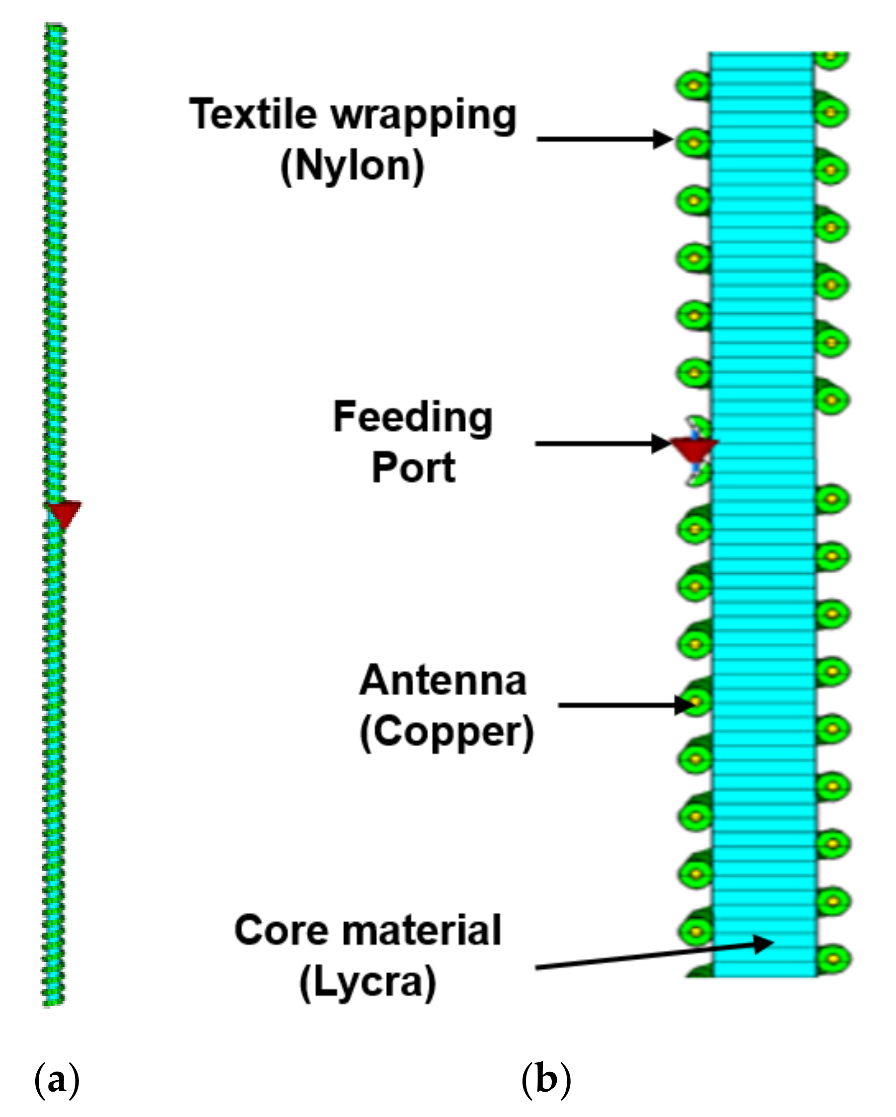
Figure 3.
Modified Voyantic test bench for the measurement of the helical RFID tag’s reading range when elongation efforts are applied.
Figure 3.
Modified Voyantic test bench for the measurement of the helical RFID tag’s reading range when elongation efforts are applied.
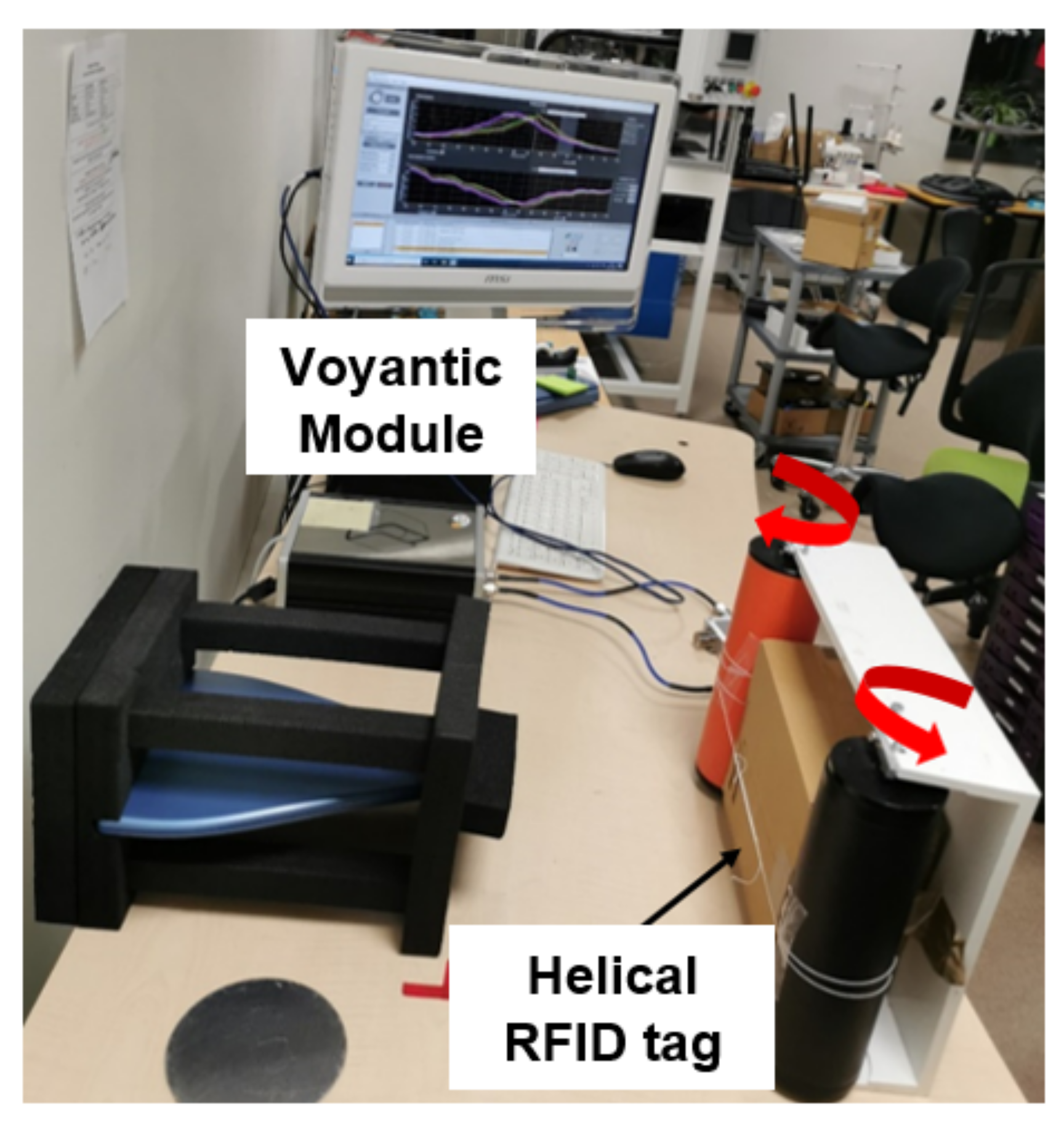
Figure 4.
Reflection coefficient obtained by simulation at the antenna feed point.
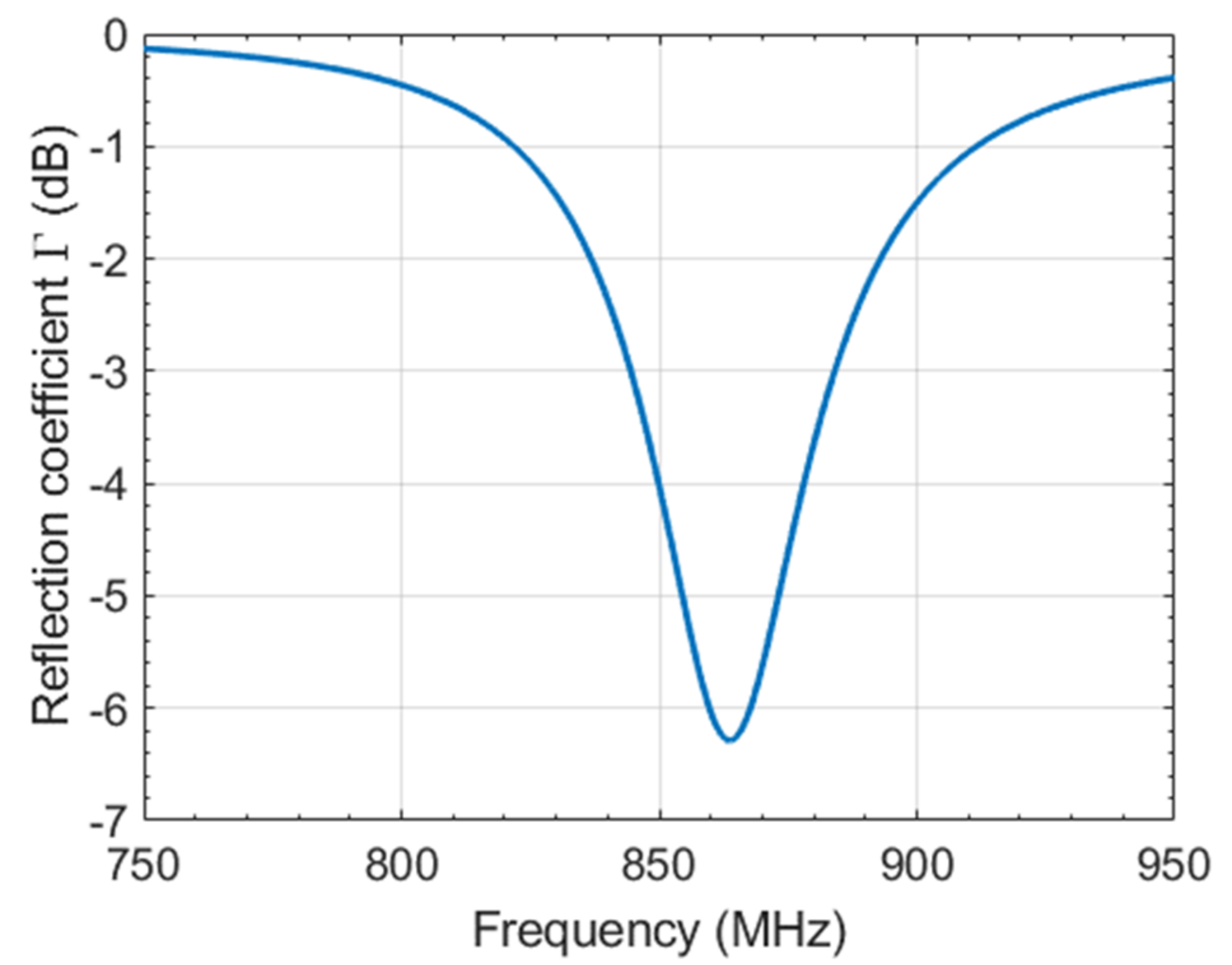
Figure 5.
Helical RFID antenna’s radiation pattern.

Figure 6.
Helical antenna’s axial ratio for an azimuth angle . The axial ratio is independent of the azimuth angle.
Figure 6.
Helical antenna’s axial ratio for an azimuth angle . The axial ratio is independent of the azimuth angle.

Figure 7.
Fabricated helical RFID tags. (a) Spool of cascaded helical RFID tags. (b) RFID helical tag after isolation from the spool.
Figure 7.
Fabricated helical RFID tags. (a) Spool of cascaded helical RFID tags. (b) RFID helical tag after isolation from the spool.

Figure 8.
Helical RFID tag’s read range obtained by simulation and by experimental measurement.

Figure 9.
Impact of the stretching on the helical RFID tag’s read range, obtained by experimental measurements.
Figure 9.
Impact of the stretching on the helical RFID tag’s read range, obtained by experimental measurements.

Table 1.
Geometrical parameters of the helical antenna integrated into a textile yarn.
| Geometrical Parameters | Value [mm] |
|---|---|
| Dext | |
| Dint | |
| s | |
| a | |
| h | Varied |
| N | Varied |
Publisher’s Note: MDPI stays neutral with regard to jurisdictional claims in published maps and institutional affiliations. |
© 2021 by the authors. Licensee MDPI, Basel, Switzerland. This article is an open access article distributed under the terms and conditions of the Creative Commons Attribution (CC BY) license (https://creativecommons.org/licenses/by/4.0/).
Share and Cite
MDPI and ACS Style
Benouakta, S.; Hutu, F.D.; Duroc, Y. Stretchable Textile Yarn Based on UHF RFID Helical Tag. Textiles 2021, 1, 547-557. https://0-doi-org.brum.beds.ac.uk/10.3390/textiles1030029
AMA Style
Benouakta S, Hutu FD, Duroc Y. Stretchable Textile Yarn Based on UHF RFID Helical Tag. Textiles. 2021; 1(3):547-557. https://0-doi-org.brum.beds.ac.uk/10.3390/textiles1030029
Chicago/Turabian StyleBenouakta, Sofia, Florin Doru Hutu, and Yvan Duroc. 2021. "Stretchable Textile Yarn Based on UHF RFID Helical Tag" Textiles 1, no. 3: 547-557. https://0-doi-org.brum.beds.ac.uk/10.3390/textiles1030029