
Image Assisted Total Stations for Structural Health Monitoring—A Review


i3mainz, Institute for Spatial Information and Surveying Technology, Mainz University of Applied Sciences, Lucy-Hillebrand-Straße 2, D-55128 Mainz, Germany
Geomatics 2022, 2(1), 1-16; https://0-doi-org.brum.beds.ac.uk/10.3390/geomatics2010001
Submission received: 19 November 2021
/
Revised: 13 December 2021
/
Accepted: 21 December 2021
/
Published: 23 December 2021
Abstract
:Measuring structures and its documentation is one of the tasks of engineering geodesy. Structural health monitoring (SHM) is defined as a periodic or continuous method to provide information about the condition of the construction through the determination of measurement data and their analysis. In SHM, wide varieties of sensors are used for data acquisition. In the following, the focus is on the application of image assisted total stations (IATS). The combination of tacheometry and photogrammetric measurement offers high flexibility and precision. Different approaches of automated detecting and matching whose applications have been tested in practice are briefly explained. A distinction is made between built-in cameras (commercial) and external camera systems (prototypes). Various successful applications of IATS in the field of SHM are presented and explained.
1. Introduction
Structural health monitoring (SHM) deals with the systematic measurement of structures and their characteristics, such as factory chimneys, bridges, wind turbines or dams. These are periodically examined in order to gain possible conclusions about the structural health of the object [1,2].
Due to environmental impacts and permanent strain, civil structures in particular are affected by damaging influences such as cracking in the concrete, spalling, corrosion of the steel and even failure of the structure. For the years 2017 to 2020, the German government provided EUR 2.9 billion in budgetary funds for the repair and renovation of bridge structures [3]. In addition to the economic costs, safety concerns are coming into focus. As the Ponte Morandi motorway bridge [4] in Italy or the Florida International University pedestrian bridge [5] in the United States have shown, there is an enormous risk for users or pedestrians if structures fail or partially fail. SHM is an efficient and reliable method to monitor the condition of structures and is necessary to detect damage to structures. The most common method is visual inspection, carried out by experienced inspectors. Often this is very time-consuming and leads to traffic obstructions or temporary closure of the structure.
Another approach is the concept of the “smart bridge”. Already during the construction phase, bridges are equipped with adaptive sensors to enable a complete evaluation of the bridge. First existing bridges are comprehensively evaluated and then expanded appropriately with sensor technology [6].
The instruments commonly used include accelerometers [1,7], extensometers [8,9], terrestrial laser scanners (TLS) [10,11] or tachymeters [12,13]. Of particular interest are measurements to determine the vibration and displacement behaviour of the structures. It is possible to analyse the monitored vibrations and calculate the natural frequencies. Changes in this natural frequency indicate possible structural damages and require further investigation by qualified experts. It is also possible to compare the parameters determined by the measured values with the calculation from a finite element model (FEM) [14,15]. By this way, measured values can be compared with calculated values and analysed.
Another complementary measuring system to the SHM is the use of camera sensors, e.g., in form of so-called image assisted total station (IATS). IATS are characterised by the extension of a total station by using one or more cameras. The accuracy of the angle measurements of the total station is combined with photogrammetry and the associated simple target mark definition. By using telescope lenses, the distance to the structure is increased; depending on the situation, the danger zone does not have to be entered. Signalling on the object can be omitted due to the photogrammetric evaluation. However, this depends on the specific monitoring object. If there is not enough texture or contrast on the structure, signalisation may be necessary. Numerous examples of applications with IATS and signalling can be found in the literature [14,16,17,18,19].
Deformations are evaluated by capturing image information from a camera and natural frequencies can be calculated. Without continuous distance measurements, a two-dimensional movement parallel to the camera sensor can be measured. The measurement field is limited by the field of view (FoV). For the measurement of frequencies, the maximum frames per second (fps) are essential. Only by an adequately frequent sampling rate the natural frequency can be determined from the measured values.
In this review, we introduce the IATS (Section 3), classified into commercial instruments and research prototypes (with external cameras). The focus will be on the IATS extending the total station with an external camera to substitute the camera integrated by the manufacturer. We will present the image processing methods used to determine targets in Section 3.3. Following this, various field tests of SHM with IATS on structures and the resulting outcome will be presented (Section 4). Finally, the results are discussed, and the practicability of the system is evaluated.
2. Materials and Methods
The current systematic review follows the Preferred Reporting Items for Systematic Reviews and Meta-Analysis (PRISMA) [20,21]. The research performed in June 2021 to find the relevant papers was conducted by browsing “Image Assisted Total Station*” AND “Structural Health Monitoring” and “Video tachymetry” AND “Structural Health Monitoring” on Google Scholar and EBESCO Discovery Service, defining the period from 2000 to 2021. The first step excludes the duplicates and all papers that are not in English or German. The next step involves the assessing of the collected papers based on irrelevant abstracts or content. The research resulted in identifying 39 relevant papers. The papers were classified into three topics: camera-only system, built-in and external camera system for total stations. Camera-only systems are not discussed in the following because of the lack of a total station and therefore these seven papers were also excluded.
Fifteen additional papers were found by reviewing citations of the remaining 32 relevant papers whereby 10 of these were classified as suitable. This results in the total number of 42 relevant papers.
The following Figure 1 presents the processing steps trough the different phases of finding relevant papers for this systematic review.
3. Image Assisted Total Station (IATS)
Since the beginning of 2000, the development of IATS has continued. For many manufacturers, the integration of one or more cameras into a total station has become standard. The integration of cameras enables to record the relevant scene and offers additional potential for the evaluation by the image-based recording. The combination of angular measurement accuracy from tacheometry in conjunction with image processing of captured image data has expanded the applicability also in the field of SHM. At IATS’s, a camera is installed in the line of sight and the visual filed is captured by the image. Limitations are the FoV of the camera used and the need for light (at least for the observed object). The automatic acquisition of images removes the need for human aiming and thus the potential impact of error. A major advantage is that there is no need for access to the structures, as prominent points on the structure can be observed directly without the use of reflectors. Measurement points can be flexibly selected over the entire structure, if a clear view of it is accessible. The focus here is on the mobile use of IATS. Due to the advantage of non-contact measurement, this measurement method can also be used spontaneously.
Using image-processing techniques such as template matching or feature matching, distinctive points can be extracted and their movement detected [22,23]. Various algorithms have been tested for their practical suitability and are explained in more detail in this paper.
To achieve the desired accuracy, a calibration of the different sensors is necessary. For fixed commercial systems, the calibration parameters are provided by the manufacturer. Some of these calibrations are carried out under the aspect of using the display, e.g., to rotate the instrument, and does not represent a complete photogrammetric calibration. For modular systems or external cameras, the parameters have to be determined in advance. By using a calibration, the captured images are directly georeferenced and measurements in the images become possible.
A basic distinction is made between commercial total stations, where the manufacturer integrates the camera as a sensor, and research prototypes, where an external camera is attached to the total station instead of the ocular. Advantages and disadvantages are explained and discussed.
An overview of the entire historical development of photo and video theodolites up to today’s IATS is described in [14].
3.1. Commercially Available Systems
The technical development up to today’s state of the art reaches into the last century. Based on the technical development of tacheometers, these were successively expanded by further software, sensors and technology up to today’s IATS. According to [14], total stations can be divided into 4 different types (total station, robotic total station, image-assisted total station and image-assisted scanning total station) based on the integrated sensors and functions. Accordingly, IATS includes data registration, electrical distance measurement (EDM), reflectorless EDM, motorization, image sensor, automated aiming, tracking and imaging. By adding a scanning function, the term image-assisted scanning total station (IASTS) becomes applicable.
Today’s instruments usually have the possibility to store additional information of the measured points by the captured images and videos. Images are digitally linked to surveyed points and stored externally for documentation purposes via memory card or interface. The collected georeferenced image data are available for photogrammetrical evaluation. The development of autofocusing and motorisation of the instruments allows for a point of interest to be selected in the image (with the help of the display) and the instrument aligns automatically. This way of data acquisition optimises the previous measurement process. In the event that the instrument is equipped with a scan function, the scan area can be defined in the display using the image-based selection option.
Various manufacturers of IATS have established their products on the market; in the following, some instruments are briefly introduced.
By integrating two VGA cameras into a total station, Topcon created a new generation of IATS in 2005 [14]. A wide-angle camera with fixed focus (FoV 28° × 22°), was mounted next to the telescope enabling it to rotate accordingly. The second coaxial camera (FoV 1°30’ × 1°30’) records the image section through the telescope with variable focus. In 2019, Topcon launched the GTL-1000, an instrument that fits under the IASTS designation, equipped with a full dome laser scanner integrated into a robotic total station. According to the manufacturer, a 5 megapixel CMOS sensor is installed [24] but there is no definition for the possible framerate because GTL only allows capturing a single image. The GTL-1000 has no function to provide images continuously.
The Leica Nova TS60, Leica offers an IATS for permanent or campaign monitoring for bridges, buildings and steel structures [25]. The motorised IATS has two integrated cameras. The overview camera with a FoV of 19.4° and a telescope camera with 1.5°. It is equipped with a 5 megapixel CMOS sensor with a resolution of 2560 × 1920 pixels. The achievable frame rate is up to 20 frames per second.
With the Trimble S9/S9 HP, Trimble labelled a total station for monitoring applications in 2015. The integrated camera (not available in all models) has a FoV of 16.5° × 12.3° with a resolution of 2048 × 1536 pixels. The sensor specification is only a colour digital image sensor [26]. The instrument has a simple scan mode. The Trimble SX 12 [27], which was introduced at the beginning of 2021, includes an overview and a primary camera, which are both positioned parallel to the measurement axis, a telescope camera with coaxial position and a plummet camera for stationing. The cameras integrated in the telescope are already calibrated. The resolution of the chips is 3296 × 2472 pixels. With the telescope camera, one pixel corresponds to 0.69 mm at a distance of 50m. The Trimble SX 12 has no eyepiece hence controlling and aiming is done via the field computer. Since this instrument already has advanced scanning functions it can be classified as an IASTS similar to the Topcon GTL-1000.
3.2. Research Prototypes
In the development of prototypes, different types of construction have emerged since the year 2000. On the one hand, there are external implementations making it possible to mount the camera on the ocular or to replace it. These are used in combination with commercial total stations or tacheometers, and can be converted and adapted to the monitoring conditions. The technical development of the automated focus in the total station made the enormously simplified combination of external cameras possible. Examples of such a modular system would be DAEDALUS [16,17,30,31] of ETH Zurich, MoDiTa [32,33,34] of i3mainz or the applications of the University of Zagreb [14,35] using a GoPro5.
In 2010, [16] presented DAEDALUS, a measurement system originally for automatic online astro-geodatic observations, and also for the use in SHM. The setup includes replacing the eyepiece with a CCD chip. Since no further optical components are installed, the image is no longer displayed exactly in the plane of the crosshair instead the image is now displayed in the plane of the CCD chip. This can be compensated for distances up to 13 m by changing the focus position. For longer distances, an additional lens is required on the telescope. The camera used is a monochrome Guppy F-080C from Allied Vision Technologies (AVT). The CCD sensor has a resolution of 1024 × 768 pixels with a pixel size of 4.65 µm and a frame rate of 30 Hz (full frame) up to 60 Hz (reduced field of view) [31]. At that point in time, no automated focusing was available for tacheometers. Therefore, for the necessary focusing, a special mechanism was developed enabling to autofocus by means of a small stepper motor without modification of the total station. When using newer generations of total stations or multistations with coaxial cameras already installed, the focus mechanism is already available and the special mechanics for focusing is no longer needed. The compatibility is given for models of the TCA, TPS, TS and MS series from the manufacturer Leica [17]. For applications with required software pulses, control by means of a GNSS receiver can be implemented for precise control of exposure start and exposure time. The optical system has a resolution of approximately four arcseconds/pixel (1.1 mgon/pixel).
The prototype MoDiTa developed by i3mainz (University of Applied Sciences Mainz) is based on modularity. Via bayonet ring the camera replaces the standard eyepiece of the tacheometer. The camera used is mounted on the eyepiece using an adapter. By this way the crosshair plane is also captured. There are no changes at the optical beam path in the telescope. This allows a quick exchange of the camera or a quick change to the classical application of the total station. Based on the modular design both, camera and total station, are replaceable. Attached to the telescope is a counterweight to compensate for the weight of the camera. Due to the modular design of the external cameras, active crosshair tracking is required during the measurement. Because of longer pauses between measurements or after changing the telescope position, the crosshair position may change. In [32], a motorised theodolite TM5100 and TM5100A from Leica is extended by means of a CCD camera and used for collimation and autocollimation measurements. As an example, in [33] a monochromatic CMOS sensor camera from the manufacturer IDS with a resolution of 1280 × 1024 pixels is used for the measuring. The camera achieves a frame rate of 60 Hz for full images, up to 2200 Hz for image sections and up to 62500 lines per second in single line mode. Similar to [16], a precise time signal can be produced using a GNSS receiver. The camera and the total station are controlled via own software development and GeoCom or USB ports. The necessary calibration can be carried out in situ and is described in more detail in [34].
Another prototype was presented in 2017 by combining a Leica TPS1201 and a GoPro5 Hero camera [35]. This camera offers different video recording modes. It is possible to choose between different FoV (narrow, linear, medium, wide and superview), resolutions (720 × 400, 1280 × 720, 1920 × 1080, 2560 × 1440, 2704 × 1520, 3840 × 2160 pixel) and recording speeds (30–240 Hz). The field of view and the recording mode are directly related. An adapter is required for the camera mounting on the TPS1201. This was manufactured in a 3D printing process and offers the possibility to attach the camera to the eyepiece of the telescope. According to [14], there is no vertical movement of the mounted camera on the telescope after stability tests in the laboratory. The instrument is controlled via interfaces through a laptop. The camera is managed by a smartphone application. For the evaluation of the video sequences, the video has to be converted into images. These images are orthogonally projected using the known azimuth and zenith angles from the total station and converted from an RGB image to a binary black and white image. After these processing steps, the pixel coordinates of the searched target can be calculated by means of image processing.
The second design offers the advantage of a fixed camera with the instrument. This provides constant calibration parameters as opposed to the modular version which requires calibration after reconfiguration. An early prototype is mentioned 2004 in [36] and the prototype series IATS2 from the manufacturer Leica in [18,29,37,38,39,40]. Based on the knowledge gained from [36], a small series of instruments was produced in 2007, based on the TCRA1200 series. The eyepiece and crosshair were replaced by a CMOS colour chip with a resolution of 2560 × 1920 pixels at 2.2 µm pixel size. One pixel on the image sensor corresponds to an angular value of 0.61 mgon. In [39] a possible frame rate of 5 to 200 Hz is specified, depending on the measuring mode. By connecting the focusing ring to a servomotor, automated focusing is possible. Camera and total station are addressed via GeoCom or USB interfaces. Since this prototype no longer has a crosshair, this must be specified in the image for the necessary calibration. In [38], the chip centre is defined as reference point and the calibration is carried out according to the principle of the virtual control point field. A detailed description of the calibration can be found in [36,37]. The measurement accuracy of a target detection that can be achieved shows sub-pixel accurate determinations with an angular accuracy of >0.6 mgon under laboratory conditions and thus corresponds to the usual accuracy of such algorithms.
In Table 1 the different prototypes are compared with their main specifications and characteristics described in the papers mentioned.
3.3. Automatic Detection and Matching
The great advantage of using an IATS is that even non-signalized points can be monitored, provided they are distinctive enough. Due to changing light conditions and atmospheric impacts, automation is not trivial.
It is important that the observed point can be clearly identified within the captured images. By calibrating the camera and the total station, the pixel coordinates can be transformed into directions. By additional distance measurements, with a previously calculated orientation, 3D coordinates of a global reference system of the observed point may also be calculated. Alone by the high number of images, which are seized with a vibration observation for example, an automatic detection and retrieval of the prominent point is essential.
In photogrammetry, numerous methods have been developed for these tasks. As with all optical methods, the existing light conditions play an important role. The accuracy that can be achieved depends on various aspects such as object size, resolution and correct focusing [39]. Since deformation measurements are to be performed repeatedly, methods detecting discrete single points are of particular interest, but there are also area-based approaches.
According to [36,42] three main categories of matching are classified. Feature based matching extracts distinctive features in images by an operator in the first step and detects these features again in the various images to be analysed in the second step. In image processing, a feature is understood as information about the content of the image, such as points, edges or objects. By introducing additional information in the form of knowledge or rules, the search space can be reduced and thus mismatches can be minimized [22]. The features are usually stable to illumination changes, but these methods are sensitive to noise and performance declines on images with a lot of texture. Common methods include scale invariant feature transform (SIFT), speeded up robust feature (SURF) and blob analysis.
There are four steps in the SIFT operator to determine distinctive points and a corresponding vector. The first step involves determining edges in image pyramids and their extrema, followed by locating feature points. Afterwards, the main directions of the gradients are determined. The last step is the derivation of the descriptor [22]. This method finds application in [43,44].
The SURF operator was developed at the ETH Zurich. The Algorithm is similar to the SIFT operator but needs less computation time. The operator computes the maxima of the determinant of the Hessian and the second derivations of the grey value distribution to find points of interest [22]. This detection of points of interest method is used in [39,43,44,45,46]. [39] shows a comparison of different detection methods with the conclusion that SURF delivers results differing by a factor of 2. Likewise, unfocused images show a significant decrease in accuracy.
Blob analysis is a special case of image analysis that segments blob-like patterns. Threshold operations extract features from connected pixels from the background based on different grey values. These operators are fast and robust [44]. In [29] the target on a bridge structure is easily extracted using blob analysis and the pixel position of the centroid is successfully computed.
Raster or area based matching is based on the matching of grey values. The algorithms try to find mapping functions in the image divided into raster by directly comparing the grey values or functions of the grey values of the images. This approach is quite fast and can still give good results even with changes in illumination. These include least squares matching (LSM), correlation based matching, optical flow and the use of geometrical primitive as additional information to increase the accuracy and reliability of the methods.
LSM uses an iterative geometric and radiometric transformation between the reference image and the search image. In this process, the sum of the grey level differences between the two images is minimized [22]. A previously defined template is used as the reference image for matching. In [16,30,31], LSM is successfully used for the calibration of the measurement system. Here, the result is considered successful if the empirical standard deviation of the unknown translations is a value smaller than 0.5 pixels. LSM is used by [47] in combination with an ellipse fit to detect the position of circular targets in the image. The workflow here involves the use of an image section, which is converted to an 8-bit grayscale and to a binary image. The image coordinates of the searched contour are computed by border following. Then, using the estimated approximate values, the ellipse is fitted according to the Gauss–Helmert model. The iterative calculation stops as soon as the coordinate changes are less than 0.01 pixel.
Correlation based matching is an image processing method which calculates a similarity measure between a reference pattern and a target image section. It is assumed that the position with the highest match corresponds to the position of the searched pattern in the image [22]. Among other things, this method finds application in [19,32,35,43,48,49] for determining the crosshairs in the measurement image, detecting natural targets, or as an aid to approximate values in a barcode reading. [48] shows that the searched circular target marks can be detected with a standard deviation of 0.1 mgon, which is a significant increase compared to the ATR measurement of current Leica total stations in prism tracking mode (0.3 mgon).
Another common method of image processing is the optical flow method. The apparent motion of an imaged object in the field of view is calculated by the intensity changes of an image sequence. It is assumed that it does not change the grey values of identical object points in directly sequential images, provided that there is no occlusion or illumination change [22]. The optical flow methods used in [19,48,49] show comparable results to other matching methods for the matching of natural targets and the evaluation of resulting frequencies.
Relational or structural image matching is not based on the similarity of grey levels or point distributions. This matching method is based on the similarity of topological relations. These are stored in feature adjacency graphs. An advantage of this method is the use of topologies as image features, which are not changed during the perspective transformation [36]. For this matching method, no applications for SHM with IATS were found in the research.
Nevertheless, the software developed by i3mainz to control the prototype MoDiTa offers shape based matching. The software makes use of commercial image processing. This method uses the shapes of contours to describe the pattern image, and is robust against occlusions, blurs and illumination changes and is often used in industry [50]. The pattern image is specified by a region of interest (ROI) and defined by points with associated direction vectors. The points and vectors are determined by edge extraction within the ROI and calculation of the grey value gradients at the points. As a similarity measure in this approach, the pattern image is compared with the search image in which the vector product of the normalised direction vectors is calculated. A score value between 0 and 1 and the transformation parameters are provided as a result for all instances of the object found in the image.
Table 2 shows the comparison between correlation and shaped based matching using the control software for the prototype MoDiTa. An IDS UI-3240CP-M-GL camera with a pixel size of 5.3 μm was used. For this case study setup, one pixel corresponds to a value of 0.50 mgon. In both examples, the scores of matchings are between 0.71 and 0.76. They can be classified as roughly equivalent. The lighting conditions were identical. With the help of image processing a disturbance of the visual field by a wooden branch was simulated. The results show a difference in the localisation of the centre of the target of several pixels with the correlation based method. In both examples, the deviations compared to the undisturbed image are greater with the correlation based method. The target centre deviates by up to 2.91 px in the y-direction and up to 1.74 px in the x-direction. In contrast, the deviations with the shape based method are only 0.14 px in the y-direction and only 0.02 px in the x-direction.
Typically, correlation based matching is preferred for SHM applications, because even targets with low contrast can be detected successfully. For measurements where it is expected that the target will be interferenced or partially covered, e.g., by passers-by, vehicles or moving vegetation, shape based matching offers advantages.
Recent approaches consider the use of artificial intelligence (AI) for detection and matching. [50] compares a deep learning (DL) approach with the classical shaped-based matching algorithm. The outcome of the investigation shows better results for the shaped-based approach as long as the necessary requirements are fulfilled. Shaped-based matching shows its advantages through its high accuracy and precision, high speed and low memory consumption. On the other hand, the DL approach offers a valid alternative for the simultaneous detection of multiple objects or objects of the same shape, or for objects that are not fixed. A detailed survey of classical and modern image matching methods can be found in [51].
Nevertheless, an approach using AI is developed and tested in [52]. The aim was to use AI in the selection of a suitable interest operator and in the classification of façade types. This would provide an automatic tool that reliably supports decision-making and thus enables successful monitoring of building façades.
However, AI methods have not yet been used for single target point recognition by means of IATS. Since these methods usually need large data sets to be able to perform the necessary training sufficiently, the use of correlation or shapes based matching to create such data sets would be conceivable. The user would then have to interact less. and the measurements would have a higher degree of automation by means of AI.
In addition to the methods of target detection explained so far, there is also research into automatic target recognition (ATR or ATRplus [53]) by the manufacturer Leica. Other manufacturers, such as Topcon, also offer these methods (here X-pointing [54]), but since the previously mentioned publications mainly use instruments from Leica, the term ATR will be used in the following. In this technique, the reflected laser beam is projected onto a CCD or CMOS sensor chip. The ATR technique requires the use of prisms for high-precision measurements [16,31], which cannot always be installed on the measurement object. Another disadvantage is that an ATR zero offset cannot be eliminated by measuring in two layers [16]. The advantage here is that the detection of the beam detected on the sensor without focusing is very simple and robust [16]. Refs. [28,48,55] show the use of an image-based analysis by means of IATS can achieve the same or even higher accuracies than with conventional robotic total stations in conjunction with ATR.
4. Structural Health Monitoring with IATS
In the field of SHM using IATS, mainly deformations and vibrations of the structure are measured. However, other applications are also being investigated. A basic distinction can be made between static and dynamic monitoring [17,49,56]. Static deformation measurements are usually carried out in the form of set measurements. For example, dynamic measurements are carried out in the SHM on bridges or wind turbines in order to map the frequency behaviour of the construction objects. Changes in the frequency response can be used to determine damage to the structure [57]. For dynamic monitoring, the maximum image frequency is important. According to Nyquist, the recording frequency must be at least twice the frequency of the oscillation. In practice, it turns out that a multiple of the frequency to be determined makes sense. Since bridges usually have a natural frequency range of 0.1 to 25 Hz, this has to be taken into account, especially for commercial IATS with much more limited recording frequencies than the prototypes [49,58]. In addition, to be considered is that the vibration amplitude must be higher than the measurement resolution. The amplitude would otherwise not be identifiable in the measurement noise [49].
By observing a significant point or section on the structure, movements are measured transverse to the direction of view. For a 3D measurement, the use of the EDM or several IATS is necessary. Thus, a forward section is used to calculate the change. Distance measurements are time-consuming compared to image-based and angle measurements. It is not always possible to carry out angle and distance measurements simultaneously with image acquisition.
In the following paragraphs, applications with commercial IATS are explained first, followed by investigations using prototypes.
The application of commercial IATS for bridge monitoring is shown in [19,47,48,49,59,60] using the example of the Augarten footbridge (steel construction, 74 m span width) in Graz, Austria. For the measurements, an MS50 [61] from the manufacturer Leica was used with different sensors. The IATS has a maximum frame rate of 10 fps. For video recording, a frame rate of 20 fps is possible, but this cannot be transmitted at this speed via the interface. The bridge was stimulated by pedestrians. Both natural targets and prisms were observed. To compare the results, parallel measurements were taken with an acceleration sensor. The study also investigated to what degree the capturing frequency can be increased, e.g., by omitting the distance measurement. In this case, only displacements orthogonal to the viewing direction can be detected. The image-based measurements partly achieve a higher angular resolution than the measurements on a prism. Overall, the results show the successful use of a commercial IATS for dynamic SHM.
Another use of commercial IATS for monitoring bridges is shown in [58]. The stimulation of the 27 m pedestrian bridge was uncontrolled by pedestrians. The measured results could be validated by calculated results using an FEM. For the natural frequencies, only the 3.642 Hz could be verified due to the low sampling rate of the Leica Nova MS50 [61]. The further natural frequency of 13.294 Hz is not detectable due to the limited sampling frequency. [62] show in a proof-of-concept study the use of a MEMS accelerometer and an IATS. Here, the estimated model parameters from the IATS are supposed to counteract the degradation of accuracy over time for the accelerometer due to coordinated updates. This method shows significantly improved results as well as sub-millimetre accuracy for the displacement and better than 0.1 Hz for the frequencies.
The combination of laser scan data with image data (both from a so-called IASTS Leica Nova MS60 [63]) for use in SHM show [45,64]. The scan centre and the projection centre of the camera (almost) correspond in this instrument. This means that the same perspective is captured. The acquired data have the advantage of being in the same coordinate system. For evaluation, the images are combined to form a spherical panoramic image (RGB). These are then supplemented with a channel D (depth), i.e., the interpolated distance information from the scans. By means of a congruence model, a deformation analysis becomes practicable. The successful evaluation of the different epochs is shown by the displacement vectors using the SIFT operator.
For the application of façade monitoring, [65] use a IATS-prototype developed by Leica in combination with a knowledge-based systems (KBS) and later also with a terrestrial laser scanner (TLS) [66,67]. One of the main goals of this work was to extend the deformation analysis of single points and to use a point-set based method instead. With the help of the KBS, an automated image-based online measurement system for the rapid feature extrusion of prominent façade points is presented. Here, image acquisition, image pre-processing and point detection are automated by the KBS using image feature extraction for deformation analysis. The results show a significant reduction of the necessary decisions by the user and provide a fast performance of the feature extraction.
The use of the prototype DAEDALUS for SHM with optical target recognition (OTR) is shown in [16]. A torch was mounted on the middle of a steel bridge and monitored at a distance of 40 metres. The stimulation was provided by the passage of a truck. The images were released during the day with a measuring rate of 15 Hz. Using a fast Fourier transform (FFT), the dominant natural frequency of 2.59 Hz was successfully determined. In another study [17] show the use of several synchronised QDaedalus for the determination of 3D positions at high frequencies (60 Hz). For this purpose, an innovative hybrid structure made of hardwood by the Institute of Structural Engineering of ETH Zurich was observed. For comparison, acceleration sensors with a recording rate of 1 kHz were attached to the object. The results show that the prototype has a better sensitivity than the acceleration sensor used in the measurements of displacements and accelerations up to a frequency of 3 Hz [17].
SHM measurements using IATS2 (manufactured by Leica Geosystems as a case study series) at the Fatih Sultan Mehmet Bridge in Istanbul show [18,29,44]. For this purpose, an LED target with a distance of around 128 m was observed on the object. The bridge was stimulated by normal traffic crossing the bridge. By reducing the field of view, the capturing rate was set to 25 Hz. The results were compared with calculations from a FEM and the determined frequencies can be confirmed. At three frequencies, deviations from previous investigations were found, which could indicate possible structural damage.
In conducting field tests on the Kloštar railway bridge in Croatia, [14] demonstrated the use of the prototype of the Department of Applied Geodesy, Faculty of Geodesy, University of Zagreb. Since no significant natural targets can be observed on the bridge, predefined photo marks were attached to the bridge. At a distance of about 28.5 m, vertically to the longitudinal axis of the bridge, the target was observed using 60 fps. Train movements at different speeds stimulated the bridge. The comparison of the calculated natural frequencies from an FEM with the frequencies measured by means of IATS shows the successful application.
Measurements of the prototype MoDiTa, also carried out on a railway bridge, show promising results [68]. Natural targets on an arched bar bridge in Lahnstein (Germany) were observed at a distance of 30 to 70 m, stimulated by passenger and cargo traffic. The capturing speed was 500 fps. At the same time, measurements were taken with an accelerometer. Since a vertically oriented view of the structure was not feasible, the measured oscillation was converted to a balanced plane as an approximation of the structure plane. The software offers this solution automatically. The calculated natural frequency could be confirmed by both measurement techniques.
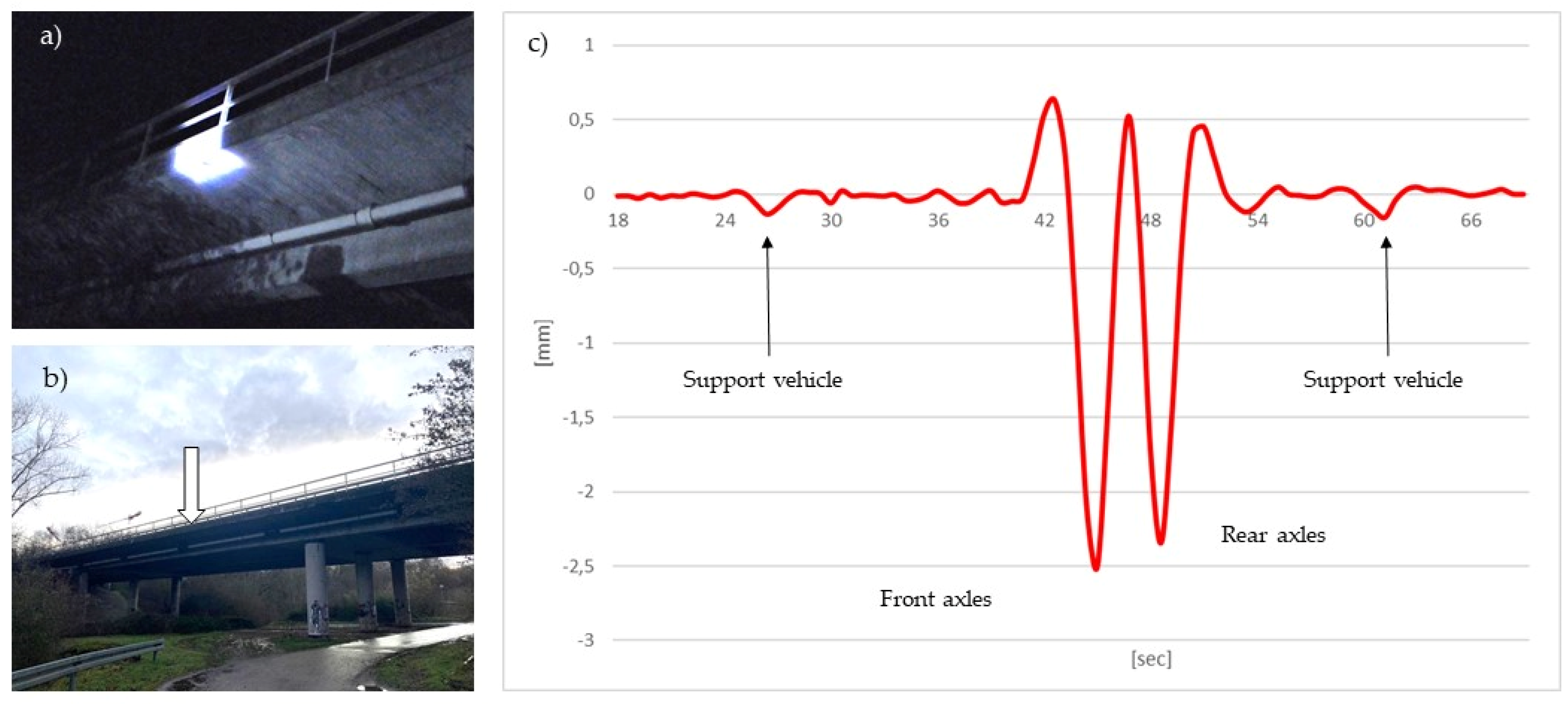
Further investigations with the MoDiTa prototype are concerned with the deformation of bridges that are loaded by large-volume or heavy transports. The Wildgraben bridge in Mainz, Germany, was observed for this purpose. It is situated on a federal road in the city area and is approximately 95 m long. The measurement was carried out at night and in cooperation with the police. The bridge was illuminated externally for the measurement. Both previously installed targets and natural targets in the middle of the bridge were monitored. The deformation was caused by the passage of a 40 m long and 90-ton heavy load transport including support vehicles. In Figure 2, both the heavy transport and the support vehicles can be seen in the displacement. Also clearly visible are the loads caused by the axles of the transporter. The different strong deformations of the axles of the truck indicate an uneven distribution of the load. Since the observed bridge section is only 35 m long, the entire heavy load transport was never on this section during the crossing. The observed deformation in the vertical direction is significantly smaller than the values calculated from an FEM, which can be attributed to the partial loading of the bridge. As this is a concrete bridge and therefore has a high damping coefficient, a frequency analysis at this point is difficult and as such was not examined further.
One of the main goals of these investigations is to check whether and in which way the bridge is suitable for the planned transport by means of prior measurements with a reference vehicle, e.g., trucks or buses. There is great potential in saving personnel costs for transport escorts, as it can be clarified in advance whether a closure of the opposite lane is necessary. Future research work will continue to focus on this topic.
5. Summary and Conclusions
In this review, an overview of imaging total stations, so-called IATS, was provided. A distinction was made between commercial and research instruments. The image processing algorithms described here show the various approaches that have been implemented to enable further automation. The field tests carried out so far also show the successful use of this measurement technology to obtain helpful information about the structure in the field of SHM for existing structures.
The sensor technology based on image information is convincing due to its contactless detection, its mobility and its short-term usability. The explained set-ups of the prototypes can easily reverse the extension of a total station to an IATS. This means that the total station can be used again for the usual applications. Thus, the field of SHM would also be possible as an area of application for smaller surveying offices. In addition, the achievable accuracy and precision is comparable or even higher than with conventional robotic total stations or GNSS measurements [14]. It should be noted that the georeferenced results are limited by the accuracy of the used total station. In comparison to terrestrial laser scanners, which capture unstructured point clouds, discrete and distinctive points on the object are observed. The great advantage here is the fast, contactless mobile deployment from the situation.
Structures do not need to be equipped with sensors or the necessary power supply. A distinctive point on the existing structure is sufficient. This means that even points that are difficult or impossible to access can be observed. However, the necessary illumination of the target point to be observed is a limiting factor. Night measurements can only be implemented with active target lighting [49]. If the lighting conditions change, the matching must be adjusted depending on the operator used. Various detection and matching algorithms have already been used successfully. However, mainly feature based, raster or area based matching methods are tested. Correlation based matching has been used most frequently. Nevertheless, other applications have also proven their worth depending on the situation. Previous research in the field of artificial intelligence leads us to expect further applications.
The temporal synchronisation of several IATS makes a contactless 3D determination of target points possible. This requires significantly more hardware. Due to the tendency of long focal lengths, measurements at greater distances from the object are possible, but atmospheric influences must be taken into account. By combining the system with a total station, it is possible to obtain directly georeferenced results. The images are taken in an oriented manner. Furthermore, the stability of the camera can be monitored and corrected by the sensors built into the total station. Commercial IATS are less capable of vibration measurements than the prototypes due to the limited speed at which the images can be captured. However, they can successfully measure them at frequencies below 15 Hz. A higher frame rate and transmission rate of the captured images would be desirable. The ability to transmit the readings wirelessly would add flexibility. Similarly, the commercial IATS offer only limited options for camera settings. Here, the images often show strong noise [64]. By omitting an eyepiece, such as the previously mentioned SX12 from Trimble, more light can reach the camera chip, improving the effectiveness of the following image analysis [28]. It is shown that the focus of image-based observation is primarily on the automation or partial automation of the geodetic monitoring, such as SHM.
Despite the advantages and disadvantages of the measurement technique shown, the results of such SHM can be used by structural engineers to detect damaged areas or to adjust their FEM using actual measured values [45].
Overall, the functionalities provided by IATS are not yet fully utilised in practice. However, the developments on the part of the manufacturers and the research community lead us to expect further application opportunities in the field of SHM.
Funding
This research received no external funding.
Data Availability Statement
The data presented in this study are available on request from the author.
Acknowledgments
I would like to thank Martin Schlüter and my supervisor Alexander Reiterer for their support. I would also like to thank Henning Heß, Stefan Hauth, Florian Thiery, Martin Heppe, Raphael Bretscher, Arno Heidelberg, Lisa Mosis and Linda Rau for their work in developing the control software.
Conflicts of Interest
The author declares no conflict of interest.
References
- Wenzel, H.; Pichler, D. Ambient Vibration Monitoring; John Wiley & Sons Ltd.: Chichester, UK, 2005; ISBN 139780470024300. [Google Scholar]
- Wenzel, H. Health Monitoring of Bridges; Wiley: Chichester UK, 2009; ISBN 9780470031735. [Google Scholar]
- Federal Ministry of Transport and Digital Infrastructure. Bericht “Stand der Ertüchtigung von Straßenbrücken der Bundesfernstraßen”: Vorlage an den Ausschuss für Verkehr und digitale Infrastruktur des Deutschen Bundestages; Federal Ministry of Transport and Digital Infrastructure: Berlin, Germany, 2016. [Google Scholar]
- Morgese, M.; Ansari, F.; Domaneschi, M.; Cimellaro, G.P. Post-collapse analysis of Morandi’s Polcevera viaduct in Genoa Italy. J. Civ. Struct. Health Monit. 2020, 10, 69–85. [Google Scholar] [CrossRef]
- Pedestrian Bridge Collapse Over SW 8th Street: Accident Report; Highway Accident Report NTSB/HAR-19/02; National Transportation Safety Board: Washington, DC, USA, 2019.
- Sawo, F.; Kempkens, E. Model-based approaches for sensor data monitoring for smart bridges. In Proceedings of the 2016 IEEE International Conference on Multisensor Fusion and Integration for Intelligent Systems (MFI), Baden-Baden, Germany, 19–21 September 2016; pp. 347–352. [Google Scholar]
- Sabato, A.; Niezrecki, C.; Fortino, G. Wireless MEMS-based accelerometer sensor boards for structural vibration monitoring: A review. IEEE Sens. J. 2017, 17, 226–235. [Google Scholar] [CrossRef]
- Gentile, C.; Ruccolo, A.; Canali, F. Continuous monitoring of the Milan cathedral: Dynamic characteristics and vibration-based SHM. J. Civ. Struct. Health Monit. 2019, 9, 671–688. [Google Scholar] [CrossRef] [Green Version]
- Gnewuch, H.; Smeu, E.; Jackson, D.A.; Podoleanu, A. Long range extensometer for civil structure monitoring using fibre Bragg gratings. Meas. Sci. Technol. 2005, 16, 2005–2010. [Google Scholar] [CrossRef]
- Minehane, M.J.; O’Donovan, R.; Ruane, K.D.; O’Keeffe, B. The use of 3D laser scanning technology for bridge inspection and assessment. Struct. Health Monit. 2014, 13, 14. [Google Scholar]
- Schill, F. Überwachung von Tragwerken mit Profilscannern. Ph.D. Thesis, Technische Univerität Darmstadt, Darmstadt, Germany, 2018. [Google Scholar]
- Marendić, A.; Paar, R.; Duvnjak, I.; Buterin, A. Determination of dynamic displacements of the roof of sports hall Arena Zagreb. In Proceedings of the INGEO 2014 6th International Conference on Engineering Surveying, Prague, Czech Republic, 3–4 April 2014. [Google Scholar]
- Stempfhuber, W. Verification of the Trimble universal total station (uts) performance for kinematic applications. In Proceedings of the Conference on Optical 3-D Measurement Techniques IX, Vienna, Austria, 1–3 July 2009; Grün, A., Kahmen, H., Eds.; ETH Zurich: Zurich, Switzerland, 2009; pp. 211–221. [Google Scholar]
- Paar, R.; Roić, M.; Marendić, A.; Miletić, S. Technological development and application of photo and video theodolites. Appl. Sci. 2021, 11, 3893. [Google Scholar] [CrossRef]
- Biliszczuk, J.; Hawryszków, P.; Teichgraeber, M. SHM system and a FEM model-based force analysis assessment in stay cables. Sensors 2021, 21, 1927. [Google Scholar] [CrossRef]
- Bürki, B.; Guillaume, S.; Sorber, P.; Oesch, H. DAEDALUS: A versatile usable digital clip-on measuring system for total stations. In Proceedings of the 2010 International Conference on Indoor Positioning and Indoor Navigation (IPIN), Zürich, Switzerland, 15–17 September 2010; pp. 1–10. [Google Scholar]
- Guillaume, S.; Clerc, J.; Leyder, C.; Ray, J.; Kistler, M. Contribution of the image-assisted theodolite system QDaedalus to geodetic static and dynamic deformation monitoring. In Proceedings of the Conference and Seminar Proceedings: 3rd Joint International Symposium on Deformation Monitoring (JISDM), Vienna, Austria, 30 March–1 April 2016; International Federation of Surveyors FIG: Copenhagen, Denmark, 2016; p. 66. [Google Scholar]
- Wagner, A.; Wasmeier, P.; Reith, C.; Wunderlich, T. Bridge monitoring by means of video-tacheometer—A case study. avn-Allgemeine Vermessungs-Nachrichten 2013, 120, 283–292. [Google Scholar]
- Ehrhart, M.; Lienhart, W. Development and evaluation of a long range image-based monitoring system for civil engineering structures. In Proceedings of the SPIE 9437, Structural Health Monitoring and Inspection of Advanced Materials, Aerospace, and Civil Infrastructure 2015, Bellingham, WA, USA, 1 April 2015. [Google Scholar] [CrossRef]
- Page, M.J.; McKenzie, J.E.; Bossuyt, P.M.; Boutron, I.; Hoffmann, T.C.; Mulrow, C.D.; Shamseer, L.; Tetzlaff, J.M.; Akl, E.A.; Brennan, S.E.; et al. The PRISMA 2020 statement: An updated guideline for reporting systematic reviews. BMJ 2021, 10, 89. [Google Scholar]
- Page, M.J.; Moher, D.; Bossuyt, P.M.; Boutron, I.; Hoffmann, T.C.; Mulrow, C.D.; Shamseer, L.; Tetzlaff, J.M.; Akl, E.A.; Brennan, S.E.; et al. PRISMA 2020 explanation and elaboration: Updated guidance and exemplars for reporting systematic reviews. BMJ 2021, 372, n160. [Google Scholar] [CrossRef]
- Luhmann, T.; Robson, S.; Kyle, S.; Boehm, J. Close-Range Photogrammetry and 3D Imaging; De Gruyter: Berlin, Germany, 2020. [Google Scholar]
- Förstner, W.; Wrobel, B.P. Photogrammetric Computer Vision: Statistics, Geometry, Orientation and Reconstruction; Springer International Publishing: Cham, Switzerland, 2016. [Google Scholar]
- Topcon Corporation. GTL-1000 English Brochure: Datasheet. 2020. Available online: https://www.topcon.co.jp/en/positioning/products/pdf/GTL-1000_E.pdf (accessed on 8 June 2021).
- Leica Geosystems AG. Leica Nova TS60: Data Sheet. 2020. Available online: https://leica-geosystems.com/de-de/products/total-stations/robotic-total-stations/leica-nova-ts60 (accessed on 4 March 2021).
- Trimble Inc. Trimble S9/S9HP Total Station: Datasheet. Available online: https://geospatial.trimble.com/products-and-solutions/trimble-s9-hp (accessed on 16 August 2021).
- Trimble Inc. Trimble SX12: Datasheet. Available online: https://geospatial.trimble.com/SX12 (accessed on 26 August 2021).
- Wagner, A. New Geodetic Monitoring Approaches using Image Assisted Total Stations. Ph.D. Thesis, Technische Universität München, München, Germany, 2017. [Google Scholar]
- Wagner, A.; Wiedemann, W.; Wasmeier, P.; Wunderlich, T. Monitoring concepts using image assisted total stations. In Proceedings of the SIG 2016—International Symposium on Engineering Geodesy, Varaždin, Croatia, 20–22 May 2016; Paar, R., Marendić, A., Zrinjski, M., Eds.; SIG 2016. Croatian Geodetic Society: Zagreb, Croatia, 2016. ISBN 953590180X/9789535901808. [Google Scholar]
- Guillaume, S.; Bürki, B.; Griffet, S.; Mainaud Durand, H. QDaedalus: Augmentation of total stations by CCD sensor for automated contactless high-precision metrology. In Proceedings of the FIG Working Week 2012, Rome, Italy, 6–10 May 2012. [Google Scholar]
- Charalampous, E.; Psimoulis, P.; Guillaume, S.; Spiridonakos, M.; Klis, R.; Bürki, B.; Rothacher, M.; Chatzi, E.; Luchsinger, R.; Feltrin, G. Measuring sub-mm structural displacements using QDaedalus: A digital clip-on measuring system developed for total stations. Appl. Geomat. 2014, 7, 91–101. [Google Scholar] [CrossRef] [Green Version]
- Schlüter, M.; Hauth, S.; Heß, H. Selbstkalibrierung motorisierter Digitalkameratheodolite für technische Präzisionsmessungen. In zfv—Zeitschrift für Geodäsie, Geoinformation und Landmanagement; DVW e.V.—Gesellschaft für Geodäsie, Geoinformation und Landmanagement, Ed.; Wißner-Verlag: Augsburg, Germany, 2009; pp. 22–28. [Google Scholar]
- Hauth, S.; Schlüter, M.; Thiery, F. Schneller und ausdauernder als das menschliche Auge: Modulare Okularkameras am Motortachymeter. avn. Allgemeine Vermessungs Nachrichten 2013, 120, 210–216. [Google Scholar]
- Atorf, P.; Heidelberg, A.; Schlüter, M.; Zschiesche, K. Berührungslose Positionsbestimmung von spiegelnden Kugeln mit Methoden des maschinellen Sehens. Zfv—Z. Für Geodäsie Geoinf. und Landmanagement 2019, 144, 317–322. [Google Scholar] [CrossRef]
- Paar, R.; Marendić, A.; Wagner, A.; Wiedemann, W. Using IATS and digital levelling staffs for the determination of dynamic displacements and natural oscillation frequencies of civil engineering structures. In Proceedings of the INGEO 2017—7th International Conference on Engineering Surveying, Lisbon, Portugal, 18–20 October 2017. [Google Scholar]
- Walser, B.H. Development and calibration of an image assisted total station. Ph.D. Thesis, ETH Zurich, Zurich, Switzerland, 2004. [Google Scholar]
- Wasmeier, P. Grundlagen der Deformationsbestimmung mit Messdaten bildgebender Tachymeter. Ph.D. Thesis, Technische Universität München, München, Germany, 2009. [Google Scholar]
- Wasmeier, P. Videotachymetrie—Sensorfusion mit Potenzial. avn. Allgemeine Vermessungs Nachrichten 2009, 116, 261–267. [Google Scholar]
- Reiterer, A.; Wagner, A. System considerations of an image assisted total station—Evaluation and assessment. avn. Allgemeine Vermessungs Nachrichten 2012, 119, 83–94. [Google Scholar]
- Wagner, A.; Huber, B.; Wiedemann, W.; Paar, G. Long-range geo-monitoring using image assisted total stations. J. Appl. Geod. 2014, 8, 223–234. [Google Scholar] [CrossRef]
- Heppe, M. Erweiterung der Multistation Leica MS50 zum Modularen Digitalkameratachymeter. Bachelor’s Thesis, University of Applied Sciences Mainz, Mainz, Germany, 2015, unpublished. [Google Scholar]
- Rottensteiner, F. Semi-Automatic Extraction of Buildings Based on Hybrid Adjustment Using 3D Surface Models and Management of Building Data in a TIS. Ph.D. Thesis, University of Technology, Wien, Austria, 2001. [Google Scholar]
- Reiterer, A.; Huber, N.B.; Bauer, A. Image-based detection and matching of homologue points using feature-vectors–functionality and evaluation in a deformation measurement system. Int. Arch. Photogramm. 2010, 38, 510–515. [Google Scholar]
- Wagner, A.; Wasmeier, P. Flächen-und Feature-basiertes Monitoring mit Videotachymetern. In Multi-Sensor-Systeme–Bewegte Zukunftsfelder; DVW—Gesellschaft für Geodäsie, Geoinformation und Landmanagement e.V., Ed.; Wißner-Verlag: Hamburg, Germany, 2014; pp. 75–88. ISBN 3896399950. [Google Scholar]
- Weinhuber, A.; Wiedemann, W.; Wasmeier, P.; Wunderlich, T. No second chance–monitoring destructive bridge load tests. In Contributions to International Conferences on Engineering Surveying. In Proceedings of the 8th INGEO International Conference on Engineering Surveying and 4th SIG Symposium on Engineering Geodesy, Conference online, 22–23 October 2020; Kopáčik, A., Kyrinovič, P., Erdélyi, J., Paar, R., Marendić, A., Eds.; INGEO&SIG 2020. Springer: Berlin/Heidelberg, Germany, 2020; pp. 29–38. [Google Scholar]
- Reiterer, A.; Wasmeier, P. Anwendungsfelder bildgebender Tachymetrie—Herausforderungen und Perspektiven. In Terrestrisches Laserscanning—TLS 2011 mit TLS-Challenge: Beiträge zum 106. DVW-Seminar am 1. und 2. Dezember 2011 in Fulda, 1st ed.; Wunderlich, T., Ohlmann-Lauber, J., Eds.; Wißner-Verlag: Augsburg, Germany, 2011; pp. 189–202. ISBN 9783896398383. [Google Scholar]
- Ehrhart, M.; Lienhart, W. Image-based dynamic deformation monitoring of civil engineering structures from long ranges. In Image Processing: Machine Vision Applications VIII; Lam, E.Y., Niel, K.S., Eds.; SPIE: Bellingham, WA, USA, 2015; pp. 139–152. [Google Scholar]
- Ehrhart, M.; Lienhart, W. Monitoring of civil engineering structures using a state-of-the-art image assisted total station. J. Appl. Geod. 2015, 9, 174–182. [Google Scholar] [CrossRef]
- Lienhart, W.; Ehrhart, M. Statische und dynamische Überwachung von Infrastrukturbauten mit kommerziellen Videotachymetern. In Proceedings of the 20. Internationale Geodätische Woche Obergurgl 2019, Obergurgl, Austria, 10–16 February 2019; Hanke, K., Weinold, T., Eds.; Wichmann VDE Verlag GmbH: Berlin, Germany, 2019; pp. 145–156. [Google Scholar]
- Ulrich, M.; Follmann, P.; Neudeck, J.-H. A comparison of shape-based matching with deep-learning-based object detection. Tm Technisches Messen 2019, 86, 685–698. [Google Scholar] [CrossRef]
- Ma, J.; Jiang, X.; Fan, A.; Jiang, J.; Yan, J. Image matching from handcrafted to deep features: A survey. Int. J. Comput Vis. 2021, 129, 23–79. [Google Scholar] [CrossRef]
- Reiterer, A. A Knowledge-Based Decision System for an On-Line Video-Theodolite-Based Multisensor System. Ph.D. Thesis, Technische Universität Wien, Wien, Austria, 2004. [Google Scholar]
- Grimm, D.; Kleemaier, G.; Zogg, H.-M. ATRplus White Paper. 2015. Available online: https://leica-geosystems.com/-/media/files/leicageosystems/products/white-papers/atrplus_wp.ashx?la=en&hash=91E09F6A1CF79DE10D9B742391F7B35F (accessed on 10 October 2021).
- X-Pointing Technology White Paper; Topcon Corporation: Livermore, CA, USA, 2013.
- Wagner, A. A new approach for geo-monitoring using modern total stations and RGB + D images. Measurement 2016, 82, 64–74. [Google Scholar] [CrossRef] [Green Version]
- Marendić, A.; Paar, R.; Damjanovic, D. Measurement of bridge dynamic displacements and natural frequencies by RTS. JCE 2017, 69, 281–294. [Google Scholar] [CrossRef]
- Neitzel, F.; Schwarz, W. Schwingungsuntersuchungen. In Ingenieurgeodäsie: Handbuch der Geodäsie, Herausgegeben von Willi Freeden und Reiner Rummel; Schwarz, W., Ed.; Springer: Berlin/Heidelberg, Germany, 2017; pp. 463–506. ISBN 9783662471883. [Google Scholar]
- Omidalizarandi, M.; Kargoll, B.; Paffenholz, J.-A.; Neumann, I. Accurate vision-based displacement and vibration analysis of bridge structures by means of an image-assisted total station. Adv. Mech. Eng. 2018, 10, 1–19. [Google Scholar] [CrossRef]
- Ehrhart, M.; Kalenjuk, S.; Lienhart, W. Monitoring of bridge vibrations with image-assisted total stations. In Proceedings of the SMAR 2017—Fourth Conference on Smart Monitoring, Assessment and Rehabilitation of Civil Structures, Zürich, Switzerland, 13–15 September 2017; ISBN 9783905594669. [Google Scholar]
- Lienhart, W.; Ehrhart, M.; Grick, M. High frequent total station measurements for the monitoring of bridge vibrations. J. Appl. Geod. 2017, 11, 1–8. [Google Scholar] [CrossRef]
- Leica Geosystems AG. Leica Nova MS50: Data Sheet. Available online: https://w3.leica-geosystems.com/downloads123/zz/tps/nova_ms50/brochures-datasheet/Leica_Nova_MS50_DAT_en.pdf (accessed on 17 June 2021).
- Omidalizarandi, M.; Neumann, I.; Kemkes, E.; Kargoll, B.; Diener, D.; Rüffer, J.; Paffenholz, J.-A. Mems based bridge monitoring supported by image-assisted total station. In Proceedings of the Joint Conferences of 5th Sensors and Models in Photogrammetry and Remote Sensing (SMPR) and 3rd Geospatial Information Research (GI Research), GeoSpatial Conference 2019, Karaj, Iran, 12–14 October 2019; pp. 833–842. [Google Scholar]
- Leica Nova MS60: Data sheet; Leica Geosystems AG: Heerbrugg, Switzerland, 2020; Available online: https://leica-geosystems.com/-/media/files/leicageosystms/products/datasheets/leica_nova_ms60_ds.ashx?la=engb&hash=DC24A3605EE8B0DED66F30240A8B63DC (accessed on 16 August 2021).
- Wiedemann, W.; Wagner, A.; Wasmeier, P.; Wunderlich, T. Monitoring mit scannenden bildgebenden Tachymetern. In Terrestrisches Laserscanning 2017(TLS 2017); DVW—Gesellschaft für Geodäsie, Geoinformation und Landmanagement e.V., Ed.; Wißner-Verlag: Augsburg, Germany, 2017; pp. 31–44. ISBN 9783957861450. [Google Scholar]
- Reiterer, A.; Lehmann, M. An image-based measurement system for quality control in civil engineering. In Proceedings of the 2007 5th International Symposium on Image and Signal Processing and Analysis, Istanbul, Turkey, 27–29 September 2007; pp. 113–118. [Google Scholar]
- Reiterer, A. Object monitoring/reconstruction with automated image-based measurement systems. In Proceedings of the 3rd IAG Symposium on Geodesy for Geotechnical and Structural Engineering and 12th FIG Symposium on Deformation Measurements, Baden, Austria, 22–24 May 2006. [Google Scholar]
- Reiterer, A.; Lehmann, M.; Miljanovic, M.; Ali, H.; Paar, G.; Egly, U.; Eiter, T.; Kahmen, H. A 3D optical deformation measurement system supported by knowledge-based and learning techniques. J. Appl. Geod. 2009, 3, 1–13. [Google Scholar] [CrossRef]
- Zschiesche, K.; Rau, L.; Schlüter, M. Optische Schwingungsmessungen: Status, Integration, Pros und Contras. In Proceedings of the GeoMonitoring, Braunschweig, Germany, 12–13 March 2020; pp. 49–63. [Google Scholar]
- Staiger, L.; Werner, Y.; Ziegler, S. Structural Health Monitoring mit Modularem Digitalkameratachymeter. Master’s Thesis, University of Applied Sciences Mainz, Mainz, Germany, 2021, unpublished. [Google Scholar]

Figure 2.
Illumination (a) and position (b) of the measured target in the middle of the bridge. (c) Representation of the vertical displacement of a target point during a heavy transport on a concrete bridge in Mainz (Germany) using prototype MoDiTa at night [69].
Figure 2.
Illumination (a) and position (b) of the measured target in the middle of the bridge. (c) Representation of the vertical displacement of a target point during a heavy transport on a concrete bridge in Mainz (Germany) using prototype MoDiTa at night [69].


| DAEDALUS ETH Zurich [16] | MoDiTa i3mainz—Mainz University of Applied Sciences [41] | University of Zagreb [14] | IATS2 Technical University of Munich [38] | |
|---|---|---|---|---|
| Tacheometer/ total station |  |  |  |  |
| TCA 1800, TCA 2003 and TDA 5005 2 | MS 50 2 | TPS1201 | based on the TCRA1200 series | |
| camera | Guppy F–080C | UI–3250 ML 1 | GoPro Hero 5 | fixed camera from manufacturer |
| resolution [pixel] | 1024 × 768 | 1600 × 1200 | up to 3840 × 2160 3 | 2560 × 1920 |
| pixel size [μm] | 4.65 | 4.5 | 1.5 4 | 2.2 |
| mgon/pixel | 1.1 | 0.4–1.0 5 | – | 0.61 |
| frame rate | 30 Hz/60 Hz (full frame/ reduced FoV) | 60 Hz/2500 Hz (full frame/ reduced FoV) | 30–240 Hz | 5–200 Hz |
| sensor | CCD | CMOS | CMOS | CMOS |
1 Based on modularity the camera is changeable. 2 Compatible to TCA, TPS, TS and MS series from the manufacturer Leica. 3 Multiple resolutions possible. Resolution mentioned in [14]: 1920 × 1080 pixel. 4 Estimated by the author. 5 Based on modularity this value is variable.
Table 2.
Comparison of the results for correlation based and shaped based matching using the MoDiTa prototype and its software. The differences (∆y, ∆x) shown represent the change in pixel position relative to the template definition.
Table 2.
Comparison of the results for correlation based and shaped based matching using the MoDiTa prototype and its software. The differences (∆y, ∆x) shown represent the change in pixel position relative to the template definition.
| Matching Method | Undisturbed Target Position | Example 1 | Example 2 |
|---|---|---|---|
| Correlation based |  |  |  |
| Deviation from the target position compared to the undisturbed target point: | ∆y = −2.91 px ∆x = 1.27 px | ∆y = −1.22 px ∆x = 1.74 px | |
| Shape based |  |  |  |
| Deviation from the target position compared to the undisturbed target point: | ∆y = 0.14 px ∆x = 0.02 px | ∆y = 0.24 px ∆x = 0.02 px | |
Publisher’s Note: MDPI stays neutral with regard to jurisdictional claims in published maps and institutional affiliations. |
© 2021 by the author. Licensee MDPI, Basel, Switzerland. This article is an open access article distributed under the terms and conditions of the Creative Commons Attribution (CC BY) license (https://creativecommons.org/licenses/by/4.0/).
Share and Cite
MDPI and ACS Style
Zschiesche, K. Image Assisted Total Stations for Structural Health Monitoring—A Review. Geomatics 2022, 2, 1-16. https://0-doi-org.brum.beds.ac.uk/10.3390/geomatics2010001
AMA Style
Zschiesche K. Image Assisted Total Stations for Structural Health Monitoring—A Review. Geomatics. 2022; 2(1):1-16. https://0-doi-org.brum.beds.ac.uk/10.3390/geomatics2010001
Chicago/Turabian StyleZschiesche, Kira. 2022. "Image Assisted Total Stations for Structural Health Monitoring—A Review" Geomatics 2, no. 1: 1-16. https://0-doi-org.brum.beds.ac.uk/10.3390/geomatics2010001