
Biomimetic Full-Thickness Skin-on-a-Chip Based on a Fibroblast-Derived Matrix


1
Instituto de Tecnologia Química e Biológica (ITQB), Universidade Nova de Lisboa, Avenida da República, Estação Agronómica Nacional, 2780-157 Oeiras, Portugal
2
Instituto de Biologia Experimental e Tecnológica (IBET), 2781-901 Oeiras, Portugal
*
Author to whom correspondence should be addressed.
Micro 2022, 2(1), 191-211; https://0-doi-org.brum.beds.ac.uk/10.3390/micro2010013
Submission received: 21 January 2022
/
Revised: 7 March 2022
/
Accepted: 9 March 2022
/
Published: 12 March 2022
(This article belongs to the Section Microscale Biology and Medicines)
Abstract
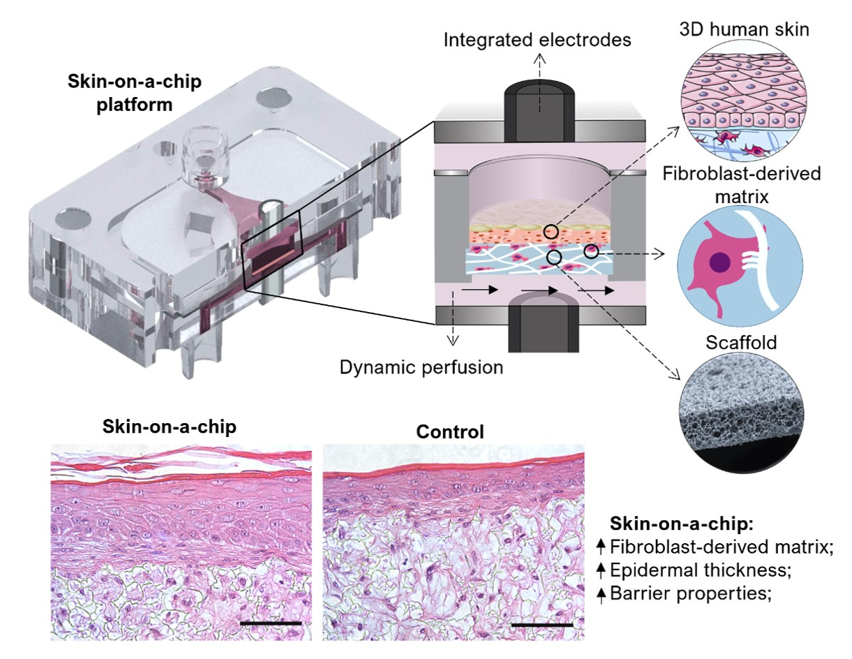
:Current commercially available in vitro skin models do not fully reproduce the structure and function of the native human skin, mainly due to their use of animal-derived collagen and their lack of a dynamic flow system. In this study, a full-thickness skin-on-a-chip (SoC) system that reproduces key aspects of the in vivo cellular microenvironment is presented. This approach combines the production of a fibroblast-derived matrix (FDM) with the use of an inert porous scaffold for the long-term, stable cultivation of a human skin model. The culture of a dermal compartment under fluid flow results in the increased synthesis and deposition of major FDM proteins, collagen I, and fibronectin, compared to tissues cultured under static conditions. The developed SoC includes a fully differentiated epidermal compartment with increased thickness and barrier function compared to the controls. Contrary to other SoC platforms that include a collagen-based matrix, the described model presents superior stability and physiological relevance. Finally, the skin barrier function was quantitatively evaluated via in situ transepithelial electrical resistance (TEER) measurements and in situ permeation tests. The SoC model presents a significantly higher TEER and lower permeability to FITC-dextran. In the future, this innovative low-cost platform could provide a new in vitro tissue system compatible with long-term studies to study skin diseases and evaluate the safety and efficacy of novel drugs and technologies.

1. Introduction
The global topical drug delivery market is growing fast due to the increasing prevalence of chronic skin diseases [1]. New and better technologies for topical drug delivery are also expected to boost the growth of this market [2]. Animal models have been used worldwide to test the efficacy and toxicity of topical drugs. However, animal experimentation raises important ethical and regulatory concerns [3,4]. In addition, there is a lack of accuracy of the animal-to-human extrapolation, with approximately 90% of the drug candidates that appear safe and effective in animal studies failing to win approval when tested in humans [5,6,7]. These factors resulted in an increasing need to replace and/or complement animal testing with physiologically relevant reconstructed human skin models suitable for topical drug delivery and disease modeling [8,9].
Techniques for culturing three-dimensional (3D) skin cells have been developed, resulting in significant advancements in skin tissue engineering [9,10]. However, current commercially available human skin models still lack complexity and present weaker barrier properties than in vivo human skin [11]. Organ-on-a-chip (OoC) technology aims to surpass the limitations of conventional cell-based culture platforms and increase the predictive power of in vitro models by creating customized cellular microenvironments with precise fluidic, mechanical, and structural control [12]. Moreover, integrating sensors in OoC allows real-time monitoring of tissue viability and function [13].
In the last few years, several skin-on-a-chip (SoC) platforms have been reported and their physiological relevance has been shown. However, most of these platforms have been limited to maintaining transferred skin tissues (e.g., skin biopsies) to increase their longevity and/or establish a co-culture with other organ models [14,15,16,17,18,19,20]. These studies provide valuable information regarding the potential of SoC devices for clinical and testing purposes. However, the integration of models previously developed off-chip limits the potential benefits of the dynamic culture. More recently, skin models generated on-chip have been reported. Wufuer et al. developed a SoC consisting of 3 cell layers (keratinocytes, fibroblasts, and endothelial cells) separated by two porous membranes to simulate inflammation and edema [21]. Ramadan et al. further explored the potential of the SoC devices by including an immune component, describing the interaction between the HaCaT cell line and a monocytic cell line in a bi-channel microfluidic device [22]. Although these studies replicated some important features of healthy and diseased skin, they included monolayer systems that do not replicate the 3D environment of in vivo human skin.
Only a handful of publications have reported OoC devices for 3D skin tissue formation inside the platform. Mori et al. fabricated a culture device composed of anchoring structures and nylon wires across the device’s connectors to produce a full-thickness human skin model (FTSm), including the dermis and the epidermis [23]. This study was an important first step in developing 3D FTSm inside the platform to mimic in vivo vascularization. However, the limitations of using collagen to develop the dermal compartment were apparent. Collagen contraction made it necessary to increase the device’s complexity and compromised the model’s reproducibility, frequently resulting in clogged channels. Lee et al. developed 3D FTSm inside an SoC device composed of two polydimethylsiloxanes (PDMS) fluidic chambers [24]. The group also reported skin contraction during the differentiation process, resulting in detachment of the scaffold. Moreover, the stratum corneum of the SoC models was less homogeneous than the controls.
Both the above-mentioned studies highlight the limitations of using natural hydrogels to generate the dermal compartment inside an OoC device. These systems reported fibroblast-mediated contraction and matrix degradation leading to distortion and disruption of the skin model. Moreover, by including dermal compartments comprising exclusively of animal-derived collagen type I, they are not fully representative of the in vivo extracellular matrix (ECM), which includes multiple types of collagens, fibrous proteins, and proteoglycans. Recently, Sriram et al. used a combination of fibrin and polyethylene glycol (PEG) to produce a stable dermal component capable of sustaining the epidermis without signs of contraction [25]. The group produced an SoC with improved epidermal differentiation and barrier function.
Here, we present an alternative approach to generating a 3D full-thickness SoC with a stable dermal compartment representing the in-vivo microenvironment. Recently, our group developed an OoC with integrated electrodes for the development and real-time monitoring of biological barriers [26]. As a proof of concept, transepithelial resistance (TEER) was measured during the formation of an epidermis inside the chip. Here, we study the impact of dynamic perfusion on both dermis and epidermis formation by performing histological and functional analyses. In the described approach, an inert porous scaffold is integrated into the device, where dermal cells are seeded and stimulated to produce their own endogenous ECM (fibroblast-derived matrix, FDM). This process results in a mechanically stable structure and excludes animal-derived hydrogels. Furthermore, the SoC platforms described in the literature are irreversibly sealed, usually through plasma bonding, making it difficult the complete tissue retrieval for endpoint assays (e.g., histological analysis and immunofluorescence). The described SoC includes a removable culture insert and interchangeable modules (e.g., for permeation studies).
2. Materials and Methods
2.1. Fabrication and Assembly of the SoC Device
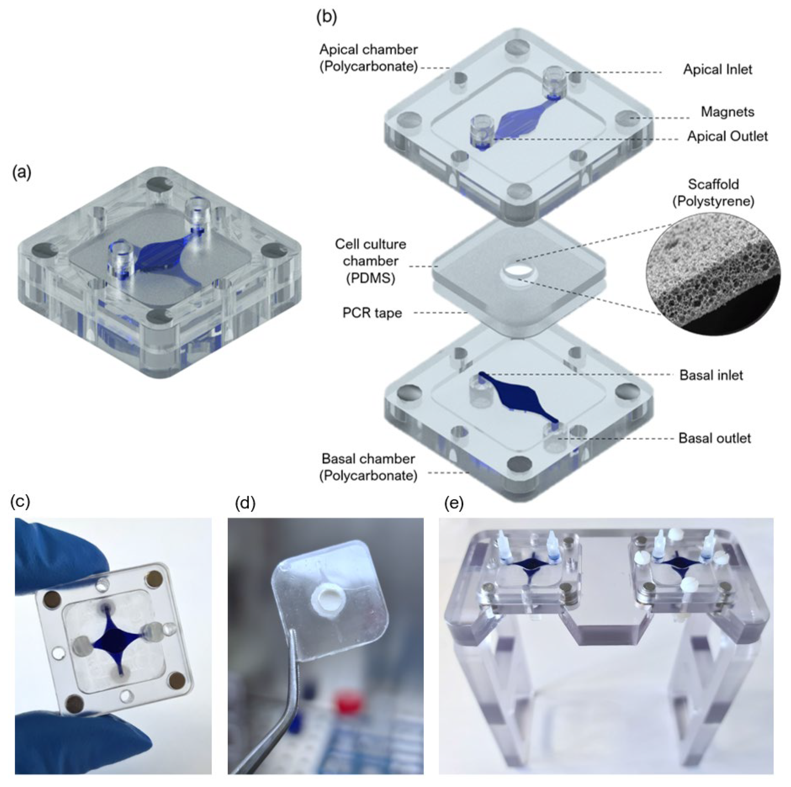
A SoC device with a modular architecture and a “user-friendly” approach was designed and fabricated to produce an FTSm and in situ drug testing. The device is composed of 3 main layers: two fluidic compartments (apical and basal) and a central insert layer for cell culture. The design of the SoC was optimized to ensure stability during long-term skin culture while providing a flexible and modular geometry compatible with different studies. A closed schematic and exploded view of the SoC device are shown in Figure 1a,b, respectively.
The protocol for the fabrication of the device was previously described by our group [26]. Briefly, the apical and basal chambers were fabricated through a combination of computer numerically controlled (CNC) micromachining and laser cutting (Xometry Europe GmbH, Ottobrunn, Germany). The apical and basal layers were constructed in polycarbonate (31.5 × 31.5 × 4 mm, length x width x height) and included a central cavity designed to accept the cell culture layer (21 × 21 × 1 mm, length x width x height). The dimensions of the fluidic channels were 0.9 × 0.6 mm (width × heigh), and the central circular perfusion chambers were 5 × 0.6 mm (diameter × heigh). For the access ports, mini female luer interfaces (microfluidic ChipShop, Jena, Germany) were glued to the inlets and outlets in both the upper and lower polycarbonate housings.
To obtain the PDMS layer for cell culture that could fit in the polycarbonate cavities, dedicated molds were fabricated using CNC machining and laser cutting. The molds were filled with degassed PDMS prepolymer mixed with a curing agent (Sylgard 184, Dow Corning, Midland, MI, USA) at a 10:1 (w/w) base to catalyst ratio and placed in an oven for 12 h at 65 °C. Polystyrene scaffolds (Alvetex®, REPROCELL Europe Ltd., Glasgow, UK) were cut in a circular shape 6 mm diameter and sandwiched between the PDMS insert layer and a double-sided adhesive tape (PCR tape, ThermalSeal RTS®, Sigma-Aldrich, St. Louis, MO, USA) with 21 × 21 mm and an open central region of 5 mm for cell culture. The PCR adhesive tape was chosen due to its biocompatibility for cell culture, transparency, and good sealing properties. To better seal the PDMS insert against the polycarbonate housing and avoid leakage, the PCR tape was covered with a thin PDMS layer. The chips were sterilized using UV radiation. The lids, insets, tubing, and fittings were sterilized in an autoclave before assembling them onto the chip on the setup day. The final assembled culture platform is shown in Figure 1c, with blue dye used to identify the distinct basal and apical compartments. Figure 1d shows the PDMS cell culture layer with a central polystyrene scaffold. Figure 1d shows two SoC devices placed in dedicated support.
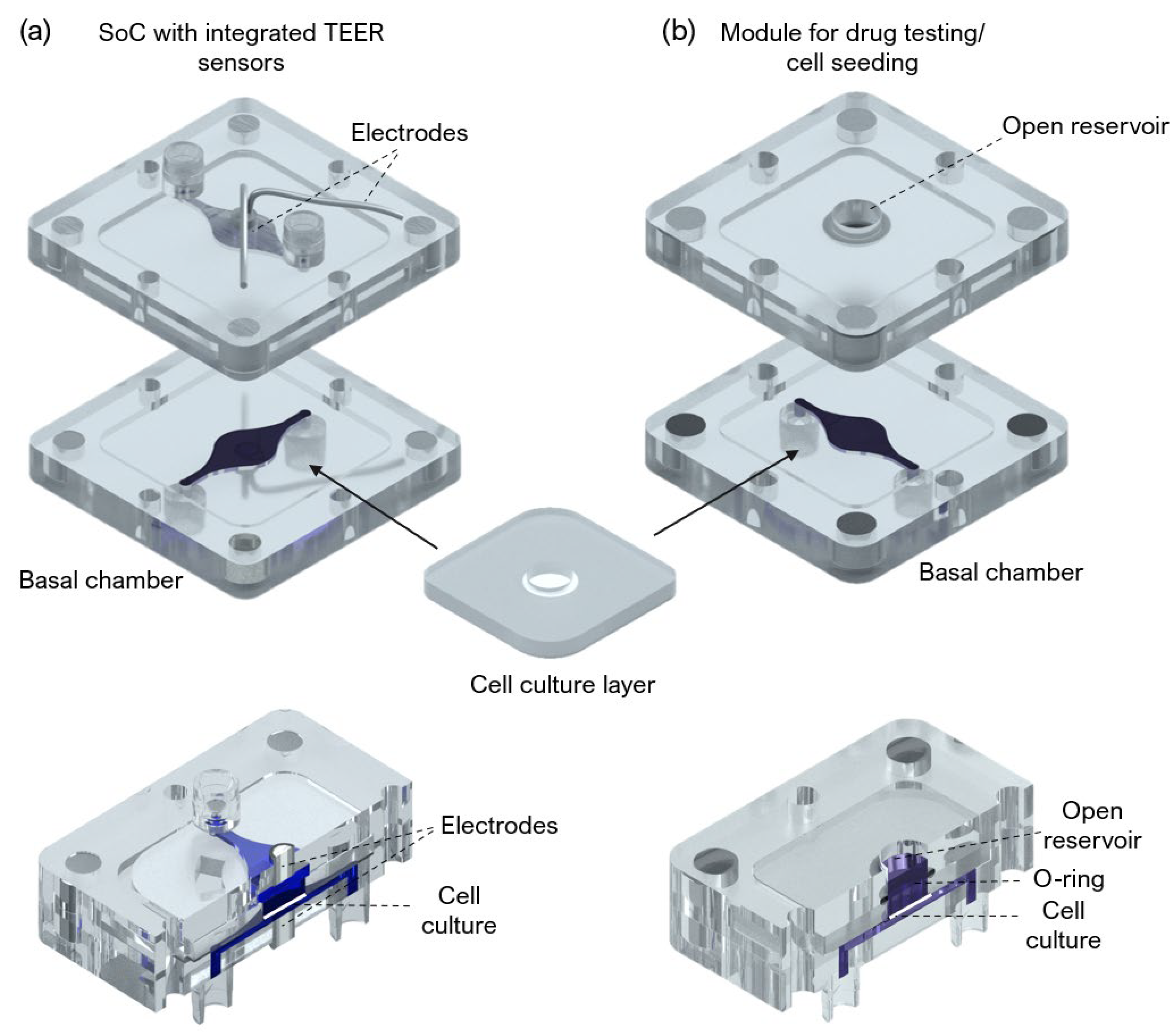
An SoC device with integrated electrodes for TEER measurement and a module compatible with drug testing and direct cell seeding were also designed and fabricated (Figure A1). The TEER module includes Ag/AgCl-sintered pellet electrodes concentric placed in both apical and basal perfusion layers as described by Zoio et al. [26]. A module for in situ drug testing and/or cell seeding consisted of a top polycarbonate housing with embedded magnets and a central reservoir, fabricated using CNC machining (Xometry Europe GmbH, Ottobrunn, Germany). A 6 mm diameter O-ring was added to ensure a leakage-free seal around the culture insert. The chips were sterilized using UV radiation.
2.2. Computational Fluid Dynamic Simulations
To characterize the hydrodynamics of the developed SoC, 3D models of the fluidic compartments and scaffold domain were generated with CAD (AutoCAD, Waltham, MA, USA) and imported to COMSOL Multiphysics™ (COMSOL Multiphysics GmbH, Gottingen, Germany) for finite element analysis (FEA).
The fluid was assumed as a homogeneous, incompressible Newtonian fluid. The density of the culture medium was assumed to be the same as water, 993.2 kg/m3, and the dynamic viscosity was 7.8 × 10⁻³ kg/m/s at a temperature of 37 °C. The boundary conditions were defined based on the inlet conditions for the flow rate (2 μL/min) and ambient pressure outlet conditions. COMSOL’s Free and Porous Media Interface was used for modeling a combination of porous media and free flow domain. The Navier-Stokes equation (incompressible flows) was used to model the free flow in the apical and basal chambers, and the Brinkman equations were applied to the porous domain (the scaffold layer). At the interface between free and porous media flow, the implemented boundary conditions between these domains enforce continuity for the velocity and the pressure. For all solid walls, no-slip boundary conditions were set. For all models, the “extra fine” mesh (under COMSOL calibration for general physics) was chosen, automatically assigning mesh sizes. Figure A2 shows the results obtained by performing FEA using the designed SoC under double tangential flow.
2.3. Primary Cells and Cell Maintenance
Primary human dermal fibroblasts isolated from neonatal foreskin (HDFn, CellnTec; Stauffcherstr, Switzerland) were maintained in Fibroblast Growth medium (FGM) composed of Iscove’s Modified Dulbecco’s Medium (IMDM, Gibco, Waltham, MA, USA) supplemented with 10% fetal bovine serum (FBS, Gibco, Waltham, MA, USA), at 37 °C in a 5% CO2 humidifier, following supplier’s instructions. HDFns were used for up to 10 passages and subcultured at a 90% confluency.
Primary human epidermal keratinocytes isolated from neonatal foreskin (HEKn, Gibco, Waltham, MA, USA) were maintained in keratinocyte growth medium (KGM) composed of EpiLife medium (Gibco, Waltham, MA, USA), supplemented with 0.06 mM calcium and keratinocyte growth factor (HKGS, Gibco, Waltham, MA, USA), at 37 °C in a 5% CO2 humidified incubator. The KGM medium was replaced every other day until the cells reached 50% confluency. At this point, the medium was replaced every day. 6th passage HEKns were used, subcultured at 70–80% confluency. All cultures were routinely monitored for contaminations.
2.4. Generation of the Dermal Equivalents
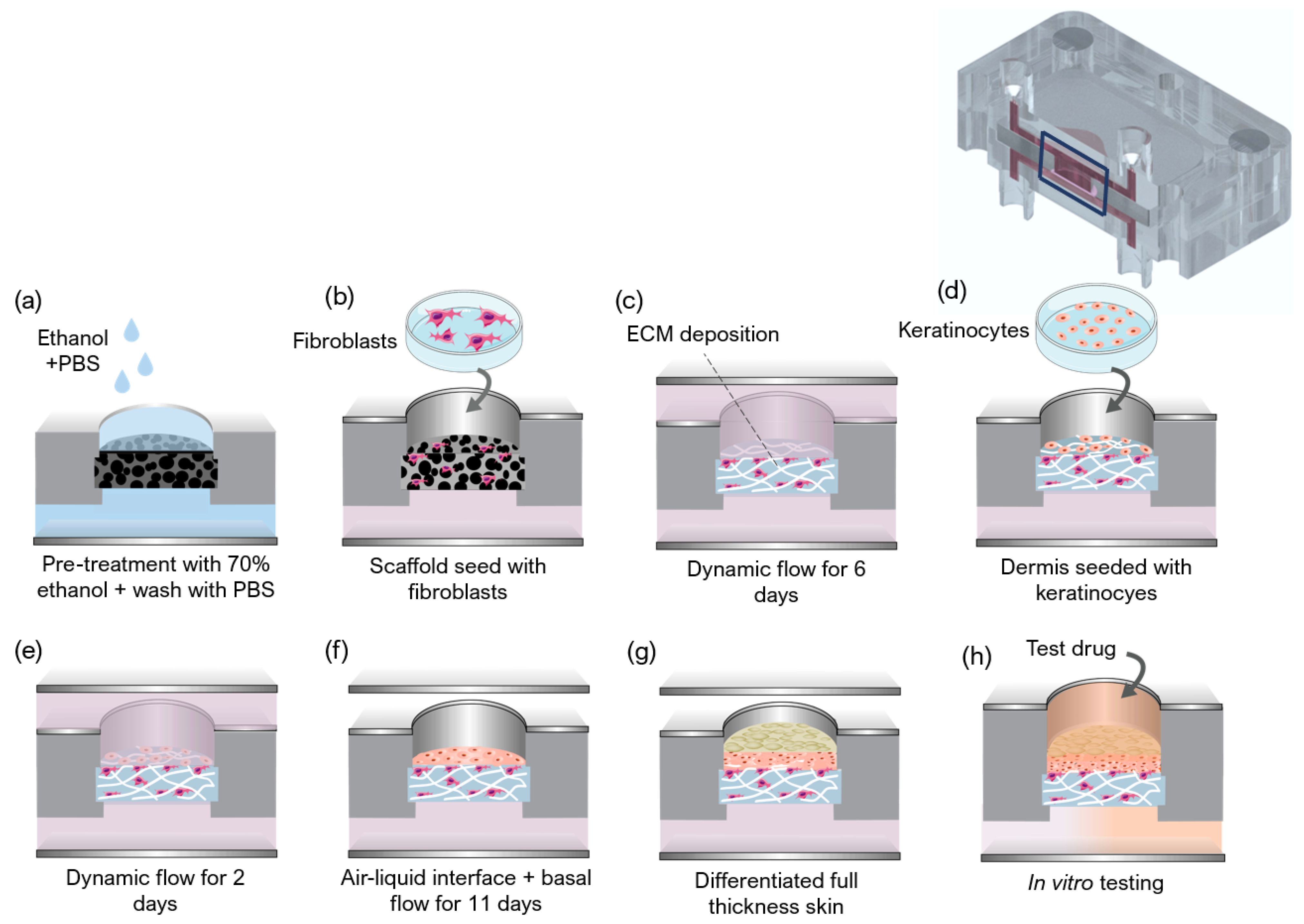
The protocol used to generate a full-thickness and fully human skin model inside the OoC is depicted in Figure 2. The process can be divided into three main steps: the development of a mature dermis; the culture of an epidermal cell monolayer on top of the dermis under submerged conditions; and the culture of the epidermis at the air-liquid interface (ALI) until a fully-differentiated skin is produced.
The formation of the fully-human dermal equivalent was achieved by seeding HDFns within the Alvetex® scaffolds (REPROCELL Europe Ltd., Glasgow, UK) and by stimulating them to proliferate and secrete endogenous dermal FDM (Figure 2a–c) [27]. The scaffolds were pre-treated with 70% ethanol to render its hydrophilicity followed by two washes with phosphate-buffered saline (PBS) (Figure 2a). Different concentrations of HDFns (5 × 10⁶, 10 × 106, 20 × 106 cells/mL) were seeded directly on the scaffolds in 30 μL FGM medium and incubated at 37 °C, in a humidified atmosphere of 5% CO2 for 1.5 h (Figure 2b). After the cells adhered to the scaffold’s structure, the cell culture layer was introduced into the device, between the apical and basal chambers. The single tangential flow configuration was achieved by connecting the inlet ports of the lower compartments to 3-stop Tygon® LMT-55 Tubing (Ismatec; Cole-Parmer GmbH, Wertheim, Germany) mounted on a multichannel peristaltic pump (LABV1 with an MC10 pump head, Baoding Shenchen Precision Pump Co., LTD, Baoding, China). The tubing was connected to a media reservoir to supply the culture media to the SoC. A filter (Whatman GmbH, Dassel, Germany) placed at the reservoir allowed permanent gas exchange. The medium was pumped from the reservoir through the inlets of the basal chambers and left the SoC through the basal outlets. The inlets and outlets of the apical chamber were closed with mini-luer plugs (microfluidic ChipShop, Jena, Germany). The dermal equivalent in the culture chamber of the device was perfused with FGM + 100 μg/mL ascorbic acid 2-phosphate (Sigma-Aldrich, St. Louis, MO, USA) at a flow rate of 1.5 μL/min for 6 days (Figure 2c).
Dermal equivalents were maintained on fabricated supports, which could fit in 6-well plates, and kept under static conditions as controls. After the cell adhesion period, 6 mL of FGM + 100 μg/mL ascorbic acid 2-phosphate was applied to the bottom of each well to flood the cell culture insert. The controls were maintained for 6 days, the medium changed after 3 days, to study the formation of the dermal equivalent without perfusion.
2.5. Generation of the FTSm
The FTSm was generated by seeding HEKn cells onto the dermal equivalents in KGM containing high calcium concentration (1.5 mM). HEKns were harvested by trypsinization, and 30 µL of cell suspension 5.0 × 10⁶ cells/mL was pipetted directly on top of the mature dermis (Figure 2d). This was followed by a 3-h incubation period for cell adhesion at 37 °C in a 5% CO2 incubator. After this period, double-sided perfusion was established using the perfusion module (Figure 2e). For this, the inlet ports on the top and lower compartments were connected to the tubing mounted on the peristaltic pump and connected to a media reservoir with supplemented KGM medium. The medium was pumped from the reservoir through the inlets of the apical and basal chambers and left the SoC through the apical and basal outlets. With this configuration, the tissue in the culture chamber of the device was double-sided perfused with KGM at a flow rate of 2 μL/min. The formation of a differentiated epidermis was achieved by pumping the medium only through the basal chamber while pumping air through the apical chamber. The ALI medium was composed of KGM containing 1.5 mM calcium, supplemented with 10 ng/mL KGF (Keratinocyte growth factor, Gibco, Waltham, MA, USA) and 100 μg/mL ascorbic acid 2-phosphate A flow rate of 1.5 μL/ml was established for medium and airflow, maintained up to a further 11 days.
The controls were maintained under submerged conditions in KGM containing high calcium concentration (1.5 mM), using the fabricated supports 6-well plates, without perfusion. After 48 h, the models were raised as well. For the controls, the FTSm were raised to ALI by removing the medium in the upper compartment and culture in 4 mL KGM containing 1.5 mM calcium, supplemented with 10 ng/m and 100 μg/mL ascorbic acid 2-phosphate. This volume resulted in the basal side of the skin tissue being in contact with the media and the upper surface to remain exposed to the air. The incubation continued at 37 °C in 5% CO2 for 11 days, changing the media every two days, to allow the formation of an FTSm.
2.6. Histochemistry and Immunofluorescence Analysis
The reconstructed tissues were fixed in 10% neutral buffered formalin (Sigma) immediately after being taken out of the chip. The samples were embedded in paraffin to allow for transverse sectioning. Paraffin-embedded sections (5 µm-thick) were de-paraffined and re-hydrated for morphological evaluation by staining with haematoxylin and eosin (H&E) through standard methods. Immunofluorescence analysis was performed to detect significant markers related to dermal maturation and epidermal differentiation. Skin sections were deparaffinized using HistoChoice® (Sigma-Aldrich) and incubated in a dry chamber at 65 °C for 30 min. Then, skin sections were hydrated for 5 min in a gradient of ethanol solutions (100%, 96%, and 70%). The antigen retrieval was performed by heating in citrate buffer (pH = 6). For anti-collagen IV antibody, the antigen retrieval was followed by proteinase K [20 µg/mL in Tris-EDTA (TE) Buffer] incubation for 30 s at 37 °C with 10 min of cooling at room temperature. Immunofluorescence staining of sections was performed using the following primary antibodies: 1:500 anti-collagen IV (Abcam, Cambridge, UK), 1:10 anti-cytokeratin 10 (Progen), 1:1000 anti-cytokeratin 14 (Abcam), 1:100 anti-cytokeratine 15 (Sigma-Aldrich), 1:250 anti-fibronectin (Abcam), 1:50 anti-filaggrin (Invitrogen, Waltham, MA, USA) and 1:100 anti-collagen I (Abcam) diluted in a solution with PBS-BSA 1% with overnight incubation in a humidified chamber at 4 °C. Secondary antibodies, 1:1000 Alexa Fluor® 488 Goat Anti-Rabbit IgG (Invitrogen) or 1:1000 FITC Goat Anti-Mouse IgG (Sigma-Aldrich), diluted in a solution with PBS-BSA 1%, were then added with an incubation of 2 h. Nuclei were stained with 1 μg/mL of 4,6-diamidino-2-Phenylindole (DAPI, Invitrogen), and slides were mounted using Vectashield (Vector Laboratories). Images were obtained using the Nikon Eclipse TE2000-S fluorescence microscope (Nikon Instruments, Melville, NY, USA) and analysed with the ImageJ software.
2.7. TEER Measurements
TEER was measured using the SoC with integrated tetrapolar electrodes and an EVOM volt-ohmmeter (WPI Europe, Friedberg, Germany). The volt-ohmmeter supplies an AC square-wave current of ±10 µA at 12.5 Hz through the outer current-carrying electrodes and measures the voltage drop across the inner voltage-sensing electrodes. This technique was used to measure the TEER of 3 batches of FTSm generated on-chip, and 3 batches of FTSm generated off-chip (controls). TEER was recorded after 11 days of culture at ALI, following completion of the FTSm. For the controls, the cell culture layer was removed from its original supports and transferred to an SoC module with integrated electrodes. The ALI was interrupted by pumping PBS into the basal and apical chambers to bridge an electrical connection between top and bottom sensors. TEER was recorded for 5 min to achieve stabilisation at room temperature. TEER was also measured for a blank scaffold to take into account the contribution of the geometry of the fluidic chambers and subtracted from each recording. The values in Ω·cm2 were obtained by multiplying the obtained electrical resistance by the skin surface area.
2.8. Permeation Assays
Permeation assays were conducted following TEER measurement for 3 batches of FTSm generated on-chip, and 3 baches of FTSm generated off-chip. The drug testing module was used to perform in situ permeation experiments. The culture media reservoir was replaced with a reservoir containing the receiver solution (PBS) supplied in the basal compartment. The perfusates samples flowing out from the basal chamber were collected directly in a 96-well plate, according to predetermined time intervals. The donor compartment was filled with 100 µL of fluorescein isothiocyanate (FITC)—dextran with an average molecular weight of 4.4 kDa (Sigma-Aldrich) at a 2.5 mg/mL concentration in PBS. The donor compartment was covered with PCR tape to minimize evaporation. The perfusate was collected into a different well every 30 min for 6 h after applying the donor solution. This was achieved by pumping the receiver solution at an 8 µL/min flow rate. The concentrations of the skin-permeated FITC-dextran were determined by fluorescence spectroscopy (SLM 8100, SLM Instruments Inc., Rochester, NY, USA) at excitation and emission wavelengths of 495 and 519 nm, respectively. The concentrations were calculated using a calibration curve and converted in cumulative amounts that permeated per unit skin surface area. The slope of the linear portion of the area-normalized cumulative amount profiles were used to calculate the permeability coefficient, following Fick’s first law.
2.9. Statistical Analysis
Quantitative data are presented as a mean ± standard deviation (SD). The statistical significance was calculated using the one-way ANOVA. Statistical differences are noted as *, ** or ***, corresponding to p < 0.05, p < 0.01 and p < 0.001, respectively.
3. Results
3.1. Dermal Maturation Affects Skin Development
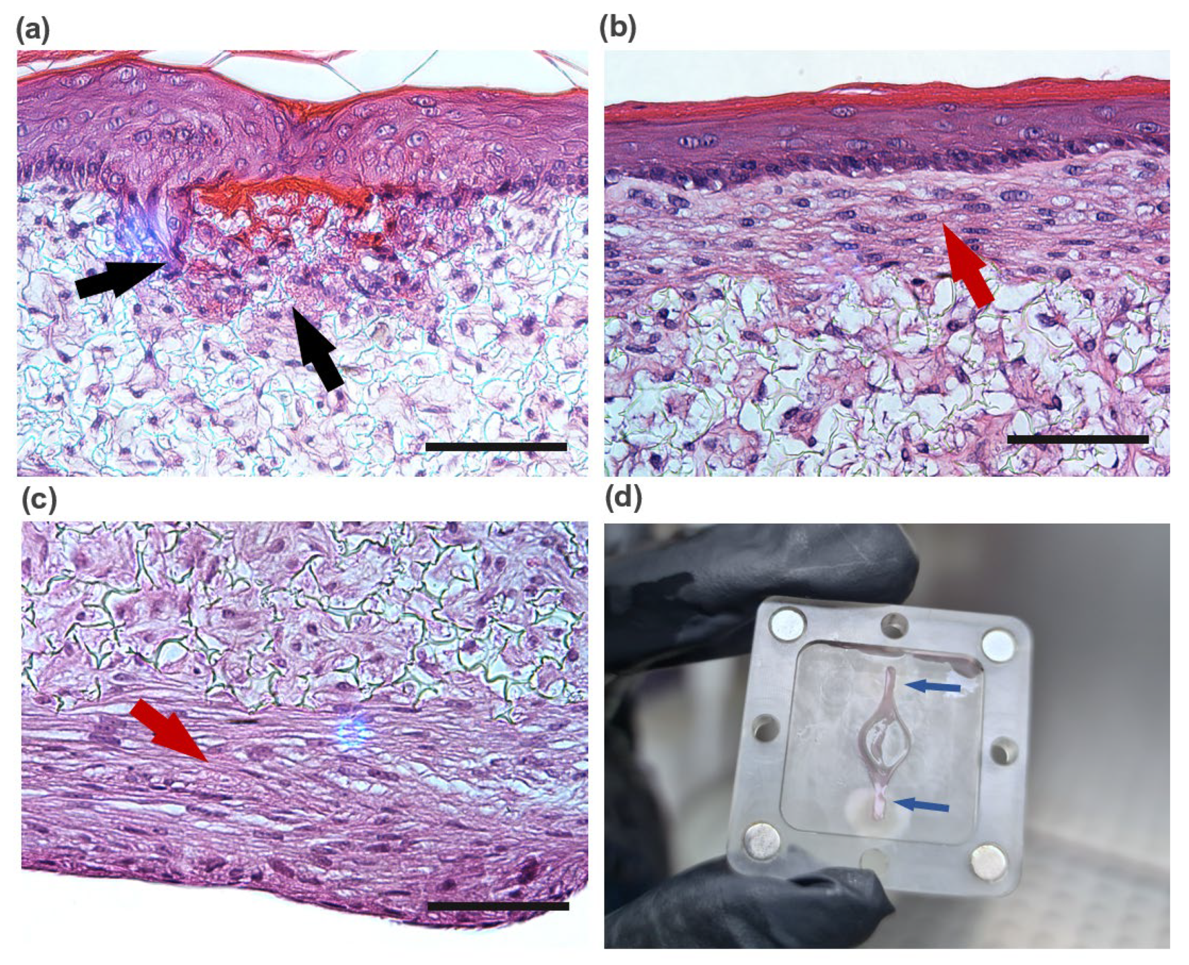
Experiments were performed to determine the optimal dermal HDFn concentration to produce a dermal construct capable of supporting the epidermis and avoiding HEKn infiltration. The influence of the dermis maturation on the epidermis formation was evaluated by seeding HEKns on top of dermal equivalents seeded with different concentrations of HDFns (5, and cells/mL). HDFns were seeded on-chip and maintained under a single tangential flow for 6 days, followed by generation of the FTSm off-chip. Figure 3 shows cross-sections of FTSms generated using dermal constructs with 5 (Figure 3a) and cells/mL (Figure 3b).
FTSms generated with a lower HDFn cell concentration resulted in the formation of an immature dermal compartment. The epidermis grown on this immature dermal construct shows HEKn infiltration, resulting in areas of epidermal disorganization. FTSm generated using a higher HDFn concentration presents a differentiated and organized epidermis. No signs of keratinocyte infiltration can be seen in these constructs. However, a thick layer of fibroblasts and FDM can be seen on both sides of the scaffold, reaching a thickness of 105 ± 20 µm at the apical side and 160 ± 45 µm at the basal side of the scaffold (Figure 3c). Approximately half of the SoC devices generated with the highest dermal cell concentration led to an FDM deposition not only in the apical and basal sides of the scaffold structure but also in the basal chamber of the device. Figure 3d shows the SoC device with excessive FDM deposition and clogged inlets and outlets. The same phenomenon did not occur for lower HDFn concentrations. In particular, a concentration of cells/mL cultured for 6 days minimized HEKn infiltration and, simultaneously, did not result in excessive FDM deposition. Therefore, this condition was used in the following experiments.
3.2. Dynamic Flow Stimulates Production of Endogenous FDM
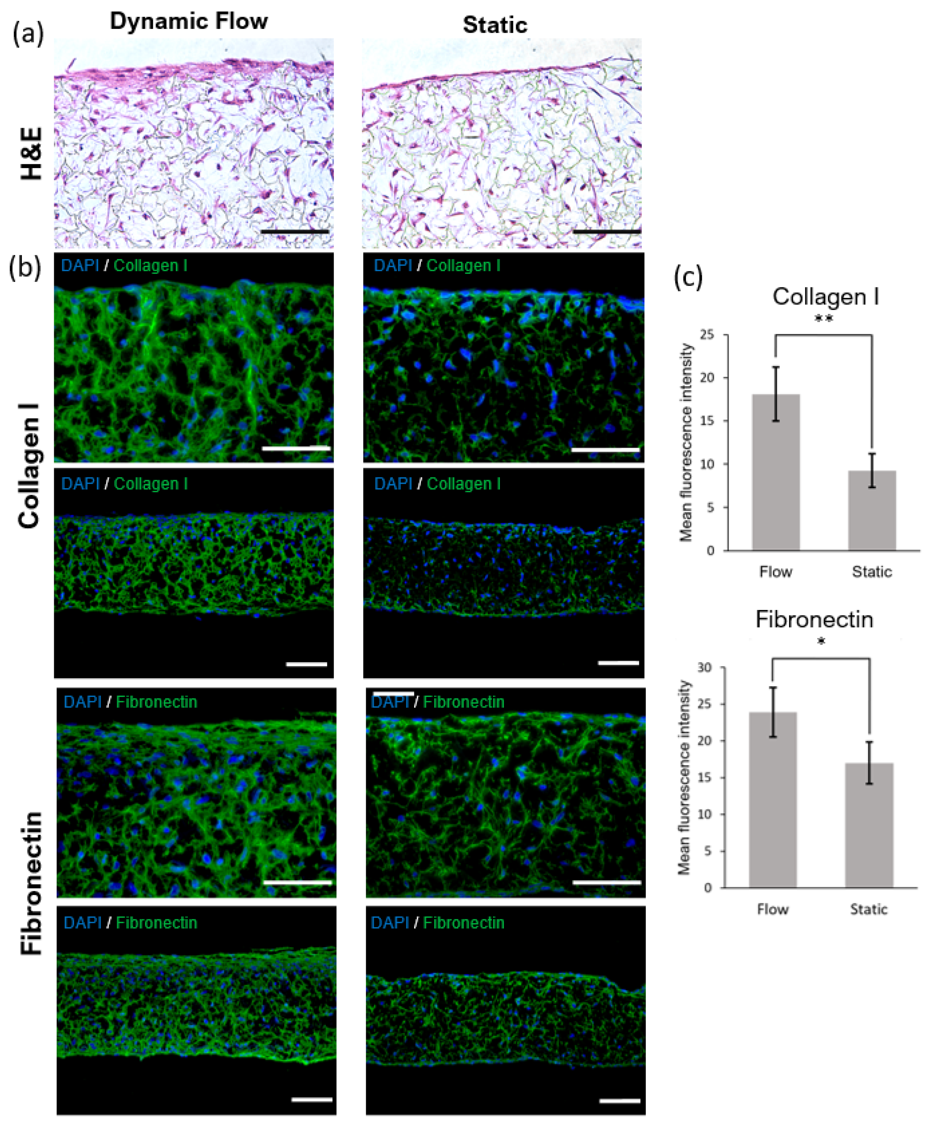
The effect of dynamic flow culture on cell proliferation and FDM deposition inside the scaffold structure was evaluated using histological and immunofluorescence analysis (Figure 4). The dermal compartment was generated and maintained on-chip for 6 days and compared with static controls. During the culture of the dermal compartment, HDFns are stimulated to produce endogenous FDM, which builds up and accumulates inside the scaffold. The histological analysis shows that, for both flow and static conditions, dermal HDFns present a relatively homogenous distribution within the scaffold’s structure (Figure 4a). Under the flow conditions, dermal HDFns proliferated inside the scaffold and also grew on the apical side of the structure. This can be seen in the representative H&E images through the presence of a thicker layer of HDFns and FDM deposited at the apical side of the scaffold, pointing to an increased proliferation of cells and enhanced FDM deposition.
The influence of the dynamic flow was further evaluated by the immunostaining of two major ECM proteins, collagen I and fibronectin (Figure 4b). Expression of collagen I and fibronectin were detected within the dermal equivalents generated under static and flow conditions. Immunostaining of fibronectin and collagen I showed increased expression of these proteins in the dermis generated under dynamic flow conditions compared to dermis generated under static conditions (Figure 4c).
3.3. OoC Technology Increases Epidermal Thickness and Improves Terminal Differentiation
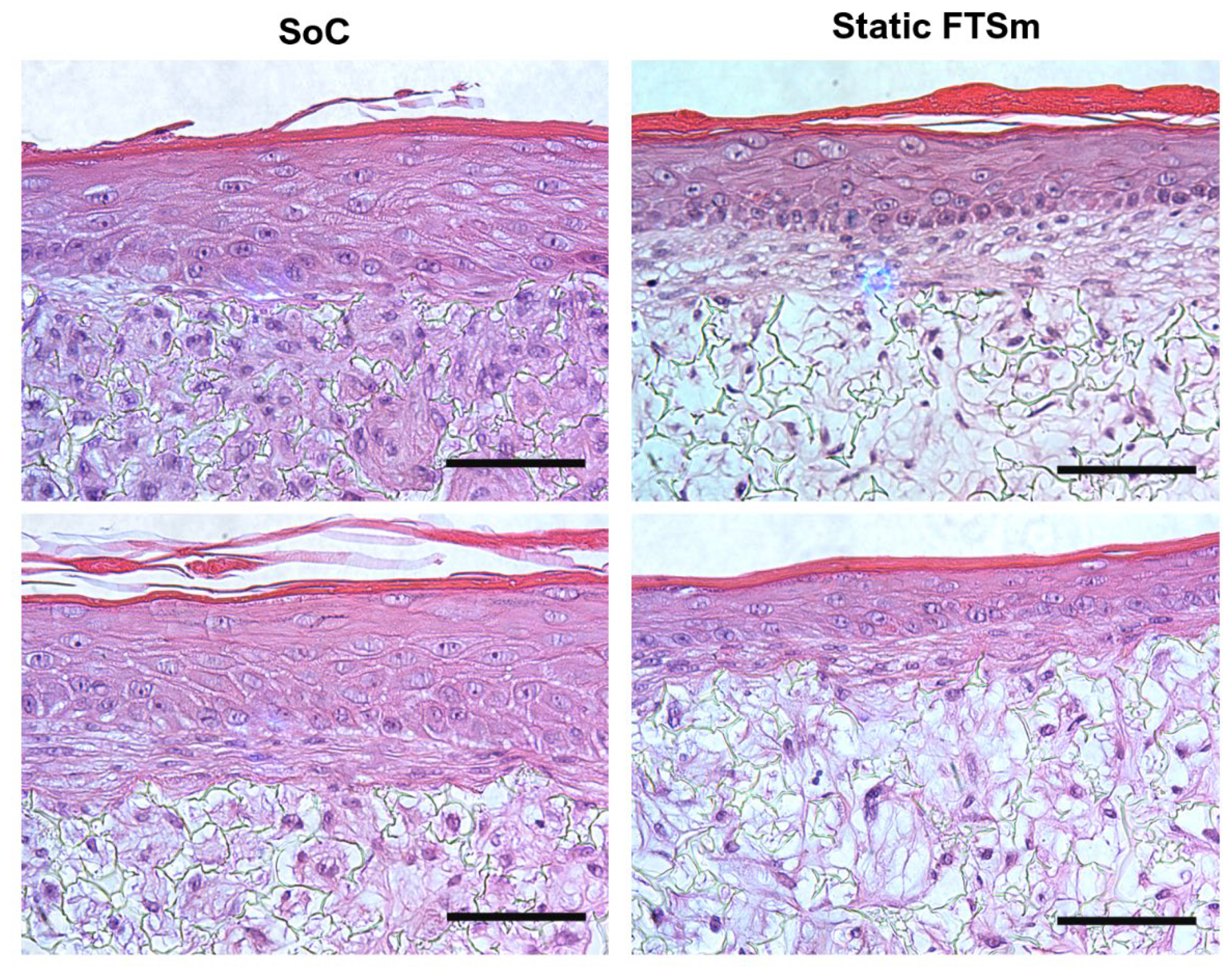
The FTSm were generated by seeding HEKn cells onto the dermal equivalents and maintaining the culture on-chip for 2 days under submerged conditions, followed by 11 days at the ALI, until complete skin development. Figure 5 shows representative histological sections performed for both the SoC and the static model. Both models show a stratified and differentiated epidermis after 11 days at ALI. The organization is similar to the in vivo human skin, with columnar keratinocytes within the stratum basale undergoing sequential differentiation and forming the stratum spinosum, stratum granulosum, and orthokeratinized corneal layers (stratum corneum).
In both SoC and static models, terminally differentiated, keratinized corneocytes within the stratum corneum were stained pink by eosin and could be clearly seen at the outer part of the epidermis. No significant differences were detected concerning the thickness of the corneal layers. Other histological features such as the presence of keratohyalin granules in the stratum granulosum could also be seen in both models. From the histological analysis, the major difference between the static and SoC models was the thickness of the epidermal compartment, with the SoC presenting a significantly higher thickness than the static models. SoC models presented a mean thickness of 70 ± 30 µm, and static models presented a mean thickness of 41 ± 15 µm (values measured for 3 biological replicates (N), at 3 coordinates). Furthermore, the presence of desmosomes can be seen in the SoC, evidence of intercellular junctions, indicative of cellular communication and mechanical integrity.
Figure 6 shows the immunofluorescence characterization of a panel of ECM proteins expressed in the dermal compartment of the FTSm, for both SoC and static models. Expressions of collagen I and fibronectin were detected within the dermal compartment of both models. Similar to the observations of the dermis generated under perfusion conditions, an increase in staining intensity was observed for collagen I and fibronectin for the SoC models compared to the static FTSm (Figure 6b).
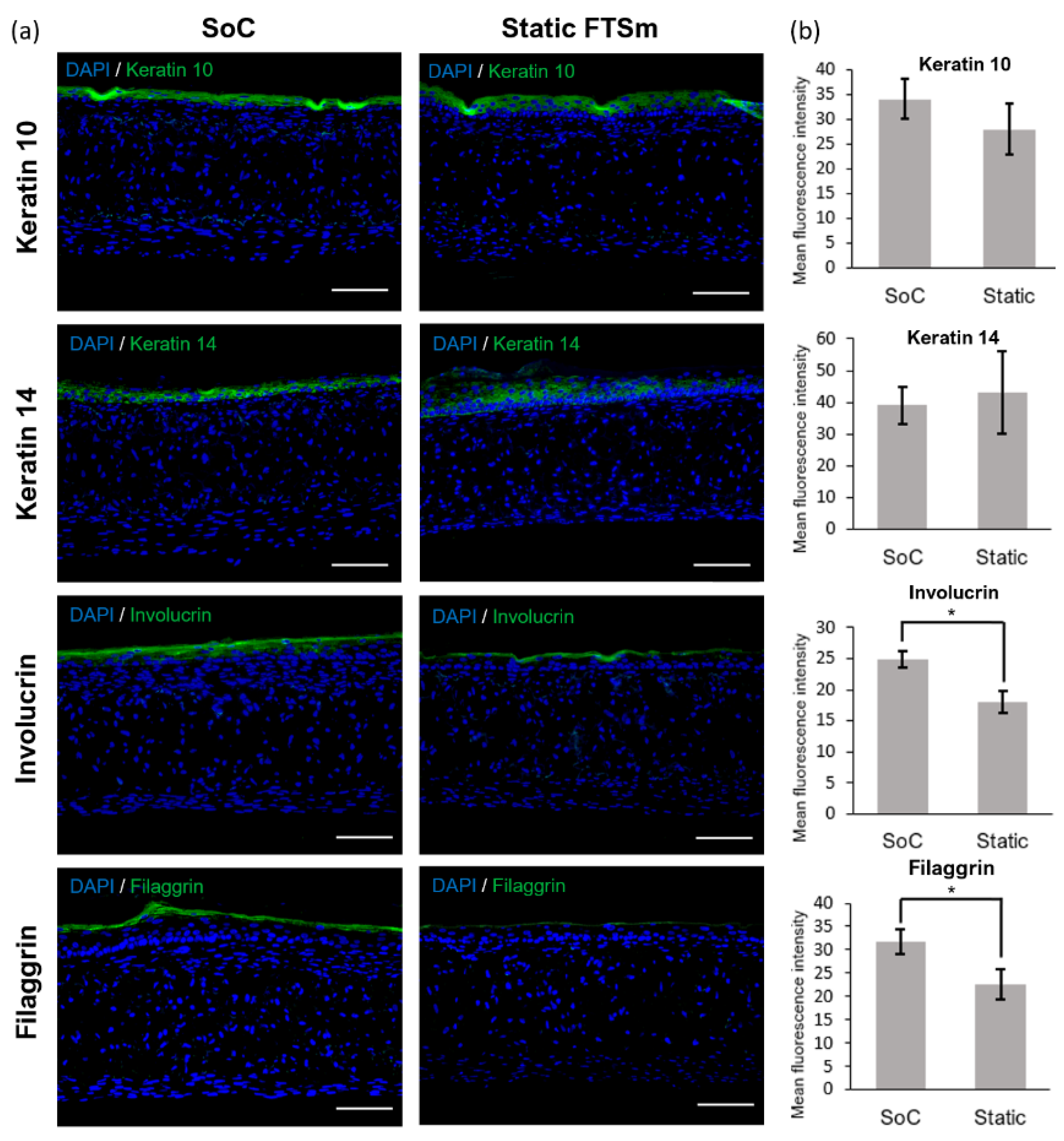
Finally, protein biomarkers representing key components of the epidermal compartment were assessed by immunofluorescence analysis (Figure 7a,b). HEKns at the basal layer express keratin 14, and, as they undergo a basal-to-suprabasal switch from keratin 14 to keratin 10, they move towards the surface and differentiate into the stratum spinosum. For both SoC and static models, the keratin 14 expression was localized mainly in the basal cell layer, and keratin 10 was expressed in the living suprabasal cell layers. Terminal differentiation markers, filaggrin, and involucrin showed an increased expression and a more continuous distribution in the upper layers of the SoC’s epidermis. This points to the more differentiated nature of the SoC model compared to the static FTSm.
3.4. SoC Produces Skin with Increased Barrier Properties
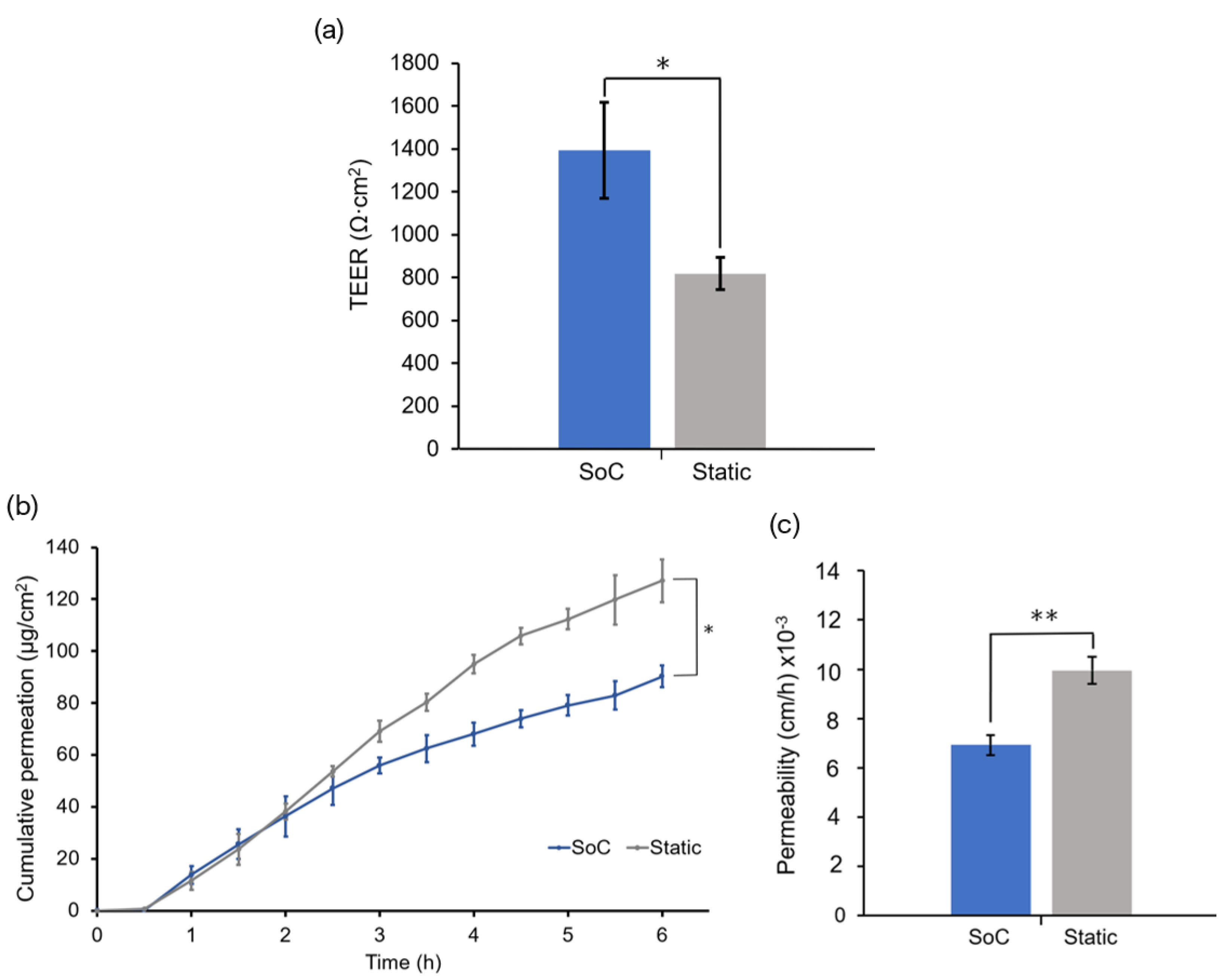
TEER was measured using the SoC with integrated tetrapolar electrodes to quantitively evaluate the skin barrier function. The barrier function of the FTSms developed on-chip (SoC) was compared with models grown off-chip (static) (Figure 8a). FTSms with TEER values ≤ 500 Ω·cm2 were considered damaged/defective and excluded from the study. The SoC model presents a significantly higher mean TEER than the static control. This value was 1393 ± 255 Ω·cm2 for the SoC models and 788 ± 78 Ω·cm2 for the controls (N = 3).
Figure 8b shows the cumulative amount of the FITC-dextran with molecular weight 4 KDa permeated through the FTSms developed on chip (SoC) and developed off-chip (static), using the seeding/drug testing module. The lag time to steady-state was similar between the different models. The SoC models presented significantly lower mean FITC-dextran cumulative amounts at 6h (90 ± 4 µg/cm2) as compared to the controls (127 ± 8 µg/cm2). The steady-state flux was calculated from the slope of the linear portion of the cumulative amount, and the permeability coefficient was calculated according to Fick’s first diffusion law (Figure 8c). The permeability coefficient was significantly lower for SoCs as compared to the controls.
4. Discussion
In this study, we present an SoC device to develop a full-thickness and fully human skin construct. The device includes a flexible architecture based on a modular and reusable approach. Conventional OoC are irreversibly sealed, usually through plasma bonding, making it difficult to completely remove the tissue for analysis [28]. The reversible-sealing feature allows easy removal of the skin tissue for histological and immunohistochemistry analysis without damaging the tissue and direct cell seeding. Furthermore, the device is fabricated using rapid prototyping and excludes soft-lithography and plasma bonding, making it compatible with mass production [29]. Importantly, the described design made it possible to integrate a thick scaffold (200 µm) for in vivo-like 3D cell culture generation of the dermal compartment.
One of the major challenges for generating a biomimetic skin model is the development of a dermal compartment with in vivo-like composition and mechanical environment while assuring its stability and reproducibility during culture and testing [30]. Typical FTSm generated inside an OoC device uses animal-derived hydrogels to recreate the dermal compartment [23,24,31,32,33,34,35]. These constructs are not fully representative of the in vivo ECM, which comprises multiple types of collagens, fibrous proteins, and proteoglycans but suffer from fibroblast-mediated contraction and matrix degradation, limiting their lifespan, reproducibility, and applicability [36]. In particular, the collagen detachment inside the SoC platform leads to various documented problems, including the inability to maintain a leakage-free fluid-tissue-air barrier and the inability to perform permeation assays in situ [37,38]. For SoC applications, the materials used for the dermis construct should mimic the biophysical properties of the in vivo skin and remain stable during cell culture. This was achieved in previous studies by adding synthetic or natural polymers to the hydrogels, for example, by combining fibrinogen with PEG [25]. However, the rheological behaviour of hydrogels makes them difficult to be manipulated and introduced in OoC devices in a reproducible manner [39].
Here, we propose an alternative approach by combining an inert scaffold integrated on the chip with the concept of a fibroblast-derived matrix, in which the dermal cells are stimulated to produce their own endogenous ECM components (FDM). Our group previously optimized this technique for the culture of a pigmented FTSm, under static conditions [27]. We showed that the developed model could maintain its architecture and function for up to 50 days at ALI. In this study, we evaluate the impact of the dynamic flow on the development of a dermis construct and FTSm.
There is abundant evidence that mechanical forces are important for the architecture and physiology of multiple tissues such as the lung, bone, and vascular tissues [40]. Furthermore, studies showed the effect of interstitial flown on fibroblasts, especially regarding its alignment [41,42]. The histological analysis of the generated dermal compartment showed fibroblasts populate the scaffold and generate FDM proteins, giving rise to a mature in vivo-like dermal structure. Compared to the static culture, developing a dermal compartment using dynamic flow resulted in increased deposition of FDM (fibronectin and collagen type I) onto the scaffold structure. The effect of the dynamic flow on FDM deposition could be seen in the case of dermal compartments cultured for 6 days on-chip and in FTSm cultured for approximately 20 days on-chip. It can be hypothesized that this phenomenon results from increased interstitial flow on-chip. In a porous medium such as the dermal compartment, the pore walls impede the momentum transport of the fluid outside the individual pores. Consequently, shear stresses in the fluid are often negligible. However, the dynamic flow can increase the convection necessary for transporting nutrients through the interstitial space, mimicking important components of the microcirculation [43]. Future experiments should be performed to determine interstitial flow velocity using Darcy’s law which relates velocity to the pressure gradient and the hydraulic conductivity of the dermal compartment. The described dermis-on-a-chip could be a relevant stand-alone model to study in vivo-like FDM deposition and remodelling. The tissue development using a porous polymeric scaffold can overcome important limitations of current SoC models due to its mechanical stability and robustness. The biologic variability is reduced since this approach does not require exogenous animal-derived collagen hydrogels. Moreover, since no hydrogels are introduced in the model, the manipulation of the device could be easily performed in a reproducible manner with syringe/peristaltic pumps.
The mature dermal matrix was then used to recreate an FTSm with added perfusion. Conventional skin models still have important limitations, including increased permeability and different architecture than native human skin [44]. One proposed explanation is the lack of in vivo-like mechanical forces and dynamic flow under static conditions. Using the developed OoC platform, we generated a mature, pluristratified, and orthokeratinized epidermal construct with increased thickness and barrier function compared to the static models. The SoC models presented an organized cell morphology with basal keratinocytes undergoing sequential differentiation and stratification, forming keratinocytes with a morphology characteristic of the stratum spinosum and stratum granulosum. Finally, the keratinocytes underwent terminal differentiation into anuclear, flattened corneocytes within the stratum corneum layers, similar to the in vivo skin. Immunofluorescence analysis further showed the presence of markers of basal, suprabasal, and terminally differentiated cells expressed in the corresponding layers. Compared to the static model, the SoC showed increased filaggrin expression, a skin barrier protein and differentiation marker, and a trend for increased involucrin expression. This observation is similar to others reported in the literature [25,34].
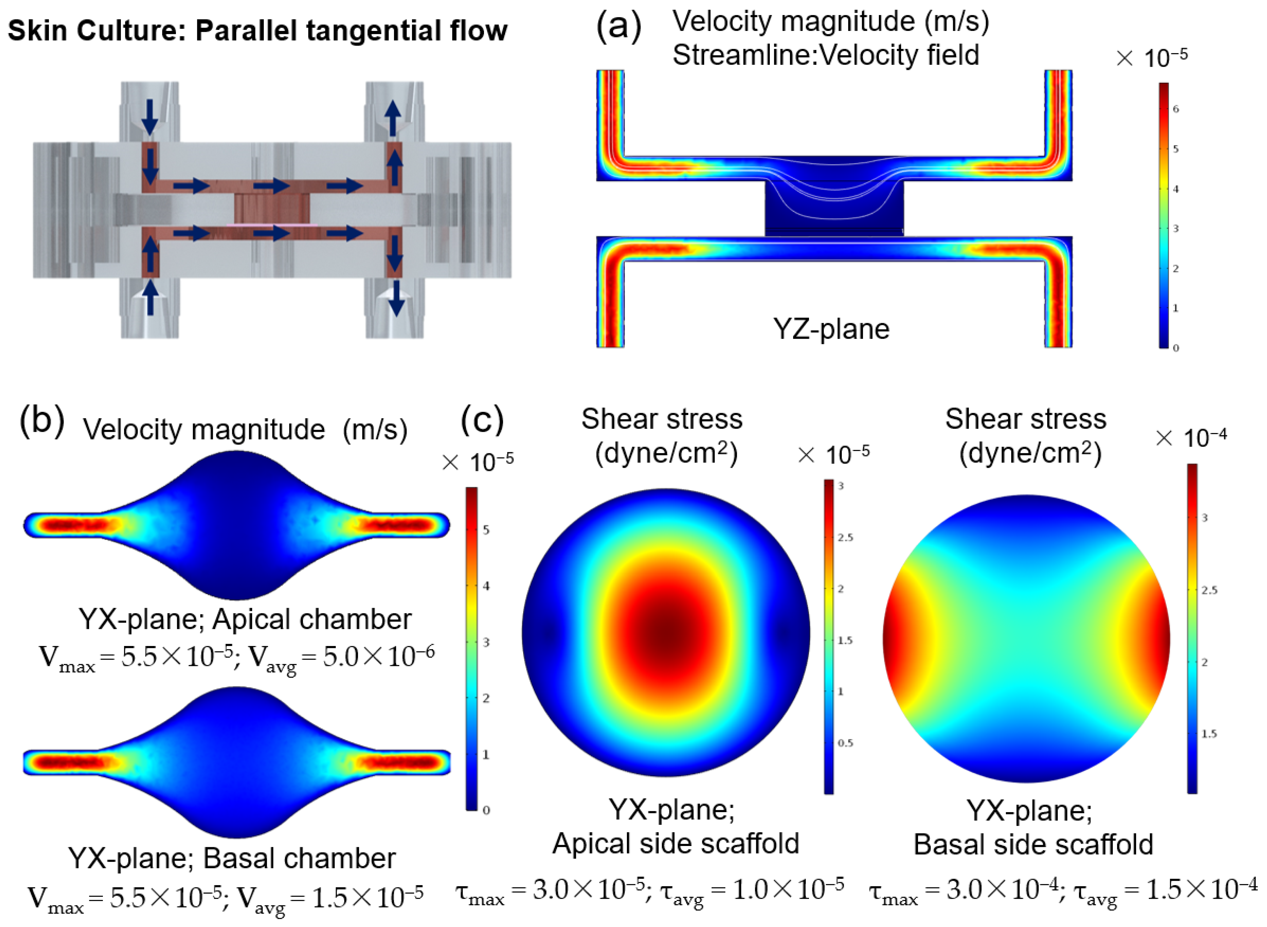
Shear stresses with a magnitude of 0.06 dyn/cm2 impact keratinocyte morphology leading to morphological variation and cytoskeletal reorganization, and a magnitude of 6 dyn/cm2 results in cellular disruption [45]. It has been hypothesized that shear stresses acting on the epidermal layer under submerged conditions could contribute to the positive effect of dynamic perfusion on skin constructs. To study this effect, simulations were performed to calculate the shear stress and to study the hydrodynamics of the SoC during the 48 h under submerged conditions, with double tangential perfusion. The overall chamber design protects the cells from the effects of the shear stress and, combined with small flow rates, results in low shear stress with a maximum magnitude of 3 × 10⁻⁵ dyn/cm2 at the centre of the apical chamber. These low values are not expected to significantly impact the cell morphology and behaviour. Thus, the particular role of shear stress for skin optimization seems to be reduced using the described device and protocol. It can be hypothesized that the differences between the SoC model and the controls result from the dynamic transport and interstitial flow inside the chip, which can enhance the transport of nutrients and induce various morphogenetic effects [43]. Furthermore, the peristaltic flow may induce mechanical stretching, generating a thicker epidermis [46].
It is relevant to note that, in this study, the static FTsm present lower thickness and lower filaggrin expression than the models generated in our previous studies using primary HEKns at a 3rd passage [27]. This is possibly a consequence of the higher keratinocyte passage (6th passage) used. Further studies should be performed to fully characterize the impact of the cell passage on skin differentiation.
The skin barrier function was also evaluated by performing TEER measurements. In a previous study, we showed that the OoC with integrated sensors could monitor the skin barrier in real-time, which is useful for following skin development and evaluating the toxicity of topical drugs [26]. In this study, we used TEER to compare the barrier of the SoC models with the static controls. The mean TEER of the skin tissues generated on-chip was significantly higher than those generated off-chip, without perfusion. This result correlates with the increased expression of filaggrin and involucrin in SoC models, both proteins that contribute to the integrity of the epidermal barrier. The increased SoC barrier function could also be seen by its significantly lower FITC-dextran permeability when compared to the controls. The permeation studies could be performed directly on-chip using the drug testing module, avoiding Franz diffusion cell experiments. The non-contractile nature of the developed dermal compartment avoided common artifacts reported in the literature, such as incorrect sealing compromising the permeation results [34].
5. Conclusions
We have developed a 3D full-thickness SoC model based on a fibroblast-derived matrix. The platform has a modular and reversible sealing approach, resulting in a flexible architecture that allows the leakage-free integration of a porous scaffold. Furthermore, it offers the advantages of performing downstream assays such as toxicity and permeation tests in situ. Interchangeable modules were developed to suit specific tests/applications. With the proposed platform, human fibroblasts are stimulated to produce their extracellular matrix, which deposits onto the scaffold structure, resulting in a fully human dermal compartment. Its non-contractile nature increased the stability of the construct and avoided the artifacts observed in conventional collagen-based structures. Dynamic flow applied during dermis generation replicated the effects of interstitial flow and increased FDM deposition. Controlled perfusion and airflow resulted in a full-thickness human skin model with in vivo-like characteristics, including a well-differentiated and organized epidermis with increased thickness and enhanced barrier function. The integrated TEER sensors gave a means of quality control, offering a non-destructive real-time tool to study the skin barrier function. In the future, additional cell types such as melanocytes, immune and endothelial cells could be integrated into the current SoC model to expand its applicability. Additionally, the use of induced pluripotent stem cells (iPSCs) could be explored as a tool for personalized medicine to model healthy and disease characteristics.
Author Contributions
Conceptualization, P.Z. and A.O.; methodology, P.Z.; software, P.Z.; validation, P.Z.; formal analysis, P.Z.; investigation, P.Z. and S.L.-V.; resources, A.O., P.Z. and S.L.-V.; data curation, P.Z.; writing—original draft preparation, P.Z.; writing—review and editing, P.Z., A.O. and S.L.-V.; visualization, P.Z.; supervision, A.O.; project administration, A.O.; funding acquisition, A.O. All authors have read and agreed to the published version of the manuscript.
Funding
This research was funded by Fundação para a Ciência e Tecnologia by UID/Multi/04462/2013 and PD/BD/128164/2016.
Institutional Review Board Statement
This study only included commercially available cells. It was approved by the iNOVA4Heath platform (UID/ Multi/04462/2013) and followed the ethical research rules of the NOVA University of Lisbon.
Informed Consent Statement
Not applicable.
Data Availability Statement
The data that support the findings of this study are available from the corresponding author, upon reasonable request.
Acknowledgments
NOVA4Health—UID/Multi/04462/2013, a program financially supported by Fundação para a Ciência e Tecnologia/ Ministério da Educação e Ciência, through national funds and co-funded by FEDER under the PT2020 Partnership Agreement, is acknowledged. PZ acknowledges PD/BD/128164/2016 for the Ph.D. fellowship funded by FCT, Portugal.
Conflicts of Interest
The authors declare no conflict of interest.
Appendix A
Figure A1.
Schematic design including an exploded view (top) and cut (bottom) of the (a) SoC device with integrated TEER sensors made of Ag/AgCl-sintered pellet electrode, insulating polyether ether ketone (PEEK) tubing and external silver tubing, and (b) Module for drug testing/cell seeding with a central open reservoir, integrated O-ring and basal chamber for perfusion. The modular design and reversible sealing allow the modules to be easily exchanged without causing disruption and/or damage to the cell culture layer.

Figure A2.
Finite element analysis to study the hydrodynamic of the skin-on-a-chip platform during submerged conditions with apical and basal side perfusion (double tangential perfusion). (a) streamlines and magnitude of velocity through the centre of the chamber on the y,z plane. (b) velocity magnitude at the apical and basal chamber on the y,z plane. (c) magnitude of the shear stress at the cell surface on the x,y plane at the apical and basal sides of the scaffold.

References
- Seth, D.; Cheldize, K.; Brown, D.; Freeman, E.F. Global Burden of Skin Disease: Inequities and Innovations. Curr. Dermatol. Rep. 2017, 6, 204–210. [Google Scholar] [CrossRef] [PubMed]
- Wang, W.; Lu, K.J.; Yu, C.H.; Huang, Q.L.; Du, Y.Z. Nano-drug delivery systems in wound treatment and skin regeneration. J. Nanobiotechnol. 2019, 17, 82. [Google Scholar] [CrossRef] [PubMed]
- Almeida, A.; Sarmento, B.; Rodrigues, F. Insights on in vitro models for safety and toxicity assessment of cosmetic ingredients. Int. J. Pharm. 2017, 519, 178–185. [Google Scholar] [CrossRef] [PubMed]
- Zuang, V.; Desprez, B.; Barroso, J.; Belz, S.; Berggren, E.; Bernasconi, C.; Bessems, J.; Bopp, S.; Casati, S.; Coecke, S.; et al. EURL ECVAM Status Report on the Development, Validation and Regulatory Acceptance of Alternative Methods and Approaches (2015) EURL ECVAM Status Report 2015; European Comission: Bruxelles, Belgium, 2015; ISBN 978-92-79-51989-5. [Google Scholar]
- Van Norman, G.A. Limitations of Animal Studies for Predicting Toxicity in Clinical Trials: Is it Time to Rethink Our Current Approach? JACC Basic Transl. Sci. 2019, 4, 845–854. [Google Scholar] [CrossRef] [PubMed]
- Avci, P.; Sadasivam, M.; Gupta, A.; De Melo, W.C.M.A.; Huang, Y.-Y.; Yin, R.; Chandran, R.; Kumar, R.; Otufowora, A.; Nyame, T.; et al. Animal models of skin disease for drug discovery. Expert Opin. Drug Discov. 2013, 8, 331–355. [Google Scholar] [CrossRef] [PubMed] [Green Version]
- Seok, J.; Shaw Warren, H.; Alex, G.C.; Michael, N.M.; Henry, V.B.; Xu, W.; Richards, D.R.; McDonald-Smith, G.P.; Gao, H.; Hennessy, L.; et al. Genomic responses in mouse models poorly mimic human inflammatory diseases. Proc. Natl. Acad. Sci. USA 2013, 110, 3507–3512. [Google Scholar] [CrossRef] [PubMed] [Green Version]
- Mathes, S.H.; Ruffner, H.; Graf-Hausner, U. The use of skin models in drug development. Adv. Drug Deliv. Rev. 2014, 69, 81–102. [Google Scholar] [CrossRef]
- Hewitt, N.J.; Edwards, R.J.; Fritsche, E.; Goebel, C.; Aeby, P.; Scheel, J.; Reisinger, K.; Ouédraogo, G.; Duche, D.; Eilstein, J.; et al. Use of human in Vitro skin models for accurate and ethical risk assessment: Metabolic considerations. Toxicol. Sci. 2013, 133, 209–217. [Google Scholar] [CrossRef] [PubMed] [Green Version]
- Astashkina, A.; Grainger, D.W. Critical analysis of 3-D organoid in vitro cell culture models for high-throughput drug candidate toxicity assessments. Adv. Drug Deliv. Rev. 2014, 69, 1–18. [Google Scholar] [CrossRef]
- Poumay, Y.; Coquette, A. Modelling the human epidermis in vitro: Tools for basic and applied research. Arch. Dermatol. Res. 2007, 298, 361–369. [Google Scholar] [CrossRef] [Green Version]
- Wu, Q.; Liu, J.; Wang, X.; Feng, L.; Wu, J.; Zhu, X.; Wen, W.; Gong, X. Organ-on-a-chip: Recent breakthroughs and future prospects. Biomed. Eng. Online 2020, 19, 1–19. [Google Scholar] [CrossRef] [PubMed] [Green Version]
- Clarke, G.A.; Hartse, B.X.; Asli, A.E.N.; Taghavimehr, M.; Hashemi, N.; Shirsavar, M.A.; Montazami, R.; Alimoradi, N.; Nasirian, V.; Ouedraogo, L.J.; et al. Advancement of sensor integrated organ-on-chip devices. Sensors 2021, 21, 1367. [Google Scholar] [CrossRef] [PubMed]
- Ataç, B.; Wagner, I.; Horland, R.; Lauster, R.; Marx, U.; Tonevitsky, A.G.; Azar, R.P.; Lindner, G. Skin and hair on-a-chip: In vitro skin models versus ex vivo tissue maintenance with dynamic perfusion. Lab Chip 2013, 13, 3555–3561. [Google Scholar] [CrossRef] [PubMed] [Green Version]
- Abaci, H.E.; Gledhill, K.; Guo, Z.; Christiano, A.M.; Shuler, M.L. Pumpless microfluidic platform for drug testing on human skin equivalents. Lab Chip 2015, 15, 882–888. [Google Scholar] [CrossRef] [PubMed] [Green Version]
- Kim, J.J.; Ellett, F.; Thomas, C.N.; Jalali, F.; Anderson, R.R.; Irimia, D.; Raff, A.B. A microscale, full-thickness, human skin on a chip assay simulating neutrophil responses to skin infection and antibiotic treatments. Lab Chip 2019, 19, 3094–3103. [Google Scholar] [CrossRef] [PubMed]
- Alexander, F.A.; Eggert, S.; Wiest, J. Skin-on-a-chip: Transepithelial electrical resistance and extracellular acidification measurements through an automated air-liquid interface. Genes 2018, 9, 114. [Google Scholar] [CrossRef] [PubMed] [Green Version]
- Wagner, I.; Materne, E.M.; Brincker, S.; Süßbier, U.; Frädrich, C.; Busek, M.; Sonntag, F.; Sakharov, D.A.; Trushkin, E.V.; Tonevitsky, A.G.; et al. A dynamic multi-organ-chip for long-term cultivation and substance testing proven by 3D human liver and skin tissue co-culture. Lab Chip 2013, 13, 3538–3547. [Google Scholar] [CrossRef] [Green Version]
- Maschmeyer, I.; Lorenz, A.K.; Schimek, K.; Hasenberg, T.; Ramme, A.P.; Hübner, J.; Lindner, M.; Drewell, C.; Bauer, S.; Thomas, A.; et al. A four-organ-chip for interconnected long-term co-culture of human intestine, liver, skin and kidney equivalents. Lab Chip 2015, 15, 2688–2699. [Google Scholar] [CrossRef] [Green Version]
- Kühnl, J.; Tao, T.P.; Brandmair, K.; Gerlach, S.; Rings, T.; Müller-Vieira, U.; Przibilla, J.; Genies, C.; Jaques-Jamin, C.; Schepky, A.; et al. Characterization of application scenario-dependent pharmacokinetics and pharmacodynamic properties of permethrin and hyperforin in a dynamic skin and liver multi-organ-chip model. Toxicology 2021, 448, 152687. [Google Scholar] [CrossRef]
- Wufuer, M.; Lee, G.H.; Hur, W.; Jeon, B.; Kim, B.J.; Choi, T.H.; Lee, S.H. Skin-on-a-chip model simulating inflammation, edema and drug-based treatment. Sci. Rep. 2016, 6, 37471. [Google Scholar] [CrossRef] [Green Version]
- Ramadan, Q.; Ting, F.C.W. In vitro micro-physiological immune-competent model of the human skin. Lab Chip 2016, 16, 1899–1908. [Google Scholar] [CrossRef] [PubMed]
- Mori, N.; Morimoto, Y.; Takeuchi, S. Skin integrated with perfusable vascular channels on a chip. Biomaterials 2017, 116, 48–56. [Google Scholar] [CrossRef] [PubMed]
- Lee, S.; Jin, S.P.; Kim, Y.K.; Sung, G.Y.; Chung, J.H.; Sung, J.H. Construction of 3D multicellular microfluidic chip for an in vitro skin model. Biomed. Microdevices 2017, 19, 1–14. [Google Scholar] [CrossRef] [PubMed]
- Sriram, G.; Alberti, M.; Dancik, Y.; Wu, B.; Wu, R.; Feng, Z.; Ramasamy, S.; Bigliardi, P.L.; Bigliardi-Qi, M.; Wang, Z. Full-thickness human skin-on-chip with enhanced epidermal morphogenesis and barrier function. Mater. Today 2018, 21, 326–340. [Google Scholar] [CrossRef]
- Zoio, P.; Lopes-ventura, S.; Oliva, A. Barrier-on-a-chip with a modular architecture and integrated sensors for real-time measurement of biological barrier function. Micromachines 2021, 12, 816. [Google Scholar] [CrossRef] [PubMed]
- Zoio, P.; Ventura, S.; Leite, M.; Oliva, A. Pigmented full-thickness human skin model based on a fibroblast-derived matrix for long-term studies. Tissue Eng. Part C Methods 2021, 27, 433–443. [Google Scholar] [CrossRef] [PubMed]
- Temiz, Y.; Lovchik, R.D.; Kaigala, G.V.; Delamarche, E. Lab-on-a-chip devices: How to close and plug the lab? Microelectron. Eng. 2015, 132, 156–175. [Google Scholar] [CrossRef]
- Schneider, S.; Gruner, D.; Richter, A.; Loskill, P. Membrane integration into PDMS-free microfluidic platforms for organ-on-chip and analytical chemistry applications. Lab Chip 2021, 21, 1866–1885. [Google Scholar] [CrossRef] [PubMed]
- Risueño, I.; Valencia, L.; Jorcano, J.L. Skin-on-a-chip models: General overview and future perspectives. APL Bioeng. 2021, 5, 030901. [Google Scholar] [CrossRef] [PubMed]
- Abaci, H.E.; Guo, Z.; Coffman, A.; Gillette, B.; Lee, W.H.; Sia, S.K.; Christiano, A.M. Human Skin Constructs with Spatially Controlled Vasculature Using Primary and iPSC-Derived Endothelial Cells. Adv. Healthc. Mater. 2016, 5, 1800–1807. [Google Scholar] [CrossRef] [PubMed] [Green Version]
- Kim, B.S.; Gao, G.; Kim, J.Y.; Cho, D.W. 3D Cell Printing of Perfusable Vascularized Human Skin Equivalent Composed of Epidermis, Dermis, and Hypodermis for Better Structural Recapitulation of Native Skin. Adv. Healthc. Mater. 2019, 8, e1801019. [Google Scholar] [CrossRef] [PubMed]
- Song, H.J.; Lim, H.Y.; Chun, W.; Choi, K.C.; Lee, T.Y.; Sung, J.H.; Sung, G.Y. Development of 3D skin-equivalent in a pump-less microfluidic chip. J. Ind. Eng. Chem. 2018, 60, 355–359. [Google Scholar] [CrossRef]
- Strüver, K.; Friess, W.; Hedtrich, S. Development of a Perfusion Platform for Dynamic Cultivation of in vitro Skin Models. Skin Pharmacol. Physiol. 2017, 30, 180–189. [Google Scholar] [CrossRef] [PubMed]
- Schimek, K.; Hsu, H.H.; Boehme, M.; Kornet, J.J.; Marx, U.; Lauster, R.; Pörtner, R.; Lindner, G. Bioengineering of a full-thickness skin equivalent in a 96-well insert format for substance permeation studies and organ-on-a-chip applications. Bioengineering 2018, 5, 43. [Google Scholar] [CrossRef] [PubMed] [Green Version]
- Frantz, C.; Stewart, K.M.; Weaver, V.M. The extracellular matrix at a glance. J. Cell Sci. 2010, 123, 4195–4200. [Google Scholar] [CrossRef] [PubMed] [Green Version]
- Gee, C.M.; Watkinson, A.C.; Nicolazzo, J.A.; Finnin, B.C. The Effect of Formulation Excipients on the Penetration and Lateral Diffusion of Ibuprofen on and within the Stratum Corneum Following Topical Application to Humans. J. Pharm. Sci. 2014, 103, 909–919. [Google Scholar] [CrossRef] [PubMed]
- Zhang, Q.; Saad, P.; Mao, G.; Walters, R.M.; Mack Correa, M.C.; Mendelsohn, R.; Flach, C.R. Infrared Spectroscopic Imaging Tracks Lateral Distribution in Human Stratum Corneum. Pharm. Res. 2014, 31, 2762–2773. [Google Scholar] [CrossRef] [PubMed]
- Valencia, L.; Tejero, V.C.; Clemente, M.; Fernaud, I.; Holgado, M. OPEN A new microfluidic method enabling the generation of multi-layered tissues—on—chips using skin cells as a proof of concept. Sci. Rep. 2021, 11, 13160. [Google Scholar] [CrossRef] [PubMed]
- Ogawa, R. Chapter 9—Mechanobiology and Mechanotherapy in Tissue Engineering. In In Situ Tissue Regeneration: Host Cell Recruitment and Biomaterial Design; Lee, S.J., Yoo, J.J., Atala, A.B.T.-I.S.T.R., Eds.; Academic Press: Boston, MA, USA, 2016; pp. 165–181. ISBN 978-0-12-802225-2. [Google Scholar]
- Ng, C.P.; Swartz, M.A. Fibroblast alignment under interstitial fluid flow using a novel 3-D tissue culture model. Am. J. Physiol. Circ. Physiol. 2003, 284, H1771–H1777. [Google Scholar] [CrossRef]
- Ng, C.P.; Swartz, M.A. Mechanisms of Interstitial Flow-Induced Remodeling of Fibroblast–Collagen Cultures. Ann. Biomed. Eng. 2006, 34, 446–454. [Google Scholar] [CrossRef] [Green Version]
- Swartz, M.A.; Fleury, M.E. Interstitial Flow and Its Effects in Soft Tissues. Annu. Rev. Biomed. Eng. 2007, 9, 229–256. [Google Scholar] [CrossRef] [PubMed] [Green Version]
- Mohammadi, M.H.; Heidary Araghi, B.; Beydaghi, V.; Geraili, A.; Moradi, F.; Jafari, P.; Janmaleki, M.; Valente, K.P.; Akbari, M.; Sanati-Nezhad, A. Skin Diseases Modeling using Combined Tissue Engineering and Microfluidic Technologies. Adv. Healthc. Mater. 2016, 5, 2459–2480. [Google Scholar] [CrossRef] [PubMed]
- Agarwal, T.; Narayana, G.H.; Banerjee, I. Keratinocytes are mechanoresponsive to the microflow-induced shear stress. Cytoskeleton 2019, 76, 209–218. [Google Scholar] [CrossRef] [PubMed]
- Tokuyama, E.; Nagai, Y.; Takahashi, K.; Kimata, Y.; Naruse, K. Mechanical stretch on human skin equivalents increases the epidermal thickness and develops the basement membrane. PLoS ONE 2015, 10, e0141989. [Google Scholar] [CrossRef] [PubMed] [Green Version]
Figure 1.
Skin-on-a-chip (SoC) device with modular architecture (a) Schematic representation of closed device with blue dye showing the apical and basal chamber (b) Exploded view of the SoC platform. The device consists of a central insert for cell culture and two external compartments made of polycarbonate for top and bottom perfusion with air and/or medium. The central insert layer is composed of polydimethylsiloxane (PDMS) and includes a porous polystyrene scaffold. (c) Photograph of the SoC with blue dye used to distinguish the apical and basal compartments. (d) Photograph of the cell culture layer with a central porous scaffold sandwiched between a PDMS layer and a PCR tape. (e) Two assembled devices placed in a dedicated platform. SoC on the left is sealed using only the magnetic latching, and the SoC on the right is sealed using magnets and screws.

Figure 2.
Schematic representation of a cross-sectional view of the device (blue rectangle) showing the main steps implemented for generation of a full-thickness skin model based on a fibroblast-derived matrix: (a–c) the development of a mature dermis, (d,e) the culture of epidermal cells under submerged conditions with double perfusion and (f) the culture of the epidermis at the air-liquid interface until a fully differentiated skin is generated. (g,h) After 11 days, a stratified epidermis on top of a mature dermis is obtained, and in vitro testing can be performed on-chip.

Figure 3.
Impact of the dermis maturation and FDM protein production on the support and development of a full-thickness skin model. Representative H&E micrographs of full-thickness skin equivalents (a) generated with less developed and mature dermal compartments by seeding 5 × 10⁶ cells/mL, showing keratinocyte infiltration (black arrows), (b) generated with a mature dermal compartment by seeding 20 × 106 cells/mL, showing excessive FDM deposition (red arrows) at the apical side and (c) deposition at the basal side. Scale bares: 100 µm. (d) Photograph of the device basal chamber showing extracellular matrix deposited on the fluidic network and clogging the inlets/outlets (blue arrows).

Figure 4.
Impact of the dynamic flow on the generation of a dermal equivalent based on a fibroblast-derived matrix after 6 days of culture. (a) Representative H&E images dermal model cultured using dynamic flow (single tangential flow) and static conditions (control). (b) Representative immunofluorescence analysis showing ECM proteins (collagen type I and fibronectin) deposited onto the dermal models. Nuclei are stained with DAPI (blue). Images on the top and bottom are the same samples with different magnifications. Scale bares: 100 µm. (c) Mean fluorescence intensity for collagen I and fibronectin. Error bars represent mean ± SD. * and ** indicate statistically significant differences with p < 0.05 and p < 0.01, respectively.

Figure 5.
Epidermal morphogenesis in full-thickness skin-on-a-chip (SoC) models and full-thickness skin models grown under static conditions (Static FTSm), grown for 11 days at the air-liquid interface (ALI). Representative H&E micrographs for 2 repetitions, showing thicker viable epidermis in the SoC model. For both models, the images show the zones of maximum thickness from the available samples. Scale bars: 100 μm.

Figure 6.
Immunofluorescence analysis of full-thickness skin-on-a-chip (SoC) model and full-thickness skin model (FTSm) grown under static conditions. The models were generated by culturing the dermal compartment for 6 days, allowing epidermal differentiation for 11 days at the air-liquid interface (ALI). (a) Representative immunofluorescence images of ECM proteins most often found in the dermis (collagen I and fibronectin). Nuclei are stained with DAPI (blue). Scale bars: 100 μm. (b) Mean fluorescence intensity for collagen I and fibronectin. Error bars represent mean ± SD. * indicate statistically significant differences with p < 0.05, respectively.

Figure 7.
Immunofluorescence analysis of full-thickness skin-on-a-chip (SoC) model and full-thickness skin model (FTSm) grown under static conditions. The models were generated by culturing the dermal compartment for 6 days, allowing epidermal differentiation for 11 days at the air-liquid interface (ALI). (a) Representative immunofluorescence images of proteins typically associated with epidermal differentiation (keratin 10, keratin 14, involucrin, and filaggrin). Nuclei are stained with DAPI (blue). Scale bars: 100 µm. (b) Mean fluorescence intensity for keratin 10, keratin 14, involycrin, and filaggrin. Error bars represent mean ± SD. * indicate statistically significant differences with p < 0.05.

Figure 8.
Comparison of the skin barrier function between skin-on-a-chip (SoC) models and static models (a) trans-epithelial electrical resistance (TEER) measurements measured using concentric Ag/AgCl electrodes and an EVOM system. The measurements were performed after 11 days of culture at the air/liquid interface by filling the apical and donor compartment with PBS (N = 3 and 2 technical replicates (n = 2) for SoCs and N = 3 and different technical replicates: n = 3,2,3 for the static models). Models with TEER values ≤ 500 Ωcm2 were excluded from the study. (b) cumulative permeation of FITC-dextran in SoC (N = 3, n = 1) and static control models (N = 3, n = 2). (c) permeability coefficient in SoC models and controls. Permeation testing was performed on tissue models generated for 11 days at the air/liquid interface using the cell seeding/drug testing module. Error bars represent mean ± SD. * and ** indicate statistically significant differences with p < 0.05 and p < 0.01, respectively.

Publisher’s Note: MDPI stays neutral with regard to jurisdictional claims in published maps and institutional affiliations. |
© 2022 by the authors. Licensee MDPI, Basel, Switzerland. This article is an open access article distributed under the terms and conditions of the Creative Commons Attribution (CC BY) license (https://creativecommons.org/licenses/by/4.0/).
Share and Cite
MDPI and ACS Style
Zoio, P.; Lopes-Ventura, S.; Oliva, A. Biomimetic Full-Thickness Skin-on-a-Chip Based on a Fibroblast-Derived Matrix. Micro 2022, 2, 191-211. https://0-doi-org.brum.beds.ac.uk/10.3390/micro2010013
AMA Style
Zoio P, Lopes-Ventura S, Oliva A. Biomimetic Full-Thickness Skin-on-a-Chip Based on a Fibroblast-Derived Matrix. Micro. 2022; 2(1):191-211. https://0-doi-org.brum.beds.ac.uk/10.3390/micro2010013
Chicago/Turabian StyleZoio, Patrícia, Sara Lopes-Ventura, and Abel Oliva. 2022. "Biomimetic Full-Thickness Skin-on-a-Chip Based on a Fibroblast-Derived Matrix" Micro 2, no. 1: 191-211. https://0-doi-org.brum.beds.ac.uk/10.3390/micro2010013