Fabrication of Irregularity-Free, Highly Circular Cross-Sectional Microchannel


Department of Mechanical Engineering, Tokyo Institute of Technology, Kanagawa 226-8502, Japan
*
Author to whom correspondence should be addressed.
Micro 2022, 2(2), 325-333; https://0-doi-org.brum.beds.ac.uk/10.3390/micro2020021
Submission received: 12 April 2022
/
Revised: 18 May 2022
/
Accepted: 22 May 2022
/
Published: 24 May 2022
(This article belongs to the Section Microscale Engineering)
Abstract
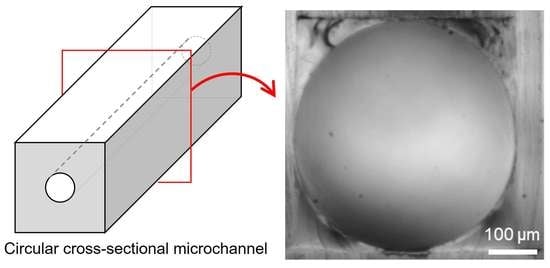
:Microchannels typically have rectangular cross-sections, whereas biological channels, such as blood vessels and airways, have circular cross-sections. The difference in cross-sections causes different fluidic behaviors, resulting in differences between fluidic behavior in microchannels and biological channels. To simulate fluidic behavior in vitro, circular cross-sectional microchannels are required. We developed a circular cross-sectional microchannel with a smooth channel wall, free from cracks and irregularities. In the fabrication process of the circular cross-sectional microchannel, uncured polydimethylsiloxane (PDMS) was inserted into a rectangular cross-sectional microchannel. Then, the PDMS was pushed out by the introduction of compressed air before the curing process. During the introduction of compressed air, we observed the behavior of the uncured PDMS and found the formation and movement of protrusions along the microchannel. After pushing out the uncured PDMS, the residual PDMS was cured, resulting in a circular cross-sectional microchannel. The fabrication method was examined by varying the channel orientation and airflow direction. In the case of the horizontal orientation and airflow in an opposite direction, the circularity of the microchannel was greater than 0.99 at the centimeter scale in all cross-sections along the microchannel.
1. Introduction
Microfluidic technologies have been developed based on the advances in microfabrication, resulting in advances in the microscale fields of chemistry [1,2], biology [3,4], and medicine [5,6]. They have attracted the attention of numerous researchers in these fields for the development of biological and medical applications. For example, the behaviors [7] and deformations [8] of red blood cells flowing through a single micrometer cross-sectional microchannel have been visualized, and the degradation of their cellular membranes due to the change in oxygen tension driven by flow has been found [9]. The behavior of cancer cells has been measured under a gradient of oxygen tension and glucose concentration [10,11]. For these studies, microfluidic devices made using the conventional fabrication method of soft lithography have been used. This uses a photo-patterned mold and polydimethylsiloxane (PDMS), resulting in rectangular cross-sectional microchannels [12]. However, the cross-sections of biological channels, such as blood vessels, lymphatic vessels, intestinal channels, airways, and periarterial spaces [13] are almost circular. This is because of the minimization of fluidic resistance by minimizing the perimeter under a constant cross-sectional area of the microchannels, resulting in a circular cross-section [14]. The difference in cross-sectional shapes influences the behavior of cells flowing through them, for example, deformation and damage to cells [15], inertia focusing [16], and platelet adhesion and aggregation [17] inside the microchannels. To reproduce the behavior of cells in such biological channels in vitro, the cross-section of the microchannels should be circular.
Methods for fabricating circular cross-sectional microchannels have been developed. The fabrication method using a femtosecond laser has achieved a circular cross-section of high circularity; however, its size is limited because it uses the nanofabrication technique [18,19]. A fabrication method that combines two microchannels of a semi-circular cross-section has been developed [20,21]. It requires a highly precise alignment directly before bonding. A fabrication method was developed by introducing air into the PDMS-filled microchannel of a rectangular cross-section after the curing process [22]. It achieved a circular cross section; however, the circularity was not constant and cracks existed. The geometrical irregularities of microchannels have made the reproduction of in vivo biological phenomena difficult in vitro.
Here, we improve the fabrication method by introducing air and changing the cured PDMS into uncured PDMS in a rectangular cross-sectional microchannel. Uncured PDMS is a viscous fluid, and the shape of the microchannel before the curing process is dynamically changed by the airflow. This is followed by a necessary stabilization process. To verify the circularity and irregularity, we used a centimeter-order microchannel. The airflow and gravity directions were adjusted and a highly circular cross-sectional microchannel without irregularities such as cracks and dumps was achieved.
2. Fabrication of Circular Cross-Sectional Microchannel
2.1. Working Principle
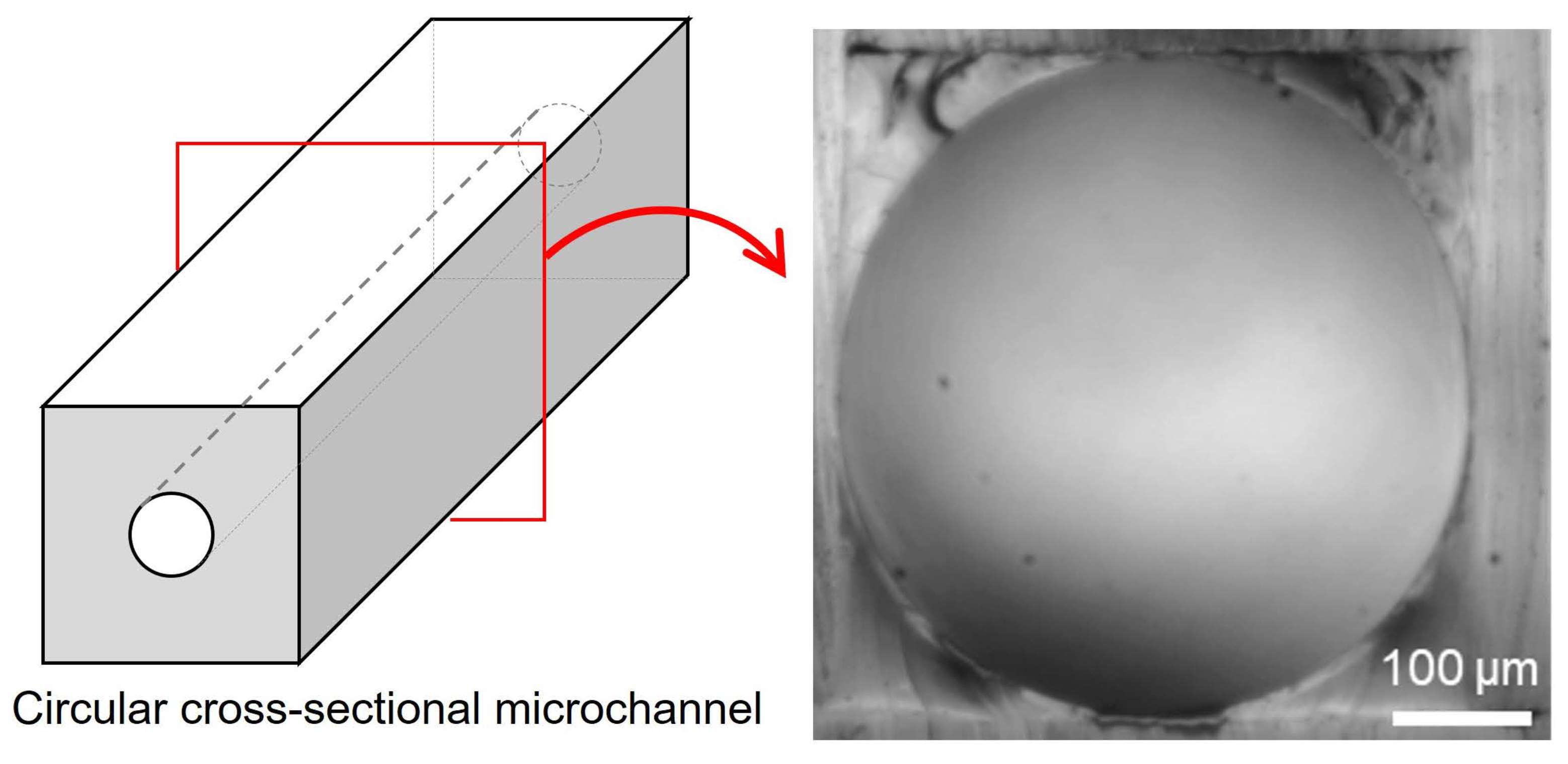
A liquid is typically attached on a solid surface, except for a hydrophobic surface, to minimize the surface free energy. When the solid surface has microscaled steps, the liquid sticks along the corners of the steps, resulting in a smooth surface. This is caused by the surface tension of the liquid. This also occurs in microchannels. The corners of a rectangular cross-section of a microchannel can be smoothed by residual liquid after pushing out liquid from the microchannels by the introduction of a gas (Figure 1). When the liquid is PDMS, the corners are filled with the PDMS. Circular cross-sectional microchannels can be obtained by heating the microchannel with the residual PDMS at the corners. Moreover, to obtain smooth surfaces along the microchannel, the formation of protrusions can be prevented by utilizing long-term airflow to stabilize the surface geometry. With this process, the roughness on the surface of the microchannel decreases, resulting in smooth surfaces.
2.2. Design of Microchannel
A rectangular cross-sectional microchannel was designed as a base to form a circular cross section. The shape was a simple straight channel. The original square cross-section was 500 μm high, 500 μm wide, and 2 cm long. It was made of PDMS, which is a typical material for microfluidic devices.
2.3. Fabrication Process of Circular Cross-Sectional Microchannel
Figure 1 displays the fabrication process for a circular cross-sectional microchannel. A mold for the PDMS replica was fabricated from a polyacetal block using a three-dimensional cutting machine (MODELA Model MDX-40, Roland DG, Shizuoka, Japan) (Figure 1a). The PDMS base and curing agent were mixed at a weight ratio of 10:1 and degassed in a vacuum container. The PDMS mixture was poured onto the mold of a rectangular cross-sectional microchannel and degassed again. It was baked in a furnace at 85 °C for 3 h, resulting in a cured PDMS. The PDMS replica was peeled off (Figure 1b). After a treatment of 20 s vacuum ultraviolet light irradiation, it was bonded to a PDMS plate at 85 °C for 1 h. A rectangular cross-sectional microchannel was obtained (Figure 1c). The rectangular cross-sectional microchannel was filled with uncured PDMS at a weight ratio of 10:1 with a pipette (Figure 1d). Compressed air was introduced into the rectangular cross-sectional microchannel at 10 kPa (Figure 1e). The airflow continued until the uncured PDMS was pushed out and the geometry of the surface became stable. Under these conditions, the microchannel was heated to 120 °C for 10 min to cure the residual PDMS inside the microchannel (Figure 1f). The process was repeated twice to achieve superior circulatory performance. The durations of the first and second processes were 20 min and 60 min, respectively.
3. Fabrication of Circular Cross-Sectional Microchannel
3.1. Experimental Setup
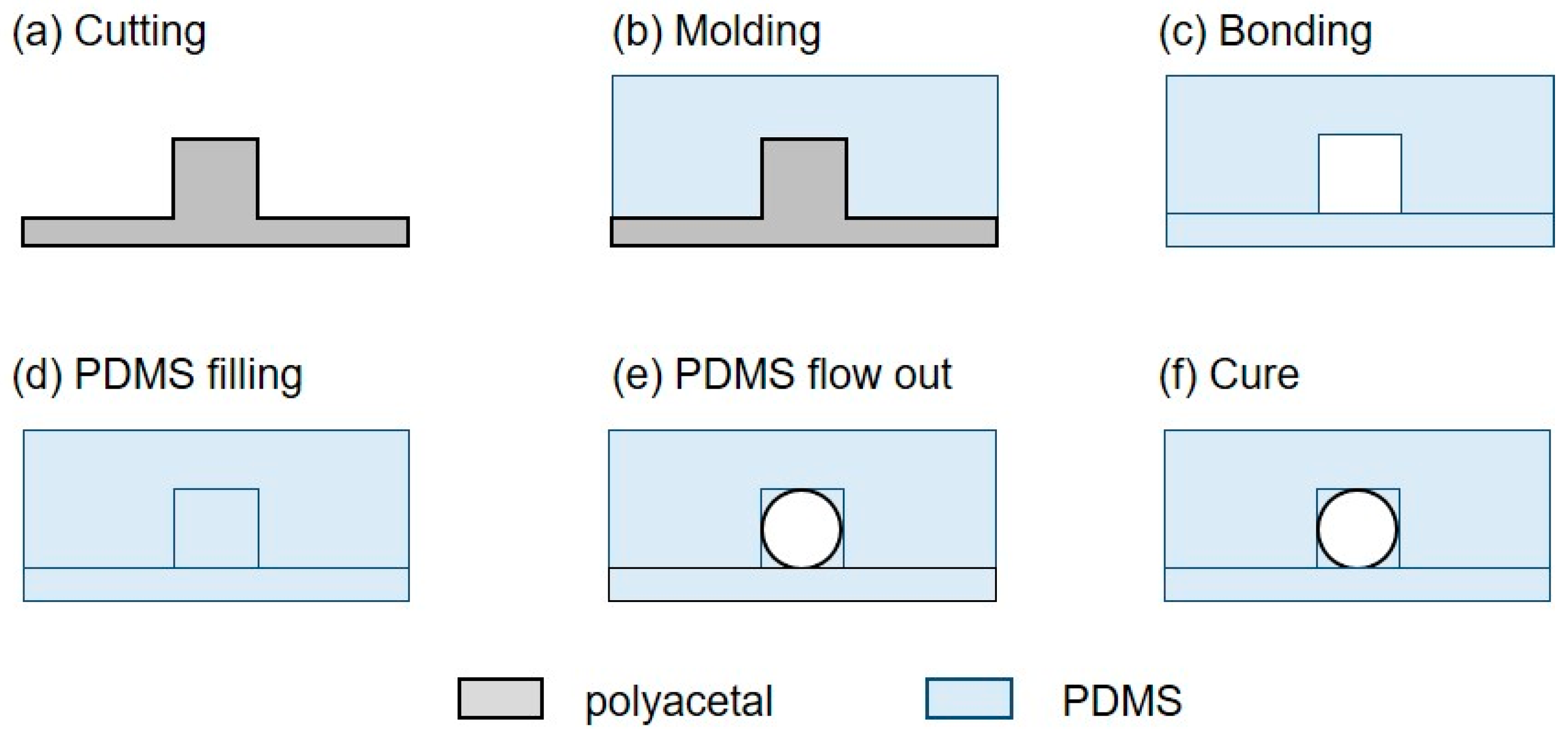
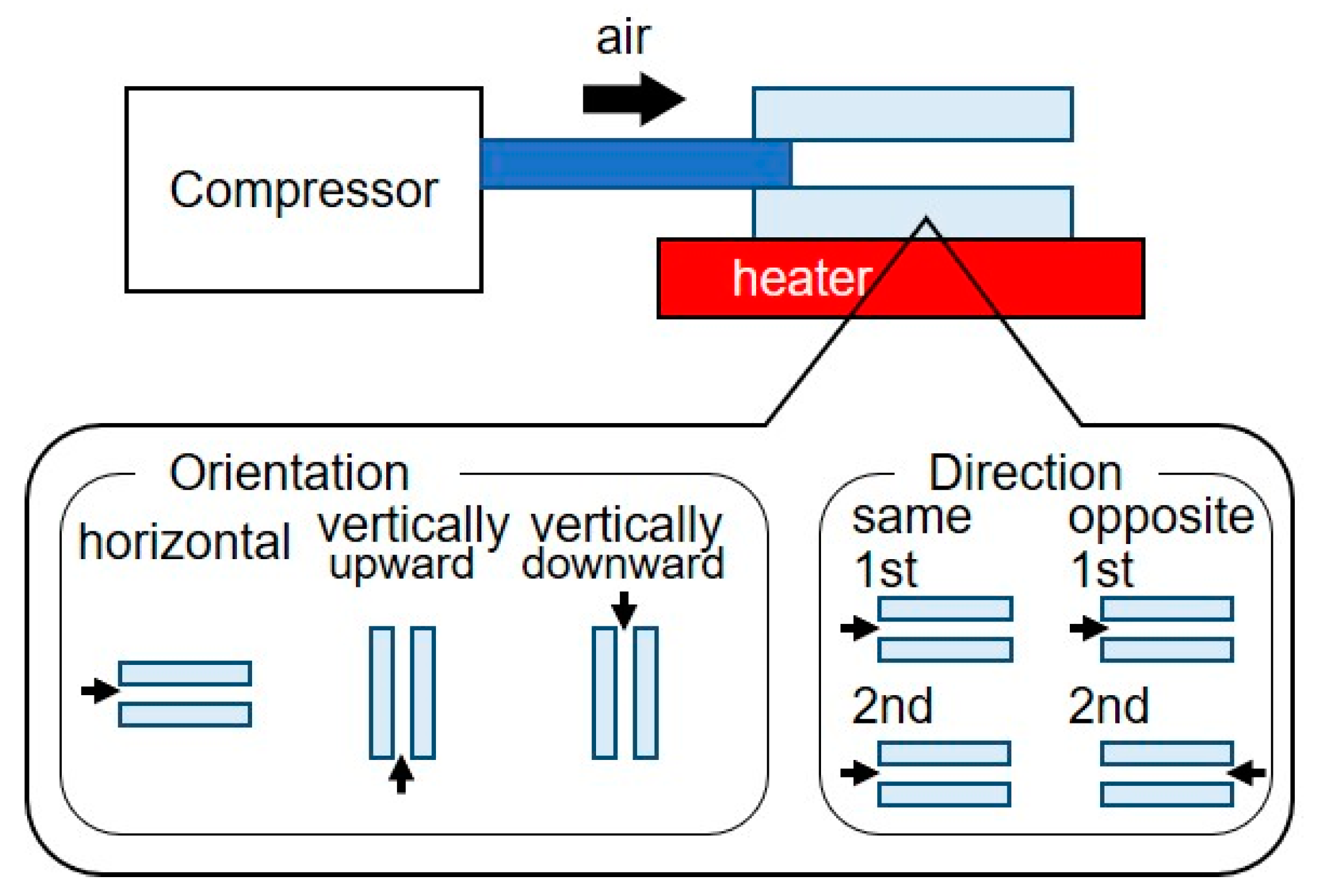
Figure 2 displays the experimental setup. The rectangular cross-sectional microchannel was connected, using a stainless pipe of 1 mm in diameter (inlet), to a pressure source (OFP-07005, Iwata, Kanagawa, Japan) via a precise regulator (HPR-100-05, Tokyo Meter, Kanagawa, Japan). Using the precise regulator, the pressure of the compressed air was set to 10 kPa. The pressure was adjusted by trial and error method; at low pressure range (0 to 5 kPa), the extrusion speed of uncured PDMS was low, resulting in no penetration; at high pressure range (50 to 100 kPa), the extrusion speed was high, resulting in excessive pushing out of uncured PDMS. After pushing out the filled PDMS in the microchannel, the microchannel was heated on a hot plate, maintaining the compressed airflow. The curing temperature should be 120 °C, because the circularity decreased a few % at 100 °C. The microchannel was sliced using a microtome (THK, Kenis, Osaka, Japan) to analyze the circularity of the circular cross-section along the longitudinal direction. Dynamic changes in the residual PDMS in the microchannel and its slices were observed using a digital microscope (MS-200, Asahikogaku, Tokyo, Japan).
3.2. Parameters for Circular Cross-Section
The shape of the cross-section was determined by the shape of the residual PDMS covering the rectangular cross-sectional microchannel, which was determined by the balance of surface tension, gravity, and local pressure applied to the PDMS in the microchannel. Surface tension is a material constant. The direction of gravity was vertically downward, and therefore, the effect of gravity could be controlled by the orientation of the microchannel. The local pressure was different at the inlet and outlet; the pressure at the inlet was applied pressure; that at the outlet was atmospheric pressure. In repeated processes, the position from the inlet could be changed by the flow direction, that is, switching or non-switching the position of the inlet between the first inlet and outlet. Therefore, we chose orientation and flow direction as the parameters to control the circulatory performance.
Figure 2 displays the experimental conditions influencing the circularity of the circular cross-sectional microchannel. For the orientation, we set the microchannel horizontally, vertically upward, or vertically downward. When the microchannel was aligned vertically upward or downward, it was sandwiched and fixed between steel blocks placed on a hot plate to cure the residual PDMS. For the flow direction, the microchannel was set in the same or opposite direction. That is, the same direction did not require switching the inlet between the first inlet and outlet, whereas the opposite direction required switching.
3.3. Analysis of Microchannel Circularity
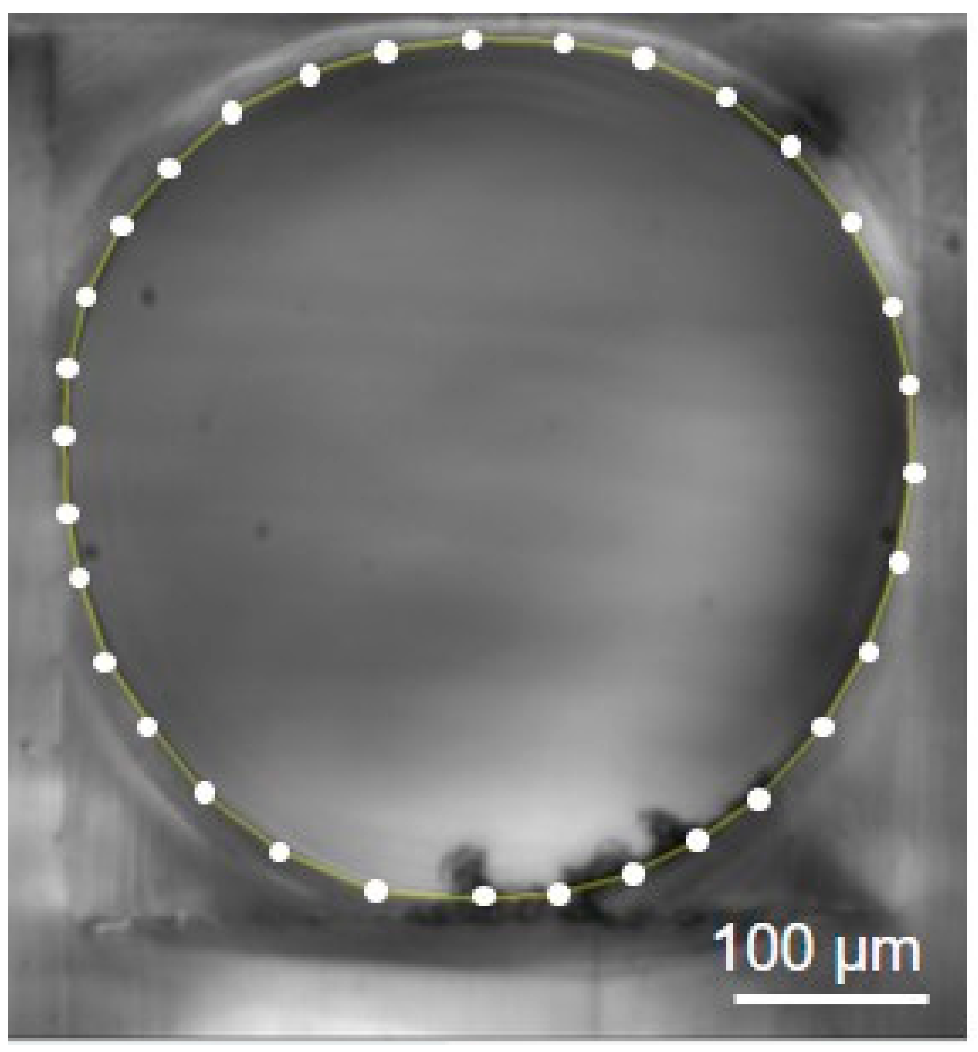
We selected the circularity parameter to measure the circular degree of the microchannel cross section. The circularity was calculated using the following equation: circularity = 4π × cross-section area/perimeter2. To measure the circularity, the microchannel was sliced at positions from the inlet. The stainless pipe connected to the microchannel caused deformation in the shape of the microchannel cross-section. Therefore, we omitted the first 3 mm and sliced the 17 mm microchannel along the longitudinal direction every unit millimeter. The cross-sections included 32 approximate polygons, as indicated in Figure 3; the area and perimeter were measured. The circularity was calculated using these parameters. Image analysis was performed using ImageJ (National Institutes of Health, Bethesda, MD, USA).
4. Results
4.1. Formation of Irregularity-Free Circular Cross-Sectional Microchannel
Figure 4 displays the formation process for the circular cross-sectional microchannel without irregularities. Compressed air was introduced into a PDMS-filled rectangular cross-sectional microchannel and reached the outlet. The PDMS inside the microchannel was pushed out 7 s later by the introduction of air (Figure 4a, Video S1). The initial diameter of the microchannel was 340 μm. The air introduction was sustained and the surface of the residual PDMS on the walls of the microchannel deformed 10 s later (Figure 4b). The majority of the residual PDMS was pushed against the walls and moved aside, resulting in the formation of depressions. Simultaneously, protrusions of 106 μm in height and 489 μm in width appeared at both ends of the depressions (red arrows in Figure 4b). This made narrow necks along the microchannel. The rate of the protrusion formation was initially 1.0 count/s. The protrusions moved downstream along the microchannel at an average of 2.54 mm/s until they reached the outlet (Figure 4b–d). While the formations and movements of the protrusions were repeated, the formation rate, dimensions, and speed of the protrusions gradually decreased. After approximately 1 min, the rate of the protrusion formation was 0.20 count/s and the speed was 0.84 mm/s. The height and width were 97 and 554 μm, respectively. The formation of the protrusions virtually stopped (~0.01 count/s) 3 to 4 min later; the speed was 0.20 mm/s. The height and width were 81 and 606 μm, respectively. This movement of the protrusions caused a fluctuation of the local pressure in the microchannel. Following this protrusion behavior, the dynamic formations and movements of the protrusions in the microchannel stabilized and the microchannel had a smooth surface without irregularities.
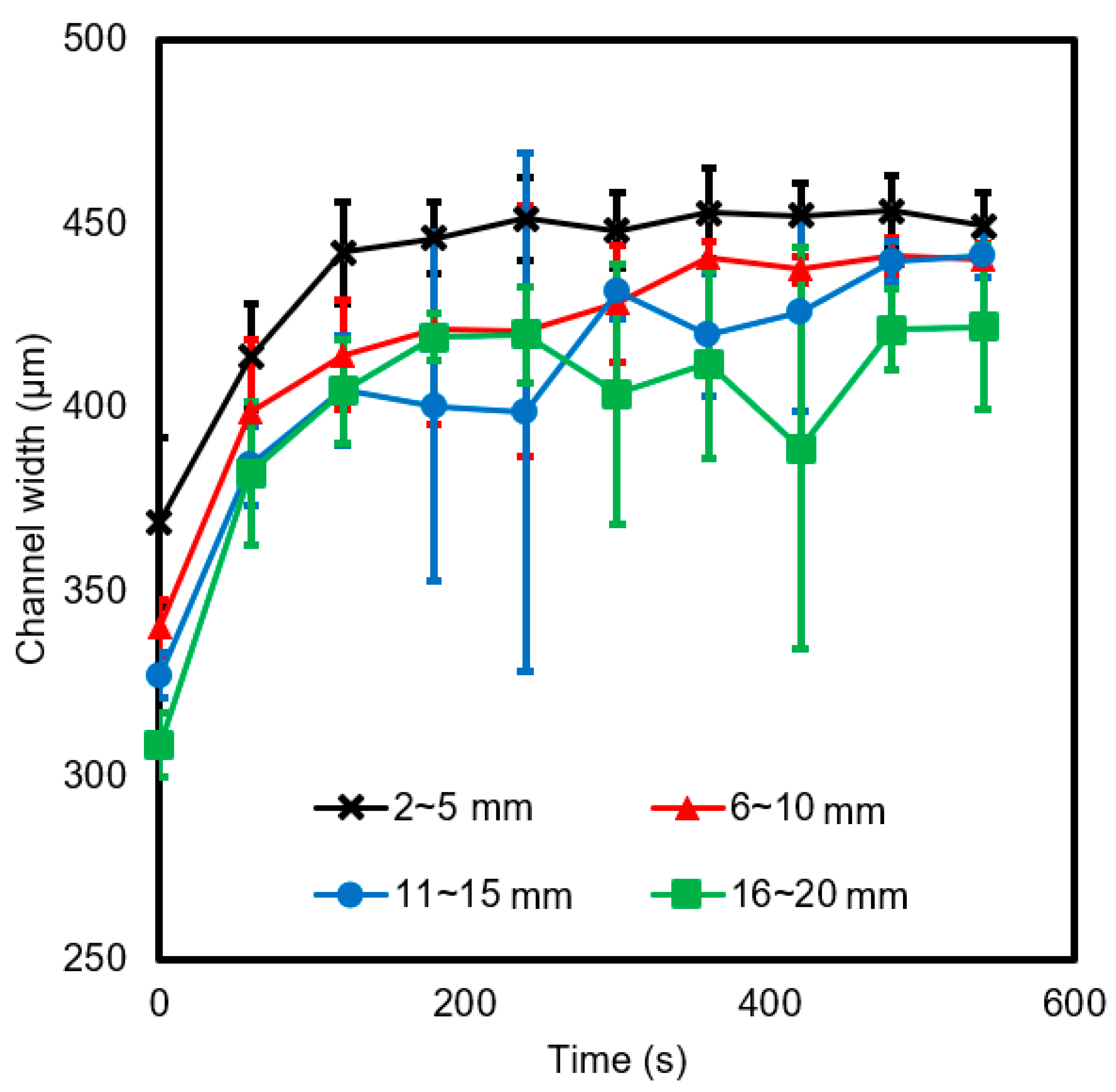
Then, we measured the temporal changes in the diameter of the microchannel (Figure 5). The microchannel was divided into four zones; 2–5 mm, 6–10 mm, 11–15 mm, and 16–20 mm from the microchannel inlet. The diameters in the different zones demonstrated similar trends; the rate of diameter change was initially high and gradually slowed. In the 2–5 mm zone, the diameter became stable at 442 μm, 120 s later. In the 6–10 and 11–15 mm zones, the plots were virtually similar; the diameters reached 441 μm. In the 16–20 mm zone, the diameter at 540 s was the smallest at 422 μm. Certain data points had large error bars caused by the passage of protrusions. Using trial and error methods, the durations of the air introduction to achieve smooth surfaces were determined to be 20 min in the first process and 60 min in the second process. The shrinkage of PDMS during the curing process can be negligible. The shrinkage of the PDMS coating can be calculated to be less than 1 μm, which is small enough in comparison to the diameter of the microchannel, considering that the thickness of the PDMS coating was less than 40 μm and the shrinkage rate was less than 2% [23].
4.2. Circularity of Circular Cross-Section along Microchannel
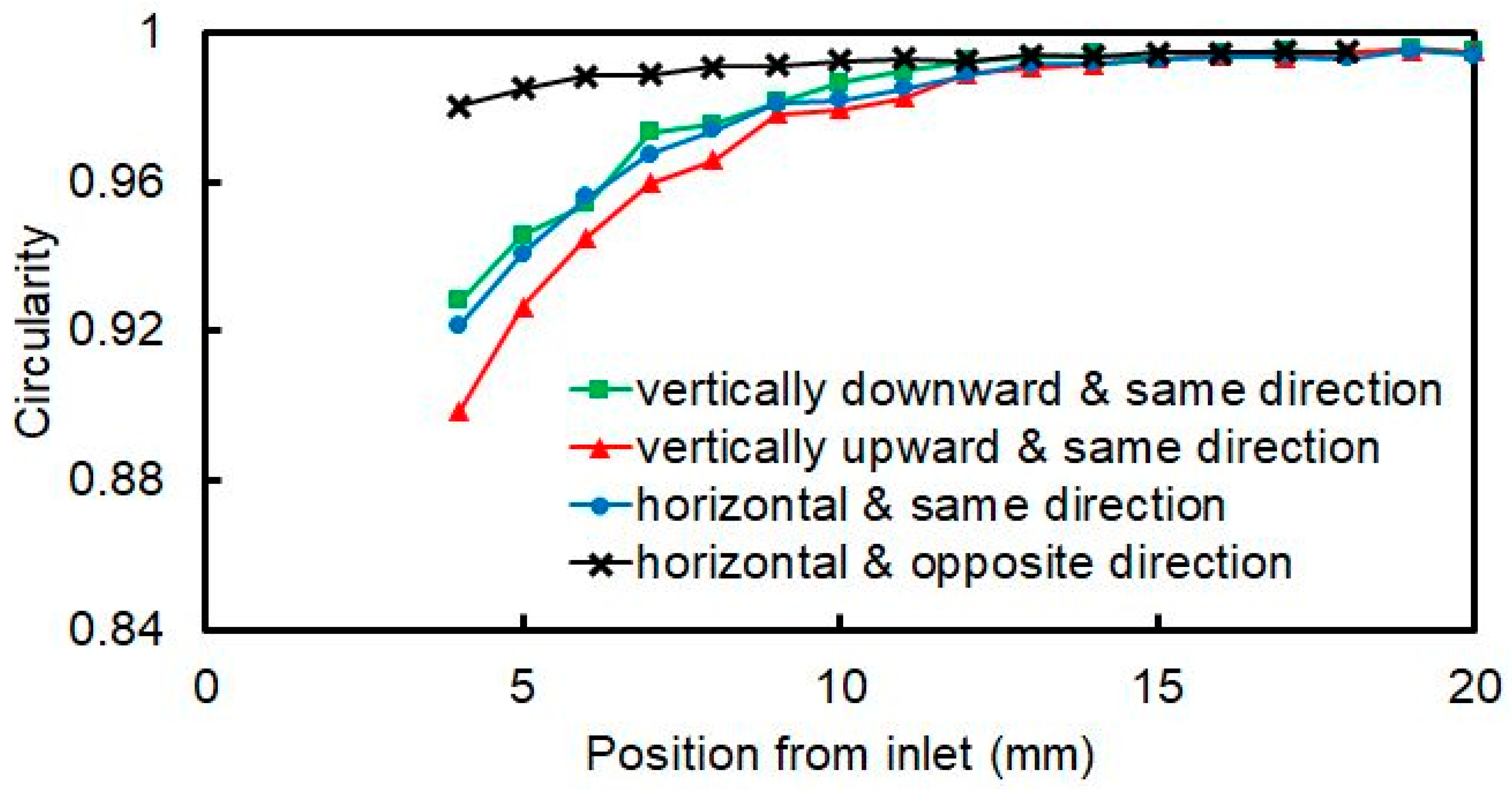
Figure 6 displays the circularity of the microchannel cross-sections along the longitudinal direction. The position is the distance from the inlet in the first process. To compare the circularity in the horizontal, vertically upward, and vertically downward orientations, we performed the process in the same direction. In all orientations, the circularity was greater than 0.99 in the range from 12 to 20 mm from the inlet. In the range from 3 to 12 mm, the circularity decreased owing to the high pressure near the inlet. The circularity at 3 mm from the inlets was 0.92, 0.93, and 0.90 for the horizontal, vertically upward, and vertically downward cases, respectively.
The circularity in the same and opposite directions was compared in the horizontal orientation. In the case of the horizontal opposite direction, the circularity was greater than 0.99 at each position in the range from 3 mm to 17 mm. Even at 3 mm from the inlet, where the circularity was the worst, it was 0.99. We tried to apply this method to the microfabricated rectangular cross-sectional microchannel, whose original square cross-section was 50 μm high, 50 μm wide, and 2 cm long, but the uncured PDMS was not pushed out due to its small cross-sectional area and high viscosity. From these results, we determined that the local pressure distribution and fluctuation influenced the circularity, whereas gravity did not.
4.3. Cross-Sectional Images
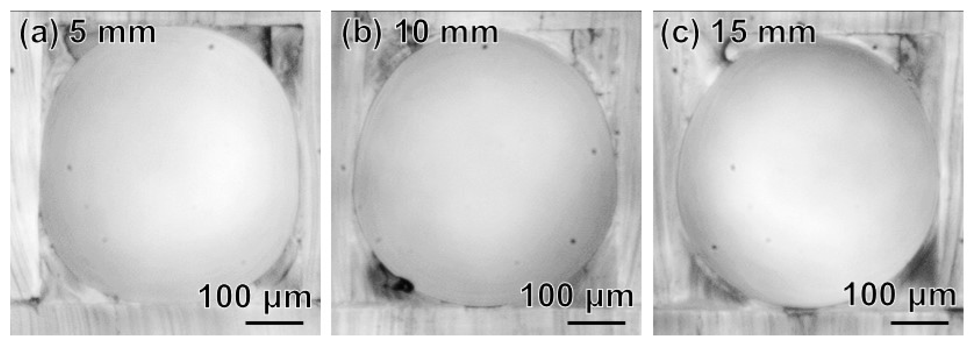
Figure 7 displays cross-sectional images of the microchannel fabricated in the horizontal orientation and same direction. Figure 7a–c are cross-sectional images at 5, 10, and 15 mm from the inlet, respectively. The walls of the rectangular cross-sectional microchannel were exposed near the inlet (Figure 7a), whereas they were covered by PDMS near the outlet (Figure 7c). The excessive pushing-out of the PDMS caused low circularity. The pressure near the inlet (virtually the applied pressure) was greater than that near the outlet (virtually atmospheric pressure). This pressure distribution along the microchannel was caused by pressure loss along the microchannel. High pressure pushed out more PDMS, resulting in an exposed rectangular cross-section.
Figure 8 displays cross-sectional images of the microchannel fabricated in the horizontal orientation and opposite direction. Figure 8a–c are cross-sectional images at 5, 10, and 15 mm from the first inlet, respectively. Compared to the microchannel fabricated in the horizontal orientation and same direction, the thickness of the PDMS coating from the inlet to outlet was virtually constant. The pressure distribution switched between the two processes. Thus, the PDMS near the inlet was excessively pushed out in the first process, and the PDMS near the outlet in the first process was excessively pushed out in the second process. This averaged the thickness of the PDMS coating on the microchannel wall.
5. Conclusions
We developed a method for forming a highly circular cross-sectional microchannel without irregularities. The method was initiated by filling a rectangular cross-sectional microchannel with PDMS, introducing air to push the PDMS out and curing the residual PDMS on the wall of the microchannel. With the introduction of air, the surface deformation caused by the pressure distribution and fluctuation gradually disappeared, and the surface became smooth. To obtain high circularity in the cross-sections of the microchannel along the longitudinal direction, gravity and local pressure were examined. The process in the horizontal orientation and opposite direction of the airflow formed a highly circular cross-section, greater than 0.99. In the future, we will fabricate circular cross-sectional microchannels with small diameters, curves, bifurcations, and confluences to reproduce in vivo flows in biological microchannels.
Supplementary Materials
The following supporting information can be downloaded at: https://0-www-mdpi-com.brum.beds.ac.uk/article/10.3390/micro2020021/s1, Video S1: Motion of uncured PDMS protrusions along a channel.
Author Contributions
Conceptualization, T.I.; methodology, S.I. and T.I.; validation, S.I.; formal analysis, S.I. and T.I.; investigation, S.I.; writing, S.I. and T.I.; supervision, T.I.; project administration, T.I. All authors have read and agreed to the published version of the manuscript.
Funding
This research received no external funding.
Institutional Review Board Statement
Not applicable.
Informed Consent Statement
Not applicable.
Conflicts of Interest
The authors declare no conflict of interest.
References
- Liu, Y.; Jiang, X. Why microfluidics? Merits and trends in chemical synthesis. Lab Chip 2017, 17, 3960–3978. [Google Scholar] [CrossRef] [PubMed]
- Convery, N.; Gadegaard, N. 30 years of microfluidics. Micro Nano Eng. 2019, 2, 76–91. [Google Scholar] [CrossRef]
- Duncombe, T.A.; Tentori, A.M.; Herr, A.E. Microfluidics: Reframing biological enquiry. Nat. Rev. Mol. Cell Biol. 2015, 16, 554–567. [Google Scholar] [CrossRef] [PubMed] [Green Version]
- Weibel, D.B.; Whitesides, G.M. Applications of microfluidics in chemical biology. Curr. Opin. Chem. Biol. 2006, 10, 584–591. [Google Scholar] [CrossRef] [PubMed]
- Lei, K.F. Microfluidic systems for diagnostic applications: A review. J. Lab. Autom. 2012, 17, 330–347. [Google Scholar] [CrossRef] [PubMed] [Green Version]
- Preetam, S.; Nahak, B.K.; Patra, S.; Toncu, D.C.; Park, S.; Syväjärvi, M.; Orive, G.; Tiwari, A. Emergence of microfluidics for next generation biomedical devices. Biosens. Bioelectron. 2022, 10, 200206. [Google Scholar] [CrossRef]
- Lima, R.; Wada, S.; Tanaka, S.; Takeda, M.; Ishikawa, T.; Tsubota, K.; Imai, Y.; Yamaguchi, T. In vitro blood flow in a rectangular PDMS microchannel: Experimental observations using a confocal micro-PIV system. Biomed. Microdevices 2008, 10, 153–167. [Google Scholar] [CrossRef] [Green Version]
- Takeishi, N.; Ito, H.; Kaneko, M.; Wada, S. Deformation of a red blood cell in a narrow rectangular microchannel. Micromachines 2019, 10, 199. [Google Scholar] [CrossRef] [Green Version]
- Zhou, S.; Giannetto, M.; Decourcey, J.; Kang, H.; Kang, N.; Li, Y.; Zheng, S.; Zhao, H.; Simmons, W.R.; Wei, H.S.; et al. Oxygen tension-mediated erythrocyte membrane interactions regulate cerebral capillary hyperemia. Sci. Adv. 2019, 5, eaaw4466. [Google Scholar] [CrossRef] [Green Version]
- Ishida, T.; Shimamoto, T.; Ozaki, N.; Takaki, S.; Kuchimaru, T.; Kizaka-Kondoh, S.; Omata, T. Investigation of the influence of glucose concentration on cancer cells by using a microfluidic gradient generator without the induction of large shear stress. Micromachines 2016, 7, 155. [Google Scholar] [CrossRef] [Green Version]
- Grist, S.M.; Nasseri, S.S.; Laplatine, L.; Schmok, J.C.; Yao, D.; Hua, J.; Chrostowski, L.; Cheung, K.C. Long-term monitoring in a microfluidic system to study tumour spheroid response to chronic and cycling hypoxia. Sci. Rep. 2019, 9, 17782. [Google Scholar] [CrossRef] [PubMed] [Green Version]
- Becker, H.; Locascio, L.E. Polymer microfluidic devices. Talanta 2002, 56, 267–287. [Google Scholar] [CrossRef]
- Tithof, J.; Kelley, D.H.; Mestre, H.; Nedergaard, M.; Thomas, J.H. Hydraulic resistance of periarterial spaces in the brain. Fluids Barriers CNS 2019, 16, 19. [Google Scholar] [CrossRef] [PubMed] [Green Version]
- Mortensen, N.A.; Okkels, F.; Bruus, H. Reexamination of Hagen-Poiseuille flow: Shape dependence of the hydraulic resistance in microchannels. Phys. Rev. E 2005, 71, 057301. [Google Scholar] [CrossRef] [Green Version]
- Pivlin, I.V.; Peng, Z.; Karniadakis, G.E.; Buffet, P.A.; Dao, M.; Suresh, S. Biomechanics of red blood cells in human spleen and consequences for physiology and disease. Proc. Natl. Acad. Sci. USA 2016, 113, 7804–7809. [Google Scholar]
- Ciftlik, A.T.; Ettori, M.; Gijs, M.A.M. High Throughput-Per-Footprint Inertial Focusing. Small 2013, 9, 2764–2773. [Google Scholar] [CrossRef]
- Mori, D.; Yano, K.; Tsubota, K.; Ishikawa, T.; Wada, S.; Yamaguchi, T. Simulation of platelet adhesion and aggregation regulated by fibrinogen and von Willebrand factor. Thromb. Haemost. 2008, 99, 108–115. [Google Scholar]
- He, F.; Xu, H.; Cheng, Y.; Ni, J.; Xiong, H.; Xu, Z.; Sugioka, K.; Midorikawa, K. Fabrication of microfluidic channels with a circular cross section using spatiotemporally focused femtosecond laser pulses. Opt. Lett. 2010, 35, 1106–1108. [Google Scholar] [CrossRef]
- Gallab, M.; Tomita, K.; Omata, S.; Arai, F. Fabrication of 3D capillary vessel models with circulatory connection ports. Micromachines 2018, 9, 101. [Google Scholar] [CrossRef] [Green Version]
- Wang, G.-J.; Ho, K.-H.; Hsu, S.-H.; Wang, K.-P. Microvessel scaffold with circular microchannels by photoresist melting. Biomed. Microdevices 2007, 9, 657–663. [Google Scholar] [CrossRef]
- Nakano, T.; Itoyama, T.; Yoshida, K.; Sawada, Y.; Ikeda, S.; Fukuda, T.; Matsuda, T.; Neguro, M.; Arai, F. Multiscale fabrication of a transparent circulation type blood vessel simulator. Biomicrofluidics 2010, 4, 046505. [Google Scholar] [CrossRef] [PubMed] [Green Version]
- Abdelgawad, M.; Wu, C.; Chien, W.-Y.; Geddie, W.R.; Jewett, M.A.S.; Sun, Y. A fast and simple method to fabricate circular microchannels in polydimethylsiloxane (PDMS). Lab Chip 2011, 11, 545–551. [Google Scholar] [CrossRef] [PubMed]
- Lee, S.W.; Lee, S.S. Shrinkage ratio of PDMS and its alignment method for the wafer level process. Microsyst. Technol. 2008, 14, 205–208. [Google Scholar] [CrossRef]
Figure 1.
Fabrication process of circular cross-sectional microchannel. (a) cutting a polyacetal block for a mold. (b) Molding of a PDMS replica. (c) Bonding of a PDMS replica and a PDMS plate. (d) Uncured PDMS filling into a PDMS channel. (e) Pushing uncured PDMS out from the channel by air introduction. (f) Cure of residual PDMS in the channel.

Figure 2.
Experimental setup to fabricate circular cross-sectional microchannel, and conditions influencing the circularity. Orientation of microchannel and direction of airflow are examined.
Figure 2.
Experimental setup to fabricate circular cross-sectional microchannel, and conditions influencing the circularity. Orientation of microchannel and direction of airflow are examined.

Figure 3.
Polygonal approximation of circular cross-sectional microchannel.

Figure 4.
Behavior of non-cured PDMS on walls of rectangular cross-sectional microchannel. (a) 7 s from the air introduction. (b) 10 s. (c) 11 s. (d) 12 s.
Figure 4.
Behavior of non-cured PDMS on walls of rectangular cross-sectional microchannel. (a) 7 s from the air introduction. (b) 10 s. (c) 11 s. (d) 12 s.

Figure 5.
Temporal change of diameter of microchannel in different area. Averaged diameters and standard deviations as error bars are plotted (N = 3).
Figure 5.
Temporal change of diameter of microchannel in different area. Averaged diameters and standard deviations as error bars are plotted (N = 3).

Figure 6.
Circularity as function of distance from outlet.

Figure 7.
Cross-sectional images of microchannel fabricated in horizontal orientation and same direction. (a) 5 mm from the inlet. (b) 10 mm. (c) 15 mm.
Figure 7.
Cross-sectional images of microchannel fabricated in horizontal orientation and same direction. (a) 5 mm from the inlet. (b) 10 mm. (c) 15 mm.

Figure 8.
Cross-sectional images of microchannel fabricated in horizontal orientation and opposite direction. (a) 5 mm from the inlet. (b) 10 mm. (c) 15 mm.
Figure 8.
Cross-sectional images of microchannel fabricated in horizontal orientation and opposite direction. (a) 5 mm from the inlet. (b) 10 mm. (c) 15 mm.

Publisher’s Note: MDPI stays neutral with regard to jurisdictional claims in published maps and institutional affiliations. |
© 2022 by the authors. Licensee MDPI, Basel, Switzerland. This article is an open access article distributed under the terms and conditions of the Creative Commons Attribution (CC BY) license (https://creativecommons.org/licenses/by/4.0/).
Share and Cite
MDPI and ACS Style
Inagaki, S.; Ishida, T. Fabrication of Irregularity-Free, Highly Circular Cross-Sectional Microchannel. Micro 2022, 2, 325-333. https://0-doi-org.brum.beds.ac.uk/10.3390/micro2020021
AMA Style
Inagaki S, Ishida T. Fabrication of Irregularity-Free, Highly Circular Cross-Sectional Microchannel. Micro. 2022; 2(2):325-333. https://0-doi-org.brum.beds.ac.uk/10.3390/micro2020021
Chicago/Turabian StyleInagaki, Satoru, and Tadashi Ishida. 2022. "Fabrication of Irregularity-Free, Highly Circular Cross-Sectional Microchannel" Micro 2, no. 2: 325-333. https://0-doi-org.brum.beds.ac.uk/10.3390/micro2020021