
Exsolution Catalysts—Increasing Metal Efficiency
by
 , , , and
Lorenz Lindenthal
 ,
,
Richard Buchinger
,
Hedda Drexler
,
Florian Schrenk
,
Thomas Ruh
and
Christoph Rameshan
* TU Wien, Institute of Materials Chemistry, Getreidemarkt 9/165, 1060 Vienna, Austria
*
Author to whom correspondence should be addressed.
Encyclopedia 2021, 1(1), 249-260; https://0-doi-org.brum.beds.ac.uk/10.3390/encyclopedia1010023
Submission received: 31 January 2021
/
Revised: 14 February 2021
/
Accepted: 19 February 2021
/
Published: 25 February 2021
(This article belongs to the Section Material Sciences)
Definition
:Exsolution catalysts are perovskite oxide-based materials that can exsolve catalytically active dopant elements as nanoparticles covering the surface, while the perovskite backbone can act as a stable support material. Thus, under proper conditions, a highly catalytically active and stable catalyst surface can be achieved. For many catalytic materials, precious metals or non-abundant elements play a key role in high catalytic activity. As these elements are often expensive or their supply is ecologically and ethically problematic, the replacement, or at the least reduction in the necessary amount used, is a common aim of current research. One strategy to do so is utilizing exsolution catalysts, as the active elements can be very selectively exsolved, and hence only very small doping amounts are sufficient for excellent results. This approach enables catalyst design with very high active metal efficiency.
1. Introduction
Heterogeneous catalysis is the backbone of our modern society. Many large scale industrial processes depend on catalysts, e.g., the production of fertilizers, fuels, solvents or base chemicals [1]. Additionally, with the current demand for a sustainable future without dependence on fossil fuels, heterogeneous catalysis is becoming crucially important [2]. The major focus is on either utilizing CO2 (as an abundant carbon source) or to find ways to store excess renewable energy in a practical way (e.g., by chemical energy conversion) [3].
Although many catalytic processes have been established for years, a constant development of catalyst materials remains necessary to increase efficiency and economic profitability. This is the driving force for numerous studies for novel catalyst materials or the improvement of existing systems. A common goal of all the current research efforts is the desire to reduce the amount of used precious metals or non-abundant elements [4], and, in spite of that, keeping or even improving catalytic performance. The need for this arises because several raw metals sources are very rare or their supply is ecologically and ethically problematic. Furthermore, in situ (operando) spectroscopic or microscopic techniques for catalyst characterisation in reaction environments are now highly advanced, thus enabling novel fundamental insights into reaction pathways and correlations between catalyst composition, structure and reactivity [5]. Combining all this has opened various routes to strongly reduce the amount of required precious metals or to gradually replace them completely by cheaper materials, utilizing abundant oxides or metals. As a result, a new level of catalyst design has been reached.
The most widely used material class in heterogeneous catalysis are metal oxides. They play an important role either as a support material due to their specific properties (high surface area, porosity, reducibility, thermal stability, etc. [6]) or as a catalytically active phase (especially for redox mechanisms [7]). For example, mixed oxides of Mo, V, Te and Nb are highly efficient catalysts for the selective oxidation of lower alkanes [8]. Hydrogen production by a high temperature water–gas shift (WGS) is traditionally conducted on CrO3–Fe2O3 catalysts [9]. Moreover, supported metal catalysts utilize the oxide as the structural backbone, for high dispersion and for the stable anchoring of metal particles (ensuring a high surface area and thermal stability of the particles), thus also potentially improving the reactivity by creating an active interface or for, e.g., spill-over mechanisms. Widmann and Behm demonstrated that for CO oxidation on Au/TiO2 catalysts, the necessary active oxygen species is only formed at the boundary of the Au–oxide interface, enabling high reactivity [10].
There are many other options for catalyst design and to reduce the amount of active metal species, ranging from carbon supported nanoparticles, through metal organic frameworks and hybrid materials to single atom catalysis and others, which are discussed in detail in, e.g., the great book from Chorkendorff and Niemantsverdriet [11]. In this article, we want to highlight the possibility to reduce the amount of active metal species by utilizing the very versatile materials class of (doped) perovskite oxides [12].
Perovskite oxides have the general formula ABO3 with A and B being large and small cations, respectively. In terms of catalysis, the most interesting feature of this materials class is that the B-site can be doped with catalytically active elements. Consequently, the perovskite host lattice acts as a reservoir that can release these dopants: either upon reductive treatment or in reducing reaction environments. During exsolution, dopants migrate to the surface where they form stable nanoparticles, thus creating highly active catalyst surfaces [13].
With our own research, we want to demonstrate how this exsolution approach can serve as an elegant pathway to reduce the amount of catalytically active elements necessary for an excellent catalyst. We show this in this work through the example of the reverse water–gas shift reaction (rWGS), conducted on a perovskite host lattice with Co-doping on the B-site and a stepwise reduction in the amount of active cobalt by varying the catalyst composition. Even using a low Co-doping yielded very promising results.
2. Principles of Exsolution
2.1. Perovskite Oxides
The materials class of perovskite offers a very large scope for material design. For both A-site and B-site cations, a great variety of choices is conceivable. Additionally, for either lattice site, a combination of two or more (in principal with no restrictions) cations instead of a single element can be utilized to further tune the properties of a material. The possibilities range from doping a main component with only small amounts of another element to combining equal parts of several elements. Furthermore, sub-stoichiometric perovskites exist, where either A- or B-sites are not fully occupied. All this makes the materials class highly versatile, as all incorporated elements contribute to the properties of the perovskite. Thus, a vast range of overall properties can be achieved. Hence, perovskites can be utilized for many different applications.
Two main requirements must be considered to predict if a stable structure can be achieved with a given combination of cations:
(i) The first criterion is the ratio between the size of A- and B-site cations, described by the Goldschmidt tolerance factor [14]. The closer its value is to one, the more perfectly the cations fit into the ideal cubic perovskite structure. Still, this is no strict condition, as stable materials are possible across a range of these factors. Stabilization in the case of size ratios deviating not too far from the ideal case occurs via distortion of the structure, resulting in, e.g., orthorhombic, rhombohedral or tetragonal symmetry [15].
(ii) The second requirement is that charge balance needs to be reached, taking into account the possible oxidation states of the used cations. Ideally, the positive cation charge should add up to six; however, minor deviations can be tolerated by including structural defects, such as oxygen vacancies. In fact, the incorporation of defects can even be beneficial (and might be intended), e.g., for better ionic and electronic conductivity or to improve the surface redox chemistry [16]. Additionally, using redox active elements and the possibility of sub-stoichiometry increase the flexibility with respect to charge balance.
In order for a perovskite to exhibit exsolution, it is necessary that it incorporates an easily reducible metal (which is then selectively reduced and exsolved). Examples for metals that have been used are Fe [17,18], Co and Ni [19], or Pd, Rh and Pt [20]. At the same time, if the material is reduced too easily altogether, it will undergo decomposition under reducing conditions without exhibiting observable exsolution. Therefore, doping approaches with an easily reducible dopant within an otherwise very stable structure are frequently chosen. Furthermore, the reduction of a cation is accompanied by oxygen vacancy formation, which is the reason for oxygen anion conductivity being necessary. Thus, defect rich materials are often used for exsolution applications [21].
2.2. Exsolution Mechanism
As mentioned above, oxygen vacancies play a central role in exsolution [19]. Their formation occurs first when exposing a reducible perovskite to reductive conditions. When the oxygen vacancy formation is pronounced, the perovskite structure is destabilized. After removing surrounding oxygen atoms, a reduced metal atom can be viewed as secluded from the remaining perovskite structure at an atomic scale—it is exsolved [21]. Subsequently, in order to reduce overall energy, such exsolved metal atoms nucleate and grow into small particles. Finally, as these particles induce strain on the surrounding perovskite, they migrate to the surface, which leads to surfaces with homogeneously dispersed nanoparticles [22]. Thus, applying additional strain can enhance the exsolution process as well [23].
The resulting particles can be either monometallic or alloy particles, depending on perovskite composition and used dopants, as well as exsolution parameters. In fact, tuning the particle nature is an ongoing research topic [24]. Moreover, core–shell nanoparticles can be achieved, usually comprising a metal core and an oxide shell [25]. The oxide shell is stabilized by the strong interaction of the particle with the perovskite oxide support. Additionally, the core and shell can be based on different dopant elements, for instance, a metallic Pd core covered by a NiO shell [26].
In principle, exsolution is possible from both A- and B-sites; however, B-site exsolution is more common. Evidently, exsolving from only one site affects stoichiometry. This causes structural destabilization and, thus, is often accompanied by the formation of a layered Ruddledsen–Popper phase [27] or complete segregation of the cations on the other lattice site in order to re-establish stoichiometry. A strategy to overcome this effect is using an already sub-stoichiometric material as a starting point. In this case, the perovskite is even stabilized via establishing stoichiometry after exsolution from the excess site [21].
Reducing conditions are the main driving force for exsolution. These can be achieved simply by exposing the material to a H2 atmosphere at elevated temperatures, but it is also possible to provoke exsolution within less reducing environments, e.g., containing CO or CH4. Consequently, the fine tuning of the exsolution conditions also plays a role in the size and distribution of the exsolved particles (through the corresponding nucleation behavior) [23]. In general, the deciding factors are the temperature and reduction strength of the gas phase, the latter being described by the oxygen chemical potential [28]. Furthermore, in the case of applying a perovskite as the electrode material of an electrochemical cell, it is possible to control the strength of reduction by applying an electrical polarization [29].
Another aspect that kinetically affects the exsolution process is defects within the material, for example, stacking faults or impurity phases [30]. These defects can act as nucleation sites, and thus facilitate exsolution. Moreover, their location defines the final particle distribution, e.g., increased particle density has been observed at grain boundaries and corners [31].
2.3. Applications
A major field of applications for exsolution materials is as an anode material for solid oxide fuel cells (SOFCs). One reason for this is that the additional control via polarization can be readily applied in this case. Furthermore, defect rich perovskites used as anodes are mixed ion–electron conductors, which is immensely beneficial for this kind of application. Examples of utilized systems are Sr0.95(Ti0.3Fe0.63Ni0.07)O3-δ, where exsolution of Ni0.5Fe0.5 nanoparticles could be observed [32], or Sr(Ti0.3Fe0.7Ru0.07)O3-δ, where Ru1-xFex particles were found [33]. In both cases, exsolved particles significantly reduced anode polarization resistance.
The second important field for possible application is heterogeneous catalysis. Perovskites decorated with exsolved nanoparticles exhibit the features of a conventional catalyst design: active nanoparticles on a stable support (the remaining perovskite backbone). Using exsolution as the preparation method, nanoparticle decorated surfaces can be easily achieved, and the creation of the nanoparticles is more time and cost efficient compared to other methods [21]. Furthermore, exsolution is very flexible, and tuning the material composition, and the subsequent particle nature (e.g., alloys, core-shell structures), allows the precise control of the catalyst properties, establishing a multifunctional catalyst architecture (i.e., a combination of metal and oxide surfaces) [34]. Particles prepared by exsolution are anchored into the perovskite support, resulting in increased resistance towards agglomeration and coking [35].
An example of a catalytic system is Rh-doped SrTiO3 for CO2 reduction [36]. In the referenced study, increased activity and CO selectivity were found after the exsolution of Rh-particles. It was suggested by the authors that the combination of active Rh particles and a redox active perovskite surface is responsible for the superior catalyst performance. Another example is the improved water–gas shift activity of Ni- or Co-doped Nd0.6Ca0.4FeO3-δ after exsolution [37]. Combining electrochemistry and catalysis, it was also shown that electrochemical water splitting at a La0.6Sr0.4FeO3-δ anode could be enhanced, after driving the exsolution of Fe via applied polarization [18].
In both fields, among the tremendous advantages of exsolution systems over most conventional materials with supported metal particles is their ability for re-incorporation of the exsolved elements into the perovskite structure [38]. Although this is a kinetically slow process, it can be achieved via oxidation at high temperatures. In the case of the deactivation of the material due to particle agglomeration and sintering, or poisoning (e.g., by coking or sulphur deposition), this re-establishment of the initial state enables an easy regeneration by applying a redox cycle [39]. Upon oxidation of the used catalyst, it is cleaned from depositions, and possibly larger particles are re-integrated into the perovskite host. The active state can be regained by reductively triggering exsolution anew. This way, the lifetime of a catalyst material can be considerably extended.
3. Approach for Improved Catalyst Design
The catalytic reaction utilized in this work—to demonstrate how the catalytically active element content can be reduced—is the rWGS reaction:
which is an equilibrium-limited reaction that is only favored at higher temperatures (the equilibrium point lies around 825 °C). This reaction is of great interest, as it transforms the greenhouse gas CO2 into CO, which is more reactive and can be processed further and be converted into valuable chemicals (i.e., hydrocarbons via the Fischer–Tropsch process or methanol by hydrogenation). Thus, it is a key reaction in many applications related to CO2 utilization and sustainable chemical energy conversion [2].
For the perovskites investigated in more detail in this study, the material Nd0.6Ca0.4FeO3-δ was used as a starting point. This material has a high chemical and thermal stability, which is why it is perfectly suited as a support backbone. The A-site is occupied by Nd and is doped with Ca to introduce a charge imbalance. This leads to advanced defect chemistry, resulting in a higher ionic and electronic conductivity, as well as improved catalytic properties. The B-site metal is Fe, which is known to already have some catalytic activity, e.g., as iron oxide supported by an oxygen carrier material [40].
To optimize the catalytic activity, the B-site of Nd0.6Ca0.4FeO3-δ can be doped with Co. This element is known to be highly active for rWGS [41]. The doped Co can be selectively exsolved, as has been shown already by the authors [34]. Additionally, this exsolution greatly enhances the catalytic performance of the material [12]. However, the production and abundance of Co is limited. Furthermore, a large portion of the mining is carried out under ethically problematic conditions in the Democratic Republic of Congo. Aside from tremendous social impacts, studies show that the mining adversely affects pollution in the region, as well as the health of the local communities [42]. Therefore, it is preferable to use the smallest possible amount of Co, while at the same time still maintaining its beneficial effects.
To test the influence of the amount of Co-doping, four perovskites with varying Co-content were synthesized: the undoped Nd0.6Ca0.4FeO3-δ (Co0), two materials with a low doping amount, Nd0.6Ca0.4Fe0.97Co0.03O3-δ (Co3) and Nd0.6Ca0.4Fe0.9Co0.1O3-δ (Co10) and one sample where the B-site Fe was completely exchanged with Co (Nd0.6Ca0.4CoO3-δ, Co100). In the following, the names given in parentheses are used to refer to the different samples. The syntheses followed a modified Pechini route and are described in detail in previous work [34]. The cation precursors were mixed as nitrate solutions in the desired stoichiometric ratio, and citric acid was added, followed by the evaporation of the solvent and calcination after grinding, leading to perovskite powders.
Subsequently, the various materials were characterized with respect to their catalytic performance and stability under reaction conditions, with the aim to relate their behavior to the Co-content. The stability was investigated utilizing powder X-ray diffraction (XRD) and scanning electron microcopy (SEM) before and after the reaction, revealing changes in the crystallographic phases and the morphology, respectively.
4. Catalyst Characterization
Further information about the experimental procedures can be found in previous works by the authors [12,34,37].
4.1. Catalytic Testing
Catalytic testing of the materials was performed with a flow reactor, using gas flows of 3 mL min−1 for H2 and CO2, respectively, and 6 mL min−1 for Ar as carrier gas. The gas composition at the reactor exit was determined with gas chromatography (GC). In each test run, the first step was an oxidative pre-treatment in O2 at 600 °C for 30 min. After cooling down to 300 °C, the atmosphere was changed to the reaction environment. Then, the temperature was increased to 700 °C in steps of 100 °C, keeping each temperature constant for 60 min [37].
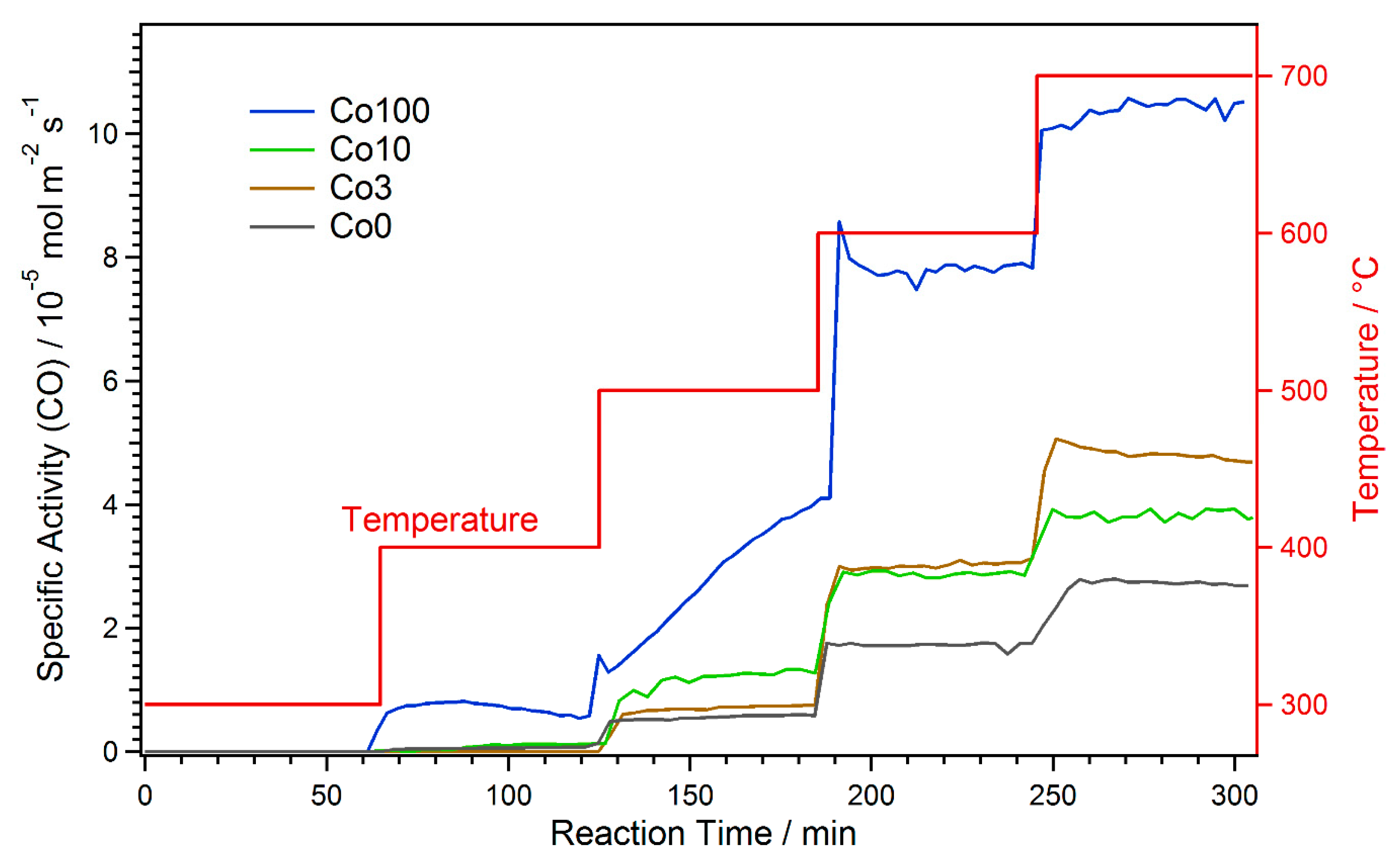
The results of the catalytic measurements are shown in Figure 1 as specific activities with respect to CO formation versus time. The specific activity is the amount of CO formed per time unit and catalyst area (unit: mol m−2 s−1) and was used to allow a direct comparison for the different materials. It was calculated from the amount of CO in the product gas stream, the total gas flow, the amount of catalyst used and the catalyst specific surface area (which was determined via physisorption according to the Brunauer–Emmett–Teller theory, BET) [34].
The catalyst without any Co-doping (black in Figure 1) showed a stepped increase in activity, coinciding with the temperature steps. CO formation started at 400 °C. During the periods of constant temperature, the activity hardly varied, which means no strong early activation or deactivation effects occurred. The catalysts with small amounts of Co-doping (Co3 and Co10, brown and green curves) exhibited a similar behavior. In the case of the Co3 material, it was almost identical to Co0 up to 500 °C. However, at 600 °C, the specific activity was significantly higher with Co-doping. Here, the promoting effect of Co via exsolution of catalytically active nanoparticles comes into effect. At 700 °C, there was a slight initial deactivation. This might be due to the pronounced formation of CaCO3 at this temperature. Further discussion of the formation of new phases is presented in the following sections.
Activation due to exsolution already took place at 500 °C for Co10. This was evident, as the activity showed an initial increase at this temperature due to the ongoing exsolution process. Consequently, the specific activity was higher than for Co0 and Co3 at 500 °C. In contrast, at 600 °C, the activity was the same as for Co3, and at 700 °C it was even lower. The latter observation is due to the fact that for the measurement with Co10, the used catalyst amount was slightly higher. Thus, higher conversions were reached and thermodynamic limitations biased the result (i.e., the back reaction—water–gas shift—becomes more prominent the closer the reaction is to the thermodynamic limit). This bias was only very small at 600 °C, where it was still possible to conclude that Co3 and Co10 have very similar specific activities. This means that the onset temperature of the activation (caused by exsolution, which is easier for the higher Co doping) is the main difference. Additionally, any deactivation effects, as observed for Co3, were obscured at the limit conditions, which is why none can be seen for Co10.
The Co100 catalyst, with only Co on the B-site, showed a very different behavior to the other materials. Already at 400 °C, a significant amount of CO formation could be observed. Likewise, the activity was much higher than for the other catalysts at all temperatures. Furthermore, very strong activation and minor deactivation effects could be observed: at 400 °C, slight activation followed by deactivation was found. The strongest activation took place at 500 °C, where CO formation constantly increased during the whole holding time. This is probably due to the ongoing formation of metallic Co at this temperature. At 600 °C, quick deactivation occurred at the beginning, and at 700 °C, there was slight activation. However, as for Co10, effects due to thermodynamic limitations at 600 °C and, much stronger, at 700 °C were expected.
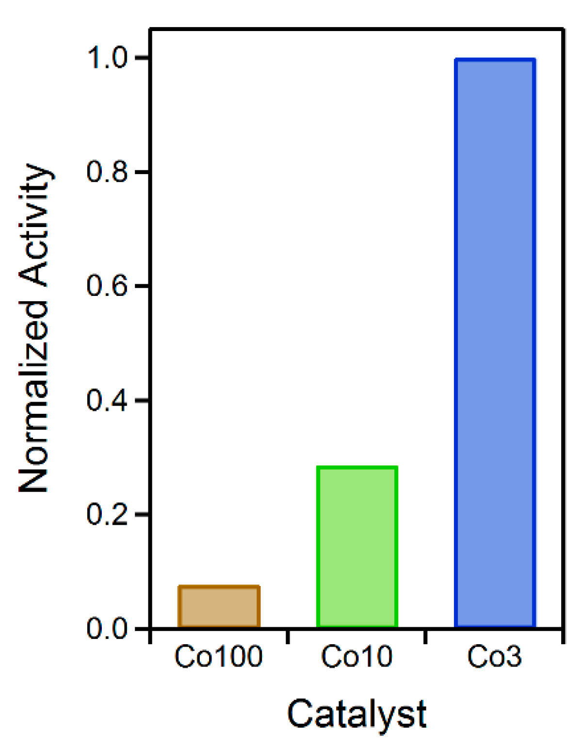
As the aim was to relate the catalytic activity to the Co content of the catalyst, the specific activities at 600 °C (after activation, but before thermodynamic limitations predominate) were normalized to the amount of Co in the respective material (for those that contain Co). These values were additionally normalized to the highest resulting value, because their relative ratios should be emphasized here. Figure 2 depicts the result of this comparison. It is evident that Co3 was the most efficient with respect to the amount of incorporated Co, followed by Co10 (at about a third of efficiency) and Co100 (smaller than a tenth of the efficiency of Co3). These results clearly highlight how the content of catalytically active species can be lowered by rational catalyst design.
4.2. Powder X-ray Diffraction
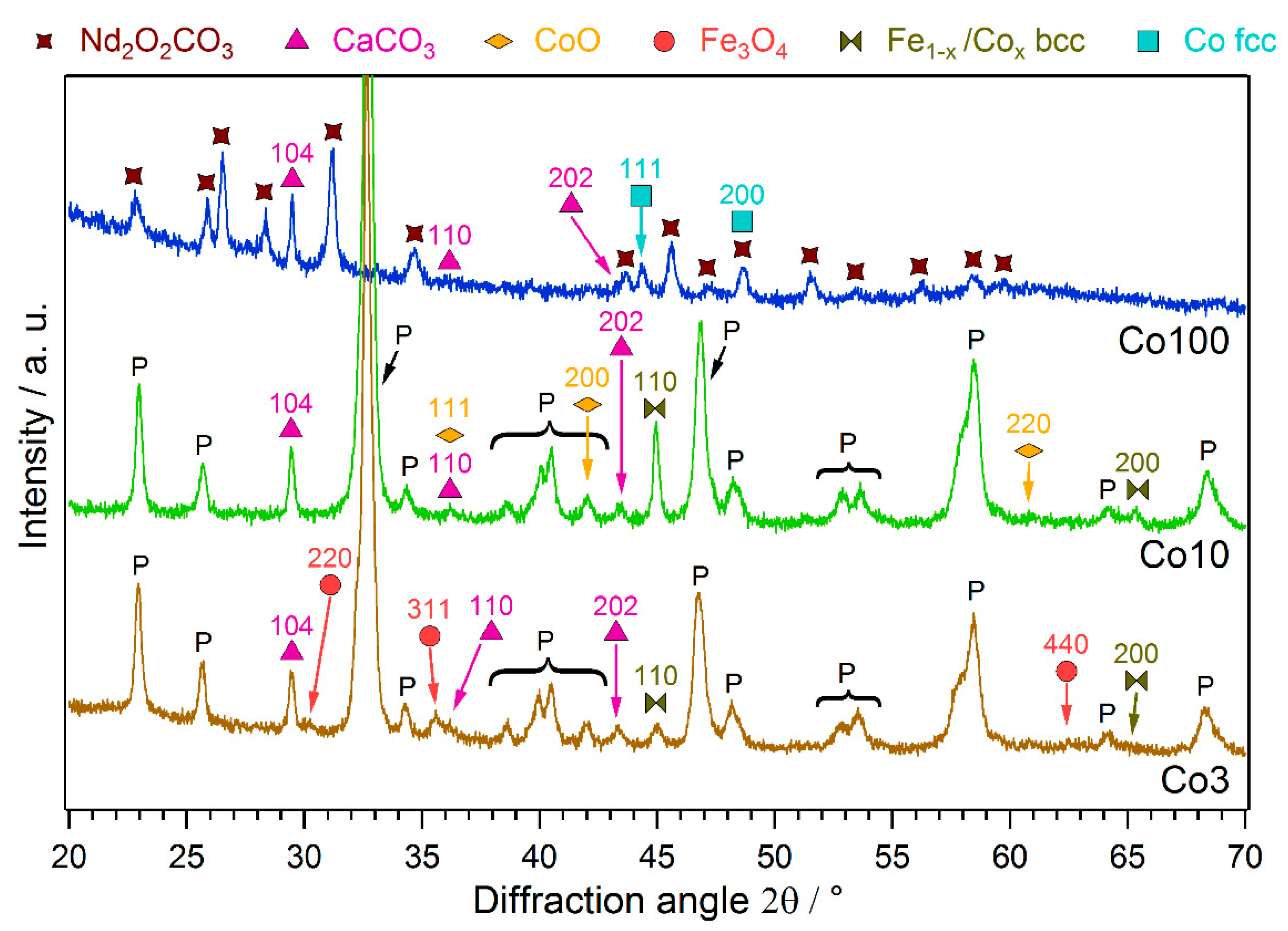
All catalysts were analyzed with powder XRD after the reaction runs. The diffractograms are shown in Figure 3, revealing the formation of additional phases during the reaction. The pristine materials consisted solely of a perovskite phase (not shown here).
For the Co-doped materials Co3 and Co10, the perovskite phase was still the dominant component after the reaction. Some additional phases could be observed, namely, a FeCo alloy and CaCO3, as well as small contributions of Fe3O4 for Co3 and CoO for Co10 (the CoO signals were very weak, but the formation of CoO could additionally be shown with in situ XRD measurements, not presented here). A bcc structure was found for the FeCo phase, indicating a substantial amount of Fe. This alloy can be attributed to an exsolution process; the exsolved amount increased with the higher Co-doping amount in Co10. Furthermore, the formation of this metallic phase enhances the catalytic activity, as discussed in Section 4.1. In contrast, the segregated CaCO3 is an unwanted byproduct, leading to catalyst deactivation (e.g., as observed for Co3 at 700 °C, cf. Figure 1). This segregation of A-site elements as carbonates, especially alkaline earth metals, is a known phenomenon in perovskites [43]. The higher Co content also changed the behavior of the minor oxide formation, resulting in CoO rather than Fe3O4. These oxide phases are a result of rich redox chemistry at the perovskite surfaces. It is not completely clear at this stage whether they are beneficial for the catalytic performance.
The XRD pattern of Co100 looks totally different from the other two. Exchanging Fe entirely with Co destabilized the perovskite structure, resulting in the complete decomposition of this phase during catalytic reaction. Due to the CO2-rich atmosphere, the Nd formed an oxide carbonate phase (Nd2O2CO3) and Ca was present as CaCO3. Co was reduced to a metallic fcc phase, being responsible for the very high catalytic activity of this material. The formation of CaCO3 and a metallic B-site metal phase was analogous to the behavior of the doped materials Co3 and Co10. The activation and deactivation phenomena seen in Figure 1 for Co100 can be attributed to the decomposition and carbonization processes the catalyst undergoes.
4.3. Scanning Electron Microscopy
To see any morphological changes of the Co-doped catalysts during the reaction, they were investigated with SEM. In order to focus on the temperature at which they were compared in Figure 2, additional reaction runs were performed in the reactor, holding the temperature constantly at 600 °C for a few hours. Afterwards, SEM images of these samples were recorded. They can be seen in Figure 4 (second row), where they are shown together with images of the pristine samples (first row).
The emergence of two main features could be observed after the reaction: small, bright particles and larger, smooth crystallites. The small particles were exsolved Co (or FeCo-alloy) particles, proving that the expected exsolution actually occurred. They could be seen most clearly on the surface of Co10. Here, they had sizes around 30 to 40 nm and were very densely and homogeneously distributed. On Co100, these particles were less densely dispersed and also larger, with sizes around 60 to 80 nm. For the Co3 catalyst, only very few such particles were visible. Furthermore, in this case, it was not completely clear if they were really exsolved, because similar features were already present on the pristine surface. Considering the trend of decreasing particle size with reduced Co content, it is also conceivable that most exsolved particles for Co3 were too small to be well-distinguishable given the resolution of the microscope.
The larger crystallites can be attributed to CaCO3. They were most prominent on Co3, but present on all samples (the chosen section of Co10 shows only a few, but there were more on other parts of the surface). It could be seen that CaCO3 indeed covered parts of the surface, thus blocking catalytically active sites (i.e., exsolved nanoparticles and metal/oxide interfaces). This explains its deactivating effect.
Another observation was that for Co100, a general roughening of the surface occurred. This is probably a result of the complete decomposition of the material detected by XRD. The decomposition might also play a role with regard to the size and distribution of the Co particles. As a consequence of the morphological changes of the material due to decomposition, the particles were less well anchored on the support. Consequently, there was more aggregation, leading to larger and fewer particles compared to Co10. Such aggregation can be another reason for catalyst deactivation.
5. Conclusions
The small amount of 3% Co-doping could increase the catalyst performance of the investigated perovskite system Nd0.6Ca0.4Fe1-xCoxO3-δ already. The promoting effect of Co occurred due to the exsolution of metallic FeCo alloy particles, which enhanced the catalytic activity (probably via improvement of the H2 activation). Furthermore, they were well anchored within a stable perovskite backbone, enabling a steady operation. A further increase to 10% Co led to exsolution at lower temperatures, higher amounts of exsolved metal and larger particles. However, the larger doping had only a small effect on the catalyst activity at 600 °C, effectively decreasing the efficiency of Co-usage.
The perovskite fully based on Co is the most active catalyst, but it comes with several severe drawbacks: the material is unstable under operation conditions, leading to decomposition and carbonization, as well as extensive unwanted activation and deactivation phenomena. Consequently, fewer and larger Co particles were formed that were not well anchored. In general, smaller and more abundant particles are beneficial for catalyst performance. Furthermore, the Co-efficiency was reduced considerably; the increase in activity did not justify the much larger amount of Co used.
These results highlight that utilizing perovskites and exsolution for advanced catalyst design enables an improved catalyst performance with only very small amounts of (noble) metal doping. This way, reductions in the usage of (noble) metals are possible, consequently lowering material costs while still achieving an excellent catalyst material. The concept can be easily extended to similar catalytic systems.
Even in the material with only 3% Co, a slight deactivation occurred due to the formation of CaCO3. Reducing this segregation would be one possible approach for further improvement of the catalyst in the future.
Author Contributions
Conceptualization, L.L., T.R. and C.R.; methodology, L.L. and C.R.; validation, L.L., R.B., H.D. and F.S.; formal analysis, L.L., H.D. and F.S.; investigation, L.L., R.B., H.D. and F.S.; resources, L.L., R.B. and T.R.; data curation, L.L., H.D. and F.S.; writing—original draft preparation, L.L. and C.R.; writing—review and editing, T.R. and C.R.; visualization, L.L., H.D. and F.S.; supervision, C.R. and T.R.; project administration, C.R.; funding acquisition, C.R. All authors have read and agreed to the published version of the manuscript.
Funding
This research was funded by the European Research Council (ERC) under the European Union’s Horizon 2020 research and innovation programme, grant agreement no. 755744/ERC—Starting Grant TUCAS.
Data Availability Statement
The data presented in this study are available on request from the corresponding author.
Acknowledgments
The X-ray measurements were carried out within the X-ray Center of TU Wien. The SEM images were obtained at the university service center USTEM of TU Wien.
Conflicts of Interest
The authors declare no conflict of interest. The funders had no role in the design of the study; in the collection, analyses, or interpretation of data; in the writing of the manuscript, or in the decision to publish the results.
Entry Link on the Encyclopedia Platform
References
- Ertl, G.; Knözinger, H.; Schüth, F.; Weitkamp, J. Handbook of Heterogeneous Catalysis, 8 Volumes; Wiley: Hoboken, NJ, USA, 2008. [Google Scholar]
- Schlogl, R. Sustainable Energy Systems: The Strategic Role of Chemical Energy Conversion. Top. Catal. 2016, 59, 772–786. [Google Scholar] [CrossRef]
- Centi, G.; Quadrelli, E.A.; Perathoner, S. Catalysis for CO2 conversion: A key technology for rapid introduction of renewable energy in the value chain of chemical industries. Energy Environ. Sci. 2013, 6, 1711–1731. [Google Scholar] [CrossRef]
- Friend, C.M.; Xu, B.J. Heterogeneous Catalysis: A Central Science for a Sustainable Future. Acc. Chem. Res. 2017, 50, 517–521. [Google Scholar] [CrossRef] [PubMed]
- Weckhuysen, B.M. Determining the active site in a catalytic process: Operando spectroscopy is more than a buzzword. Phys. Chem. Chem. Phys. 2003, 5, 4351–4360. [Google Scholar] [CrossRef]
- Wachs, I.E. Recent conceptual advances in the catalysis science of mixed metal oxide catalytic materials. Catal. Today 2005, 100, 79–94. [Google Scholar] [CrossRef]
- Lukashuk, L.; Foettinger, K.; Kolar, E.; Rameshan, C.; Teschner, D.; Haevecker, M.; Knop-Gericke, A.; Yigit, N.; Li, H.; McDermott, E.; et al. Operando XAS and NAP-XPS studies of preferential CO oxidation on Co3O4 and CeO2-Co3O4 catalysts. J. Catal. 2016, 344, 1–15. [Google Scholar] [CrossRef]
- Trunschke, A.; Noack, J.; Trojanov, S.; Girgsdies, F.; Lunkenbein, T.; Pfeifer, V.; Havecker, M.; Kube, P.; Sprung, C.; Rosowski, F.; et al. The Impact of the Bulk Structure on Surface Dynamics of Complex Mo-V-based Oxide Catalysts. ACS Catal. 2017, 7, 3061–3071. [Google Scholar] [CrossRef]
- Keturakis, C.J.; Zhu, M.H.; Gibson, E.K.; Daturi, M.; Tao, F.; Frenkel, A.I.; Wachs, I.E. Dynamics of CrO3-Fe2O3 Catalysts during the High-Temperature Water-Gas Shift Reaction: Molecular Structures and Reactivity. ACS Catal. 2016, 6, 4786–4798. [Google Scholar] [CrossRef]
- Widmann, D.; Behm, R.J. Activation of Molecular Oxygen and the Nature of the Active Oxygen Species for CO Oxidation on Oxide Supported Au Catalysts. Acc. Chem. Res. 2014, 47, 740–749. [Google Scholar] [CrossRef] [PubMed]
- Chorkendorff, I.; Niemantsverdriet, J.W. Concepts of Modern Catalysis and Kinetics; Wiley: Hoboken, NJ, USA, 2017. [Google Scholar]
- Lindenthal, L.; Rameshan, R.; Summerer, H.; Ruh, T.; Popovic, J.; Nenning, A.; Loffler, S.; Opitz, A.K.; Blaha, P.; Rameshan, C. Modifying the Surface Structure of Perovskite-Based Catalysts by Nanoparticle Exsolution. Catalysts 2020, 10, 268. [Google Scholar] [CrossRef]
- Neagu, D.; Kyriakou, V.; Roiban, I.L.; Aouine, M.; Tang, C.Y.; Caravaca, A.; Kousi, K.; Schreur-Piet, I.; Metcalfe, I.S.; Vernoux, P.; et al. In Situ Observation of Nanoparticle Exsolution from Perovskite Oxides: From Atomic Scale Mechanistic Insight to Nanostructure Tailoring. ACS Nano 2019, 13, 12996–13005. [Google Scholar] [CrossRef]
- Goldschmidt, V.M. Die Gesetze der Krystallochemie. Naturwissenschaften 1926, 14, 477–485. [Google Scholar] [CrossRef]
- Zeng, Z.; Xu, Y.; Zhang, Z.; Gao, Z.; Luo, M.; Yin, Z.; Zhang, C.; Xu, J.; Huang, B.; Luo, F.; et al. Rare-earth-containing perovskite nanomaterials: Design, synthesis, properties and applications. Chem. Soc. Rev. 2020, 49, 1109–1143. [Google Scholar] [CrossRef] [PubMed]
- Richter, J.; Holtappels, P.; Graule, T.; Nakamura, T.; Gauckler, L.J. Materials design for perovskite SOFC cathodes. Mon. Chem. 2009, 140, 985–999. [Google Scholar] [CrossRef]
- Gotsch, T.; Schlicker, L.; Bekheet, M.F.; Doran, A.; Grunbacher, M.; Praty, C.; Tada, M.; Matsui, H.; Ishiguro, N.; Gurlo, A.; et al. Structural investigations of La0.6Sr0.4FeO3-δ under reducing conditions: Kinetic and thermodynamic limitations for phase transformations and iron exsolution phenomena. RSC Adv. 2018, 8, 3120–3131. [Google Scholar] [CrossRef]
- Opitz, A.K.; Nenning, A.; Rameshan, C.; Rameshan, R.; Blume, R.; Haevecker, M.; Knop-Gericke, A.; Rupprechter, G.; Fleig, J.; Kloetzer, B. Enhancing Electrochemical Water-Splitting Kinetics by Polarization-Driven Formation of Near-Surface Iron(0): An In Situ XPS Study on Perovskite-Type Electrodes. Angew. Chem. Int. Ed. 2015, 54, 2628–2632. [Google Scholar] [CrossRef] [PubMed]
- Kwon, O.; Sengodan, S.; Kim, K.; Kim, G.; Jeong, H.Y.; Shin, J.; Ju, Y.W.; Han, J.W. Exsolution trends and co-segregation aspects of self-grown catalyst nanoparticles in perovskites. Nat. Commun. 2017, 8, 15967. [Google Scholar] [CrossRef] [PubMed]
- Tanaka, H.; Uenishi, M.; Taniguchi, M.; Tan, I.; Narita, K.; Kimura, M.; Kaneko, K.; Nishihata, Y.; Mizuki, J. Intelligent catalyst having the self-regenerative function of Pd, Rh and Pt for automotive emissions control. Catal. Today 2006, 117, 321–328. [Google Scholar] [CrossRef]
- Neagu, D.; Tsekouras, G.; Miller, D.N.; Menard, H.; Irvine, J.T.S. In situ growth of nanoparticles through control of non-stoichiometry. Nat. Chem. 2013, 5, 916–923. [Google Scholar] [CrossRef] [PubMed]
- Oh, T.S.; Rahani, E.K.; Neagu, D.; Irvine, J.T.S.; Shenoy, V.B.; Gorte, R.J.; Vohs, J.M. Evidence and Model for Strain-Driven Release of Metal Nanocatalysts from Perovskites during Exsolution. J. Phys. Chem. Lett. 2015, 6, 5106–5110. [Google Scholar] [CrossRef] [PubMed]
- Han, H.; Park, J.; Nam, S.Y.; Kim, K.J.; Choi, G.M.; Parkin, S.S.P.; Jang, H.M.; Irvine, J.T.S. Lattice strain-enhanced exsolution of nanoparticles in thin films. Nat. Commun. 2019, 10, 1471. [Google Scholar] [CrossRef] [PubMed]
- Sun, Y.-F.; Li, J.-H.; Cui, L.; Hua, B.; Cui, S.-H.; Li, J.; Luo, J.-L. A-site-deficiency facilitated in situ growth of bimetallic Ni–Fe nano-alloys: A novel coking-tolerant fuel cell anode catalyst. Nanoscale 2015, 7, 11173–11181. [Google Scholar] [CrossRef] [PubMed]
- Hou, N.; Yao, T.; Li, P.; Yao, X.; Gan, T.; Fan, L.; Wang, J.; Zhi, X.; Zhao, Y.; Li, Y. A-Site Ordered Double Perovskite with in Situ Exsolved Core–Shell Nanoparticles as Anode for Solid Oxide Fuel Cells. ACS Appl. Mater. Interfaces 2019, 11, 6995–7005. [Google Scholar] [CrossRef] [PubMed]
- Buharon, M.; Singh, S.; Komarala, E.P.; Rosen, B.A. Expanding possibilities for solid-phase crystallization by exsolving tunable Pd–NiO core–shell nanostructures. CrystEngComm 2018, 20, 6372–6376. [Google Scholar] [CrossRef]
- Du, Z.; Zhao, H.; Yi, S.; Xia, Q.; Gong, Y.; Zhang, Y.; Cheng, X.; Li, Y.; Gu, L.; Świerczek, K. High-Performance Anode Material Sr2FeMo0.65Ni0.35O6−δ with In Situ Exsolved Nanoparticle Catalyst. ACS Nano 2016, 10, 8660–8669. [Google Scholar] [CrossRef] [PubMed]
- Götsch, T.; Köpfle, N.; Grünbacher, M.; Bernardi, J.; Carbonio, E.A.; Hävecker, M.; Knop-Gericke, A.; Bekheet, M.F.; Schlicker, L.; Doran, A.; et al. Crystallographic and electronic evolution of lanthanum strontium ferrite (La0.6Sr0.4FeO3−δ) thin film and bulk model systems during iron exsolution. Phys. Chem. Chem. Phys. 2019, 21, 3781–3794. [Google Scholar] [CrossRef] [PubMed]
- Nenning, A.; Opitz, A.K.; Rameshan, C.; Rameshan, R.; Blume, R.; Haevecker, M.; Knop-Gericke, A.; Rupprechter, G.; Kloetzer, B.; Fleigt, J. Ambient Pressure XPS Study of Mixed Conducting Perovskite-Type SOFC Cathode and Anode Materials under Well-Defined Electrochemical Polarization. J. Phys. Chem. C 2016, 120, 1461–1471. [Google Scholar] [CrossRef] [PubMed]
- Singh, S.; Prestat, E.; Huang, L.-F.; Rondinelli, J.M.; Haigh, S.J.; Rosen, B.A. Role of 2D and 3D defects on the reduction of LaNiO3 nanoparticles for catalysis. Sci. Rep. 2017, 7, 10080. [Google Scholar] [CrossRef] [PubMed]
- Jo, Y.R.; Koo, B.; Seo, M.J.; Kim, J.K.; Lee, S.; Kim, K.; Han, J.W.; Jung, W.; Kim, B.J. Growth Kinetics of Individual Co Particles Ex-solved on SrTi0.75Co0.25O3-delta Polycrystalline Perovskite Thin Films. J. Am. Chem. Soc. 2019, 141, 6690–6697. [Google Scholar] [CrossRef] [PubMed]
- Zhu, T.L.; Troiani, H.E.; Mogni, L.V.; Han, M.F.; Barnett, S.A. Ni-Substituted Sr(Ti,Fe)O3 SOFC Anodes: Achieving High Performance via Metal Alloy Nanoparticle Exsolution. Joule 2018, 2, 478–496. [Google Scholar] [CrossRef]
- Glaser, R.; Zhu, T.; Troiani, H.; Caneiro, A.; Mogni, L.; Barnett, S. The enhanced electrochemical response of Sr(Ti0.3Fe0.7Ru0.07)O3−δ anodes due to exsolved Ru–Fe nanoparticles. J. Mater. Chem. A 2018, 6, 5193–5201. [Google Scholar] [CrossRef]
- Lindenthal, L.; Ruh, T.; Rameshan, R.; Summerer, H.; Nenning, A.; Herzig, C.; Loffler, S.; Limbeck, A.; Opitz, A.K.; Blaha, P.; et al. Ca-doped rare earth perovskite materials for tailored exsolution of metal nanoparticles. Acta Crystallogr. Sect. B 2020, 76, 1055–1070. [Google Scholar] [CrossRef] [PubMed]
- Neagu, D.; Oh, T.S.; Miller, D.N.; Menard, H.; Bukhari, S.M.; Gamble, S.R.; Gorte, R.J.; Vohs, J.M.; Irvine, J.T.S. Nano-socketed nickel particles with enhanced coking resistance grown in situ by redox exsolution. Nat. Commun. 2015, 6, 8120. [Google Scholar] [CrossRef] [PubMed]
- Yan, B.; Wu, Q.; Cen, J.; Timoshenko, J.; Frenkel, A.I.; Su, D.; Chen, X.; Parise, J.B.; Stach, E.; Orlov, A.; et al. Highly active subnanometer Rh clusters derived from Rh-doped SrTiO3 for CO2 reduction. Appl. Catal. B Environ. 2018, 237, 1003–1011. [Google Scholar] [CrossRef]
- Popovic, J.; Lindenthal, L.; Rameshan, R.; Ruh, T.; Nenning, A.; Loffler, S.; Opitz, A.K.; Rameshan, C. High Temperature Water Gas Shift Reactivity of Novel Perovskite Catalysts. Catalysts 2020, 10, 582. [Google Scholar] [CrossRef]
- Adijanto, L.; Padmanabhan, V.B.; Kungas, R.; Gorte, R.J.; Vohs, J.M. Transition metal-doped rare earth vanadates: A regenerable catalytic material for SOFC anodes. J. Mater. Chem. 2012, 22, 11396–11402. [Google Scholar] [CrossRef]
- Burnat, D.; Kontic, R.; Holzer, L.; Steiger, P.; Ferri, D.; Heel, A. Smart material concept: Reversible microstructural self-regeneration for catalytic applications. J. Mater. Chem. A 2016, 4, 11939–11948. [Google Scholar] [CrossRef]
- Wenzel, M.; Dharanipragada, N.; Galvita, V.; Poelman, H.; Marin, G.; Rihko-Struckmann, L.; Sundmacher, K. CO production from CO2 via reverse water-gas shift reaction performed in a chemical looping mode: Kinetics on modified iron oxide. J. CO2 Util. 2017, 17, 60–68. [Google Scholar] [CrossRef]
- Wang, L.; Liu, H.; Chen, Y.; Yang, S. Reverse water–gas shift reaction over co-precipitated Co–CeO2 catalysts: Effect of Co content on selectivity and carbon formation. Int. J. Hydrog. Energy 2017, 42, 3682–3689. [Google Scholar] [CrossRef]
- Nkulu, C.; Casas, L.; Haufroid, V.; De Putter, T.; Saenen, N.; Kayembe-Kitenge, T.; Obadia, P.; Mukoma, D.; Ilunga, J.; Nawrot, T.; et al. Sustainability of artisanal mining of cobalt in DR Congo. Nat. Sustain. 2018, 1, 495–504. [Google Scholar] [CrossRef] [PubMed]
- Efimov, K.; Czuprat, O.; Feldhoff, A. In-situ X-ray diffraction study of carbonate formation and decomposition in perovskite-type BCFZ. J. Solid State Chem. 2011, 184, 1085–1089. [Google Scholar] [CrossRef]
Figure 1.
Specific activity with respect to CO formation for the various catalysts during rWGS at increasing temperature. After strong activation at 500 °C, the Co100 material exhibits the highest activity.
Figure 1.
Specific activity with respect to CO formation for the various catalysts during rWGS at increasing temperature. After strong activation at 500 °C, the Co100 material exhibits the highest activity.

Figure 2.
Catalytic activity, normalized to amount of Co in the catalyst and the activity of the Co3 material. This material proved to be the most efficient with respect to the amount of used Co.
Figure 2.
Catalytic activity, normalized to amount of Co in the catalyst and the activity of the Co3 material. This material proved to be the most efficient with respect to the amount of used Co.

Figure 3.
XRD patterns of the Co-doped catalysts after the rWGS runs. Exsolution of FeCo alloy from Co3 and Co10 can be observed, as well as formation of CaCO3 and Fe-/Co-oxide. It has to be noted that, while the Co3 and Co10 materials mainly maintained their perovskite structure, Co100 fully decomposed into Nd2O2CO3, CaCO3 and metallic Co.

Figure 4.
SEM images of the Co-doped catalysts before (first row) and after rWGS at 600 °C (second row): (a) For Co3, mainly the formation of CaCO3 crystallites can be observed. (b) After reaction, the surface of the Co10 material is densely covered with small particles. They are homogeneously distributed and have sizes around 30 to 40 nm. Some CaCO3 crystallites can be seen as well. (c) Small particles can also be seen decorating the surface of Co100 after rWGS. However, they are bigger, with sizes around 60 to 80 nm, and less densely distributed. Again, CaCO3 crystallites are present. Additionally, a general roughening of the surface can be observed, compared to the smooth crystallites of the pristine catalyst.

Publisher’s Note: MDPI stays neutral with regard to jurisdictional claims in published maps and institutional affiliations. |
© 2021 by the authors. Licensee MDPI, Basel, Switzerland. This article is an open access article distributed under the terms and conditions of the Creative Commons Attribution (CC BY) license (http://creativecommons.org/licenses/by/4.0/).
Share and Cite
MDPI and ACS Style
Lindenthal, L.; Buchinger, R.; Drexler, H.; Schrenk, F.; Ruh, T.; Rameshan, C. Exsolution Catalysts—Increasing Metal Efficiency. Encyclopedia 2021, 1, 249-260. https://0-doi-org.brum.beds.ac.uk/10.3390/encyclopedia1010023
AMA Style
Lindenthal L, Buchinger R, Drexler H, Schrenk F, Ruh T, Rameshan C. Exsolution Catalysts—Increasing Metal Efficiency. Encyclopedia. 2021; 1(1):249-260. https://0-doi-org.brum.beds.ac.uk/10.3390/encyclopedia1010023
Chicago/Turabian StyleLindenthal, Lorenz, Richard Buchinger, Hedda Drexler, Florian Schrenk, Thomas Ruh, and Christoph Rameshan. 2021. "Exsolution Catalysts—Increasing Metal Efficiency" Encyclopedia 1, no. 1: 249-260. https://0-doi-org.brum.beds.ac.uk/10.3390/encyclopedia1010023