
Energy Storage Flywheel Rotors—Mechanical Design


Department of Mechanical Engineering, University of Alberta, 9211-116 St., Edmonton, AB T6G 1H9, Canada
*
Author to whom correspondence should be addressed.
Encyclopedia 2022, 2(1), 301-324; https://0-doi-org.brum.beds.ac.uk/10.3390/encyclopedia2010019
Submission received: 10 December 2021
/
Revised: 15 January 2022
/
Accepted: 25 January 2022
/
Published: 28 January 2022
(This article belongs to the Collection Encyclopedia of Engineering)
Definition
:Energy storage flywheel systems are mechanical devices that typically utilize an electrical machine (motor/generator unit) to convert electrical energy in mechanical energy and vice versa. Energy is stored in a fast-rotating mass known as the flywheel rotor. The rotor is subject to high centripetal forces requiring careful design, analysis, and fabrication to ensure the safe operation of the storage device.
1. Introduction
Between 2019 and 2020, the generation of solar energy grew by 26.0 TWh (24.1%) and 37.1 TWh (16.6%) for the two largest global consumers of energy, the Unites States of America and the People’s Republic of China, respectively. Over the same timeframe, the growth in energy generation from wind for these two countries was correspondingly 42.0 TWh (14.1%) and 61.2 TWh (15.1%) [1]. For perspective, the total electricity generation of Canada was 643.9 TWh in 2020. Renewable energy generation capacity is expected to continue to increase rapidly as energy demands and pressure to reduce environmental impacts grow [2]. Additionally, the cost of renewable energy production has been falling dramatically over the last half decade [3], which further increases demand. However, as renewable energy production increases the intermittency from these sources necessitates significant energy storage capacity to meet demand at any particular moment [4].
Compounding the intermittency issue is the separation between peak power demands from residences and businesses and peak power production from renewable sources [5]. What is now recognized as the “Duck Curve” shows the difference between hourly demand and renewable energy production [6]. Energy consumption has been shown to peak in the mornings and evening while energy production typically peaks around midday, especially for solar photovoltaic systems.
Energy storage is among the largest obstacles facing modern energy grids as they transition to new renewable sources of energy while attempting to maintain both power supply and power quality. As the demand for renewable energy sources increases and the costs of that energy decrease, the economic and environmental benefits of maintaining large-scale energy storage systems increase [7]. The plethora of energy storage options [8] includes flywheel energy storage systems (FESS). FESS are among the oldest forms of energy storage, having been used to regulate power output in stone drills as early as 1000 BCE [9]. While the principal concept of flywheel energy storage, i.e., a large mass spinning on an axis, has changed little in the intervening millennia, the materials, control systems, and applications have continually evolved.
Modern high-speed flywheel energy storage systems have a wide range of applications in renewable energy storage, uninterrupted power supplies, transportation, electric vehicle charging, energy grid regulation, and peak shaving. They are recognized for a number of advantageous characteristics, including high charge/discharge rates, expected lifetimes of greater than 20 years, and specific energies in excess of 100 Wh/kg [5]. They are also unaffected by cyclic degradation or depth of discharge effects common to traditional electrochemical batteries, and their cycle efficiency can be up to 95% [10,11]. As can be inferred from the above applications, the advantage of FESS over more common energy storage technologies, such as electrochemical batteries and pumped hydro storage, is that FESS facilitate applications requiring high power and high specific energy [12,13]. FESS have faster response times than both electrochemical batteries or pumped hydro. Compared to batteries, FESS do not require the same level of delicate control over power and temperature, and, due to their high cycle lifetime and deep depth of discharge, FESS require less installed capacity than batteries while still meeting demand [7].
This is not to say FESS are an ideal solution to address all energy storage challenges. FESS experience high passive discharge losses [10], comparatively high initial investment costs [14], and ongoing efforts to understand long-term behavior of rotor materials and failure [15,16]. In an effort to understand and improve flywheel rotor performance and safe operating limits, analytical models have been developed that consider material selection, rotor construction, and operating conditions.
This entry focuses on the design and analysis of the flywheel rotor itself. It will begin by highlighting some FESS applications and performance, followed by the design and manufacturing approach commonly used for flywheel rotors. Analytical modeling approaches for typical flywheel rotors will be discussed, including the effects of variable angular velocity, viscoelastic stress relaxation, and acceleration. Finally, rotor failure criteria will be discussed.
2. Applications and Performance
FESS have a wide range of applications for uninterruptible power supplies, energy grid regulation for frequency and power quality, and electric vehicle and rail transportation. A general range of FESS performance characteristics is given in Table 1.
Implementations of FESS are plentiful, so only a few examples are given here. An early application of FESS was the Gyrobus, which began operation in Switzerland and Belgium in 1952 with the goal of servicing low traffic public transport routes where installing overhead electrical catenary wire was deemed too costly [18]. In the late 1990s, Rosen Motors designed a hybrid power train for a vehicle with a gas turbine engine and a high-speed FESS supplementing acceleration in short bursts [19]. Later, Volvo developed a recumbent braking system for their S60 sedan, which recovered and stored energy during braking and subsequent use powering the vehicle [20]. Most recently, Porsche integrated a flywheel into their 911 GT3R race car to extend its range and achieve performance enhancements for long-distance racing [21]. FESS can also be installed on light rail transit systems, either in the cars or along the rail line, as a recumbent braking system to reduce operating costs [22]. Trials for these systems have been conducted in London, New York, Lyon, and Tokyo, among others [23]. Furthermore, utility-scale FESS installations have been implemented as temporary backup power for energy grids in Minto, Ontario [24], Stephentown, New York [25], and De La Salle, Philippines [26].
3. Manufacture
The primary components of FESS are the electrical machine (motor/generator unit), housing, flywheel rotor, and bearing assembly. As an illustration, Figure 1 depicts a cu-away schematic of a scaled-down FESS that was designed for short-term energy storage from regenerative braking in light-rail transit applications. The shown unit features a rotor with a full-size 400 mm outer diameter but axial height scaled to 24% of the full-scale design with 1.0 kWh nominal capacity.
In FESS, the electrical machine is responsible for controlling the energy flow into and out of the system. Notably, the electrical machine can be selected independently from the desired energy capacity to meet the demands of a specific application. The housing, bearings, and rotor work in unison; however, while they have clear interactions with each other, changes to one do not necessarily impact the others. For example, any bearing assembly capable of supporting the rotor is acceptable, and different assemblies can be substituted provided they adequately support the rotor. In this way, FESS are highly modular, allowing the system to be finely tuned for optimized performance in a given application. Being the focus of the present entry, the construction of flywheel rotors can be broken down into the two main rotor components—the hub and the rotor rims—and their assembly.
3.1. Hub Construction
The hub of a flywheel rotor is responsible for supporting the rims and transferring torque from the electrical machine to the rest of the rotor. Rotor hubs are commonly constructed from either high-strength steel, aluminum, or fiber-reinforced polymer (FRP) composites. A metallic hub can be forged or machined into a variety of complex shapes. These shapes have been characterized in detail in a number of different works [13,27]. The advantages of various metallic hub geometries are discussed in greater detail below. Limited studies have been conducted on composite hubs that have been shown to be more compliant than metallic hubs, thus providing advantages supporting the rotor rims [28].
3.2. Rim Construction
Flywheel rotor rims can also be constructed from metals or FRP composites. Metallic flywheels are a well understood and comparatively low-cost option that can be forged or machined into rather complicated shapes to maximize performance. Additionally, the hub can be integrated with the rim into a single component, simplifying the manufacturing process. Kale et al. [29] developed an optimization method to maximize kinetic energy of a metal flywheels by varying the cross-section, speed, and size of the flywheel.
FRP rims are fabricated by either filament winding, as shown in Figure 2, or weaving [30,31]. Rectilinear fabric layup techniques have also been studied for constructing rotating disks [32]; however, fabric-based methods are uncommon, as they have not proven to be advantageous compared other techniques such as filament winding. Filament winding is a highly efficient method for fabricating FRP rotor rims due to the accurate control over fiber placement and orientation, axisymmetry of the finished product, and high fiber volume fraction [33] regardless of fiber material—carbon, glass, aramid, etc. Rim geometries are usually a simple thick-walled cylinder with rectangular cross section. The process involves passing long filaments through a resin bath to impregnate the dry fibers with a prepolymer. The fibers are then wound onto a mandrel by passing through the deposition head of the filament winding machine, which allows for precise control of fiber positioning and orientation, i.e., winding angle, of the fibers [34]. Filament winding is an additive manufacturing technique which is often automated to produce parts rapidly and efficiently while minimizing cost. After winding and curing, FRP rotors often require machining to their final dimensions, particularly on the outer surface where excess resin tends to accumulate during the winding process.
The majority of FRP composite rims are constructed with winding angles approaching 90 degrees, typically larger than 88 degrees, relative to the axis of rotation, as this maximizes circumferential strength in the rotor. However, investigations into the effects of variable winding angles have shown to improve rotor performance. Wild et al. [35] showed that periodically increasing the winding angle from the inner to outer radius increased compliance of the FRP at inner radii relative to outer radii allowing the inner portion of the rim to move disproportionately outward, preventing the buildup of large tensile radial stress, which is the driver for a primary failure mode. Recognizing the significance of radial tensile stress, Uddin et al. [36] conducted finite element analysis on FRP composite rotors filament-wound with a mosaic pattern. These complicated patterns were created by significantly changing the fiber angle between layers during the winding process. Results showed that radial stress could be significantly reduced, possibly leading to greater rotor energy storage capacities; however, effects on manufacturing cost have not been determined, and further research is, therefore, needed.
Wang et al. [30] discussed the possibility of creating woven FRP rims with fibers perpendicular to each other radially and circumferentially. They successfully created thin composite disks and conducted finite element analysis on the structures. Their results indicate the radially oriented fibers provide greater support when compared to unidirectional filament-wound rotors. Similar to the mosaic patter it is not clear if this technique improves specific energy, nor has the effect on manufacturing cost been clearly assessed.
3.3. Assembly
Assembly of a flywheel rotor is only necessary when it is constructed from multiple components, typically a hub and one or more FRP composite rims. For metallic flywheels, assembly is typically not required as they can be manufactured as a single part. For flywheel rotors constructed from a metallic hub and a single FRP rim, the composite can be wound directly onto the hub as discussed by Tzeng et al. [37] or joined with a press-fit [18]. An example of a thermal press-fit is shown in Figure 3.
While there is no consensus on the optimal method for assembling flywheel rotors, press-fitting is often considered for the construction of flywheel rotors with more than a single rim. When press-fitting FRP rims onto a hub or other FRP rims, they can be manufactured with a slight taper to reduce the required pressing force and minimize the risk of damaging the fibers [38]. When dissimilar materials are adjacent to each other it is often expedient to create a thermal press-fit by taking advantage of the different thermal expansion coefficients. This is especially true when assembling an FRP rim and a metallic hub [38]. The final step in flywheel rotor assembly is typically balancing to minimize vibrations and oscillations by ensuring mass is evenly distributed around the axis of rotation.
4. Analytical Modeling
4.1. Energy Storage and Power Capacity
Flywheel energy storage systems have often been described as ‘mechanical batteries’ where energy is converted from electrical to kinetic and vice versa. The rate of energy conversion is the power capacity of the system, which is chiefly determined by the electrical machine connected to the rotor [13,39]. The capacity of the FESS is determined by the size, shape, materials, and construction of the flywheel rotor [15]. As indicated above, modern high-speed flywheel rotors are typically constructed from a hub, responsible for torque transfer and structural support, and one or more rims [39]. Here, for the sake of explanation, a monolithic rotor geometry is considered to consist only of a hub without any added rims around its perimeter. Hub and rims can be constructed from either metals, ceramics, or composites [40,41] to maximize rotor performance. The kinetic energy of a rotor, as a rotating body, is defined as:
where is the total kinetic energy of the rotor, is the total moment of inertia for the rotor, ω is the angular velocity in units rad/s, and N is the number of rims such that n = 1, 2, … N. The moment of inertia for the entire rotor is a superposition of the moment of inertia for the hub and all rims:
where and is the moment of inertia for the hub and the n-th rim, respectively.
Considering the flywheel hub, defining the moment of inertia for simple geometries is straightforward, i.e., for rectangular cross sections of a solid or hollow disk, the moment of inertia can be defined as:
where ρ is the density of the hub material, h is the height of the hub (with respect to the axis of rotation), and r is the radius with the inner and outer dimension defined by subscripts ‘i’ and ‘o’. In analytical modeling, the mass of the hub is calculated using the volume and density. A common approach for handling complex geometries and functionally graded materials is to discretize the shape into a series of uniform disks of arbitrary width and varying height [42], in which case, Equation (3) can be generalized by manipulating ro, ri, ρ, and h. As the hub cross section increases in complexity it is common to define the energy density (ratio of energy to mass) [13,27,43] of the hub as:
where k is the shape factor of the hub and σ is the stress in the hub. When σ is equal to the ultimate tensile strength in the hub, energy density is maximized and can be used to find the maximum energy capacity of the flywheel rotor. Shape factors for common hub geometries are presented in Table 2; additional cross sections k-values are given in [13,43]. It has been noted [27] that the choice of material for the hub will strongly influence cross sectional geometries. Hub shape factors above 0.5 induce bidirectional stress states, which negatively impact composite materials, especially unidirectional composites, because transverse strength is typically significantly lower than strength in the fiber direction. For this reason, isotropic materials are more appropriate for cross sections with large shape factors. Discontinuous hub geometries, such as the split type hub [44], are either treated as continuous and analyzed as described above, or determined through numerical methods [45].
Focusing attention now on rotor rims, calculating the energy capacity is analogous to Equations (1)–(4). The vast majority of industrial and academic work focusing on flywheel rotors uses rims with rectangular cross sections [46,47,48,49]. While it has been shown that variable thickness flywheel rotors can produce a more favorable stress state [50], the energy capacity typically stuffers due to the reduction of mass at the largest radial coordinates and limited maximum angular velocity to minimize transverse loading. Variable thickness flywheel rotors with mass concentrated on the outer edges have been presented [45]; however, these have not proven to produce higher energy density or a more favorable stress state than traditional rotor designs, such as the Laval disk, with rims discussed in [43].
4.2. Material Characterization
Flywheel rotor material selection depends on a large variety of constraints, including system requirements, cost, operating conditions, and expected lifetime. Equation (1) indicates that energy capacity is quadratically related to angular velocity and radius. Therefore, increasing either one or both values is the most effective method to increase energy capacity. Moreover, Equation (4) shows that the energy density of a rotating rotor is proportional to the ratio of its material’s strength and density. This suggest that high strength, low density materials such as carbon FRP composites are an ideal material for flywheel rotor construction. However, the stress state is also quadratically related to angular velocity and radius. Compounding this issue is the typically limited transverse strength of highly anisotropic materials [27], such as carbon FRP, suggesting that additional design features are required for achieving full energy capacity potential (e.g., press-fit assembly of multiple rotor rims). These considerations lead to the conclusion that the most suitable choice of material and geometry depends heavily on the application requirements and design constraints such as system geometry and cost.
The most common choices for modern flywheel rotors are either metals, such as aluminum and steel, or FRP composites [51]. With respect to single and multi-rim flywheel rotors, it has been shown that the optimal choice depends on the design criteria. When optimizing for specific energy, i.e., energy per unit mass, then FRP composites are usually the ideal choice, whereas metal flywheels are often superior when optimizing for energy per cost [40]. Another consideration is that isotropic materials are also better understood than advanced composite materials, which increases confidence in modeling and failure prediction, especially in design cases aiming for long lifetimes and operation near maximum energy capacity.
Regardless of material selection, it is necessary to describe the stress strain relationship for all materials in the rotor. Assuming time-independent linear elastic behavior [52], Hooke’s law in cylindrical coordinates states:
where σ is stress, C is an elastic modulus of elasticity, ε is linear strain, and γ the shear strain. The subscripts 1, 2, and 3 in the stress and strain terms indicate the rotor’s radial, circumferential, and axial directions, respectively. The stiffness matrix, [C], given above, assumes a fully anisotropic material and has 36 independent moduli. However, materials used in flywheel rotor display varying levels of symmetry, so this matrix can be simplified based on the materials selection. Orthotropic carbon FRP flywheel rotors have been constructed by stacking woven carbon fiber laminates [30] or developing unique fabric layup patterns [36], discussed in Section 4.2, in which case the stiffness matrix becomes:
Further simplifying assumptions can be made for unidirectional FRP composites where the rotor is made by continuously winding long polymer resin impregnated filaments onto a mandrel before polymer solidification [28,38]. In this case, the fibers are all oriented circumferentially with the radial and axial directions both being transverse to the fibers. In this case, the material is considered transversely isotropic [53]:
For fully isotropic materials, such as steel, the stiffness matrix simplifies significantly [54]:
Transversely isotropic and fully isotropic materials are most common in modern flywheel rotor construction due to their comparatively low cost, high strength, and ease of manufacturing.
A description of elasticity is sufficient to determine the instantaneous or time-independent rotor response to loading; however, this approach does not necessarily reflect the realistic material response to loading. Therefore, it is necessary to develop a description of the materials that depends on time, t. All engineering materials exhibit some viscoelastic response, meaning they have characteristics of elastic solids and viscous fluids [55]. However, at typical FESS operating temperatures, below 50 °C [56], metals display negligible viscoelastic behavior [57]; therefore, this discussion will focus on FRP composites.
The time-dependent compliance of a material is defined as the inverse of the stiffness matrix, such that [S(t)] = [C(t)]−1. Then, the time-dependent compliance matrix for an orthotropic linearly elastic material is as follows:
At this juncture it is worth taking a moment to define the Sij terms with respect to moduli of elasticity, E, and Poison’s ratios, ν:
As shown earlier, the time-independent compliance matrix for transversely and fully isotropic materials can be found using Equations (7) and (8). For viscoelastic materials, the sustained imposition of a stress causes increasing strain, called creep. Conversely, subjecting a viscoelastic material to constant strain leads to decreasing stress, called relaxation. Creep occurs in three phases characterized by the linearity of the strain response as a function of time. Primary, or phase I, creep is characterized by logarithmic growth. In secondary, phase II, creep, deformation increases linearly with time. Finally, tertiary, phase III, creep is characterized by exponential growth until failure [55]. Methods for calculating the compliance from stress-strain data is well documented [58,59,60,61]. These methods typically involve applying a known stress to material samples while measuring strain and time data. From these data, stress-strain curves are constructed and functions are fit to the curves to define the time-dependent change in elastic modulus. It is worth noting that a number of phenomena affect the viscoelastic response of materials, including stress magnitude and direction, temperature, moisture, and age [62].
4.2.1. Hygroscopic Effects
The effects of moisture, also known as hygroscopic effects, on material properties have been documented for a both elastic and viscoelastic FRP composite materials [63]. However, hygroscopic effects are not expected to significantly affect the operation of flywheel rotors. FESS commonly comprise a vacuum enclosure designed to contain the flywheel and limit the aerodynamic drag acting on the rotor and bearing surfaces [39]. Hence, hygroscopic instability is not expected to affect the rotor material during operation, provided the vacuum environment is maintained. Consequently, viscoelastic material characterization should be performed on suitably dry specimens to most accurately describe the material in situ. If necessary, this can be accomplished conditioning specimens, e.g., by gently heating specimens to approximately 90 °C for up to 24 h [62].
4.2.2. Temperature Effects
Similar to hygroscopic effects, the vacuum condition in the FESS enclosure minimizes the influence of environmental temperature changes on the flywheel rotor during operation. On the other hand, a vacuum environment prevents convective heat transfer and, thus, impedes the removal of parasitic heat that is generated by energy losses, such as friction in bearings and eddy currents in the electrical machine. Hence, a flywheel rotor may still experience considerable temperature fluctuations depending on the FESS design configuration and operation, and hence, the study of temperature on flywheel rotor creep and relaxation should be considered in FESS design.
Challenges with assessing the creep behavior of FRP composite rotors arise from the projected long lifetimes of FESS. As a solution, time-temperature superposition principle (TTSP) can be used to predict long-term behavior using short-term viscoelastic test data. FRP composites are highly sensitive to temperature fluctuations with linear viscoelastic behavior being observed below the polymer matrix glass transition temperature, Tg, and non-linear viscoelasticity above. Elevated temperatures facilitate polymer chain mobility, causing a decrease in both moduli and strength [60]. For the TTSP, a trade-off is seen where increasing temperature increases the rate of viscoelastic response, and decreasing temperature decreases this response. By conducting short-term experiments at elevated temperatures, it is possible to predict the long-term behavior of the material at low temperatures. The basic procedure for the TTSP is discussed in [64]. First, material specimens are subjected to constant load at various temperatures in conventional creep testing. These data generate a series of compliance curves when plotted over time in logarithmic scale (log(time)). Second, an arbitrary reference temperature is selected. Third, all compliance curves are shifted along the time axis onto the reference temperature compliance curve to construct a master curve. As a demonstration, consider the data series of tensile experiments in Figure 4. Short-term tensile experiments were conducted on an FRP composite material at various temperatures to collect the viscoelastic data [65]. Data for all temperatures but the reference temperature were shifted along the time axis to construct the master curve at a reference temperature, Tr, of 40 °C.
An underlying assumption for the TTSP is that creep is controlled by the same mechanisms under the different temperatures. Therefore, the master curve is expected to be smooth throughout. Since it is constructed on a log(time) axis, the predicted compliance is sensitive to the shift factor, where a small discontinuity could result in errors of years or decades. If a smooth master curve exists by using only horizontal shift factors, then the material is considered thermorheologically simple. The need for vertical shift factors has been identified under some conditions [64], in which case materials are referred to as thermorheologically complex. The majority of materials, including FRP composites under normal conditions, are considered thermorheologically simple [64]. Notably, even though TTSP has been employed to characterize the linear viscoelastic behavior of epoxy polymers since at least the 1960s [66], there is still no established convention defining the optimal method to determine shift factors for each curve.
The distance each curve is shifted along the time axis is called the shift factor, aT. There are several ways to determine the shift factor for each curve, all of which are designed to create a smooth master curve. Brinson [67] studied the time temperature response of Hysol 4290, a common contemporary two-part epoxy. Brinson conducted tensile tests on samples of the material at temperatures between 90 °C and 130 °C and, thus, constructed a master curve covering creep at 90 °C over approximately 6 months. The shift factor was determined using the William-Landel-Ferry (WLF) equation [68], which requires a knowledge of Tg and a set of experimentally determined material constants. While WLF can create a smooth master curve, it is limited to temperatures above Tg, so it may not be suitable for all applications. Another common method is using an Arrhenius’ equation [69,70], which requires knowledge of the activation energy and gas constant. The activation energy is typically determined using dynamic mechanical analysis [71].
Both of the above mechanistic methods attempt to define a relationship between certain material properties and the creep response. However, Gergesova et al. [72] recognized that a smooth master curve can be constructed without this mechanistic relationship by mathematically minimizing the horizontal distance between two adjacent curves. His algorithm considers overlapping region of data between adjacent curves. Before shifting these regions, one defines an area that is delineated on either side by the experimental data and on top and bottom by the height of the overlap. This area can be minimized by applying a shift factor to one or both curves depending on the chosen reference temperature. Using this method, the shift factor and master curve can be found without the need for additional experiments or prior knowledge of the activation energy. It is worth noting that Sihn and Tsai [65] used an Arrhenius equation, while the master curve in Figure 4 was created using the algorithm from Gergesova et al. [72].
Applying a best fit curve to the compliance master curve defines a function used to determine the material’s stiffness at any time throughout its lifetime:
where Sij is the compliance and T is the experimental temperature. Tensile experiments must be conducted to determine [S] for each independent modulus in Equation (10), i.e., E1, E2, E3, etc., and will vary depending on whether the material is isotropic, transversely isotropic, orthotropic, or fully anisotropic.
4.2.3. Aging Effects
Aging is a continuous process which occurs at all temperatures and is caused by polymer chains evolving toward equilibrium. This is ultimately a densification process which results in a decreased chain mobility and compliance. The effect of aging is similar to temperature in that it is continuous; however, aging always results in a decrease in compliance, whereas temperature can result in either an increase or decrease. Aging effects can be included in directional compliance similarly to temperature effects. Compliance is measured from material specimens at various ages and resulting curves are shifted to define the age shift factor, ate. Then, Sij becomes the following:
where te is the age for which the master curve is created. Under isothermal conditions, the aging shift factor can be calculated as a ratio between a reference aging time and an experimental aging time raised to an experimentally determined thermal shift rate [73]. While it is possible to experimentally determine and account for material aging when modeling flywheel rotors, it is more practical to thoroughly stabilize the flywheel rotor by aging at an elevated temperature under no load conditions until the rotor reaches equilibrium before operation. This stiffens the material, minimizes creep, and provides a more repeatable starting point for designing flywheel rotors. Sullivan [74] showed equilibrium can be achieved by aging epoxy polymers at 115 °C for 1000 h. It is recommended that flywheel rotors be aged to minimize material evolution during operation, which will improve rotor response to applied loads and increase confidence in any simulation or modeling conducted during the design of the rotor.
4.2.4. Stress Magnitude
Akin to temperature, the viscoelastic material response is closely linked to the stress magnitude. At low magnitudes, FRP composite materials typically display linear viscoelastic behavior. As the stress magnitude increases, the material begins displaying non-linear viscoelastic behavior. Experimental findings on different material systems indicate significant variation in the stress magnitude and temperature levels necessary to predict linear viscoelastic response [62]. Currently, there is no conclusive method for determining at what temperature and stress the material will transition from a linear to non-linear response. However, it has been shown that linear response, necessary for TTSP, and fatigue resistance, necessary for flywheel operation, can be ensured by limiting the temperature to below Tg [75] and stress to below 50% of the failure strength [76].
4.3. Quasi-Static Analysis
In 1957, Lekhnitskiy [77] defined the stress equilibrium equations for an arbitrary homogeneous anisotropic plate in cylindrical coordinates. These equations define the radial, circumferential, axial, and tangential (shear) equilibrium for an anisotropic body with applied forces, such as rotation, and the resulting internal stresses. Leknitskiy worked with thin plates assuming a plane stress state for the body. If a thin uniform circular disk is in equilibrium, axisymmetric, neither accelerating nor decelerating, and not experiencing out of plane forces, it means the only the radial equilibrium equation is non-trivial.
Leknitskiy’s original analysis have been expanded upon with focus specifically on multi-rim FRP composite flywheel rotors. Chamis and Kiraly [78] applied analytical modeling to determine the stress and vibration induced in thin FRP flywheel rotors. They found that high aspect ratio flywheel rotors were the most weight efficient elements of a rotor, and that a flywheel can efficiently provide power in excess of 10 kW for several days when needed.
By the 1990s, analytical analysis of flywheel rotors had been generalized to predict the stress and displacement of multi rim flywheel rotors through work such as Gabrys and Bakis [79], Ha et al. [80], and Wild and Vickers [35]. Gabrys and Bakis developed a complete method for designing composite flywheel rotors from one or more FRP rims press-fitted together. Their method relied on defining an optimization routine that maximizes angular velocity, while ensuring radial and circumferential failures occur simultaneously. Through their method, the thickness of each rim in a press-fit rotor can be found, thus defining an optimal rotor design. They also state that rim materials should decrease in density and increase in stiffness as rims are positioned further from the axis of rotation. In other words, the densest and least stiff material should be used for the innermost rim, while the least dense and most stiff material should form the outer most rim. This recommendation is reasonable considering largest radial positions will experience the greatest loading from centripetal forces due to rotation and reaction forces from other rims deforming outward. At the same time, this design approach alleviates the buildup of radial tensile stress that acts transverse to the fibers, i.e., the direction with greatest susceptibility to failure.
Ha et al. [80] recognized that solving the analytical equations for multi-rim rotors results in a series of non-linear equations, which led them to develop a unique method for solving all the equation simultaneously, thus minimizing the time and computational effort needed to analyzed flywheel rotors. They then went on to apply a similar optimization routine as Gabrys and Bakis [79] to optimize the radial thickness of each rim for multi-rim rotors constructed of various materials. Ha et al. considered rotors with an embedded permanent magnet at the inner surface and up to four different rims: glass/epoxy, aramid/epoxy, and two different carbon/epoxy variants, i.e., AS/H3501, T300/5208, and IM6/epoxy. They showed that no multi-rim solution exists when density and stiffness decrease with radius, contrary to typical construction. The optimization algorithm always trended toward eliminating (i.e., zero radial rim thickness) all but the innermost rim.
Methods for solving Equation (13) to find radial displacement, radial stress, and circumferential stress have been described extensively in literature [16,80,81] so only a brief description is provided here. The radial equilibrium equation is as follows:
where σ is the internal stress in either the radial, subscript r, or circumferential, subscript θ, direction, ρ is the density of the material, and ω is the angular velocity. The stresses are defined by Hooke’s law, Equation (5), and the stiffness matrix is defined with any of the Equations (6)–(8), depending on the material response. Fundamentally, a two-dimensional assumption can be made which is suitable for high aspect ratio flywheel rotors, i.e., thin rotors with radial dimensions significantly larger than axial dimensions. The directional strains are defined as:
where ur is the radial displacement and the subscript z signifies the rotor axial direction. Then, Equation (14) can be substituted into Hooke’s law which is further substituted into Equation (13). This yields a second order inhomogeneous ordinary differential equation, which can be solved for the radial displacement and radial stress, yielding the following:
where φ and κ are constants based on the material properties of the rim, and C1 and C2 are integration constants, detailed in [80], which must be determined by the boundary conditions, see [81].
All research mentioned up to this point, and in fact the majority of flywheel research, has been conducted on relatively thin disks. Such rotor geometries tend to minimize material and fabrication costs and simplify analytical modeling by allowing for a two-dimensional or plane stress assumption. Additionally, axial stress arises merely due to Poisson’s effects from the combination of radial and circumferential stress. Moreover, for typical rotor configurations, it is challenging to measure radial deformation experimentally. For these reasons, a thin composite disk is beneficial especially for research purposes.
While Ha et al. [82] has extensively explored modeling under plane stress, work by this group of researchers also involved two alternate assumptions: plane strain (PS) and modified generalized plane strain (MGPS). The PS assumption is true for a thick rotor where the axial dimension is significantly larger than the radial dimension, and defines the axial strain as zero while the axial stress is allowed to vary [81]. Generalized PS and MGPS allow the axial strain to vary according to a constant and a linear relation, respectively. Ha et al. compared the axial stress results for single-, two-, and three-rim rotor simulations conducted with PS, MGPS, and finite element modeling (FEM). They found axial stress results to have the best correlation between MGPS and FEM. For the two-dimensional case, such as the one solved using the model by Lekhnitskiy, plane stress and PS are identical because there is no third dimension for stress or strain. As the flywheel rotor increases in thickness, PS was shown to be more appropriate than plane stress approximately when the rotor radial dimension equals the axial dimension. While MGPS is relatively uncommon in modern flywheel research due to its complexity, PS and generalized PS are still part of contemporary research.
A number of studies have been published discussing analyses that specifically target flywheel rotor design for energy storage applications [14,46,47]. Much of recent research into FRP composite flywheels has focused on optimizing the design to minimize cost, in an effort to make the technology a more attractive alternative to other conventional storage technologies, primarily electrochemical batteries. Hearn et al. [83] and Rupp et al. [22] focused on minimizing FESS cost for public transportation. Both studies found rotors with rectangular cross sections and no more than three rims to be ideal for maximizing storage capacity while minimizing cost; a storage capacity of approximately 3 to 5 kWh was considered appropriate for public transportation. Recalling Equations (2) and (15), rectangular cross sections maximize the volume of material at a given radius while providing in-plane support for material at smaller radial locations. Rectangular cross section rotors are also comparatively easy to manufacture. Recent efforts [84] have employed advanced multi-factor optimization algorithms to develop methods for designing FESS appropriate for a wide range of application include grid storage, grid regulation [85], and energy storage in addition to public transport.
In the most recent decade, research has shown a trend to move away from either the PS or plane stress assumptions to include full three-dimensional analyses. Pérez-Aparicio and Ripoll [86] described exact solutions for the analytical equations in the radial, circumferential, axial, and tangential (shear) directions. They also compare two failure criteria, discussed later. Zheng et al. and Eraslan and Akis [41,87] discussed the instantaneous stresses induced in functionally graded rotating disks of variable thickness. A functionally graded rotor is one where the material properties smoothly vary as a function of radius, in contrast to a multi-rim rotor, where material properties change discretely. These results show carefully controlling rotor thickness and material properties can significantly reduce induced stress and minimizing the risk of failure due to crack initiation and propagation. The methods discussed in these studies are valuable tools in understanding rotor mechanics; however, they fail to consider aspects such as energy storage capacity and manufacturing costs.
While there has been significant development in the understanding and optimization of quasi-static composite rotor stress responses, there has been comparatively little development in the understanding of viscoelastic and dynamic behavior of composite rotors, which is the subject matter of the following two sections. This is especially surprising given one of the primary advantages of FESS over other storage systems is the expected long lifetimes of these systems.
4.4. Viscoelastic Analysis
Viscoelastic creep and stress relaxation continuously evolve over the operation of an FRP composite flywheel rotor. Viscoelasticity has been suggested to significantly affect the interface pressure at either the hub-rim or rim-rim interfaces, depending on rotor construction, which is critical for the integrity of rotors assembled via press-fitting. Creep rupture in the composite materials is an additional concern [88]. Trufanov and Smetannikov [89] investigated a flywheel rotor constructed from a variable thickness filament-wound composite wrapped in an organic plastic shell. They tracked the change in radial and circumferential stress at several key points over a simulated period of 10,000 h. Depending on the location in the shell, their results showed that circumferential tensile stresses can increase between 4% and 15% and radial compressive stresses could increase by up to 40%. In the composite rim, the maximum circumferential stress increased by 7.5%. At the same time, the maximum radial stress decreased by 33%. The construction of this flywheel is unusual for modern high-speed flywheel rotor; however, these results demonstrate that radial and circumferential stresses are highly variable and the potential for creep rupture or loss of interfacial pressure between rotor components exists.
Portnov and Bakis [90] presented complete solutions for the analytical equilibrium equations including creep. They studied a thick unidirectional FRP composite rim with rectangular cross section filament-wound around a small metallic hub. Their results showed that after complete relaxation, radial strain was maximized at the outer radius of the rotor, with strains being predicted to be approximately three times larger than the circumferential strain at the same position. This further supports the conclusion that creep rupture may be of significant concern.
Subsequent studies by Tzeng et al. [91,92] simulated arbitrarily long composite flywheel rotors press-fit or wound onto metallic hubs similar to those seen in industry [93,94]. They employed the generalized PS assumption due to the assumed length of the rotor and predicted stress and displacement in the radial and circumferential direction after 1 year, 10 years, and infinite time (1010 years). Similar to previous work, Tzeng showed that radial stress could decrease by as much as 35%, while circumferential stress could increase by up to 9%. Tzeng also studied flywheels with variable winding angles and found similar though slightly improved results.
While this body of work is compelling, the majority of it has been conducted analytically with relatively little available experimental data. Emerson [62] attempted to resolve this issue by, first, measuring the transverse strength and modulus of a glass fiber composite used in flywheel rotor construction, to improve simulation reliability, and, second, by taking in situ strain measurements using optoelectronic strain measurements. The material testing was conducted according to the methods described in Section 4.2. The flywheel measurements were to be conducted using a custom-built test apparatus. Unfortunately, this testing was inconclusive due to a series of mechanical failures and was not able to eliminate the possibility of creep, significantly impacting rotor structural health.
While some studies suggest that over extremely long times of operation, e.g., 1010 years or the time required to reach full relaxation, viscoelastic behavior of the composite can significantly impact rotor structural health by facilitating either creep rupture, the loss of rotor integrity by the loss of interfacial pressures between hub and rims, or both. However, the expected lifetime for flywheel rotors, as discussed, is between 10 and 20 years [5]. Furthermore, many of these studies occurred on either thick composite disks or arbitrarily long flywheel rotors. Skinner and Mertiny addressed this issue in [16], where a carbon FRP composite flywheel rotor was simulated for up to 10 years. The analytical process they followed to simulate the rotor behavior is similar to that pursued by previous researchers, so it is worth taking a brief aside to discuss this work here.
The analytical methodology used for viscoelastic simulations is fundamentally a quasi-static analysis; therefore, the viscoelastic solution procedure requires approximating time-varying behavior through a number of discrete time and load steps. The response at each step is used to calculate stress for the flywheel rotor throughout the simulation. First, the rotor dimensions, material properties, and simulation parameters—time and velocity vectors of interest—are defined as inputs to the algorithm. Then, beginning at the first time and velocity of interest, the material stiffness matrix is calculated for each rim of the flywheel rotor. Next, the boundary conditions at each interface and at the inner and outer surface of the rotor are calculated. Through these steps, the rotor response is calculated for the current time and velocity iteration. Finally, the algorithm proceeds to the next time and velocity of interest. Iterations continue for all discrete times and velocities of interest, which yields the induced stress for all points in the flywheel rotor at all times and velocities of interest.
The results from Skinner and Mertiny, Figure 5, showed that during operation, radial and circumferential stresses in the carbon FRP composite rotor were predicted to decrease by 1% and 5%, respectively. Additionally, as was seen by other researchers, interfacial pressure was predicted to have the most significant variation with an overall decrease of up to 36%. Despite these changes, viscoelastic stress relaxation is not expected to cause complete loss of interfacial pressure between hub and rim during the expected lifetime, nor is it expected to be a primary cause of failure. It was postulated that viscoelastic behavior of the material may play a role in other failure modes, such as fatigue damage and matrix cracking, but is ultimately unlikely to be the dominant cause for rotor failure.
4.5. Shear Stress
The presence of shear stresses in FRP composite flywheel rotors has not been studied extensively. Nevertheless, the analytical equilibrium equations have been defined for rotating anisotropic disks, and extensive work has been completed in this field for isotropic and functionally graded rotating disks of constant and variable thickness. An exact solution for the tangential (shear) equilibrium equation of a rotating disk was presented by Pérez Aparicio and Ripoll [86]. The equilibrium equation, given by Equation (16), has a similar form to the radial equilibrium equation, Equation (13):
where τrθ is the in-plane shear stress and α is angular acceleration. Shear strain is defined as:
Solving the resulting second order inhomogeneous ordinary differential equation, in the same manner as previously discussed, yields the tangential stress and displacement equations:
where ν is the tangential displacement and C1 and C2 are integration constants. Notice that tangential stress is dependent on a single integration constant because when the strain, Equation (17), is substituted into tangential displacement, the second integration constant, C2, is eliminated. The integration constants can be found through the boundary conditions as functions of the rotor geometry, density, shear modulus, and angular acceleration. Pérez Aparicio and Ripoll considered a worst-case scenario where peak shear stress is caused by a severe acceleration of 3.6 × 10⁵ rad/s2. For this considered worst-case scenario, resulting stress states were described as possibly critical for the hub rather than the rotor.
Tang [95] conducted an early study on shear stress in accelerating disks mounted to a ridged shaft. They showed that shear stress was dependent on the acceleration and the ratio between the inner and outer rotor radius. When this ratio is greater than 0.15, the shear stress will increase drastically and may need to be considered when designing structural components.
Much of the studies on shear stress in rotating disks focuses on variable thickness and functionally graded materials for applications in turbines and engines. Reddy and Srinath [96] presented a method to study acceleration in high-temperature rotating disks with variable thickness. They showed that the cross section of the disk may have a significant impact on shear stress and should, therefore, not be discounted. Continuing with rotating disks for turbine applications, Eraslan and Akais [87] and Zheng et al. [41] presented a method to analyze instantaneous shear stress in rotating disks. They showed that carefully controlling the rotor cross section and properties produces an optimum stress profile. Zheng et al. also showed that the presence of shear stress can shift the maximum stress location from the inner radius to near the mid-radius, depending on shear stress magnitude and direction. Note, shear stress directionality is relative to the rotating direction, where accelerating the rotor causes positive shear stress and decelerating the rotor causes negative shear stress. Shear direction is important, for example, for predicting failure such as using the Tsai-Wu criteria discussed below.
Salehian et al. [97] investigated instantaneous shear stress in functionally graded constant and variable thickness rotating disks. They conducted both analytical and numerical analyses. The functionally graded flywheels they studied featured increasing material density as a function of radius. They also showed that both methods are equally accurate and that shear stress can be significant for functionally graded materials.
Previous studies were conducted assuming an essentially instantaneous event subjecting a rotating disk to angular acceleration. However, in the context of FESS, shear stress created by accelerating or decelerating the flywheel rotor should be considered for typical FESS energy transfer, i.e., the supply or demand of power. The relationship between power and acceleration is found through the applied torque, such that:
where P is power and Τ is torque. From Equation (19), it is clear that power is related linearly to angular acceleration and velocity at a given instant. Furthermore, from Equation (18), shear stress is linearly related to angular acceleration. Therefore, even for constant acceleration, power varies over time, and so do radial and circumferential stresses as the velocity changes due to angular acceleration. Considering the opposite case of constant power, acceleration necessarily needs to vary. For example, at an initially low angular velocity and constant power supply, the flywheel rotor acceleration and shear stresses would be much larger than at a later time when velocity has increased due to the imposed acceleration.
Combining Equations (18) and (19), it is possible to determine the stress state as a result of a given power supply or demand, and vice versa. Recalling the work by Pérez Aparicio and Ripoll [86] mentioned above, a flywheel rotor was simulated with an inner radius, outer radius, height, and density of 0.08 m, 0.2 m, 0.06 m, and 1800 kg/m3, respectively. For an angular velocity of 17,425 rpm (1827.6 s−1), a supplied power of 1.67 GW is associated with an angular acceleration of 3.6 × 10⁵ s−2 for 0.005 s. Pérez Aparicio and Ripoll explained that power supplied at this magnitude would occur in specific applications, such as military artillery; however, it is atypical for energy storage systems.
The shear stress investigations discussed above presented solutions to analytical equilibrium equations and described instantaneous behavior of variable thickness FRP and functionally graded rotating disks. Moreover, shear stress resulting from a given peak acceleration of a flywheel rotor was discussed. However, the technical literature is ambiguous regarding time-dependent behavior, evolution of the rotor stress states, and possible damage events resulting from typical operating conditions, i.e., repeated energy transfer cycles over the flywheel lifetime.
5. Failure Analysis
5.1. Failure Criteria
Several criteria have been applied to predicting failure of FRP composite flywheel rotors. A large body of the available research considers rotor failure a quasi-static process caused by excessive loading from centripetal forces due to rotation exceeding material ultimate strengths [45]. The most common failure models are the maximum stress or strain [98], von Mises [41], and Tsai-Wu failure criteria [16,99]. Additionally, attempts have been made to predict rotor failure with progressive damage models [100]. Other less common methods, such as the Christensen model [86], have been used to a limited extent for predicting the failure of composite flywheel rotors.
5.2. Maximum Stress Criterion
The maximum stress and maximum strain failure criteria are the most widely used due to their simple application and analysis. The maximum stress failure criterion defines the failure ratio in each material direction to be the ratio of the applied stress to the failure strength. Consider the failure stress in the fiber direction of the material in the tensile or compressive direction to be σ1t or σ1c, respectively. In the transverse directions, the material is assumed to be transversely isotropic such that the 2 and 3 directions are congruent; thus, σ2t = σ3t and σ2c = σ3c. Shear stress is dominated by matrix deformation τ12 and τ23. With the applied stress tensor as [σθ, σz, σr, τrθ], the maximum stress failure criterion is defined as:
Failure occurs when any of the above ratios is larger than unity. Similar inequalities can be written for the maximum strain criteria to find the ratio between applied strain and failure strain. While these criteria are well suited to predict failure when the primary failure mode is uniaxial loading, they neglect load interactions in a rotor.
5.3. Tsai-Wu Criterion
To address multiaxial loading conditions present in flywheel rotors, the Tsai-Wu failure criterion is frequently employed. The Tsai-Wu failure criterion involves independent interaction terms, considers strength parameters both for tension and compression, and enables treating different classes of materials, multi-axial stress, and multi-dimensional space [101]. As presented by Tsai and Wu, this method considers 27 independent terms which normalize the applied stress in a particular direction with the strength parameter in that direction. If the sum of these terms, called the failure index F, is equal to unity, failure is predicted. When applied to FRP flywheel rotors, the analysis problem is often simplified using material symmetry and certain modeling assumptions. For example, consider a thin, transversely isotropic FRP rotor operating at constant velocity, axial stress terms can be neglected, and all out-of-plane and shear terms vanish. Therefore, the Tsai-Wu criterion can be reduced to six terms. Depending on the material and modeling assumptions, the exact number of terms that must be considered will vary. It is worth noting, when applied to an isotropic material with equal tensile and compressive strengths, the Tsai Wu criteria will simplify to the von Mises failure criterion [102]. Therefore, the Tsai-Wu criterion can expediently be applied to multi-material flywheel rotors where the hub and rims may be constructed from materials that are either isotropic, e.g., metals, or anisotropic, e.g., FRP composites. The Tsai-Wu failure criterion, which has widely been applied for the failure prediction in FRP flywheel rotors for decades [16,32,99,103], is given for a three-dimensional transversely isotropic material as:
where Fij are material coefficients dependent on the tensile and compressive strengths in each direction. A complete list of coefficients is available in [102]. The Tsai-Wu failure criterion can be modified to find the strength ratio (SR), which is the ratio between the applied stress and the failure stress [16,80,100]. Failure is predicted when SR is greater than or equal to unity. This approach provides an intuitive and easily represented term, which facilitates the comparison of combined stresses across the entire flywheel rotor.
5.4. Progressive Failure Analysis
Progressive failure analysis (PFA) has been applied to composite rotors and other structures in a number of studies in the proceeding decade [30,100,104,105]. The premise underlying this approach is that composite materials may initially experience benign failure modes, e.g., matrix micro-cracking and interlaminar fracture, without complete loss of structural integrity. In this case, the structure can continue to support applied loads until the accumulation of damage causes ultimate (catastrophic) failure. As applied to flywheel rotors, matrix damage such as cracking, delamination, and interlaminar fracture can be classified as benign failure modes while fiber rupture is considered catastrophic. This type of failure analysis is iterative. First, rotor simulations are conducted as discussed above to determine the maximum rotor velocity, and failure mode and location. In case of a benign failure mode, a knockdown factor that depends on the failure mode and the material characteristics is applied to the material properties at that location. This process is repeated until catastrophic failure is predicted [99].
PFA has been shown to accurately predict failure dynamics in woven composite disks [30]; however, only limited studies have been conducted on filament-wound flywheel rotors [100]. In contrast to radially oriented fibers, in the woven disk designs, the fibers provide the majority of radial support for the rotor to resist the centripetal forces. However, this is not the case for filament-wound flywheel rotors where radial stresses are borne chiefly by the matrix. Notably, circumferential matrix fracture in a filament-wound rotor would result in practically complete loss of radial integrity. Furthermore, analytical methods described above assume the rotor to be continuous; however, progressive damage events may introduce discontinuities which may or may not violate this assumption. For example, if a damage location, such as a circumferential matrix fracture, is under compressive stress, then crack closure may ensue, and hence, a continuity assumption could be upheld. In such as case, the fractured structure could be considered as two separate rims of the same material that are press-fitted together. However, under tensile stress, the crack is forced open, violating the continuity assumption. Situation like these have not been addressed in the technical literature, so further studies into PFA are needed to better understand its applicability to predicting FRP flywheel rotor failure.
6. Conclusions and Prospects
The present entry has presented an overview of the mechanical design of flywheel energy storage systems with discussions of manufacturing techniques for flywheel rotors, analytical modeling of flywheel rotors including multi-rim configurations, and contemporary failure criteria. Flywheel construction employing metallic hubs and rotors was also considered, as was the assembly of components by either filament-winding or press-fitting. Analytical techniques for modeling multi-rim flywheel rotors constructed from either metallic or FRP composite materials were described for quasi-static, viscoelastic, and variable angular velocity operating conditions. Finally, contemporary failure criteria were discussed along with their advantages and limitations. Clearly, the understanding of flywheel rotor construction, analysis, and failure prediction has advanced significantly in the last several decades. Nevertheless, despite flywheel energy storage being a maturing field, some gaps in understanding still exist. For example, further investigations into the cost of manufacturing and the efficacy of variable winding angle flywheel rotors seems warranted. Further studies on the effects of shear stress and time-dependent effects, including cyclic loading and fatigue, in FRP composite rotors may be warranted to better understand behavior and improve failure predictions for flywheel rotors for long-term operation. Additionally, experimental data characterizing long-term behavior of FRP composite materials, especially in the transverse direction, would be valuable for improving the accuracy of long-term modeling of stress and failure predictions. Finally, progressive damage failure analysis, while compelling, would benefit substantially from experimental validation of modeling results to clearly discern its merit compared to other failure predictions.
Author Contributions
Conceptualization and methodology, M.S. and P.M.; validation, formal analysis, and investigation, M.S.; resources, P.M.; data curation, M.S.; writing—original draft preparation and visualization, M.S.; writing—review and editing, M.S. and P.M.; supervision, project administration, and funding acquisition, P.M. All authors have read and agreed to the published version of the manuscript.
Funding
This work was funded by the Canada First Research Excellence Fund with grant number Future Energy Systems T06-P03.
Conflicts of Interest
The authors declare no conflict of interest.
Entry Link on the Encyclopedia Platform
References
- British Petroleum Statistical Review of World Energy. Globally Consistent Data on World Energy Markets and Authoritative Publications in the Field of Energy; British Petroleum: London, UK, 2021; Volume 70. [Google Scholar]
- Chen, H.; Cong, T.N.; Yang, W.; Tan, C.; Li, Y.; Ding, Y. Progress in electrical energy storage system: A critical review. Prog. Nat. Sci. 2009, 19, 291–312. [Google Scholar] [CrossRef]
- Kåberger, T. Progress of renewable electricity replacing fossil fuels. Glob. Energy Interconnect. 2018, 1, 48–52. [Google Scholar] [CrossRef]
- Moriarty, P.; Honnery, D. Can renewable energy power the future? Energy Policy 2016, 93, 3–7. [Google Scholar] [CrossRef]
- Hadjipaschalis, I.; Poullikkas, A.; Efthimiou, V. Overview of current and future energy storage technologies for electric power applications. Renew. Sustain. Energy Rev. 2009, 13, 1513–1522. [Google Scholar] [CrossRef]
- Denholm, P.; O’Connell, M.; Brinkman, G.; Jorgenson, J. Overgeneration from Solar Energy in California: A Field Guide to the Duck Chart; National Renewable Energy Lab. (NREL): Golden, CO, USA, 2015.
- Amiryar, M.E.; Pullen, K.R. A review of flywheel energy storage system technologies and their applications. Appl. Sci. 2017, 7, 286. [Google Scholar] [CrossRef]
- Sabihuddin, S.; Kiprakis, A.E.; Mueller, M. A numerical and graphical review of energy storage technologies. Energies 2015, 8, 172–216. [Google Scholar] [CrossRef]
- Ilan, D. The ground stone components of drills in the ancient Near East: Sockets, flywheels, cobble weights, and drill bits. J. Lithic Stud. 2016, 3, 261–277. [Google Scholar] [CrossRef]
- Skinner, M. Characterization of Passibe Sischarge Losses in a Flywheel Energy Storage System. Masters’s Thesis, University of Alberta, Edmonton, AB, Canada, 2017. [Google Scholar] [CrossRef]
- Luo, X.; Wang, J.; Dooner, M.; Clarke, J. Overview of current development in electrical energy storage technologies and the application potential in power system operation. Appl. Energy 2015, 137, 511–536. [Google Scholar] [CrossRef]
- Hebner, R.; Beno, J.; Walls, A. Flywheel batteries come around again. IEEE Spectr. 2002, 39, 46–51. [Google Scholar] [CrossRef]
- Bolund, B.; Bernhoff, H.; Leijon, M. Flywheel energy and power storage systems. Renew. Sustain. Energy Rev. 2007, 11, 235–258. [Google Scholar] [CrossRef]
- Krack, M.; Secanell, M.; Mertiny, P. Rotor Design for High-Speed Flywheel Energy Storage Systems. In Energy Storage in the Emerging Era of Smart Grids; InTech: London, UK, 2011. [Google Scholar]
- Skinner, M.; Suess, M.; Secanell, M.; Mertiny, P. Design of a Composite Flywheel Rotor For Long-Term Energy Storage in Residential Applications. In Proceedings of the The Canadian Society of Mechanical Engineering International Congress, Kelowna, BC, Canada, 26–29 June 2016; pp. 1–5. [Google Scholar]
- Skinner, M.; Mertiny, P. Effects of Viscoelasticity on the Stress Evolution over the Lifetime of Filament-Wound Composite Flywheel Rotors for Energy Storage. Appl. Sci. 2021, 11, 9544. [Google Scholar] [CrossRef]
- Pullen, K. The Status and Future of Flywheel Energy Storage. Joule 2019, 3, 1394–1399. [Google Scholar] [CrossRef]
- The GYROBUS: Something New Under the Sun? Motor Trend, January 1952; 37.
- Wakefield, E. History of the Electric Automobile: Hybrid Electric Vehicles; Society of Automotive Engineers: Warrendale, PA, USA, 1998; ISBN 978-0-7680-0125-9. [Google Scholar]
- Weiss, C.C. Volvo Confirms Fuel Savings of 25 Percent with Flywheel KERS. Available online: https://newatlas.com/volvo-flywheel-kers-testing/27273/ (accessed on 9 December 2021).
- Porche GT3R Technical Specs. Available online: https://www.porsche.com/international/_iceland_/motorsportandevents/motorsport/customerracing/racingcars/991-2nd-gt3-r/ (accessed on 9 December 2021).
- Rupp, A.; Baier, H.; Mertiny, P.; Secanell, M. Analysis of a Flywheel Energy Storage System for Light Rail Transit. Energy 2016, 107, 625–638. [Google Scholar] [CrossRef]
- Tarrant, C. Kinetic Energy Storage Wins Acceptance. Available online: https://www.railwaygazette.com/kinetic-energy-storage-wins-acceptance/27250.article (accessed on 9 December 2021).
- NRStor Inc. 2 MW Minto Flywheel Facility: A Fast-Ramping Resource for Grid Regulation and Other Electricity Services. Available online: http://nrstor.com/2019/11/21/2-mw-minto-flywheel-facility-market-impact-case-study-power-advisory/ (accessed on 9 December 2021).
- Beacon Power, Operating Plants Stephenton, New York. Available online: https://beaconpower.com/stephentown-new-york/ (accessed on 9 December 2021).
- Amber Kinetics. The World’s Only Flywheel Innovation Hub. Available online: https://amberkinetics.com/installation/the-worlds-only-flywheel-innovation-hub/ (accessed on 9 December 2021).
- Genta, G. Kinetic Energy Storage: Theory and Practice of Advanced Flywheel Sysstems; Butterworth-Heinemann: London, UK, 2014; ISBN 0-408-01396-6. [Google Scholar]
- Ha, S.K.; Han, H.H.; Han, Y.H. Design and manufacture of a composite flywheel press-fit multi-rim rotor. J. Reinf. Plast. Compos. 2008, 27, 953–965. [Google Scholar] [CrossRef]
- Kale, V.; Thomas, M.; Secanell, M. On determining the optimal shape, speed, and size of metal flywheel rotors with maximum kinetic energy. Struct. Multidiscip. Optim. 2021, 64, 1481–1499. [Google Scholar] [CrossRef]
- Wang, Y.; Dai, X.; Wei, K.; Guo, X. Progressive failure behavior of composite flywheels stacked from annular plain profiling woven fabric for energy storage. Compos. Struct. 2018, 194, 377–387. [Google Scholar] [CrossRef]
- Ornaghi, H.L.; Neves, R.M.; Monticeli, F.M.; Almeida, J.H.S. Viscoelastic characteristics of carbon fiber-reinforced epoxy filament wound laminates. Compos. Commun. 2020, 21, 100418. [Google Scholar] [CrossRef]
- Takkar, S.; Gupta, K.; Tiwari, V.; Singh, S.P. Dynamics of Rotating Composite Disc. J. Vib. Eng. Technol. 2019, 7, 629–637. [Google Scholar] [CrossRef]
- Eggers, F.; Almeida, J.H.S.; Azevedo, C.B.; Amico, S.C. Mechanical response of filament wound composite rings under tension and compression. Polym. Test. 2019, 78, 105951. [Google Scholar] [CrossRef]
- Rejab, R.; Kumar, N.M.; Ma, Q.; Idris, M.S.; Zhang, B.; Merzuki, M.N.M. Wireless technology applied in 3-axis filament winding machine control system using MIT app inventor Wireless technology applied in 3-axis filament winding machine control system using MIT app inventor. IOP Conf. Ser. Mater. Sci. Eng. 2019, 469, 012030. [Google Scholar]
- Wild, P.M.; Vickers, G.W. Analysis of filament-wound cylindrical shells under combined centrifugal, pressure and axial loading. Compos. Part A Appl. Sci. Manuf. 1997, 28, 47–55. [Google Scholar] [CrossRef]
- Sayem Uddin, M.; Morozov, E.V.; Shankar, K. The effect of filament winding mosaic pattern on the stress state of filament wound composite flywheel disk. Compos. Struct. 2014, 107, 260–275. [Google Scholar] [CrossRef]
- Tzeng, J.T.; Emerson, R.P.; O’Brien, D.J. Viscoelasticity Analysis and Experimental Validation of Anisotropic Composite Overwrap Cylinders. In Proceedings of the ASME 2012 International Mechanical Engineering Congress and Exposition, Houston, TX, USA, 9–15 November 2012; p. 429. [Google Scholar] [CrossRef]
- Ertz, G. Development, Manufacturing and Testing of a Multi-Rim (Hybrid) Flywheel Rotor. Diploma Thesis, Leibniz Universität Hannover, Hannover, Germany, 2014. [Google Scholar]
- Skinner, M.; Mertiny, P. Experimental Characterization of Low-Speed Passive Discharge Losses of a Flywheel Energy Storage System. Appl. Mech. 2021, 2, 1–15. [Google Scholar] [CrossRef]
- Kale, V.; Secanell, M. A comparative study between optimal metal and composite rotors for flywheel energy storage systems. Energy Rep. 2018, 4, 576–585. [Google Scholar] [CrossRef]
- Zheng, Y.; Bahaloo, H.; Mousanezhad, D.; Mahdi, E.; Vaziri, A.; Nayeb-Hashemi, H. Stress analysis in functionally graded rotating disks with non-uniform thickness and variable angular velocity. Int. J. Mech. Sci. 2016, 119, 283–293. [Google Scholar] [CrossRef]
- Yeh, K.Y.; Han, R.P.S. Analysis of high-speed rotating disks with variable thickness and inhomogeneity. J. Appl. Mech. Trans. ASME 1994, 61, 186–191. [Google Scholar] [CrossRef]
- Ertz, G.; Twiefel, J.; Krack, M. Feasibility Study for Small Scaling Flywheel-Energy-Storage Systems in Energy Harvesting Systems. Energy Harvest. Syst. 2014, 1, 233–241. [Google Scholar] [CrossRef]
- Ha, S.K.; Kim, M.H.; Han, S.C.; Sung, T.H. Design and spin test of a hybrid composite flywheel rotor with a split type hub. J. Compos. Mater. 2006, 40, 2113–2130. [Google Scholar] [CrossRef]
- Hartl, S.; Schulz, A.; Sima, H.; Koch, T.; Kaltenbacher, M. A Static Burst Test for Composite Flywheel Rotors. Appl. Compos. Mater. 2016, 23, 271–288. [Google Scholar] [CrossRef]
- Han, Y.; Ren, Z.; Tong, Y. General Design Method of Flywheel Rotor for Energy Storage System. Energy Procedia 2012, 16, 359–364. [Google Scholar] [CrossRef]
- Mittelstedt, M.; Hansen, C.; Mertiny, P. Design and multi-objective optimization of fiber-reinforced polymer composite flywheel rotors. Appl. Sci. 2018, 8, 1256. [Google Scholar] [CrossRef]
- Krack, M.; Secanell, M.; Mertiny, P. Cost optimization of hybrid composite flywheel rotors for energy storage. Struct. Multidiscip. Optim. 2010, 41, 779–795. [Google Scholar] [CrossRef]
- Skinner, M.; Secanell Gallart, M.; Mertiny, P. Observed Effects of Vibrationally Induced Fretting on Bearing–Shaft Systems in Flywheel Energy Storage Systems. J. Fail. Anal. Prev. 2018, 18, 837–845. [Google Scholar] [CrossRef]
- Allam, M.N.M.; Tantawy, R.; Yousof, A.; Zenkour, A.M. Elastic and viscoelastic stresses of nonlinear rotating functionally graded solid and annular disks with gradually varying thickness. Arch. Mech. Eng. 2017, 64, 423–440. [Google Scholar] [CrossRef]
- Long, Z.; Zhiping, Q. Review of Flywheel Energy Storage System. In Proceedings of ISES World Congress 2007 (Vol. I–Vol. V); Springer: Berlin/Heidelberg, Germany, 2008; pp. 2815–2819. [Google Scholar]
- Lai, W.M.; Rubin, D.; Krempl, E. Chapter 5: The Elastic Solid. In Introduction to Continuum Mechanics; Elsevier: Amsterdam, The Netherlands, 2010; pp. 201–352. [Google Scholar]
- Ding, H.; Chen, W.L.Z. Elasticity of Transversely Isotropic Materials; Gladwell, G.M.L., Ed.; Springer: Dordrecht, The Netherlands, 2006; ISBN 9781119130536. [Google Scholar]
- Zhao, J.; Song, X.; Liu, B. Standardized compliance matrixes for general anisotropic materials and a simple measure of anisotropic degree based on shear extension coupling coefficient. Int. J. Appl. Mech. 2011, 8, 1–28. [Google Scholar]
- Lakes, R. Viscoelastic Materials; Cambridge University Press: Cambridge, UK, 2009; Volume 1, ISBN 9780511626722. [Google Scholar]
- Buchroithner, A.; Haidl, P.; Birgel, C.; Zarl, T.; Wegleiter, H. Design and experimental evaluation of a low-cost test rig for flywheel energy storage burst containment investigation. Appl. Sci. 2018, 8, 2622. [Google Scholar] [CrossRef]
- Rojas, J.I.; Nicolás, J.; Crespo, D. Study on mechanical relaxations of 7075 (Al-Zn-Mg) and 2024 (Al-Cu-Mg) alloys by application of the time-temperature superposition principle. Adv. Mater. Sci. Eng. 2017, 2017, 2602953. [Google Scholar] [CrossRef]
- Mahdavi, R.; Goodarzi, V.; Jafari, S.H.; Saeb, M.R.; Shojaei, S.; Khonakdar, H.A. Experimental analysis and prediction of viscoelastic creep properties of PP/EVA/LDH nanocomposites using master curves based on time—Temperature superposition. J. Appl. Polym. Sci. 2018, 135, 46725. [Google Scholar] [CrossRef]
- Barbero, E.J. Time-Temperature-Age Superposition Principle for Predicting Long-Term Response of Linear Viscoelastic Materials, 2nd ed.; Elsevier: Amsterdam, The Netherlands, 2019; ISBN 9780081026014. [Google Scholar]
- Yeow, Y.; Morris, D.; Brinson, H. Time-Temperature Behavior of a Unidirectional Graphite/Epoxy Composite. In Fifth Conference on Composite Materials: Testing and Design; ASTM International: West Conshohocken, PA, USA, 1979; pp. 1–37. [Google Scholar]
- Koyanagi, J.; Sato, M. Time and Temperature Dependence of Transverse Tensile Failure of Unidirectional Carbon Fiber-Reinforced Polymer Matrix Composites, 2nd ed.; Elsevier: Amsterdam, The Netherlands, 2019; ISBN 9780081026014. [Google Scholar]
- Emerson, R.P. Viscoelastic Flywheel Rotors: Modeling and Measurement. Ph.D. Thesis, Pennsylvania State University, State College, PA, USA, 2002. [Google Scholar]
- Aniskevich, A.; Glaskova-Kuzmina, T. Effect of Moisture on Elastic And Viscoelastic Properties of Fiber Reinforced Plastics: Retrospective and Current Trends, 2nd ed.; Elsevier: Amsterdam, The Netherlands, 2019; ISBN 9780081026014. [Google Scholar]
- Alwis, K.G.N.C.; Burgoyne, C.J. Time-temperature superposition to determine the stress-rupture of aramid fibres. Appl. Compos. Mater. 2006, 13, 249–264. [Google Scholar] [CrossRef]
- Sihn, S.; Tsai, S. Automated shift for time-temperature superposition. In Proceedings of the 12th International Comittee on Composite Materials, Paris, France, 5–9 July 1999; Volume 51. [Google Scholar]
- Brinson, H.F.; Griffith, W.I.; Morris, D.H. Creep Rupture of Polymer-matrix Composites. Exp. Mech. 1981, 57, 329–335. [Google Scholar] [CrossRef]
- Brinson, H.F. Mechanical and optical viscoelastic characterization of Hysol 4290. Exp. Mech. 1968, 8, 561–566. [Google Scholar] [CrossRef]
- Williams, M.L.; Landel, R.F.; Ferry, J.D. The Temperature Dependence of Relaxation Mechanisms in Amorphous Polymers and Other Glass-forming Liquids. J. Am. Chem. Soc. 1955, 77, 3701–3707. [Google Scholar] [CrossRef]
- Krauklis, A.E.; Akulichev, A.G.; Gagani, A.I.; Echtermeyer, A.T. Time-temperature-plasticization superposition principle: Predicting creep of a plasticized epoxy. Polymers 2019, 11, 1848. [Google Scholar] [CrossRef] [PubMed]
- Ganß, M.; Satapathy, B.K.; Thunga, M.; Weidisch, R.; Pötschke, P.; Janke, A. Temperature dependence of creep behavior of PP-MWNT nanocomposites. Macromol. Rapid Commun. 2007, 28, 1624–1633. [Google Scholar] [CrossRef]
- Jain, N.; Verma, A.; Singh, V.K. Dynamic Mechanical Analysis and Creep-recovery behaviour of Polyvinyl Alcohol based cross-linked Biocomposite reinforced with Basalt fiber. Mater. Res. Express 2019, 6, 105373. [Google Scholar] [CrossRef]
- Gergesova, M.; Zupančič, B.; Saprunov, I.; Emri, I. The closed form t-T-P shifting (CFS) algorithm. J. Rheol. 2011, 55, 1–16. [Google Scholar] [CrossRef]
- Bradshaw, R.D.; Brinson, L.C. Recovering nonisothermal physical aging shift factors via continuous test data: Theory and experimental results. J. Eng. Mater. Technol. Trans. ASME 1997, 119, 233–241. [Google Scholar] [CrossRef]
- Sullivan, J.L. Creep and physical aging of composites. Compos. Sci. Technol. 1990, 39, 207–232. [Google Scholar] [CrossRef]
- Lou, Y.C. Viscoelastic Characterization of Nonlinear Fiber-Reinforced Plastic. J. Compos. Mater. 1971, 5, 208–234. [Google Scholar] [CrossRef]
- Stinchcomb, W.W.; Bakis, C.E. Fatigue Behavior of Composite Laminates. Compos. Mater. Ser. 1991, 4, 105–180. [Google Scholar] [CrossRef]
- Lekhnitskiy, S.G. Anisotropic Plates; Tekhniko-Teoreticheskoy Literatury; Air Force Systems Command: Moscow, Russia, 1957. [Google Scholar]
- Chdnis, C.C.; Kiruly, L.J. Rim-Spoke Composite Flywheels—Stress a N D Vibration Analysis; NASA Lewis Research Center: Cleveland, OH, USA, 1976.
- Gabrys, C.W.; Bakis, C.E. Design and Testing of Composite Flywheel Rotors. In Composite Materials: Testing and Design, Thirteenth Volume; ASTM International: West Conshohocken, PA, USA, 1997; pp. 1–22. [Google Scholar]
- Ha, S.K.; Yang, H.-I.; Kim, D.-J. Optimum design of a hybrid composite flywheel with permanent magnet rotor. J. Compos. Mater. 1999, 33, 1544–1575. [Google Scholar] [CrossRef]
- Kelly, P. Mechanics Lecture Notes. Available online: http://homepages.engineering.auckland.ac.nz/~pkel015/SolidMechanicsBooks/index.html (accessed on 15 November 2021).
- Ha, S.K.; Kim, D.J.; Sung, T.H. Optimum design of multi-ring composite flywheel rotor using a modified generalized plane strain assumption. Int. J. Mech. Sci. 2001, 43, 993–1007. [Google Scholar] [CrossRef]
- Hearn, C.S.; Flynn, M.M.; Lewis, M.C.; Thompson, R.C.; Murphy, B.T.; Longoria, R.G. Low cost flywheel energy storage for a fuel cell powered transit bus. In Proceedings of the IEEE Vehicle Power and Propulsion Conference, Arlington, TX, USA, 9–12 September 2007; pp. 829–836. [Google Scholar] [CrossRef]
- Krack, M.; Secanell, M.; Mertiny, P. Advanced optimization strategies for cost-sensitive design of energy storage flywheel rotors. J. Adv. Mater. 2011, 43, 65–78. [Google Scholar] [CrossRef]
- Kheawcum, M.; Sangwongwanich, S. A Case Study on Flywheel Energy Storage System Application for Frequency Regulation of Islanded Amphoe Mueang Mae Hong Son Microgrid. In Proceedings of the 17th International Conference on Electrical Engineering/Electronics, Computer, Telecommunications and Information Technology, ECTI-CON 2020, Phuket, Thailand, 24–27 June 2020; pp. 421–426. [Google Scholar]
- Pérez-Aparicio, J.L.; Ripoll, L. Exact, integrated and complete solutions for composite flywheels. Compos. Struct. 2011, 93, 1404–1415. [Google Scholar] [CrossRef]
- Eraslan, A.N.; Akis, T. On the plane strain and plane stress solutions of functionally graded rotating solid shaft and solid disk problems. Acta Mech. 2006, 181, 43–63. [Google Scholar] [CrossRef]
- Saleeb, A.F.; Arnold, S.M.; Al-Zoubi, N.R. A study of time-dependent and anisotropic effects on the deformation response of two flywheel designs. In Proceedings of the 14th Symposium on Composite Materials: Testing and Design, Pittsburgh, PA, USA, 11–12 March 2003. [Google Scholar]
- Trufanov, N.A.; Smetannikov, O.Y. Creep of Composite Energy Accumulators. Strength Mater. 1991, 23, 671–675. [Google Scholar]
- Portnov, G.G. Estimation of Limit Strains in Disk-Type Flywheels Made of Compliant Elastomeric Matrix Composite Undergoing Radial Creep. Mech. Compos. Mater. 2000, 36, 55–58. [Google Scholar] [CrossRef]
- Tzeng, J.T. Viscoelastic Analysis of Composite Flywheel for Energy Storage; Army Research Laboratory: Aberdeen Proving Ground, Aberdeen, MD, USA, 2001. [Google Scholar]
- Ghosh, T.N.; Tzeng, J.T.; Emerson, R.P.; O’Brien, D.J.; Ghosh, T.N. Viscoelasticity Analysis and Experimental Validation of Anisotropic Composite Overwrap Cylinders. Trans. Ophthalmol. Soc. UK 2012, 101, 200–202. [Google Scholar] [CrossRef]
- Levistor Boosting Forecourt Grid Power for the Next Generation of Fast Charging Electric Vehicles. Available online: https://levistor.com/#about (accessed on 9 December 2021).
- Stornetic GmbH Powerful Storage System for Grid Services. Available online: https://stornetic.com/assets/downloads/stornetic_general_presentation.pdf (accessed on 9 December 2021).
- Tang, S. Note on acceleration stress in a rotating disk. Int. J. Mech. Sci. 1970, 12, 205–207. [Google Scholar] [CrossRef]
- Reddy, T.Y.; Srinath, H. Effects of acceleration stresses on the yielding of rotating disks. Int. J. Mech. Sci. 1974, 16, 593–596. [Google Scholar] [CrossRef]
- Salehian, M.; Shahriari, B.; Yousefi, M. Investigating the effect of angular acceleration of the rotating disk having variable thickness and density function on shear stress and tangential displacement. J. Braz. Soc. Mech. Sci. Eng. 2019, 41, 1–11. [Google Scholar] [CrossRef]
- Li, S. The Maximum Stress Failure Criterion and the Maximum Strain Failure Criterion: Their Unification and Rationalization. J. Compos. Sci. 2020, 4, 157. [Google Scholar] [CrossRef]
- Ha, S.K.; Lee, D.G.; Kim, D.J. Optimization of hybrid composite rotor in flywheel battery. SAE Tech. Pap. 1998. [Google Scholar] [CrossRef]
- Corbin, C.K. Burst Failure Prediction of Composite Flywheel Rotors: A Progressive Damage Approach via Stiffness Degredation. Ph.D. Thesis, Stanford University, Stanford, CA, USA, 2005. [Google Scholar]
- Tsai, S.W.; Wu, E.M. A General Theory of Strength for Anisotropic Materials. J. Comp. Mater. 1971, 5, 58–80. [Google Scholar] [CrossRef]
- Li, S.; Sitnikova, E.; Liang, Y.; Kaddour, A.S. The Tsai-Wu failure criterion rationalised in the context of UD composites. Compos. Part A Appl. Sci. Manuf. 2017, 102, 207–217. [Google Scholar] [CrossRef]
- Roy, A.K.; Tsai, S.W. Design of Thick Composite Cylinders. J. Press. Vessel Technol. 2009, 110, 255. [Google Scholar] [CrossRef]
- Chen, Q.; Li, C.; Tie, Y.; Liu, K. Progressive Failure Analysis of Composite Flywheel Rotor Based on Progressive Damage Theory. J. Mech. Eng. 2013, 49, 1–6. [Google Scholar] [CrossRef]
- Kotelnikova-Weiler, N.; Baverel, O.; Ducoulombier, N.; Caron, J.F. Progressive damage of a unidirectional composite with a viscoelastic matrix, observations and modelling. Compos. Struct. 2018, 188, 297–312. [Google Scholar] [CrossRef]
Figure 1.
Cutaway schematic of a flywheel energy storage system for experimental research. Inset shows the actual device [16].
Figure 1.
Cutaway schematic of a flywheel energy storage system for experimental research. Inset shows the actual device [16].

Figure 2.
Composite flywheel rotor rim at the end of filament winding manufacturing process; (a) fiber payout eye and deposition head on winding machine carriage arm, (b) winding mandrel, and (c) completed aramid fiber/epoxy composite rim.
Figure 2.
Composite flywheel rotor rim at the end of filament winding manufacturing process; (a) fiber payout eye and deposition head on winding machine carriage arm, (b) winding mandrel, and (c) completed aramid fiber/epoxy composite rim.

Figure 3.
Thermal press-fit accomplished by cooling the aluminum hub with liquid nitrogen before pressing into the composite rims.
Figure 3.
Thermal press-fit accomplished by cooling the aluminum hub with liquid nitrogen before pressing into the composite rims.

Figure 4.
Time-temperature superposition experimental data, reproduced from [65]. Data were collected from tensile tests for an FRP composite at various temperatures and shifted along the time axis to create a master curve for a reference temperature of 40 °C.
Figure 4.
Time-temperature superposition experimental data, reproduced from [65]. Data were collected from tensile tests for an FRP composite at various temperatures and shifted along the time axis to create a master curve for a reference temperature of 40 °C.

Figure 5.
Evolution of (a) radial and (b) circumferential stresses at different times of operation (0–10 years) of a flywheel rotor with an aluminum hub and carbon FRP composite rim due to viscoelastic stress relaxation [16].
Figure 5.
Evolution of (a) radial and (b) circumferential stresses at different times of operation (0–10 years) of a flywheel rotor with an aluminum hub and carbon FRP composite rim due to viscoelastic stress relaxation [16].


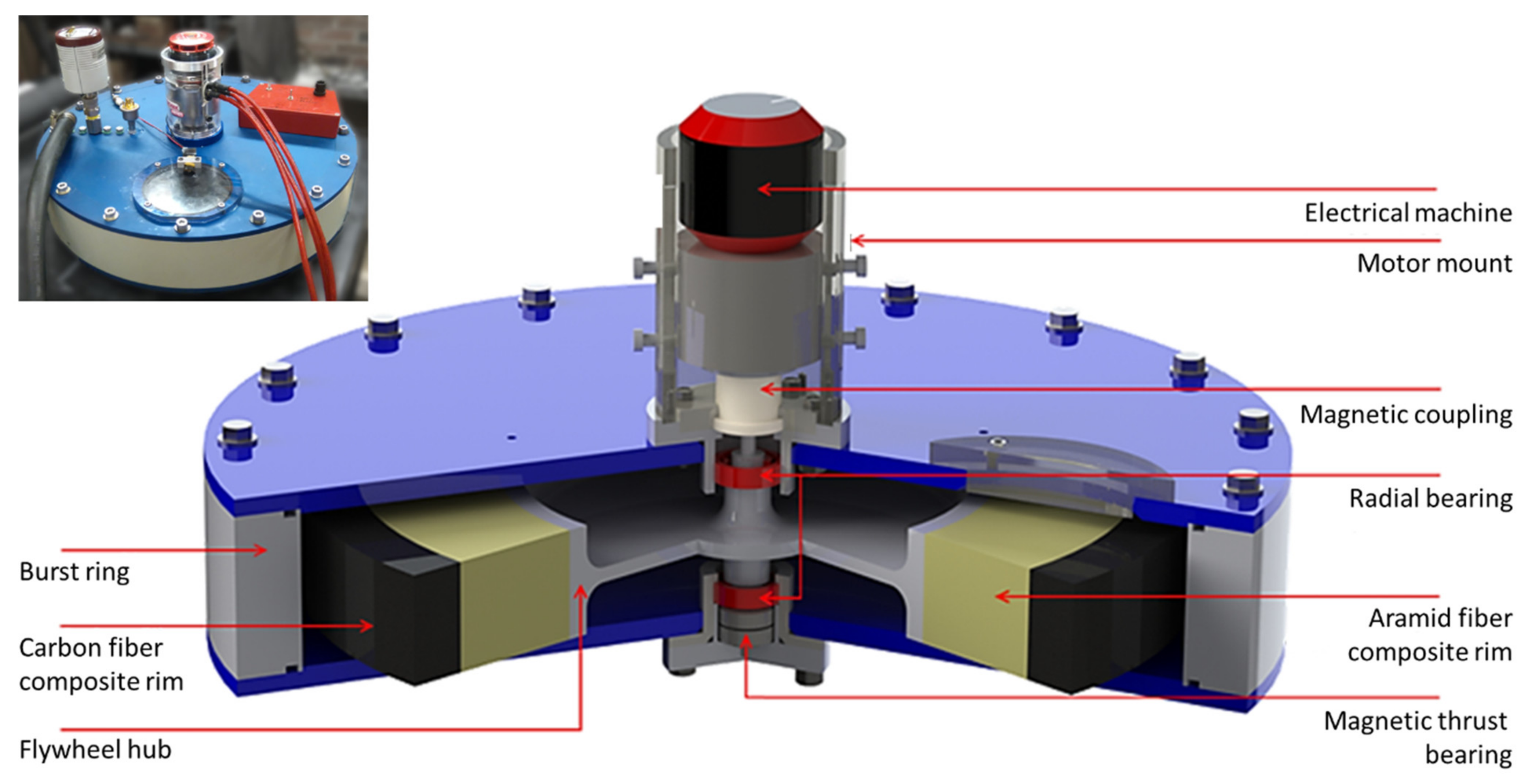
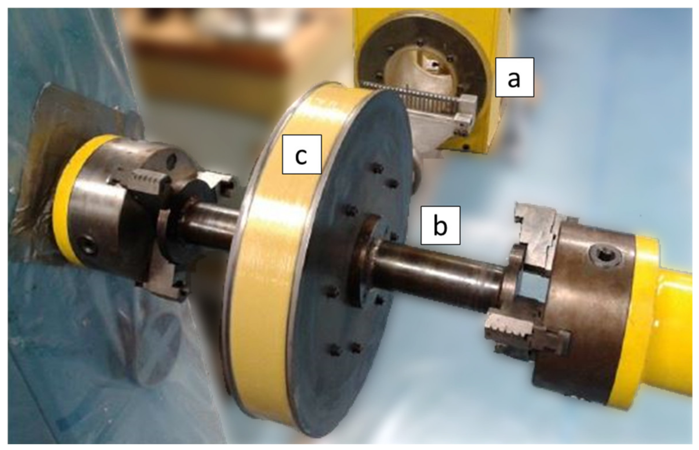
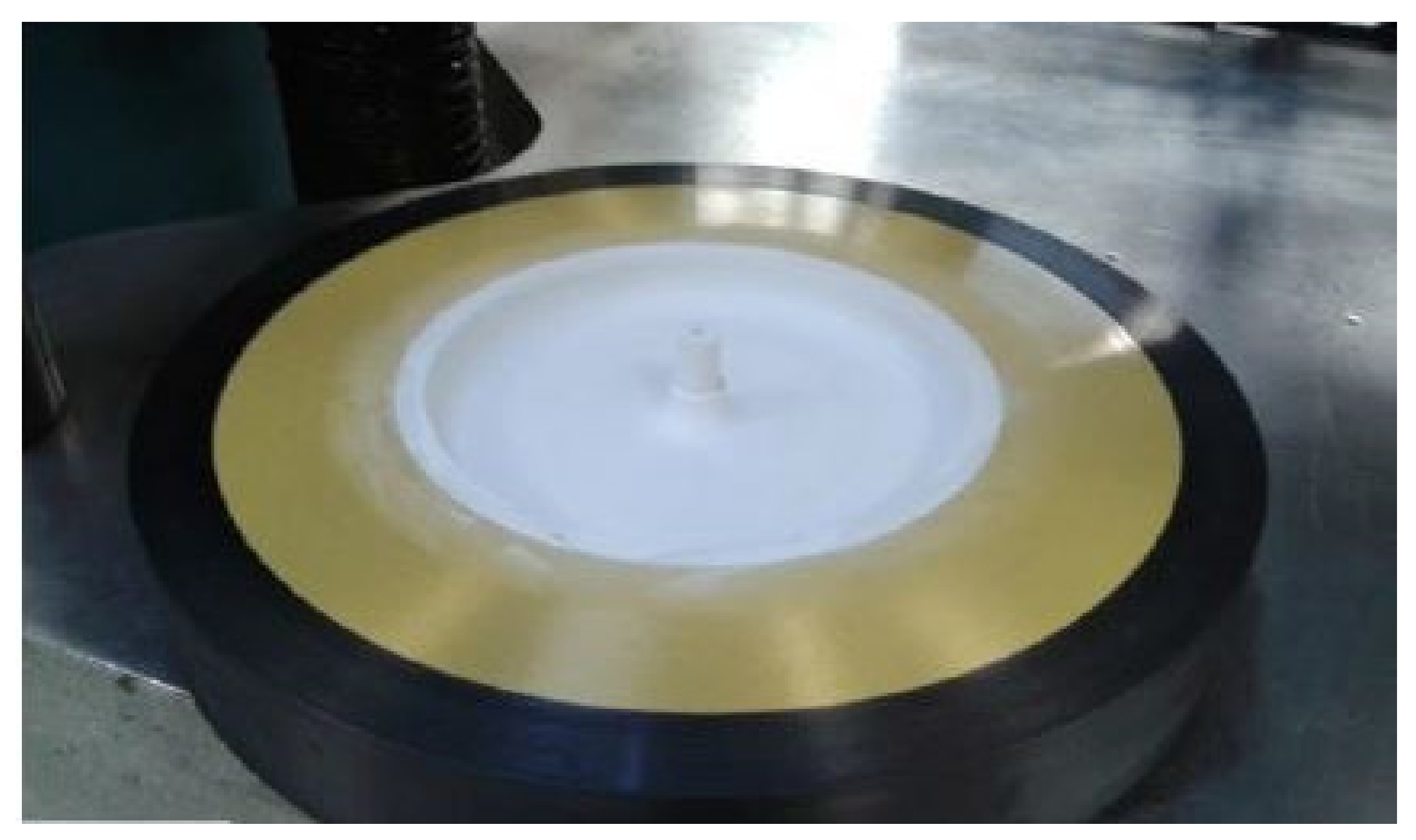
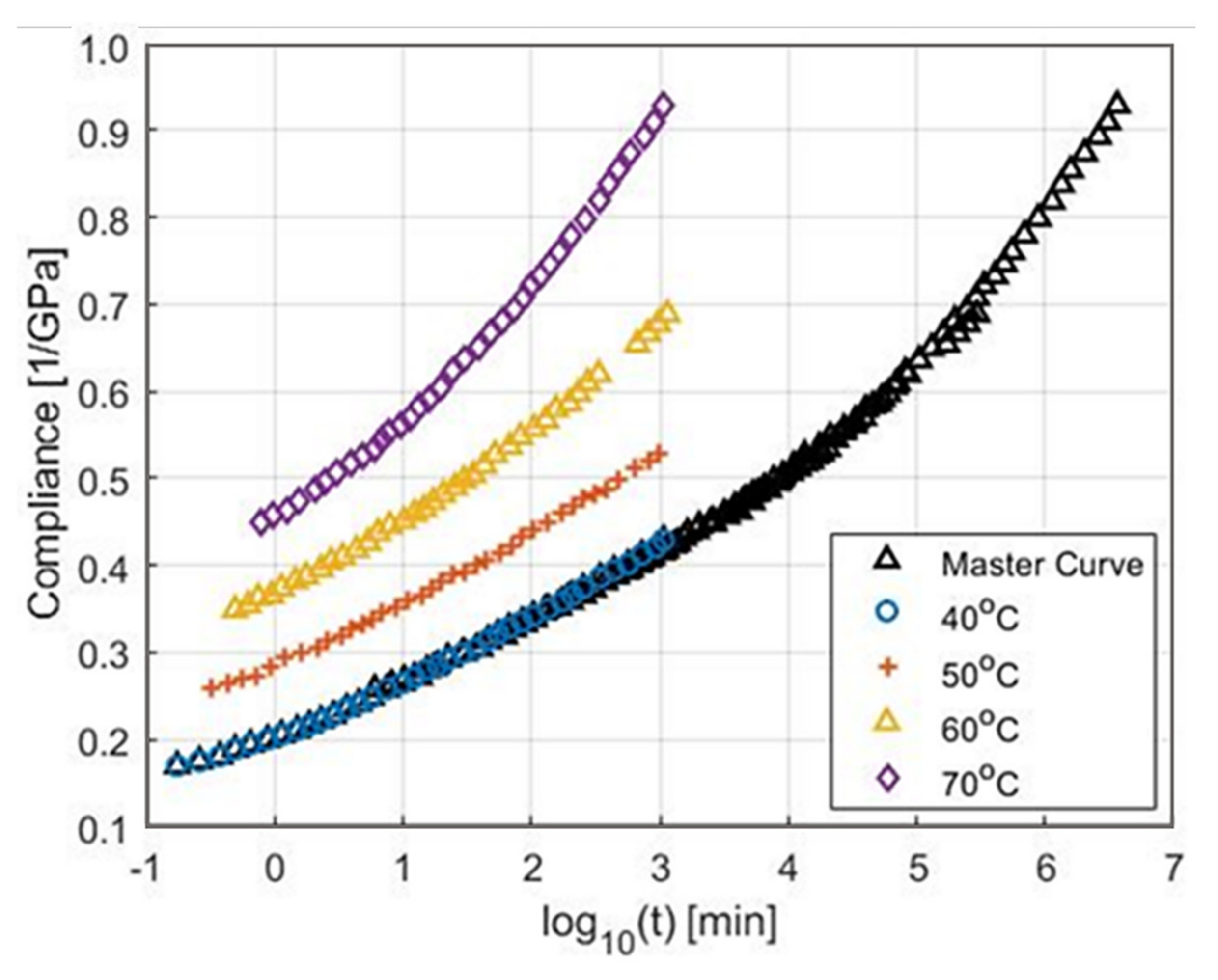
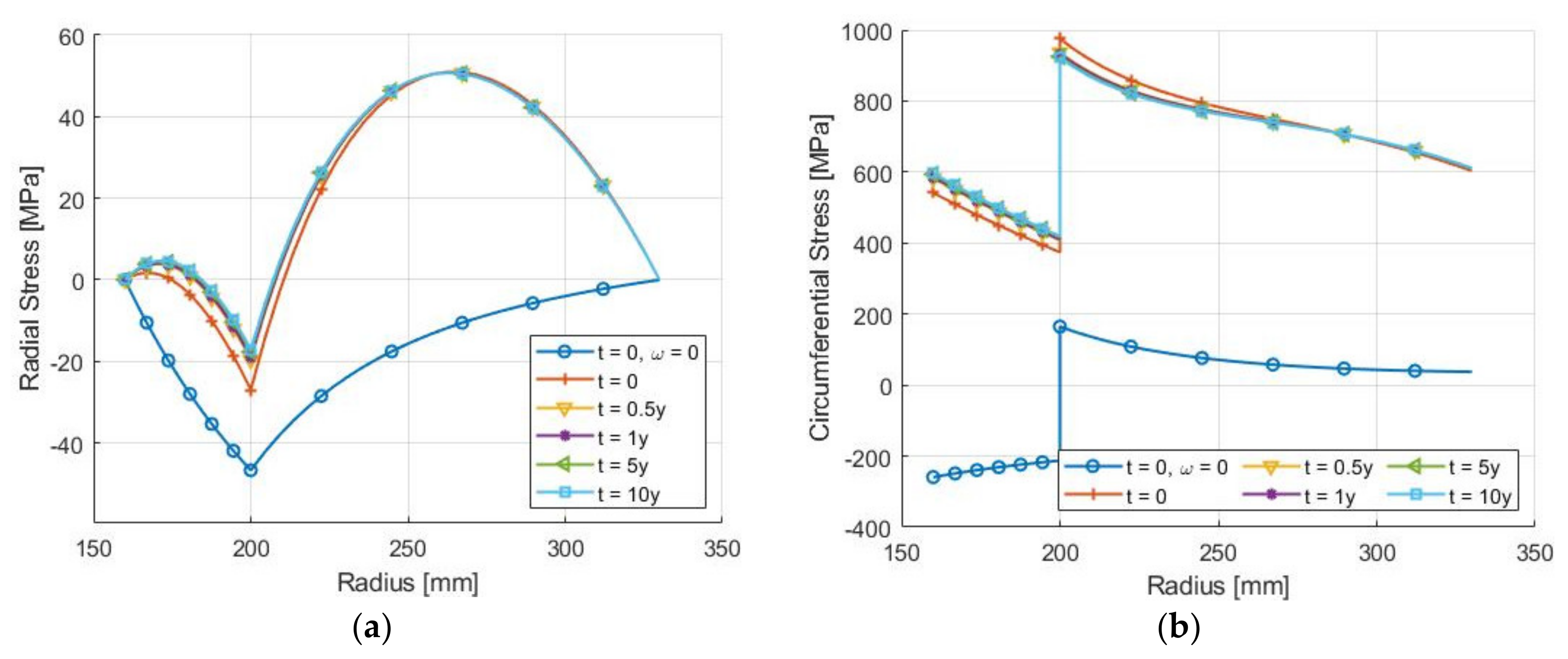
Table 1.
General range of FESS performance characteristics.
| Parameter | Value |
|---|---|
| Lifetime [years] | >20 [5] |
| Charge/discharge cycles | <107 [5] |
| Energy density [Wh/kg] | <130 [17] |
| Price [(USD)/kWh] | 400–6960 [5,17] |
| Power density [W/kg] | ~1000 [5] |
Table 2.
Shape factor values (k) for various flywheel rotor cross sections.
| Shape | Cross Section | k-Value |
|---|---|---|
| Laval disk |  | 1.00 |
| Laval disk real |  | 0.70–0.90 |
| Conical disk |  | 0.70–0.85 |
| Solid disk |  | 0.606 |
| Thin ring |  | 0.50 |
| Thick rim |  | 0.303 |
Publisher’s Note: MDPI stays neutral with regard to jurisdictional claims in published maps and institutional affiliations. |
© 2022 by the authors. Licensee MDPI, Basel, Switzerland. This article is an open access article distributed under the terms and conditions of the Creative Commons Attribution (CC BY) license (https://creativecommons.org/licenses/by/4.0/).
Share and Cite
MDPI and ACS Style
Skinner, M.; Mertiny, P. Energy Storage Flywheel Rotors—Mechanical Design. Encyclopedia 2022, 2, 301-324. https://0-doi-org.brum.beds.ac.uk/10.3390/encyclopedia2010019
AMA Style
Skinner M, Mertiny P. Energy Storage Flywheel Rotors—Mechanical Design. Encyclopedia. 2022; 2(1):301-324. https://0-doi-org.brum.beds.ac.uk/10.3390/encyclopedia2010019
Chicago/Turabian StyleSkinner, Miles, and Pierre Mertiny. 2022. "Energy Storage Flywheel Rotors—Mechanical Design" Encyclopedia 2, no. 1: 301-324. https://0-doi-org.brum.beds.ac.uk/10.3390/encyclopedia2010019