Scalable and Reliable Data Center Networks by Combining Source Routing and Automatic Labelling

 ,
,  ,
,  , and
, and
Abstract
:1. Introduction
2. Related Work
- Differently from most of the state of the art, it follows a distributed approach to maximize scalability and resilience.
- Packet forwarding follows a source-routing approach based on previously assigned labels, but no additional headers or fields are required, not even for network recovery upon failures.
- Thanks to the nature of its labels, routing tables are drastically reduced, independently of the active communication flows, and network recovery can be executed even on-the-fly (zero delay) in some scenarios.
- Labels are automatically assigned at startup and after any network change, granting auto-configuration.
- It is generalized and applicable to any hierarchical DCN, guaranteeing flexibility.
3. The eTorii DCN
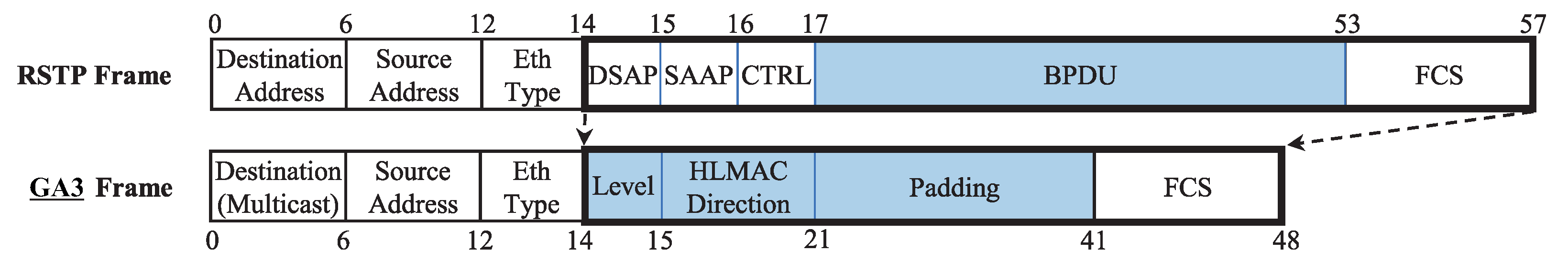
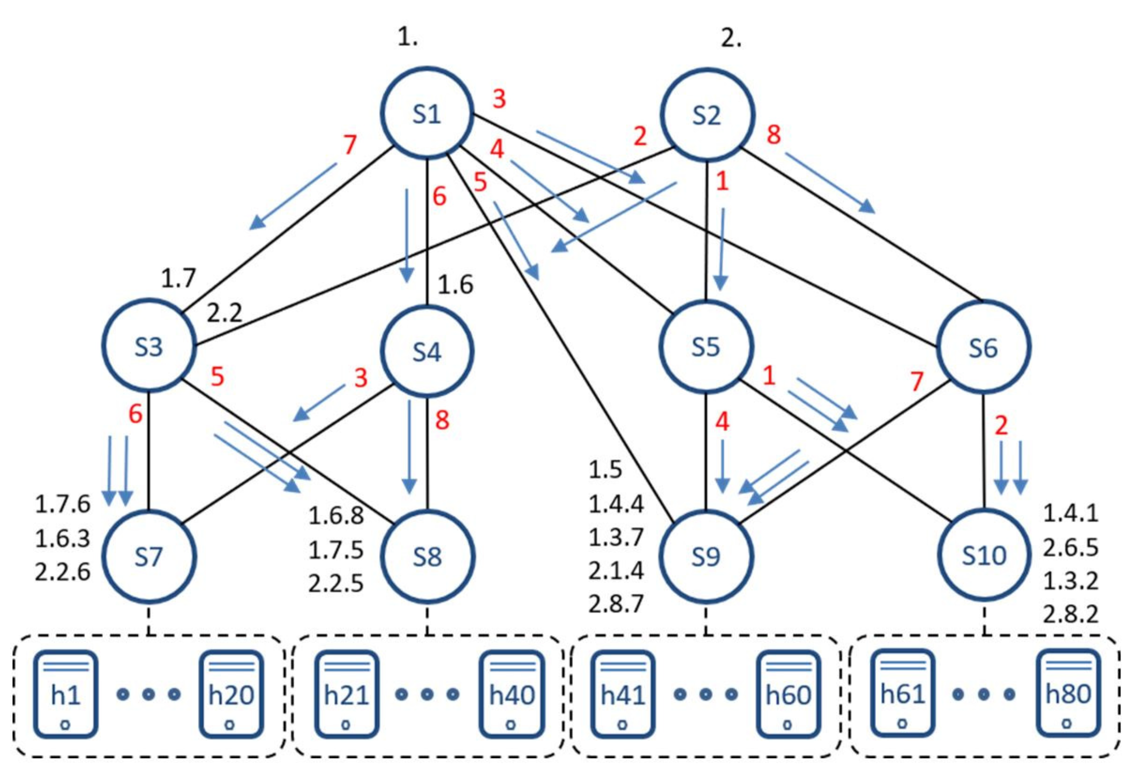
3.1. Auto-Configuration: Automatic Label Assignment Based on GA3
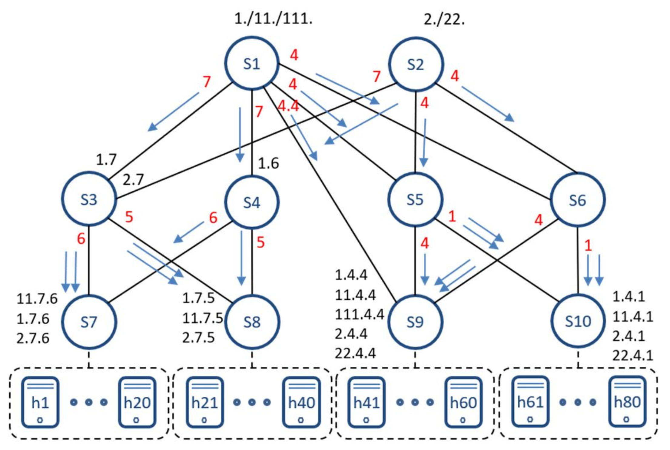
3.2. Scalability: Zero-Table Multiple-Path Routing
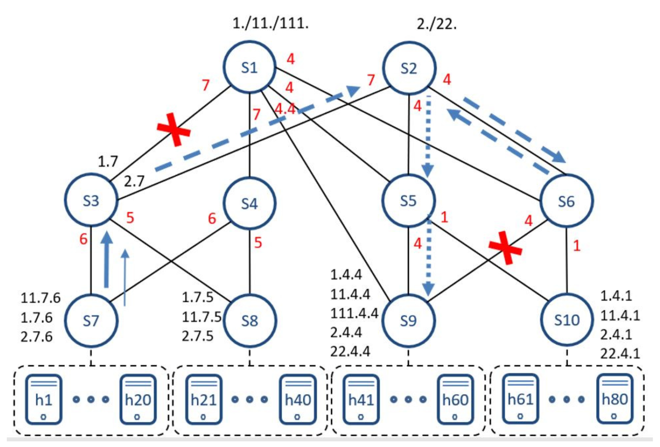
3.3. Resilience: On-the-Fly Path Repair
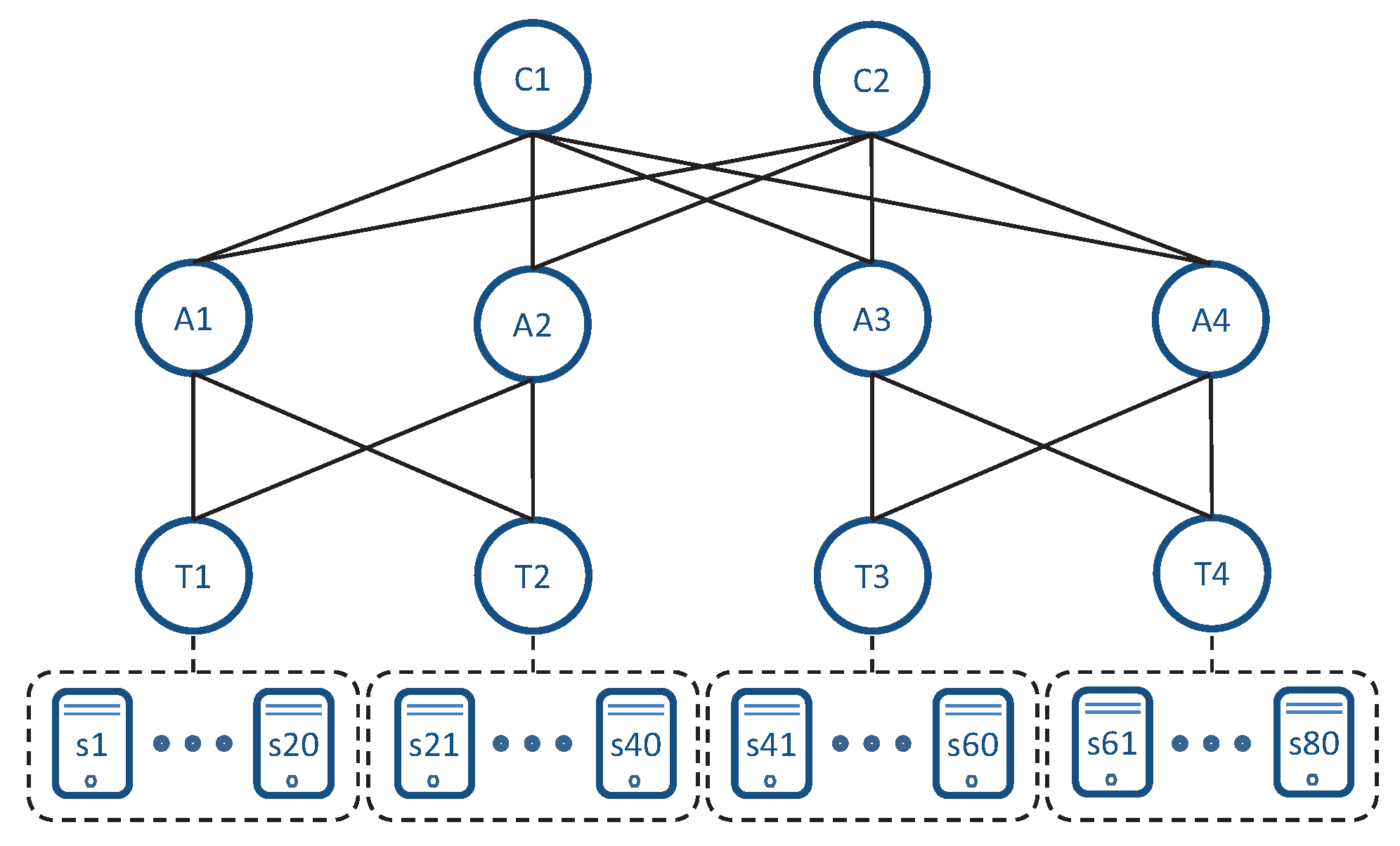
3.4. Flexibility: Generalization to Any Hierarchical DCN
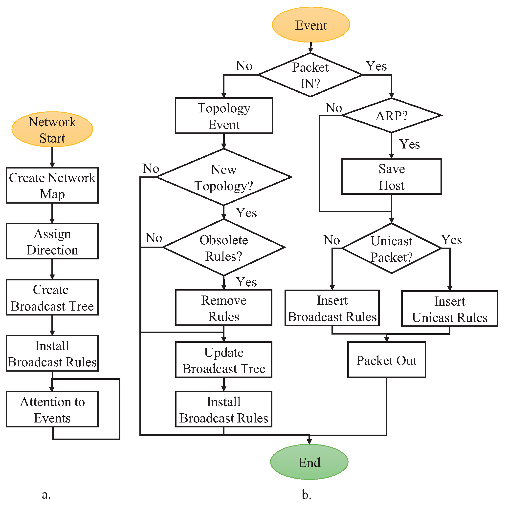
4. Implementation
4.1. Topology Discovery and HLMAC Address Assignment
4.2. Host Registration
4.3. Address Translation and Routing
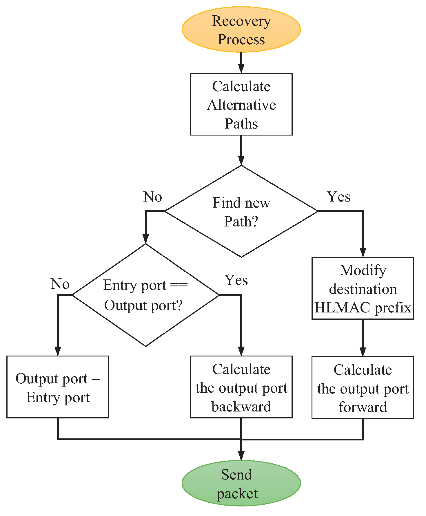
4.4. Recovery Mechanisms
5. Evaluation
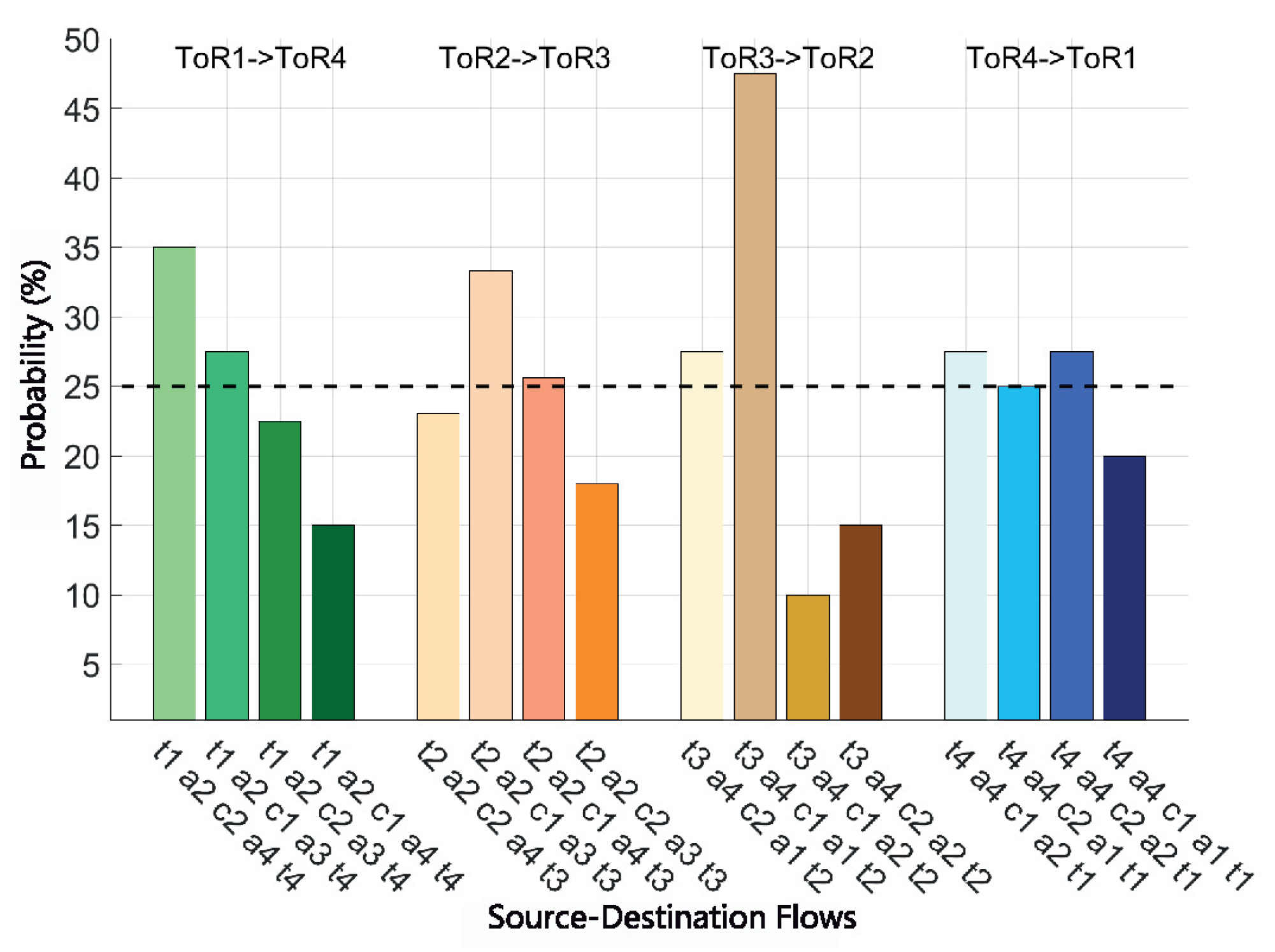
5.1. Test 1: Flow Routing Analysis
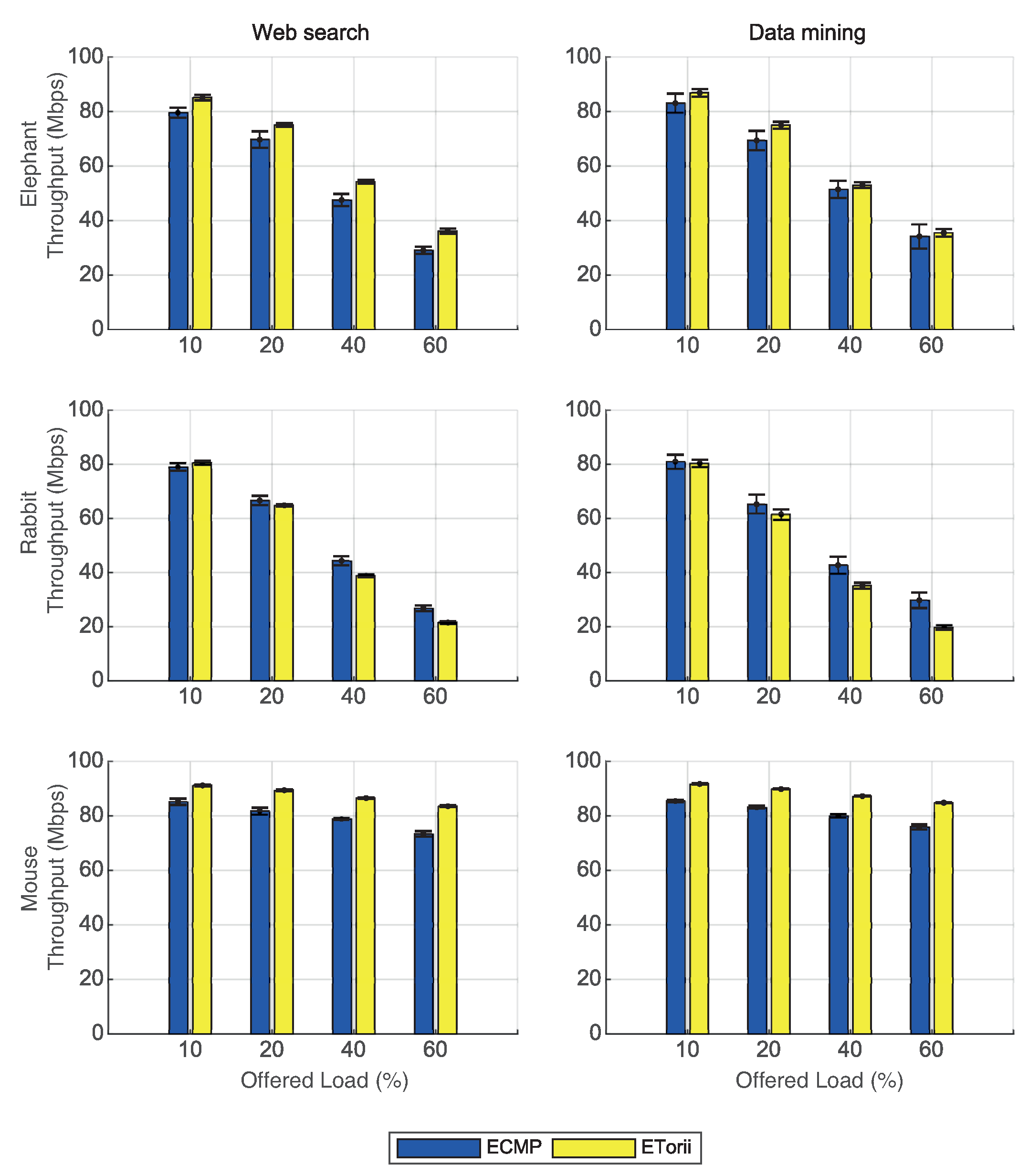
5.2. Test 2: Effective Throughput
6. Conclusions
Author Contributions
Funding
Conflicts of Interest
Abbreviations
| CDF | Cumulative Distribution Function |
| ECMP | Equal-Cost Multi-Path |
| HLMAC | Hierarchical Local MAC |
| LLDP | Link Layer Discovery Protocol |
| OVS | Open vSwitch |
| RSTP | Rapid Spanning Tree Protocol |
| SDN | Software-Defined Networking |
| ToR | Top-of-Rack |
References
- Milian, E.Z.; Spinola, M.M.; Carvalho, M.M. Risks and Uncertainties in Cloud Computing: Literature Review, Trends and Gaps. IEEE Lat. Am. Trans. 2017, 15, 349–357. [Google Scholar] [CrossRef]
- Mysore, R.N.; Pamboris, A.; Farrington, N.; Huang, N.; Miri, P.; Radhakrishnan, S.; Subramanya, V.; Vahdat, A. PortLand: A scalable fault-tolerant layer 2 data center network fabric. SIGCOMM Comput. Commun. Rev. 2009, 39, 39–50. [Google Scholar] [CrossRef]
- Greenberg, A.; Hamilton, J.R.; Jain, N.; Kandula, S.; Kim, C.; Lahiri, P.; Maltz, D.A.; Patel, P.; Sengupta, S. VL2: A scalable and flexible data center network. SIGCOMM Comput. Commun. Rev. 2009, 39, 51–62. [Google Scholar] [CrossRef]
- Al-Fares, M.; Loukissas, A.; Vahdat, A. A scalable, commodity data center network architecture. ACM SIGCOMM Comput. Commun. Rev. 2008, 38, 63–74. [Google Scholar] [CrossRef]
- Alexey Andreyev. Introducing Data Center Fabric, the Next-generation Facebook Data Center Network. 2014. Available online: https://code.facebook.com/posts/360346274145943/introducing-data-center-fabric-the-next-generation-facebook-data-center-network/ (accessed on 15 May 2021).
- Guo, C.; Lu, G.; Li, D.; Wu, H.; Zhang, X.; Shi, Y.; Tian, C.; Zhang, Y.; Lu, S. BCube: A High Performance, Server-centric Network Architecture for Modular Data Centers. SIGCOMM Comput. Commun. Rev. 2009, 39, 63–74. [Google Scholar] [CrossRef]
- Singla, A.; Hong, C.Y.; Popa, L.; Godfrey, P.B. Jellyfish: Networking data centers randomly. Presented at the 9th {USENIX} Symposium on Networked Systems Design and Implementation ({NSDI} 12), San Jose, CA, USA, 25–27 April 2013; pp. 225–238. [Google Scholar]
- Bhandarkar, S.; Behera, G.; Khan, K.A. Scalability Issues in Software Defined Network (SDN): A Survey. Adv. Comput. Sci. Inf. Technol. ACSIT 2015, 2, 81–85. [Google Scholar]
- Rojas, E.; Ibanez, G.; Gimenez-Guzman, J.M.; Rivera, D.; Azcorra, A. Torii: Multipath distributed Ethernet fabric protocol for data centres with zero-loss path repair. Trans. Emerg. Telecommun. Technol. 2015, 26, 179–194. [Google Scholar] [CrossRef]
- Rojas, E.; Alvarez-Horcajo, J.; Martinez-Yelmo, I.; Arco, J.M.; Carral, J.A. GA3: Scalable, distributed address assignment for dynamic data center networks. Ann. Telecommun. 2017, 72, 693–702. [Google Scholar] [CrossRef]
- Open Networking Foundation. Software-Defined Networking: The New Norm for Networks. Available online: https://opennetworking.org/sdn-resources/whitepapers/software-defined-networking-the-new-norm-for-networks/ (accessed on 15 May 2021).
- Kreutz, D.; Ramos, F.; Esteves Verissimo, P.; Esteve Rothenberg, C.; Azodolmolky, S.; Uhlig, S. Software-Defined Networking: A Comprehensive Survey. Proc. IEEE 2015, 103, 14–76. [Google Scholar] [CrossRef] [Green Version]
- Kempf, J.; Bellagamba, E.; Kern, A.; Jocha, D.; Takács, A.; Sköldström, P. Scalable fault management for OpenFlow. In Proceedings of the 2012 IEEE International Conference on Communications (ICC), Ottawa, ON, Canada, 10–15 June 2012; pp. 6606–6610. [Google Scholar]
- Wang, F.; Gao, L.; Shao, X.; Harai, H.; Fujikawa, K. Towards reliable and lightweight source switching for datacenter networks. In Proceedings of the 2017 IEEE Conference on Computer Communications, INFOCOM 2017, Atlanta, GA, USA, 1–4 May 2017; pp. 1–9. [Google Scholar] [CrossRef]
- Gonzalez-Diaz, S.; Marks, R.; Rojas, E.; de la Oliva, A.; Gazda, R. Stateless Flow-Zone Switching Using Software-Defined Addressing. IEEE Access 2021, 9, 68343–68365. [Google Scholar] [CrossRef]
- Sunshine, C.A. Source Routing in Computer Networks. SIGCOMM Comput. Commun. Rev. 1977, 7, 29–33. [Google Scholar] [CrossRef]
- Vanini, E.; Pan, R.; Alizadeh, M.; Taheri, P.; Edsall, T. Let It Flow: Resilient Asymmetric Load Balancing with Flowlet Switching. In Proceedings of the 14th USENIX Symposium on Networked Systems Design and Implementation (NSDI 17), Boston, MA, USA, 27–29 March 2017; USENIX Association: Boston, MA, USA, 2017; pp. 407–420. [Google Scholar]
- Liu, J.; Huang, J.; Lv, W.; Wang, J. APS: Adaptive Packet Spraying to Isolate Mix-flows in Data Center Network. IEEE Trans. Cloud Comput. 2020, 2020, 2985037. [Google Scholar] [CrossRef]
- Hu, J.; Huang, J.; Lv, W.; Zhou, Y.; Wang, J.; He, T. CAPS: Coding-Based Adaptive Packet Spraying to Reduce Flow Completion Time in Data Center. IEEE ACM Trans. Netw. 2019, 27, 2338–2353. [Google Scholar] [CrossRef]
- Huang, J.; Lyu, W.; Li, W.; Wang, J.; He, T. Mitigating Packet Reordering for Random Packet Spraying in Data Center Networks. IEEE ACM Trans. Netw. 2021, 29, 1183–1196. [Google Scholar] [CrossRef]
- Zhang, H.; Zhang, J.; Bai, W.; Chen, K.; Chowdhury, M. Resilient Datacenter Load Balancing in the Wild. In Proceedings of the Conference of the ACM Special Interest Group on Data Communication, SIGCOMM’17, Los Angeles, CA, USA, 21–25 August 2017; Association for Computing Machinery: New York, NY, USA, 2017; pp. 253–266. [Google Scholar] [CrossRef]
- Lopez-Pajares, D.; Alvarez-Horcajo, J.; Rojas, E.; Asadujjaman, A.S.M.; Martinez-Yelmo, I. Amaru: Plug Play Resilient In-Band Control for SDN. IEEE Access 2019, 7, 123202–123218. [Google Scholar] [CrossRef]
- Acharya, H.B.; Hamilton, J.; Shenoy, N. From Spanning Trees to Meshed Trees. In Proceedings of the 2020 International Conference on COMmunication Systems NETworkS (COMSNETS), Bangalore, India, 7–11 January 2020; pp. 391–395. [Google Scholar]
- IEEE Standard for Local and Metropolitan Area Networks: Overview and Architecture–Amendment 2: Local Medium Access Control (MAC) Address Usage; IEEE; Posted 25 Augest, 2017; Available online: https://0-standards-ieee-org.brum.beds.ac.uk/standard/802c-2017.html (accessed on 15 May 2021).
- Jin, X.; Farrington, N.; Rexford, J. Your Data Center Switch is Trying Too Hard. In Proceedings of the Symposium on SDN Research, SOSR’16, Santa Clara, CA, USA, 14 March 2016; ACM: New York, NY, USA, 2016; pp. 12:1–12:6. [Google Scholar] [CrossRef]
- Cholda, P. Network recovery, protection and restoration of optical, SONET-SDH, IP, and MPLS [book review]. IEEE Commun. Mag. 2005, 43, 12. [Google Scholar] [CrossRef]
- Nelakuditi, S.; Zhang, Z.L. On Selection of Paths for Multipath Routing. In Proceedings of the 9th International Workshop on Quality of Service, IWQoS’01, Karlsruhe, Germany, 6–8 June 2001; Springer: Berlin/Heidelberg, Germany, 2001; pp. 170–186. [Google Scholar]
- Raiciu, C.; Barre, S.; Pluntke, C.; Greenhalgh, A.; Wischik, D.; Handley, M. Improving Datacenter Performance and Robustness with Multipath TCP. SIGCOMM Comput. Commun. Rev. 2011, 41, 266–277. [Google Scholar] [CrossRef]
- Ryu SDN Framework. Available online: https://ryu-sdn.org/ (accessed on 15 May 2021).
- McKeown, N.; Anderson, T.; Balakrishnan, H.; Parulkar, G.; Peterson, L.; Rexford, J.; Shenker, S.; Turner, J. OpenFlow: Enabling innovation in campus networks. ACM SIGCOMM Comput. Commun. Rev. 2008, 38, 69–74. [Google Scholar] [CrossRef]
- Link-Layer Discovery Protocol IEEE 802.1 AB: Link Layer Discovery Protocol (LLDP). Available online: https://www.ieee802.org/1/files/public/docs2002/lldp-protocol-00.pdf (accessed on 15 May 2021).
- Pfaff, B.; Pettit, J.; Koponen, T.; Jackson, E.; Zhou, A.; Rajahalme, J.; Gross, J.; Wang, A.; Stringer, J.; Shelar, P.; et al. The Design and Implementation of Open vSwitch. In Proceedings of the 12th USENIX Symposium on Networked Systems Design and Implementation (NSDI 15), Oakland, CA, USA, 4–6 May 2015; USENIX Association: Oakland, CA, USA, 2015; pp. 117–130. [Google Scholar]
- Mininet. Available online: http://mininet.org/ (accessed on 15 May 2021).
- Singh, A.; Ong, J.; Agarwal, A.; Anderson, G.; Armistead, A.; Bannon, R.; Boving, S.; Desai, G.; Felderman, B.; Germano, P.; et al. Jupiter rising: A decade of clos topologies and centralized control in google’s datacenter network. ACM SIGCOMM Comput. Commun. Rev. 2015, 45, 183–197. [Google Scholar] [CrossRef] [Green Version]
- 802.1Qbp—Equal Cost Multiple Paths. Available online: https://www.ieee802.org/1/pages/802.1bp.html (accessed on 15 May 2021).
- Alizadeh, M.; Greenberg, A.; Maltz, D.A.; Padhye, J.; Patel, P.; Prabhakar, B.; Sengupta, S.; Sridharan, M. Data Center TCP (DCTCP). In Proceedings of the ACM SIGCOMM 2010 Conference, SIGCOMM’10, Melbourne, Australia, 1–30 November 2010; ACM: New York, NY, USA, 2010; pp. 63–74. [Google Scholar] [CrossRef]
- Alvarez-Horcajo, J.; Lopez-Pajares, D.; Arco, J.M.; Carral, J.A.; Martinez-Yelmo, I. TCP-path: Improving load balance by network exploration. In Proceedings of the 2017 IEEE 6th International Conference on Cloud Networking (CloudNet), Prague, Czech Republic, 25–27 September 2017; pp. 1–6. [Google Scholar] [CrossRef]
Short Biography of Authors
 | Elisa Rojas received her PhD in Information and Communication Technologies engineering from the University of Alcala, Spain, in 2013. As a postdoc, she worked in IMDEA Networks and, later on, as CTO of Telcaria Ideas S.L. She has participated in diverse projects funded by the EC, such as FP7-NetIDE or H2020-SUPERFLUIDITY. She currently works as an Assistant Professor in the University of Alcala where her current research interests encompass SDN, NFV, IoT routing, and high-performance Ethernet and data center networks. |
 | Joaquín Álvarez-Horcajo obtained their PhD in Information and Communication Technologies engineering from the University of Alcala in 2020. After having worked at Telefonica as a test engineer for COFRE and RIMA networks, he was awarded a grant for university professor training (FPU) at the University of Alcala. The areas of research where he has worked include Software Defined Networks (SDN), Internet protocols, and new generation protocols. At present, he is especially interested in topics related to advanced switches and SDN networks. He has participated in various competitive projects funded through the Community of Madrid plan, such as TIGRE5-CM and TAPIR-CM. |
 | Isaías Martínez-Yelmo received the Ph.D. degree in telematics from the Carlos III University of Madrid, Spain, in 2010. After working as a Postdoctoral Assistant with the Carlos III University of Madrid, he became and remains as a Teaching Assistant with the Automatics Department, Alcalá University, Spain. His research interests include peer-to-peer networks, content distribution networks, vehicular networks, NGN, and the Internet protocols. Nowadays, he is especially interested in advanced switching architectures, software-defined networks and P4. He has participated in various competitive research projects funded by the Madrid Regional Government (Medianet, Tigre5, TAPIR, IRIS), National projects (CIVTRAFF), and European projects (CONTENT, CARMEN, and so on). His research papers have been published in highimpact JCR indexed research journals, such as the IEEE Communications Magazine, Computer Communications, and Computer Networks, among others. He is currently Associate Editor in the Journal of Telecommunication Systems from Springer. In addition, he has been a Reviewer for high quality conferences (i.e., IEEE INFOCOM) and scientific journals (the IEEE Transactions on Vehicular Technology, Computer Communications, Computer Networks, the ACM Transactions on Multimedia Computing, and so on). He was a Technical Program Committee Member of IEEE ICON, from 2011 to 2013. |
 | José Manuel Arco received their Ph.D. in Telecommunications engineering from the University of Alcala, Spain, in 2002. He is Associate professor in the Automatica Department (Telematic Area) at the University of Alcalá in Spain since 2002. His current research interests encompass SDN/NFV, high performance and scalable Ethernet, Traffic Engineering and data center networks. He also teaches SDN/NFV and data center networks. He has participated on different competitive research projects from Madrid regional government, National and European. His research activity has been published in high impact JCR indexed research magazines, conferences and workshops on networking technologies. |
 | Miguel Briso-Montiano received their MSc in Electrical Engineering from the University of Alcala, Spain, in 2018. He is currently working at GMV as embedded software engineer for avionics and defence projects. His current research interests include data plane programmability with P4, SDN applications and IoT. |


| Parameter | Value |
|---|---|
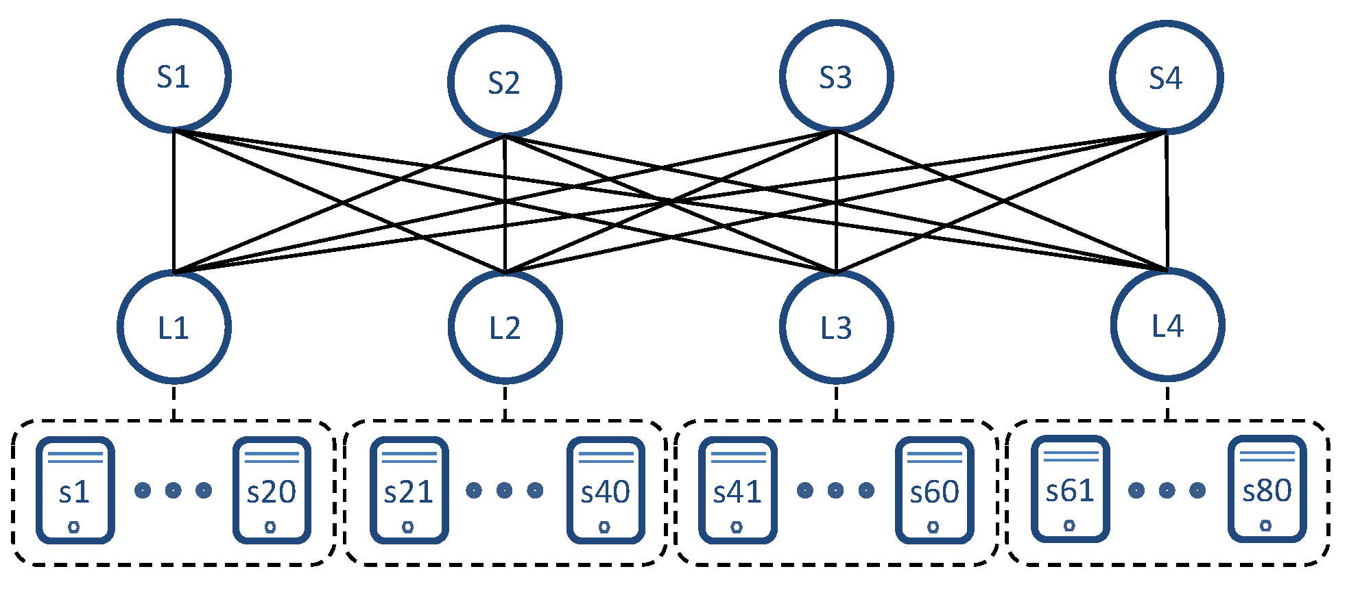
| Network topology | Spine-Leaf (4 × 4) |
| Hosts per Leaf | 20 |
| Flow distribution | Random Extra-Leaf |
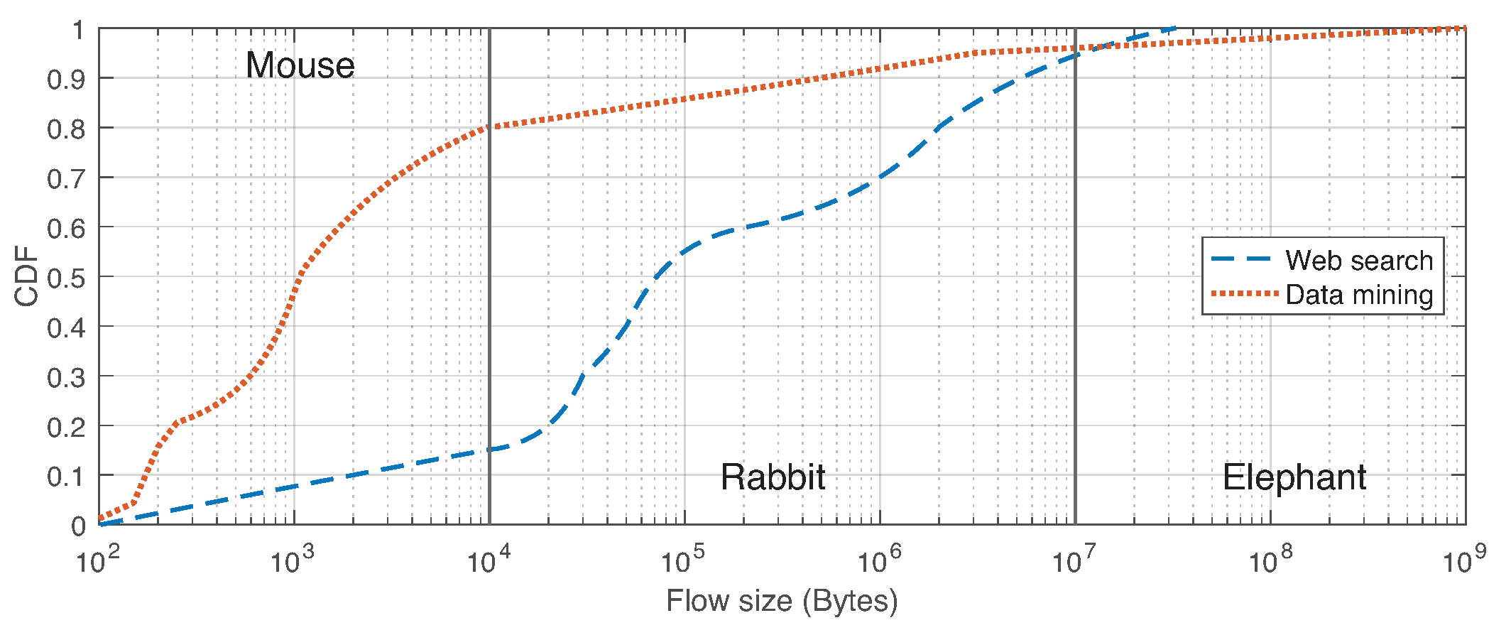
| Flow size distribution | Web Search [2] & Data Mining [36] |
| Network traffic load (%) | 10, 20, 40 y 60% |
| Link speed | 100 Mbps |
| Execution time | 1800 s |
| Transitory time | 800 s |
| Number of executions | 10 |
Publisher’s Note: MDPI stays neutral with regard to jurisdictional claims in published maps and institutional affiliations. |
© 2021 by the authors. Licensee MDPI, Basel, Switzerland. This article is an open access article distributed under the terms and conditions of the Creative Commons Attribution (CC BY) license (https://creativecommons.org/licenses/by/4.0/).
Share and Cite
Rojas, E.; Alvarez-Horcajo, J.; Martinez-Yelmo, I.; Arco, J.M.; Briso-Montiano, M. Scalable and Reliable Data Center Networks by Combining Source Routing and Automatic Labelling. Network 2021, 1, 11-27. https://0-doi-org.brum.beds.ac.uk/10.3390/network1010003
Rojas E, Alvarez-Horcajo J, Martinez-Yelmo I, Arco JM, Briso-Montiano M. Scalable and Reliable Data Center Networks by Combining Source Routing and Automatic Labelling. Network. 2021; 1(1):11-27. https://0-doi-org.brum.beds.ac.uk/10.3390/network1010003
Chicago/Turabian StyleRojas, Elisa, Joaquin Alvarez-Horcajo, Isaias Martinez-Yelmo, Jose M. Arco, and Miguel Briso-Montiano. 2021. "Scalable and Reliable Data Center Networks by Combining Source Routing and Automatic Labelling" Network 1, no. 1: 11-27. https://0-doi-org.brum.beds.ac.uk/10.3390/network1010003