1. Introduction
In recent years, the ever-increasing demand for smaller and faster electronic components has stimulated a lot of research in the development of suitable energy storage devices [
1,
2]. Energy storage is one of the key requirements for flexible devices in particular [
3]. Supercapacitors are considered to be promising charge storage devices owing to their fast charge/discharge rate and long cycle life [
4,
5]. Wire-shaped capacitors have shown various advantages in the development of lightweight, reconfigurable, and wearable electronics. Among the potential materials, carbon nanotube (CNT) fibers are promising candidates for wire-shaped electrodes owing to their remarkable mechanical properties, low weight, high conductivity, and excellent chemical stability [
6,
7,
8]. In CNT fibers, the one-dimensional structure of each individual CNT, with its high electronic conductivity, promotes rapid charge separation and transport [
9]. The outstanding potential of CNT fibers for various fiber-based devices has been demonstrated, including for e.g., supercapacitors [
10], solar cells [
11], actuators [
12], and biosensors [
13]. CNT fiber electrodes have also been applied for biocompatible implantable supercapacitors [
14], as well as for neurochemical monitoring [
15]. However, the electrical double-layer capacitance of CNT fiber alone is rather limited (~10–20 F/g) [
16] and is insufficient for commercial devices. In order to circumvent this bottleneck, doping [
17] or integration of pseudocapacitance materials (such as RuO
2 and MnO
2) into CNT fibers is beneficial and leads to a substantial improvement of the electrochemical performance of CNT fiber-based electrodes [
18]. Among the different pseudocapacitance materials, MnO
2 is particularly attractive for large-scale production due to its low cost, abundance, and high theoretical capacitance (1370 F/g). Nevertheless, MnO
2 shows drawbacks, such as low electronic conductivity, poor rate performance, and limited cycling ability [
19]. Therefore, the combination of MnO
2 and CNT fiber represents a promising alternative leading to enhanced supercapacitor performance.
Different methods have been developed to fabricate CNT–MnO
2 hybrid composites [
20]. One of the most widely reported methods is electrochemical deposition: Ren et al. [
21] reported a CNT–MnO
2 composite fiber (4.1 wt.% MnO
2) with a capacitance of 0.019 mF/cm. A CNT–MnO
2 yarn supercapacitor with a capacitance of 25.4 F/cm
3 at 10 mV/s has also been reported by Choi et al. [
22]. Nevertheless, due to the hydrophobicity of CNT fibers, it is difficult for an aqueous solution to enter the pores inside CNT fibers. As a result, the deposition of MnO
2 is mostly restricted to the surface of CNT fibers, which leads to a limited loading of MnO
2 and hence to poor pseudocapacitance. In addition, the resulting deposit also critically depends on the condition of electrochemical deposition [
23]. In order to overcome these difficulties, in situ routes have been explored. For example, Xu et al. [
24] employed the reaction between ethanol and KMnO
4 solution to deposit MnO
2 nanoparticles on CNT fibers, and Cui et al. [
25] used Mn(CH
3COO)
2·4H
2O/ethanol solution to decorate CNT arrays with Mn
3O
4 nanoparticles. Nonetheless, these CNT–manganese oxide composites still lack homogeneous distribution of decorating nanoparticles and suffer from low capacitance. So far, detailed studies of CNT wire electrodes after deposition of manganese oxide are still rare, especially those that report their surface and mechanical properties. Such studies could move the development of CNT–manganese oxide composite electrodes a significant step forward to wearable devices.
In this study, we successfully fabricated flexible CNT–MnO
2 fibers by spontaneous deposition of MnO
2 on CNT fibers using a direct redox reaction between CNTs and KMnO
4 aqueous solution with various concentrations of KMnO
4 and reaction times, which yielded different but homogeneous MnO
2 loadings (mass ratio of MnO
2/CNT fiber). The wettability measurement showed that the fabricated CNT–MnO
2 fiber was hydrophilic, which is crucial for the electrochemical performance of supercapacitors [
26]. Surface energy components of CNT–MnO
2 were determined by using the acid–base model [
27] and physical adhesion between CNT–MnO
2 and two common polymer electrolyte matrices (PVA and PVDF) was predicted. This prediction provided the criteria for selecting PVA as the more appropriate polymer electrolyte matrix for the fabrication of the supercapacitor. This systematic study also demonstrates that various aspects of the fabrication process that have so far not been sufficiently considered in the literature have a significant impact on the surface and mechanical properties of CNT–MnO
2 fibers and highlight that particular attention is required when preparing the fibers and supercapacitors.
A wire-shaped supercapacitor was fabricated by assembling two aligned CNT–MnO
2 fibers and showed a specific capacitance of 17.1 F/g (or 621.8 µF/cm) at 1 A/g coupled with good cycling stability (100% capacitance retention after 1200 cycles). Together with a tensile strength comparable with that of commonly used fibers (e.g., cotton [
28]), these results demonstrate the promising potential of wire-shaped supercapacitors composed of CNT–MnO
2 fibers for use as energy storage devices integrated into an electronic circuit for future wearable and deformable electronics.
2. Results and Discussion
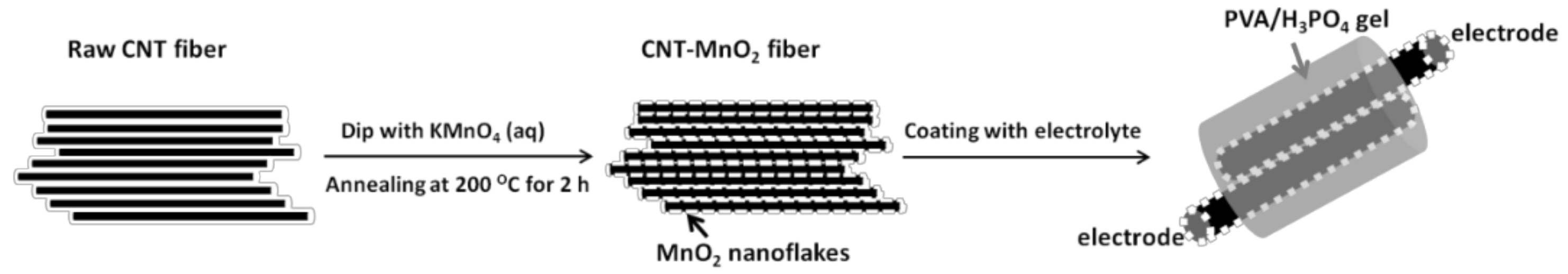
For the fabrication of the wire-shaped supercapacitors, CNT fibers were produced through dry-spinning from a CNT carpet grown on Si. Details about CNT growth and the dry-spinning procedure of CNT fibers can be found in our previous work [
29]. A schematic overview of the fabrication procedure of the CNT fiber-based supercapacitor is given in
Figure 1.
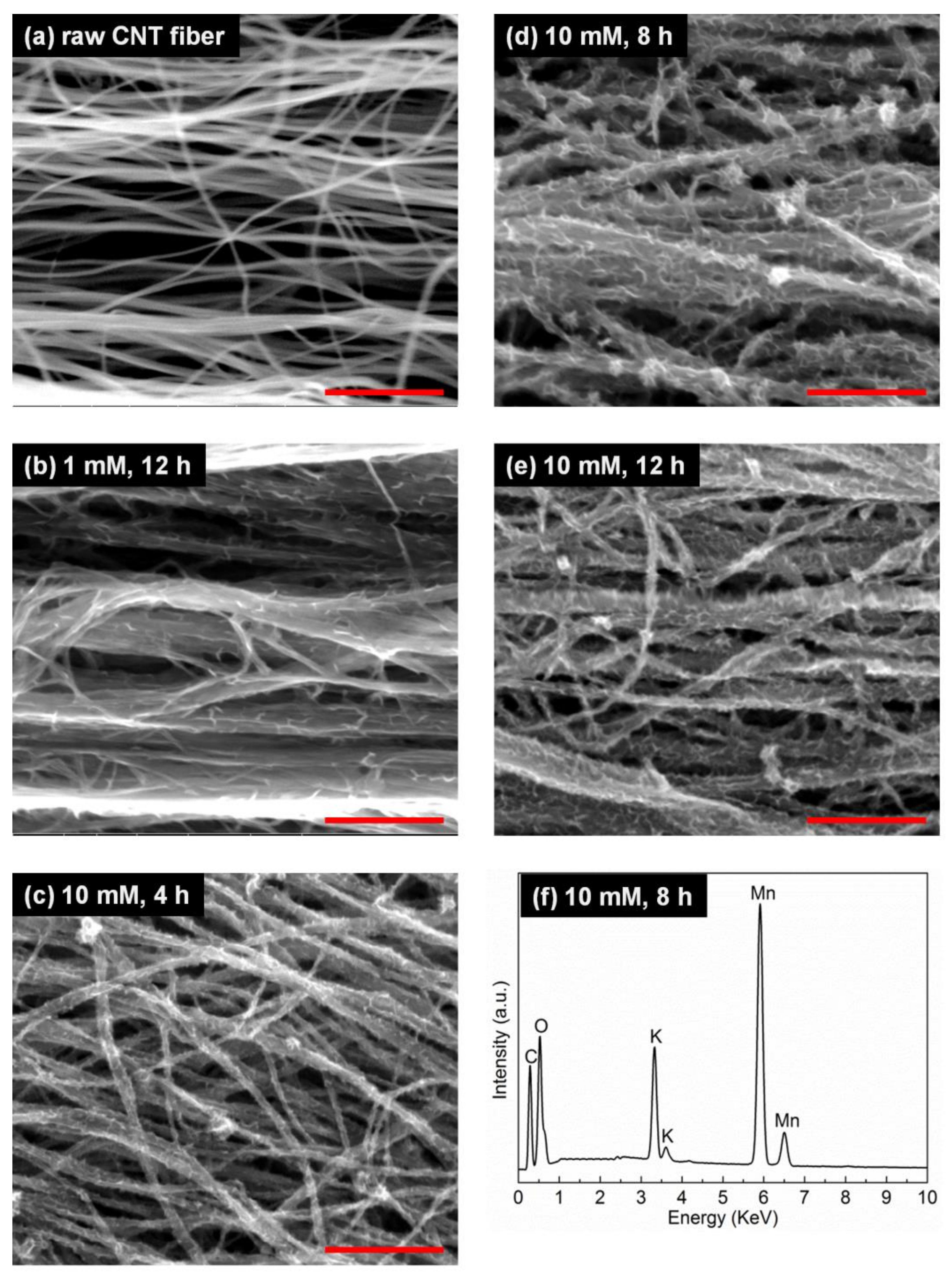
Figure 2 shows the morphology and chemical compositions of the fibers investigated by scanning electron microscopy (SEM) and energy dispersive x-ray spectroscopy (EDS). The raw CNT fiber consisted of CNTs clustered to strands with an average diameter of 50 nm and with large gaps between individual strands, due to the fact that the fiber was not densified. Their surfaces were clean and smooth. After the reaction with KMnO
4, the surface of the CNT strands appeared serrated, with decorated nanoflakes (
Figure 2b–e). With increasing KMnO
4 concentration (
Figure 2b,e) or reaction time (
Figure 2c–e), the amount of MnO
2 nanoflakes deposited on the fiber surface increased gradually. The weight percentage of MnO
2 in the CNT–MnO
2 composite reached 85.7% for the CNT–MnO
2 fiber (10, 12). The MnO
2 nanoflakes were homogeneously distributed along the CNT strands and were connected to each other, which significantly increased the specific surface area of the fiber and was beneficial for improving the electrochemical performance [
30].
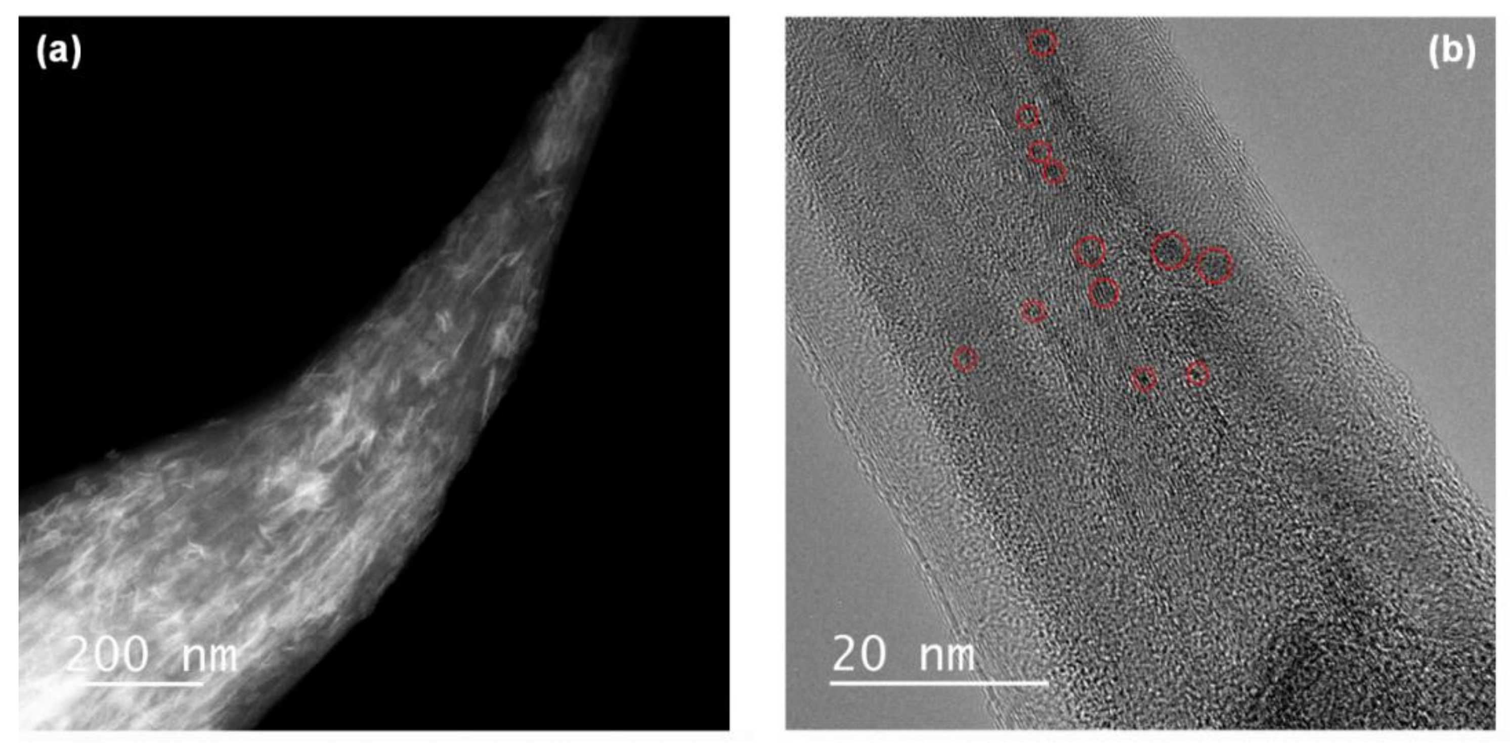
Transmission electron microscopy (TEM) and scanning TEM (STEM) images confirmed the presence of MnO
2 nanoparticles while the original shape of the raw CNT fiber was retained. The fiber was homogeneously covered with MnO
2 nanoflakes, which appeared as bright compared to the dark-appearing CNTs in the annular dark field (ADF) STEM image in
Figure 3a. These results were in agreement with the SEM results shown in
Figure 2d. The size of the MnO
2 nanoflakes can be estimated to be approximately 2–3 nm, as revealed by the high-resolution TEM image in
Figure 3b. These small MnO
2 flakes are particularly favorable as they can shorten the ion-diffusion length during the electrochemical reaction (compared to bulk MnO
2), facilitating full utilization of the capacitance of MnO
2.
It can be noted that the volume of the CNT fibers was reduced after reaction with KMnO
4 solution and annealing at 200 °C. This shrinkage was caused by the elastocapillary aggregation of CNT strands and suggests the effective penetration of KMnO
4 solution between the CNT strands and the effective wetting of the CNT surfaces [
31], which also explains the homogeneous distribution of MnO
2 flakes observed by SEM and STEM. As can be seen in
Figure 2b–e, some of the CNT strands clustered together into larger ones, but large gaps between strands remained after the reaction, which are beneficial for electrolyte ion transportation [
25]. In addition, with the highest MnO
2 loading (
Figure 2e), significant charging effects were noticed during SEM observations, indicating a reduced electronic conductivity. This was mainly a result of the low conductivity of the manganese oxide species densely decorating the CNT surfaces. The EDS results shown in
Figure 2f reflect the chemical composition of the CNT–MnO
2 fiber (10, 8), with the clear appearance of C, O, Mn, and K peaks confirming the presence of manganese oxides. The peak corresponding to K could originate from KMnO
4 forming residual K
2CO
3 on the fibers [
28].
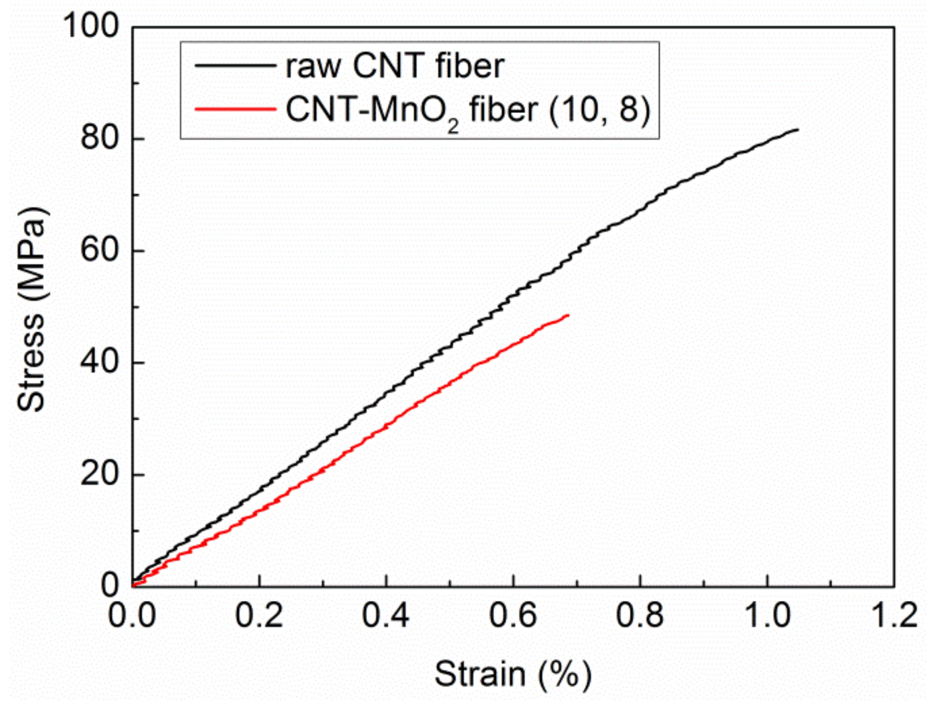
Another observation is that the fiber became more fragile with increasing KMnO
4 concentration and reaction time. This can be attributed to the deteriorated crystalline structure of CNTs after being exposed to KMnO
4 [
32]. For instance, CNT–MnO
2 fiber (10, 12), with a 12 h reaction time, became very fragile and difficult to handle. Therefore, the reaction time was limited to a maximum of 12 h. Stress–strain curves of the raw CNT fibers and CNT–MnO
2 fiber (10, 8) in
Figure 4 confirmed this trend. The strain-to-failure and strength were strongly affected by the KMnO
4 treatment. The 8 h treatment led to about 50% degradation in strength, indicating that the graphitic structure of CNTs is strongly affected by KMnO
4.
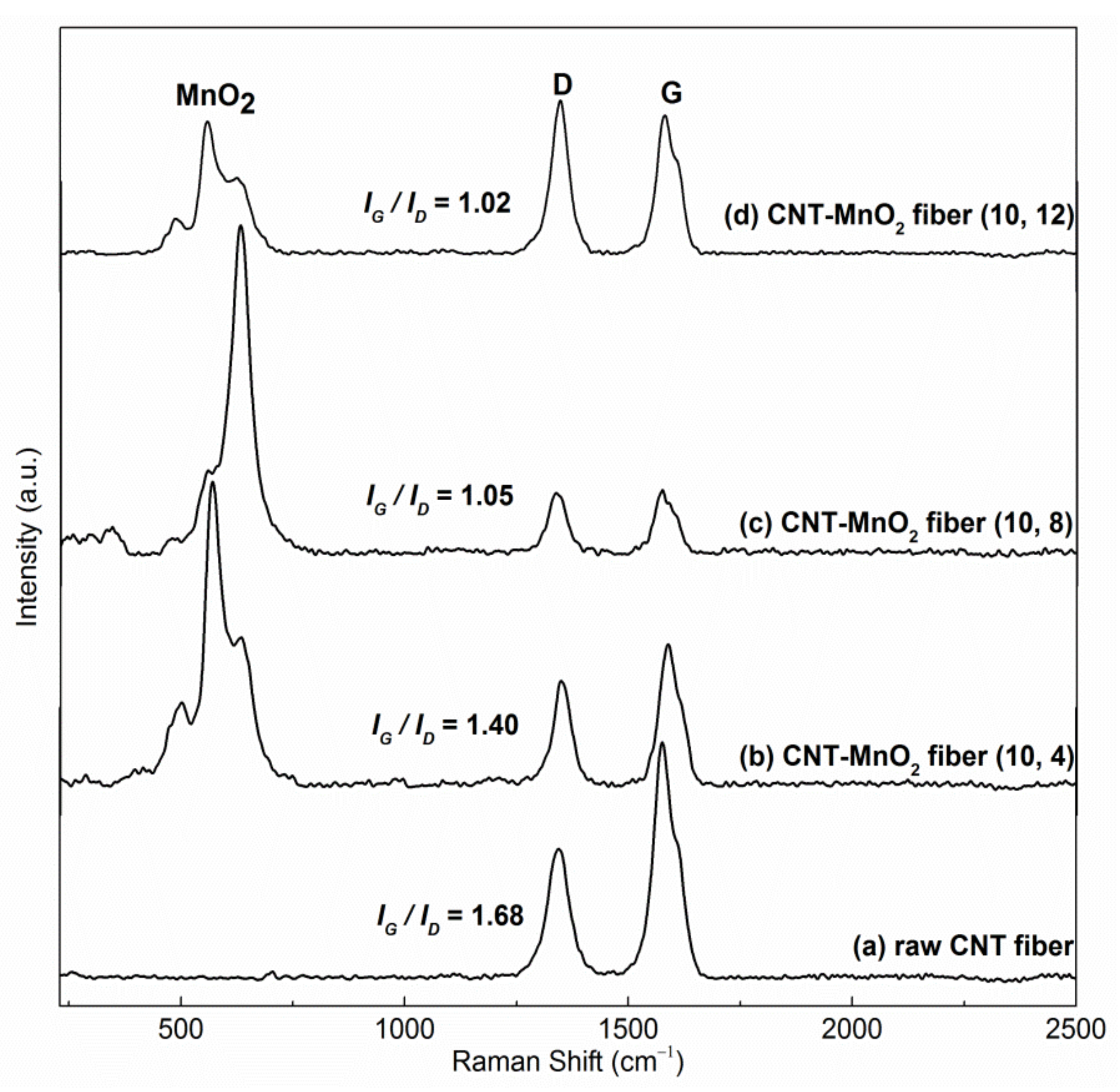
Figure 5b–d shows Raman spectra taken from CNT–MnO
2 fibers produced with 10 mM KMnO
4 with 4 h, 8 h, and 12 h reaction times. The raw CNT fiber was used as a reference (
Figure 5a). All spectra show a clear D-band at ~1350 cm
−1 and a G-band at ~1585 cm
−1, which correspond to disordered and graphitized carbon bonding in CNTs, respectively. The ratio of intensities of the G- and D-bands (
IG/ID) can be regarded as a measure of the crystalline order/disorder of CNTs [
33]. Among the tested samples, the raw CNT fiber showed the highest G to D ratio (
IG/ID = 1.68). This value decreased with increasing reaction time (
IG/ID = 1.48, 1.05, and 1.02 for 4 h, 8 h, and 12 h reactions, respectively), indicating a progressive degradation of the CNT crystalline structure in the CNT–MnO
2 fibers. This was because carbon, acting as a reductant, was being consumed during the reaction with KMnO
4 [
34,
35]. As a result, more defective CNTs were obtained with longer reaction times.
For CNT–MnO
2 fibers, three major features originating from MnO
2 can be recognized at ~500, 569, and 632 cm
−1 (
Figure 5b–d). The band at 632 cm
−1 was due to the symmetrical Mn–O vibrations of the MnO
6 groups, and the band located at 569 cm
−1 can be attributed to the displacement of the oxygen atoms relative to the manganese atoms along the octahedral chains [
28,
36].
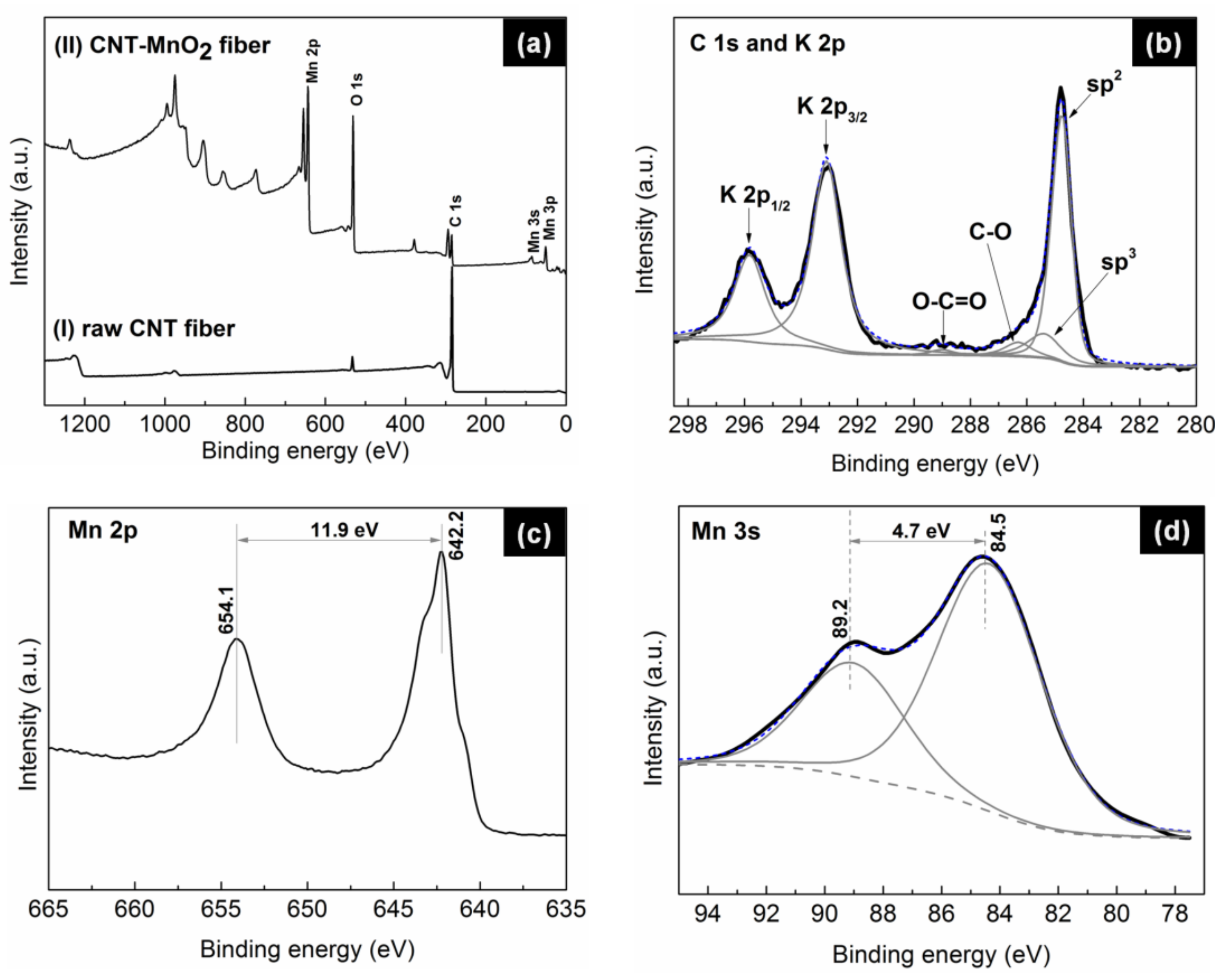
XPS measurements, undertaken to investigate the chemical composition of the fibers (
Figure 6), revealed that the carbon-to-oxygen ratio (C/O) significantly decreased from 10.1 for the raw CNT fiber to 0.19 for the CNT–MnO
2 composite fiber, implying the formation of metal oxides on the CNT surface.
Figure 6b shows the deconvoluted high-resolution C 1 s spectrum from CNT–MnO
2 fibers. The position and concentration of the fitted peaks are summarized in
Table 1. It can be seen that the signal of the π–π
* shake-up feature totally disappeared in the CNT–MnO
2 fiber. This observation indicates the formation of a thick MnO
2 layer on the top of the CNT fiber [
37]. The ratio of sp
2 and sp
3 concentrations was 4.9%, approximately two times smaller than that of the raw CNT fiber (9.3%). This decrease was in agreement with the observed loss of mechanical strength (
Figure 4) and the observed decrease of the G to D ratio of the Raman peak intensities (
Figure 5b–d). This observation also explains the reduced electronic conductivity of the composite fiber [
38].
The oxidation state of the produced manganese oxide was characterized by analyzing the Mn 2p and Mn 3 s peaks in detail. The binding-energy separation between the two Mn 2p doublet peaks was 11.9 eV (
Figure 6c), which closely matches the reported energy separation of MnO
2 [
39]. The analysis of the Mn 3 s peak led to the same conclusion: the doublet Mn 3 s peaks were caused by parallel spin coupling between electrons in the 3 s and 3d orbitals [
25]. It has been proven that the 3 s peak energy separation is related to the oxidation states of Mn [
18]. As can be seen from
Figure 6d, the binding-energy separation between the two Mn 3 s doublet peaks was 4.7 eV, further suggesting that the manganese oxides were in the form of MnO
2.
For the assembled supercapacitor, CNT–MnO
2 fiber (10, 8) was used for the electrodes. As a good adhesion between the electrodes and the polymer electrolyte is of paramount importance for the supercapacitor performance, the wettability of the produced CNT–MnO
2 fiber (10, 8) was tested with the tensiometric method. Details of the latter can be found in our previous work [
29]. Interestingly, in this investigation, it was found that the CNT–MnO
2 fiber was hydrophilic. By using the Cassie–Baxter model, equilibrium contact angles of a solid CNT–MnO
2 fiber with the three test liquids (deionized water (DW), ethylene glycol (EG), and diidomethane (DIO)) were predicted, and the results are listed in
Table 2. We previously reported a static water contact angle of 91° for CNT fiber [
29], and Dubal et al. [
40] reported that birnessite MnO
2 film is hydrophilic with a static water contact angle of 21°. Thus, the hydrophilicity of the CNT–MnO
2 fiber should be attributed to the decorating MnO
2 nanoflakes rather than to CNTs. This hydrophilic property is strongly favorable for aqueous electrolyte (e.g., Na
2SO
4) ion transportation, allowing the electrolyte to access the active materials inside the fibers.
The surface energy components of CNT–MnO
2 were calculated using the acid–base theory [
41]. As can be seen in
Table 3, the total surface tension of CNT–MnO
2 (42.49 ± 2.32 mJ/m
2) was larger than that of CNT (36.81 ± 2.59 mJ/m
2), as was the basic energy component. This difference could have been caused by the addition of MnO
2. Wetting parameters for CNT–MnO
2 and common matrices for polymer electrolytes (PVA and PVDF) are listed in
Table 4 (the surface energy components of PVDF were reported in our previous study [
42] and the values for PVA were found in the literature, without standard deviation mentioned [
43]). For both polymers, the spreading coefficient
S significantly increases compared to that for CNT, which implies that spontaneous wetting of CNT–MnO
2 is favored. PVA is more promising for achieving a better adhesion to CNT–MnO
2, owing to its high
Wa and Δ
F values. This is due to the fact that PVA has a similar
γLW to that of CNT–MnO
2. As the adhesion between the electrodes and the polymer electrolyte plays a crucial role in the performance of the supercapacitor, we chose PVA as the matrix polymer electrolyte.
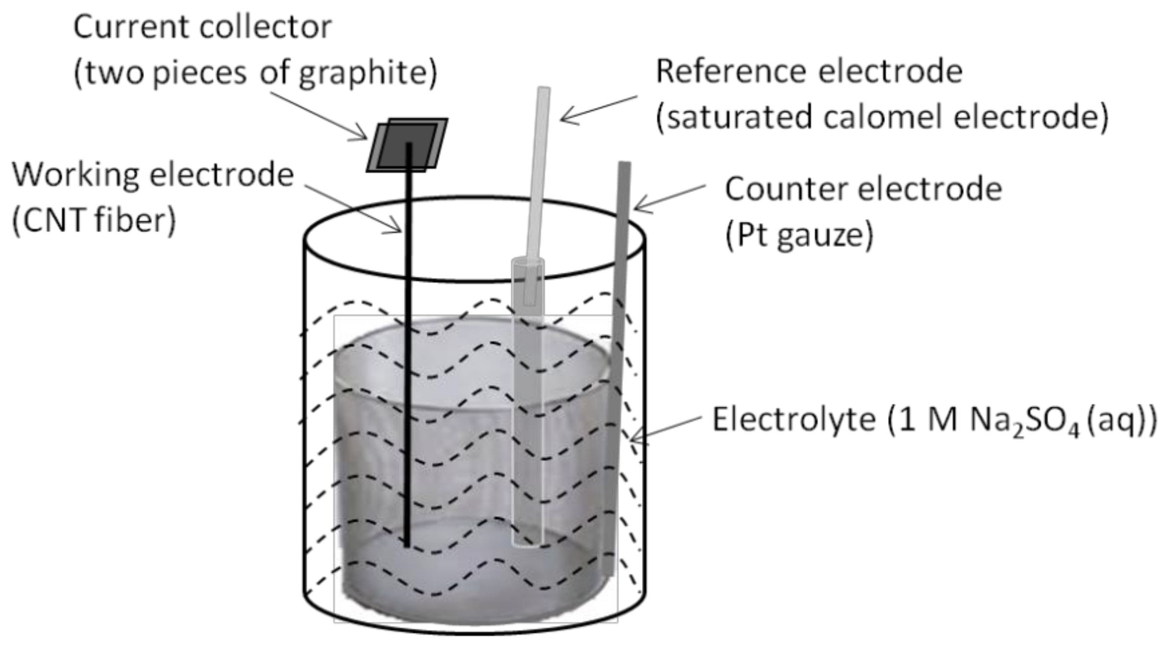
To test the electrochemical performance, a three-electrode cell configuration was employed by using CNT or CNT–MnO
2 fibers for the working electrode (
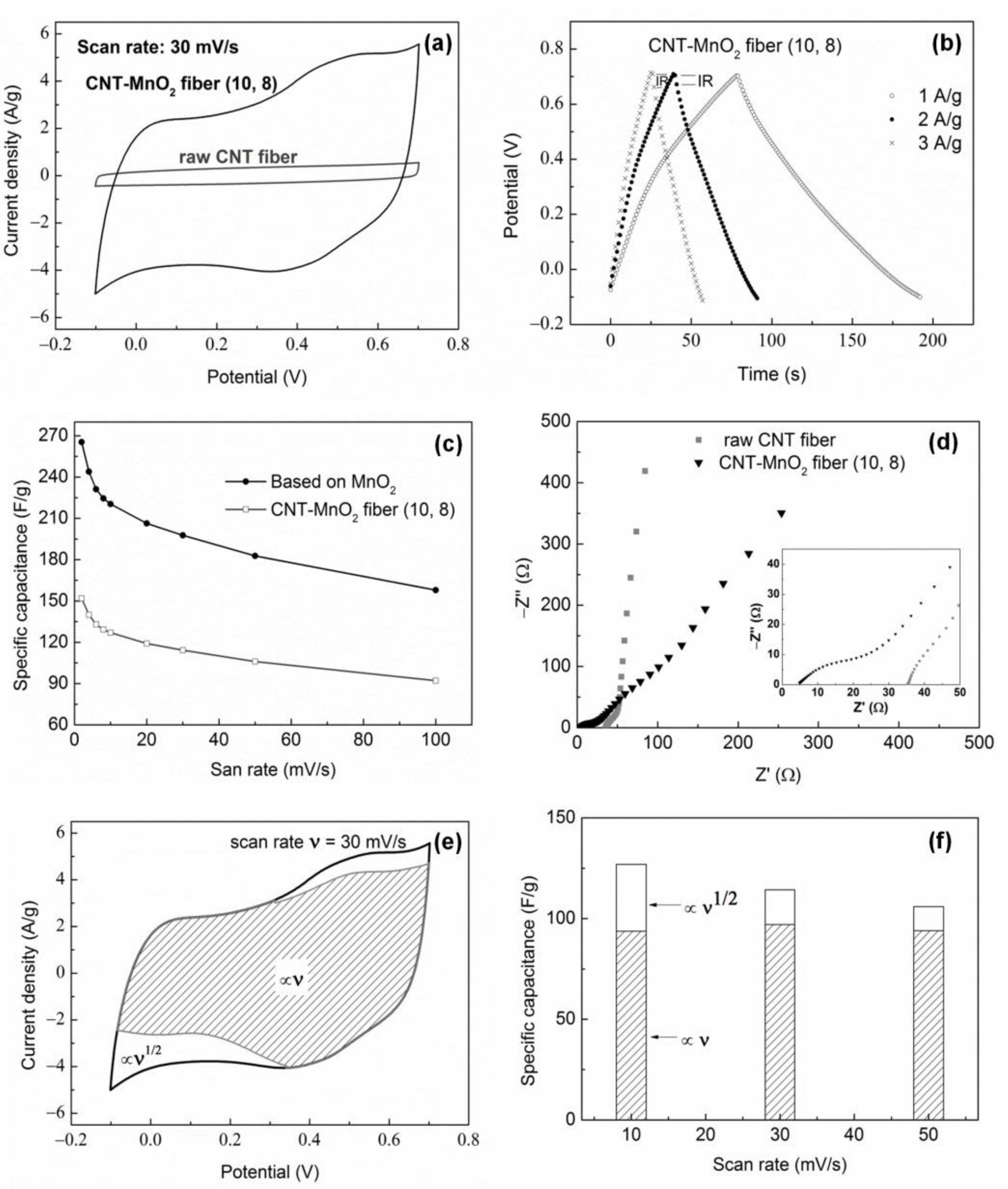
Figure 7). Details can be found in the experimental section. Electrochemical properties of the CNT–MnO
2 fiber (10, 8) electrode are shown in
Figure 8. The CV curve of the CNT–MnO
2 fiber electrode at a scan rate of 30 mV/s is compared with that of the raw CNT fiber electrode (
Figure 8a). The quasi-rectangular shape of the CV curves indicates good capacitive performance for both electrodes [
44]. Nevertheless, the current density increased significantly for the CNT–MnO
2 fiber electrode, owing to the pseudocapacitive contribution of MnO
2.
Figure 8b presents the CP curves of the CNT–MnO
2 fiber (10, 8) electrode at various current densities. The charge/discharge time duration increased with the decreasing current density from 3 A/g to 1 A/g. Furthermore, the potential drop (IR drop), which is caused by the internal resistance of the electrode [
45], became negligible by lowering the current density to 1 A/g.
The specific capacitance of the CNT–MnO
2 fiber (10, 8) electrode is plotted versus various scan rates in
Figure 8c. It shows that the capacitance decreased from 152 F/g to 92 F/g when the scan rate increased from 2 mV/s to 100 mV/s. Considering that the mechanism of the charge storage in MnO
2-based electrodes can be described as [
46]:
where
A represents an alkali metal cation, the capacity drop can be explained as follows: The charge storage process is mainly governed by the insertion/extraction of Na
+ and/or H
+-ions from the electrolyte into/from the MnO
2 nanoflakes. At faster scan rates, the Na
+/H
+ ions only reach the outer surface of the electrode [
47]. As a result, the available capacity decreases with the increasing scan rate. In contrast, the specific capacitance of the CNT fiber electrode was determined to be only ~10 F/g, which is consistent with the values reported in the literature [
16,
48]. Moreover, the capacitance of the CNT fiber was unaffected by the scan rate, owing to the rapid charging/discharging of the electrochemical double layers.
In order to estimate the specific capacitance based on MnO
2, the capacitance contribution of the CNTs needs to be subtracted from the total capacitance of the CNT–MnO
2 fiber (
Figure 8c). By taking into account that the total mass of the CNT–MnO
2 fiber electrode originates from both, the CNTs and the deposited MnO
2, the specific capacitance of MnO
2 alone at 2 mV/s can be estimated as 265 F/g. Furthermore, at a scan rate of 100 mV/s, the specific capacitance of MnO
2 is still as high as 158 F/g, indicating a high rate capacity of the electrode. So far, several studies [
21,
48,
49,
50,
51] have reported supercapacitive performance in CNT–MnO
2 electrodes [
22]. Li et al. [
49] reported that a CNT/MnO
2 film electrode with 20 wt.% MnO
2 delivered a specific capacitance of 151 F/g at a scan rate of 2 mV/s; Xie et al. [
51] reported a specific capacitance of 205 F/g at a scan rate of 2 mV/s with a CNT–MnO
2 pellet electrode, whereas only 43.2 F/g was measured at 50 mV/s. Compared with these previous studies, the CNT–MnO
2 fiber electrode in our study exhibits a similar specific capacitance, but it shows an improved rate capability as well as having the advantage of flexibility. The good capacitive behavior in our wire-shaped electrode can be explained as follows: (i) the direct deposition of MnO
2 nanoflakes on the CNT surfaces results in CNT–MnO
2 fibers where the highly conductive CNT scaffold provides high electronic conductivity; (ii) the small size of the MnO
2 nanoflakes promotes the pseudocapacitive reaction on the MnO
2 surface, which ensures that a large fraction of the nanoflakes perform as active sites and guarantees a high specific capacitance and a good rate capability; (iii) the hydrophilic channels inside the CNT fiber facilitate penetration of the electrolyte into the inner spaces of the fiber and enhance the ionic conductivity of the electrode material. This CNT–MnO
2 porous architecture enables the fiber electrode to have a fast electron and ion transport network, thus leading to excellent capacitive performance.
To estimate the specific capacitance of all the electrodes produced in this study, charge/discharge tests were performed between −0.1 V and 0.7 V. The results, summarized in
Table 5, show that the specific capacitance of the electrodes increased with increased loading of MnO
2, suggesting that it is mainly the pseudocapacitance of MnO
2 that contributes to the capacitance. In addition, the measured values of MnO
2-specific capacitance for the different CNT–MnO
2 fiber electrodes were highly comparable, which justifies the method used to acquire the specific capacitance of MnO
2. Based on these data, the CNT–MnO
2 fiber (10, 8) was chosen for further study due to its relatively high specific capacitance and mechanical integrity.
Figure 8d shows Nyquist plots obtained from the raw CNT fiber and the CNT–MnO
2 fiber (10, 8) electrodes analyzed by EIS. The Nyquist plots consist of (1) a high-frequency intercept on the real Z’ axis, (2) a semicircle arc in the high-to-medium-frequency, and (3) a low-frequency straight line [
52]. The high-frequency intercept corresponds to the series resistance (
Rs), which mainly concerns the contribution of the electrolyte resistance, the intrinsic resistance of the active electrode material, and the contact resistance at the interface of the active material/current collector [
53]. As can be seen in the insert of
Figure 8d, the
Rs values for the CNT fiber and for the CNT–MnO
2 fiber (10, 8) were ~35 Ω and 5 Ω, respectively. The large
Rs was probably caused by the contact resistance between the electrode and the current collector, as the fiber was too fine to have intimate contact with the current collector. The diameter of the semicircle corresponds to the charge transfer resistance (
Rct) at the electrode/electrolyte interface [
54]. The larger
Rct of the CNT–MnO
2 compared to the CNT fiber was due to the redox reaction of MnO
2. The slope of the low-frequency line is an indication of a diffusion process (if the slope is 45°) or a capacitive process (if the slope is 90°) [
55]. The nearly vertical line for the CNT fiber suggests good capacitive behavior, whereas the smaller slope for the CNT–MnO
2 fiber indicates the cation diffusion resistance in MnO
2, which follows from the charge storage mechanism (R1).
The specific capacitance of CNT–MnO
2 fibers, derived from the voltametric response at a scan rate of 30 mV/s (
Figure 8e), can be deconvoluted into a surface-limited process (∝ν, shaded area) and a diffusion-limited process, as described in the experimental section. From this data, we determined the total stored charge and the relative contributions associated with both diffusion-limited and surface-limited processes, as presented in
Figure 8f. The surface-limited process led to a specific capacitance of about 90 F/g and was independent of the scan rate. The contribution from the diffusion-limited process, in contrast, strongly depended on the scan rate, decreasing from 33 F/g to 12 F/g when the scan rate increased from 10 mV/s to 50 mV/s. This is due to the fact that, at higher scan rates, the ionic insertion is limited and contributes less to the capacitance.
The fractional contribution of the surface-limited process was about 65% for CNT–MnO2 fiber (10, 8) at a scan rate of 4 mV/s, whereas it was 94% for CNT–MnO2 fiber (10, 4). This large difference may be attributed to thinner MnO2 flakes present in the CNT–MnO2 fiber (10, 4) and/or less dense loading of MnO2 flakes, leading to a larger specific surface area due to the larger area of exposed CNT surfaces.
In order to access the structural changes of the CNT–MnO
2 fibers after electrochemical measurements, Raman spectroscopy was carried out (see
Supplementary Materials, Figure S2). The I
G/I
D remained constant at 1.05 after testing, indicating the structural integrity of the CNT–MnO
2 fiber, which is an important aspect for the cyclic stability of the electrode [
56]. On the other hand, a band at ~650 cm
−1 was present after testing. This peak is assigned to the Mn–O breathing vibration of Mn
2+ in tetrahedral coordination, which indicates the existence of a Mn
3O
4 phase [
36]. The formation of Mn
3O
4 could have been promoted by the immersion of the electrode in Na
2SO
4 solution [
57].
Finally, a symmetric supercapacitor was assembled using two CNT–MnO
2 (10, 8) fibers as electrodes and PVA/H
3PO
4 polymer as the solid electrolyte. The digital photos of the fabricated transparent and flexible supercapacitor are shown in
Figure 9a. The supercapacitor had a length of ~5.5 cm and showed no breakage during bending. The ionic conductivity of the PVA/H
3PO
4 polymer electrolyte relies on the segmental motion of the PVA chain in the amorphous polymer phase [
58]. X-ray diffraction (XRD) was used to examine the crystal structure of the synthesized polymer electrolyte (
Supplementary Materials, Figure S3). The pure PVA showed two peaks at the 2-theta angles of ~121° and 40°, corresponding to the semi-crystalline structure of PVA [
59]. In contrast, the PVA/H
3PO
4 displayed much weaker and broader peaks, revealing the amorphous nature of the PVA/H
3PO
4 polymer electrolyte. Hence, the PVA/H
3PO
4 mass ratio of 1:2 used in this study can be considered as referring to a polymer electrolyte with higher ionic conductivity compared to pure PVA.
CV curves at different scan rates and CP curves at various current densities of the symmetric supercapacitor at a potential window of 0 to 1 V are displayed in
Figure 9b,c. The nearly rectangular shape of the CV curves and the symmetric triangular shape of the CP curves were well maintained through the measurements, indicating the good capacitive behavior of the electrodes. However, a notable IR drop (0.1 V) was observed at the current density of 1 A/g, which can be ascribed to a non-negligible internal resistance of the device. The specific capacitance for the supercapacitor was 17.1 F/g at a current density of 1 A/g. This value was smaller compared to the capacitance determined by the three-electrode measurement (145 F/g), which was most probably caused by the high resistance of the polymer electrolyte. The supercapacitor showed a good cycling stability of almost 100% retention after 1200 cycles at 1 A/g (
Figure 9d).
In general, the length-specific capacitance is utilized to evaluate the charge–discharge capacity of fiber-shaped supercapacitors [
60]. As can be seen in
Table 6, the length-specific capacitance decreased from 750 µF/cm to 622 µF/cm as the current density increased from 0.2 A/g to 1 A/g. This behavior was due to the insufficient time for the ions to approach the electrodes during fast charge/discharge processes. Notably, the length-specific capacitances of the supercapacitor are comparable with or even exceed those of many previously reported wire-shaped supercapacitors [
1,
2,
21,
24,
61,
62].
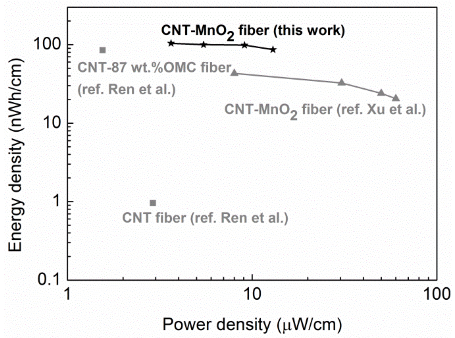
Energy and power density are two important parameters that help in evaluating the electrochemical performance of supercapacitors. Based on the CP curves, the energy density and power density were calculated, and they are displayed in a Ragone plot in
Figure 10. The supercapacitor demonstrated a length energy density of 86 nWh/cm, while the length power density was 13 µW/cm at a current density of 1 A/g. The length energy density of our device surpassed the supercapacitors reported by Xu et al. [
24] and Ren el al. [
1], which are based on CNT–MnO
2 fibers and CNT-OMC fiber, respectively. This high energy density can be attributed to the high and efficient loading of MnO
2 achieved by immersing CNT fibers in KMnO
4. However, the length specific power density was lower than the value reported in [
24], which could be due to the high series and diffusive resistance in the device.
To investigate the influence of the electrolyte, two-electrode measurement was also performed with 1 M Na
2SO
4 bulk solution as the electrolyte. The supercapacitor delivered a specific capacitance of 44 F/g at 1 A/g, which corresponds to 176 F/g for a single electrode. This value is comparable with the results obtained from the three-electrode measurement (
Table 5). Mechanical performance of the tested wire-shaped capacitor was examined (
Supplementary Materials, Figure S3) and a tensile strength of 274 MPa and strain-to-failure of 4.2% were found, which are comparable to cotton or silk fibers [
28]. These results demonstrate that CNT–MnO
2 fibers are promising candidates for electrodes in flexible supercapacitors and suggest that future work on device optimization is needed to improve their performance, in particular by addressing the problem of high resistance mentioned above.
In conclusion, MnO2 nanoflakes were homogeneously deposited onto CNT fibers through the direct redox reaction between CNTs and KMnO4. By tuning the concentration of the KMnO4 solution and the reaction time, different loadings of MnO2 were achieved. This very simple approach led to a homogeneous loading of CNT fibers with MnO2 nanoflakes of 2–3 nm in diameter. After decoration, CNT fibers changed from hydrophobic to hydrophilic while maintaining their flexibility and structural integrity. This simple one-step conversion was essential for the efficient loading of MnO2 nanoflakes, as well as to achieve sufficient adhesion between the electrodes and the electrolyte in the supercapacitor. The surface energy components of the MnO2-decorated CNT fibers were estimated by contact angle measurements. The CNT–MnO2 fiber electrode presented high capacitance, good rate performance, and a long cycle life in Na2SO4 solution. The contribution of the surface-limited process was as high as 65% for CNT–MnO2 fiber (10, 8).
In addition, a symmetric wire-shaped supercapacitor composed of CNT–MnO2 fiber electrodes and PVA/H3PO4 gel electrolyte was fabricated. The wire-shaped supercapacitor demonstrated a high length-specific capacitance of 621.8 µF/cm, with absolute cycle stability over 1200 cycles. The simple and tunable fabrication method for MnO2–CNT composite fibers reported in this work shows promising performance for use in the production of flexible and wearable fiber electrodes for future energy devices. Our detailed study also highlights the importance of the surface and mechanical properties of the fibers for the preparation and the performance of the wire-shaped supercapacitor, which have rarely been covered in the literature.
3. Experimental Section
Non-densified CNT fibers were used as a scaffold to form the composite electrode in this study. Individual CNTs have an average diameter of 15 nm with about 10 walls in average. Details about CNTs and the dry-spun CNT fibers can be found in our previous work [
29]. The estimated densities of CNTs [
16] and of the non-densified CNT fibers are 1.61 and 0.13 g/cm
3, respectively. Thus, the calculated porosity of the non-densified CNT fiber is about 92%.
For the preparation of CNT–MnO
2 fiber electrodes, MnO
2 was spontaneously deposited onto the CNT fibers through a direct redox reaction between the CNTs and KMnO
4, according to the following chemical reaction [
25,
63]:
The procedure was as follows: (1) the raw CNT fiber was immersed in aqueous solutions (aq) with different concentrations of KMnO4 at 80 °C. (2) It was taken out after different reaction times and rinsed with deionized water to remove any excess solution. (3) The sample was annealed at 200 °C for 2 h to form CNT–MnO2 fiber. The weights of the raw CNT fiber and the CNT–MnO2 fiber were measured with a microbalance (Gamry Instruments, Warminster, PA, USA)with a weighing precision of ±10 μg. The effective mass loading of MnO2 was extracted from the weight difference based on (R2). The produced fibers are denoted “CNT–MnO2 fiber (c, t)”, where c stands for the KMnO4 solution concentration used (1 mM or 10 mM), and t represents the reaction time (4 h, 8 h, or 12 h).
For the fabrication of solid state supercapacitors, 1 g polyvinyl alcohol (PVA, Mw = 125,000 g/mol) was added to a mixed solution of 10 g deionized water and 2 g H
3PO
4 (85 wt.%). The mixture was constantly stirred at 85 °C until a transparent gel was formed. Two CNT–MnO
2 fibers were coated with the gel electrolyte and dried at room temperature in a fume hood for 30 min. Subsequently, both fibers were carefully placed next to each other. The electrical resistance between these fibers was monitored with a multimeter to avoid any electrical short circuit. Finally, a thin layer of PVA/H
3PO
4 gel was applied again on the outside of the fibers to complete the fabrication of the wire-shaped solid state supercapacitor. The fabrication procedure of the wire-shaped supercapacitor is schematically illustrated in
Figure 1.
CNT fibers were characterized with a scanning electron microscope (SEM, FEI Nova NanoSEM 450, Eindhoven, The Netherlands) equipped with an energy-dispersive X-ray spectrometer (Octane, EDAX, Mahwah, NJ, USA) (EDS). A probe-corrected transmission electron microscope (ARM200F cold-FEG, JEOL, Tokyo, Japan) was used to visualize the CNT and MnO
2 structures (operated at an acceleration voltage of 200 kV) in the CNT–MnO
2 composite. XPS studies were performed on a Thermo Fisher ESCALAB 250 Xi spectrometer (Waltham, MA, USA) equipped with an Al Kα monochromated X-ray source (1486.6 eV, spot diameter 500 μm). The charge neutralization of the sample was realized with a flood gun (Thermo Fisher, Waltham, MA, USA) using low-energy Ar
+ ions and electrons. Samples were analyzed with a pass energy of 150 eV for survey spectra and 20 eV for high resolution scans. All binding energies were referenced to the adventitious C 1 s peak at 284.8 eV to correct the shift caused by charge effect. High resolution spectra were decomposed with a Gaussian/Lorentzian product function using XPS Peak 4.1 (freeware) (Shatin, Hong Kong, 2000). Raman spectroscopy was performed using an Ar-ion laser with the wavelength of 532 nm (Senterra, Bruker Optics, Billerica, MA, USA). The wettability of CNT–MnO
2 fiber was studied with the tensiometric method [
29] (Krüss K100SF) and surface energy components were derived by using the acid–base model [
41,
64]. The crystal structure of the PVA/H
3PO
4 solid polymer electrolyte was characterized by a Philips X’Pert X-ray diffractometer (XRD) (Eindhoven, The Netherlands) operating at 40 mA and 40 kV using monochromated Cu Kα1 radiation (wavelength = 1.54056 Å, step size = 0.2°).
Single-fiber tensile tests were performed according to the ASTM D3379 standard with a dynamic mechanical analyzer (Q800, TA Instruments, New Castle, DE, USA). A single CNT or CNT–MnO
2 fiber was attached to a paper tab using adhesive. The paper tab was fixed with a tensile clamp and cut into two parts before testing (see
Supplementary Materials, Figure S1). A preload of 3 mN was applied at the beginning to stretch the fibers. The extension rate was set to 500 µm/min. An 18 N load cell with a resolution of 1 µN and a crosshead with a displacement resolution of 1 nm were used to record force and displacement. The gauge length was measured automatically before each test. At least five samples were tested for each type of fiber.
In order to determine the tensile strength of CNT fibers, accurate measurement of the fiber cross-section areas is required. Cross-sectional area was calculated from the fiber diameter (assuming the fiber was a cylinder). Diameters measured at five different locations of the fiber by means of SEM were averaged. The force and displacement signals were then converted into stress and strain. The tensile strength of the fiber was taken as the maximum stress, and the stiffness was derived from the tangent slope of the stress–strain curve between 0.1% and 0.3% strain [
33].
The electrochemical behaviors of the CNT fibers and CNT–MnO
2 fibers were evaluated by cyclic voltammetry (CV), chronopotentiometry (CP), and electrochemical impedance spectroscopy (EIS) techniques on an Autolab electrochemical workstation at room temperature. A three-electrode cell configuration was employed, consisting of the raw CNT or CNT–MnO
2 fiber as the working electrode, a Pt gauze as the counter electrode, a saturated calomel electrode (SCE) as the reference electrode, and 1 M Na
2SO
4 solution as the electrolyte (
Figure 7). The fiber was clamped between current collectors (two pieces of graphite). CV measurements were carried out between −0.1 V and 0.7 V (vs. SCE) at various scan rates ranging from 2 mV/s to 100 mV/s (in this voltage window the CV curves were rectangular, while an unsuitable voltage window led to a deformed CV curve, see, e.g.,
Figure S5). The CP was also conducted in the same voltage window at different specific currents ranging from 1 A/g to 3 A/g. EIS measurements were carried out in a frequency range from 10 kHz to 0.01 Hz at open circuit potential with an amplitude of 5 mV.
The electrochemical performances of the supercapacitor were tested in a two-electrode configuration in the voltage range of 0 V and 1 V. In the three-electrode system, the average specific capacitance of the electrodes was calculated from the CV diagrams according to Equation (1) [
63]:
where
Cs,electrode(F/g) is the mass specific capacitance,
m(g) is the mass of the active material on the electrode, and ∆
V(V) is the voltage window.
qa and
qc are the anodic and cathodic charges in coulombs, respectively. The
Cs,electrode was calculated from the CP curves by using Equation (2):
where
I(A) is the discharge current and ∆
t(s) is the discharge time. In the two-electrode system, the
Cs,electrode was derived from Equation (3)
where
M(g) is the total mass of the active materials on the positive and negative electrodes, with
M = 2
m in a symmetric supercapacitor. The energy and power densities of supercapacitors were calculated from:
where
Edevice(Wh/kg) is the energy density,
Cdevice(F/g) is the capacitance of the supercapacitor,
V(V) is the cell voltage, and
Pdevice(W/kg) is the power density. The mass of the active material
m in the above equations can be replaced with the length of the electrode to acquire the average length-specific capacitances
Clength.
Taking (R1) into account, the total stored charge can be separated into three components: (i) the Faradaic contribution from the alkali metal cations (
A+) insertion process, (ii) the Faradaic contribution from the charge-transfer process with surface atoms, i.e., pseudocapacitance, and (iii) the non-Faradaic contribution from the double layer charging. The first component is a diffusion-limited process while the latter two components are surface-limited processes. These capacitive effects can be characterized by analyzing the CV data at various scan rates according to [
65]:
where
i is the measured current,
a is a material-dependent constant,
υ is the scan rate, and
b is a parameter that relates to the charge storage mechanism. For voltametric processes controlled by diffusion,
b = 0.5; for non-insertion capacitive processes,
b = 1. Consequently, the measured current
i at a fixed potential
(V) can be expressed as [
66]:
where
k1 and
k2 are scan rate-independent constants.
k1υ and
k2υ1/2 correspond to the current contributions from the surface-limited process and the diffusion-limited process, respectively. Equation (7) can be transformed into:
By plotting the scan rate dependence of the current according to Equation (8), the values of k1 and k2 were obtained from the slope and the y-axis intercept, respectively.


 ,
, 


