
Solvothermal Synthesis of a Novel Calcium Metal-Organic Framework: High Temperature and Electrochemical Behaviour


 , , , , and
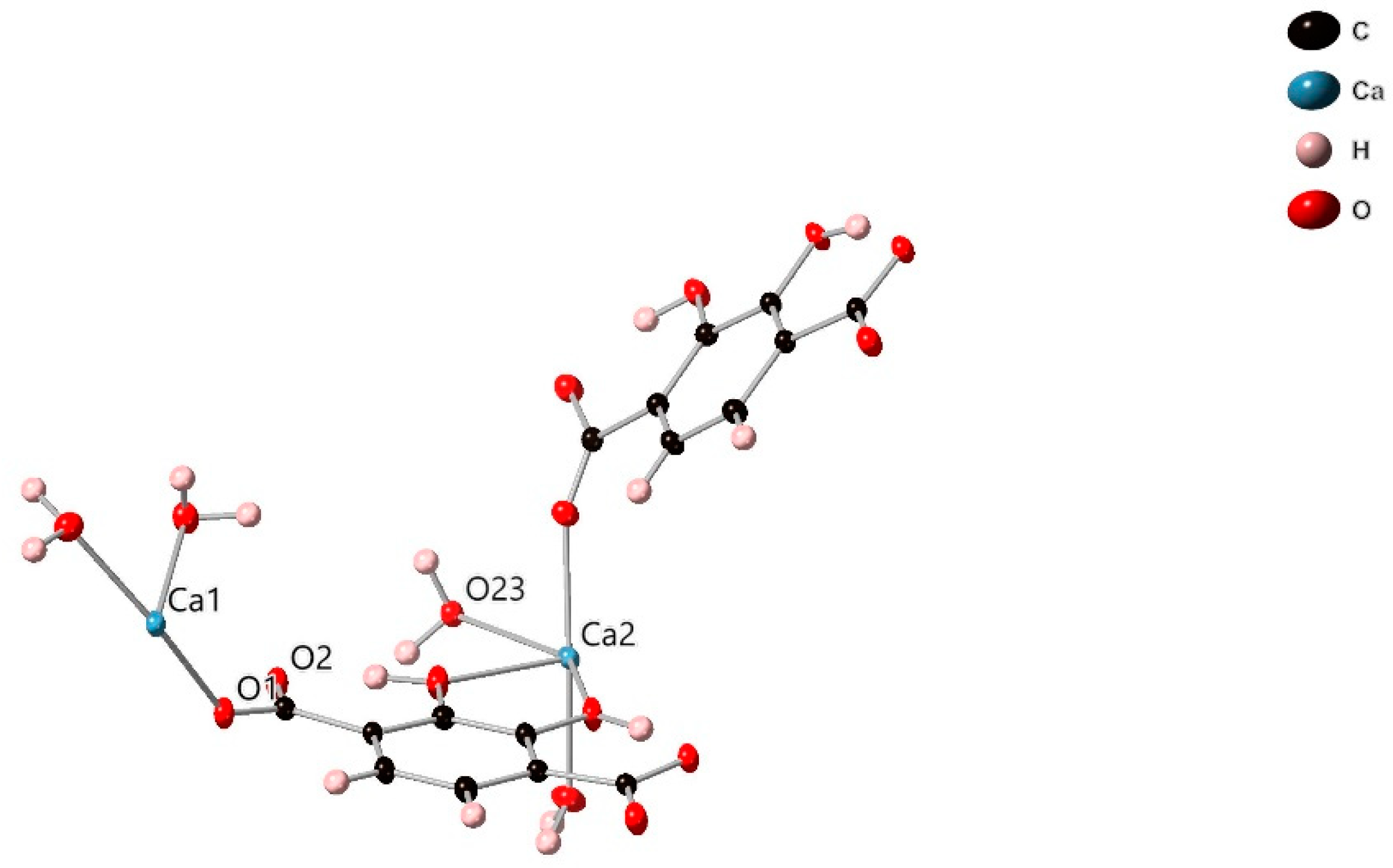
Abstract
:1. Introduction
2. Results and Discussion
2.1. Synthesis Route
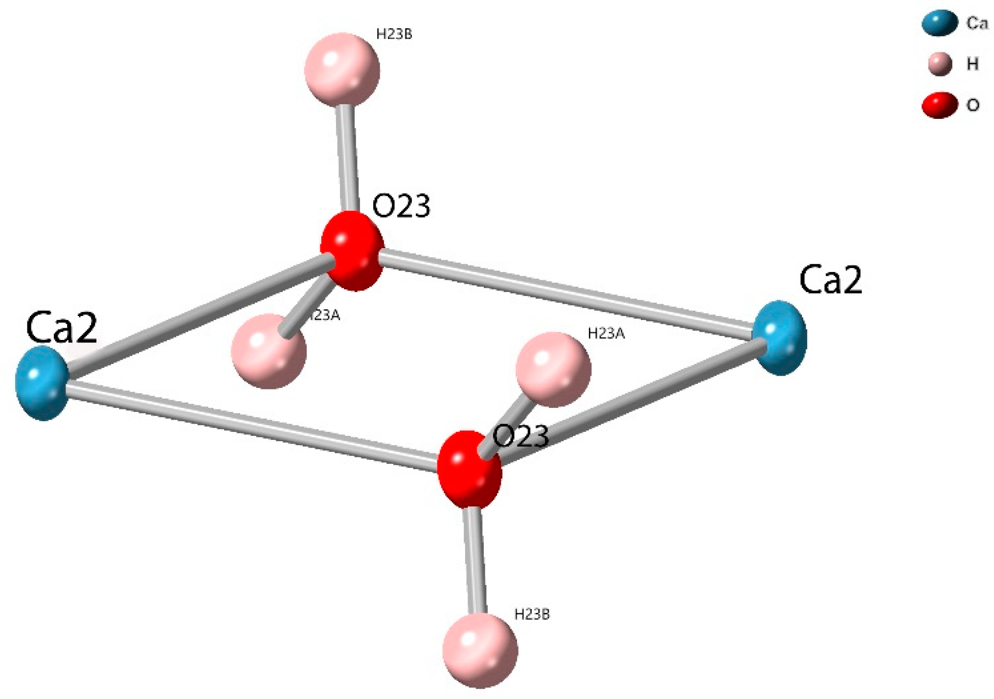
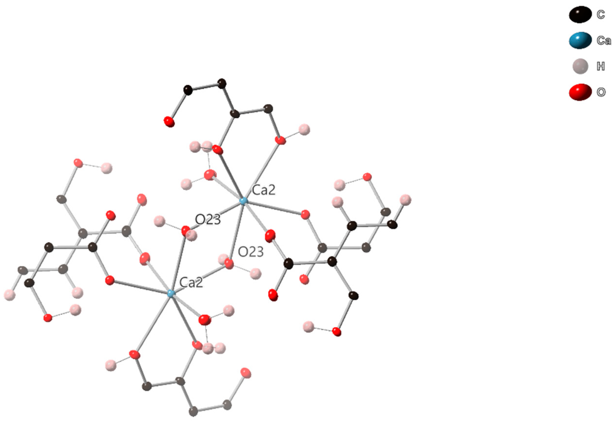
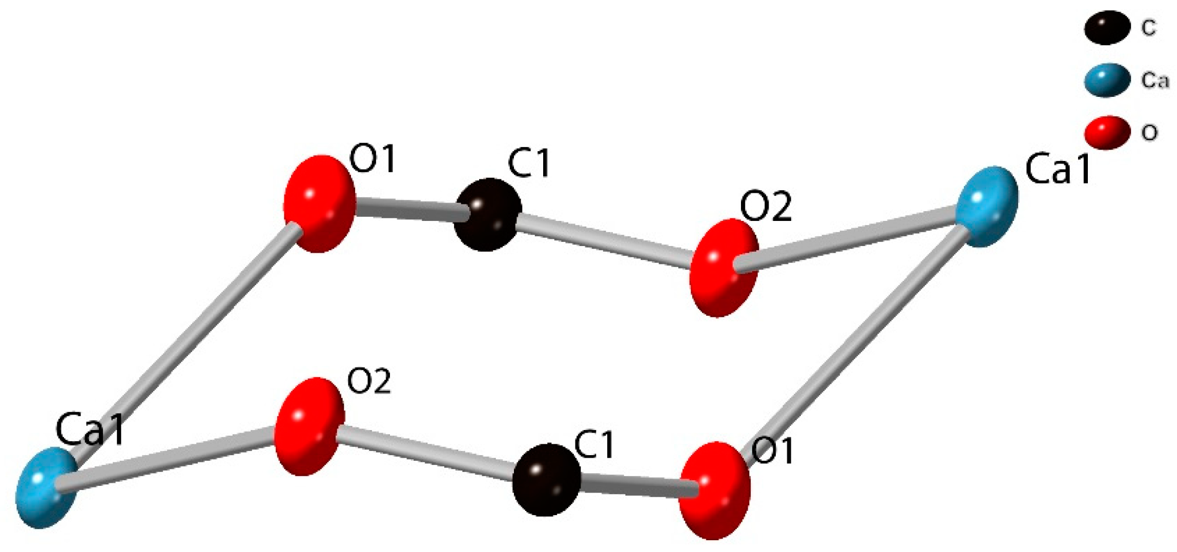
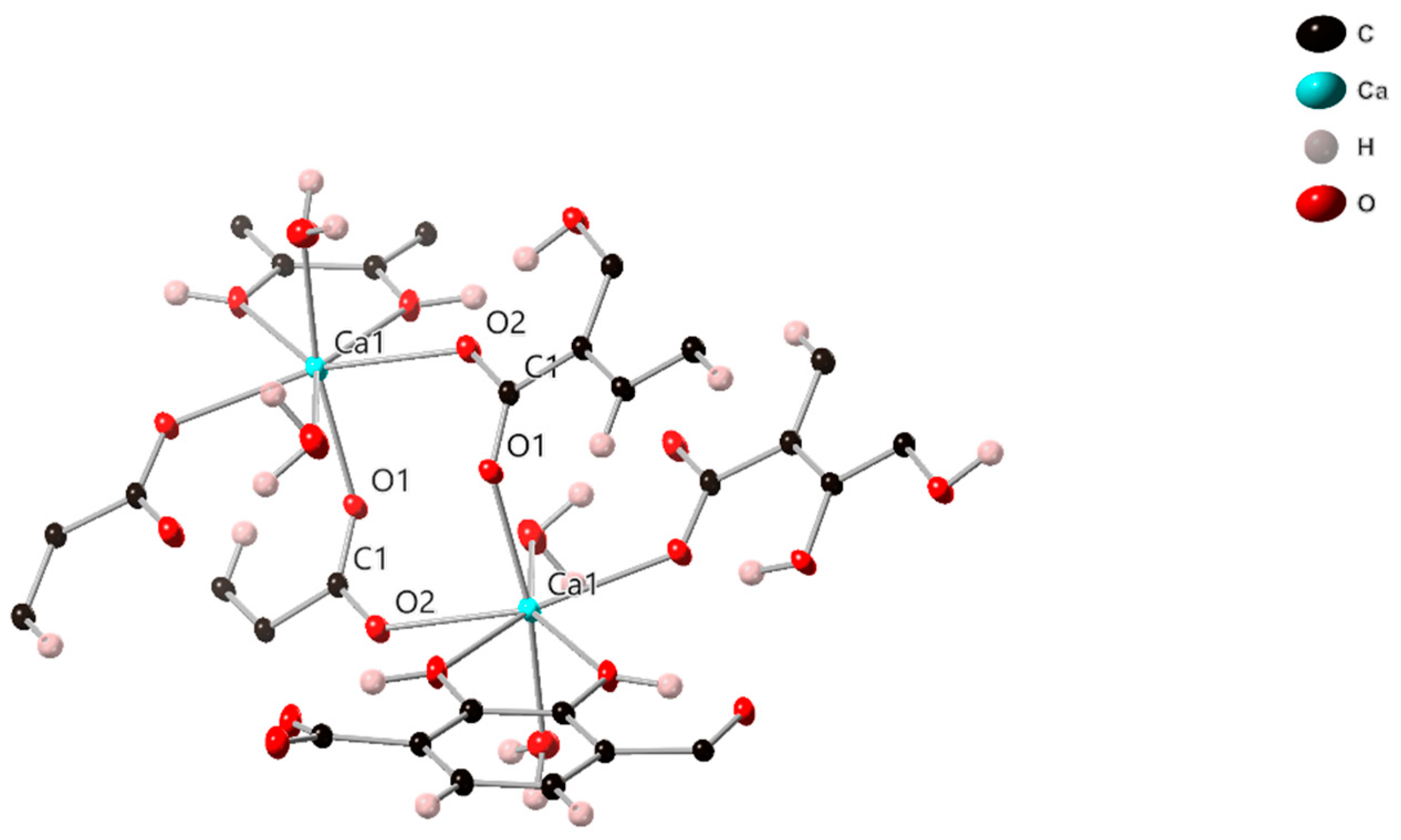
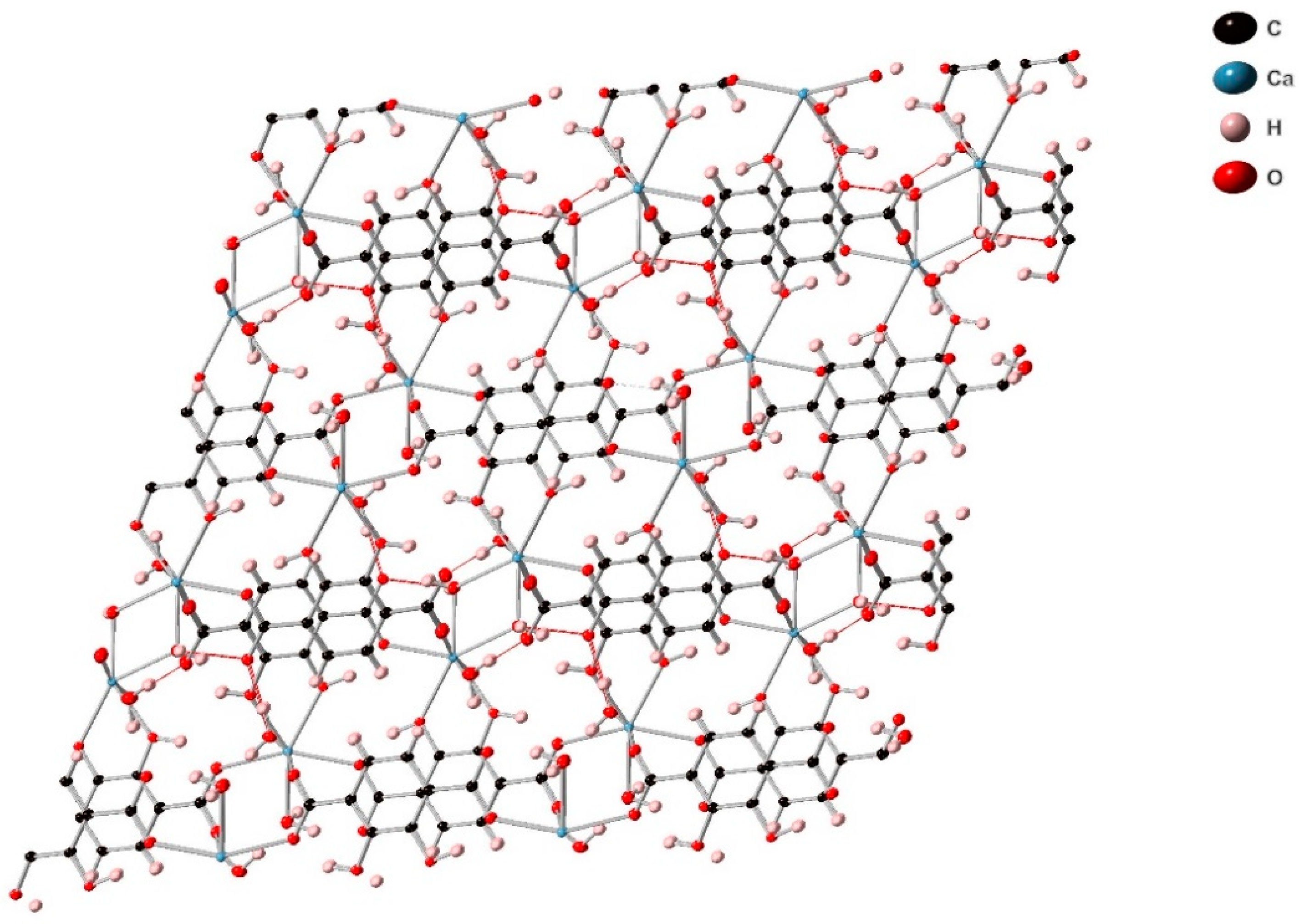
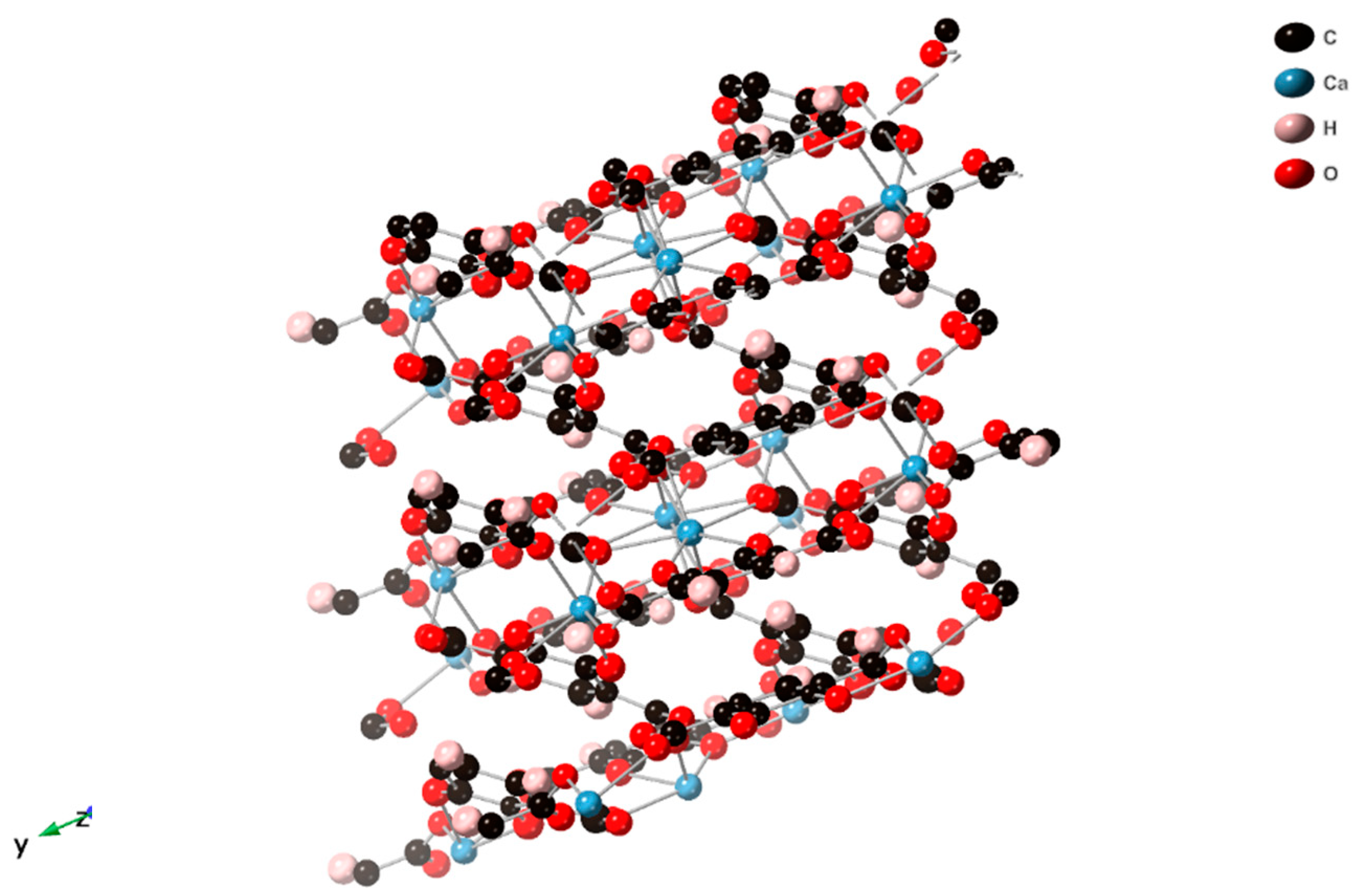
2.2. Description of Crystal Structure
2.3. Characterisation
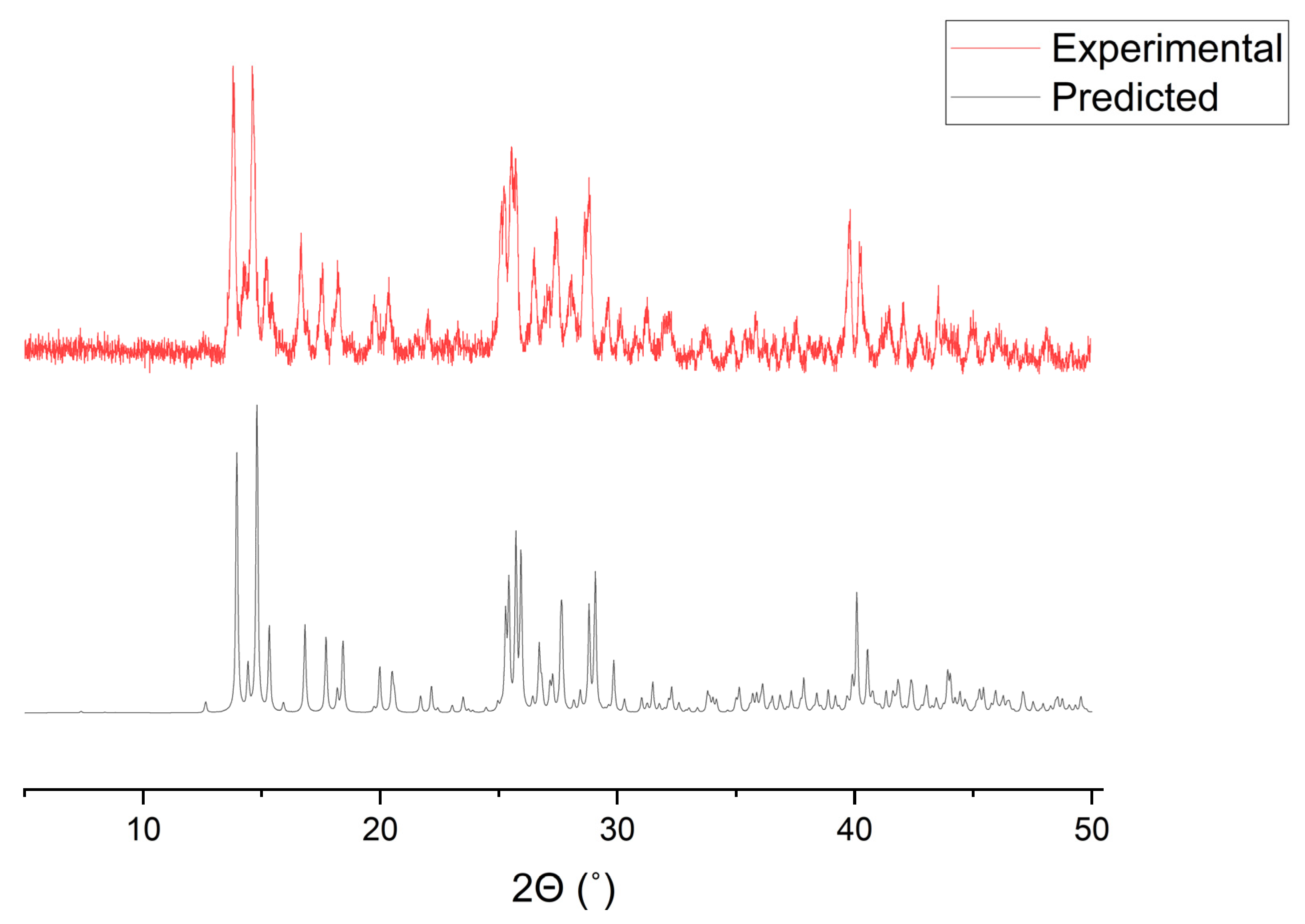
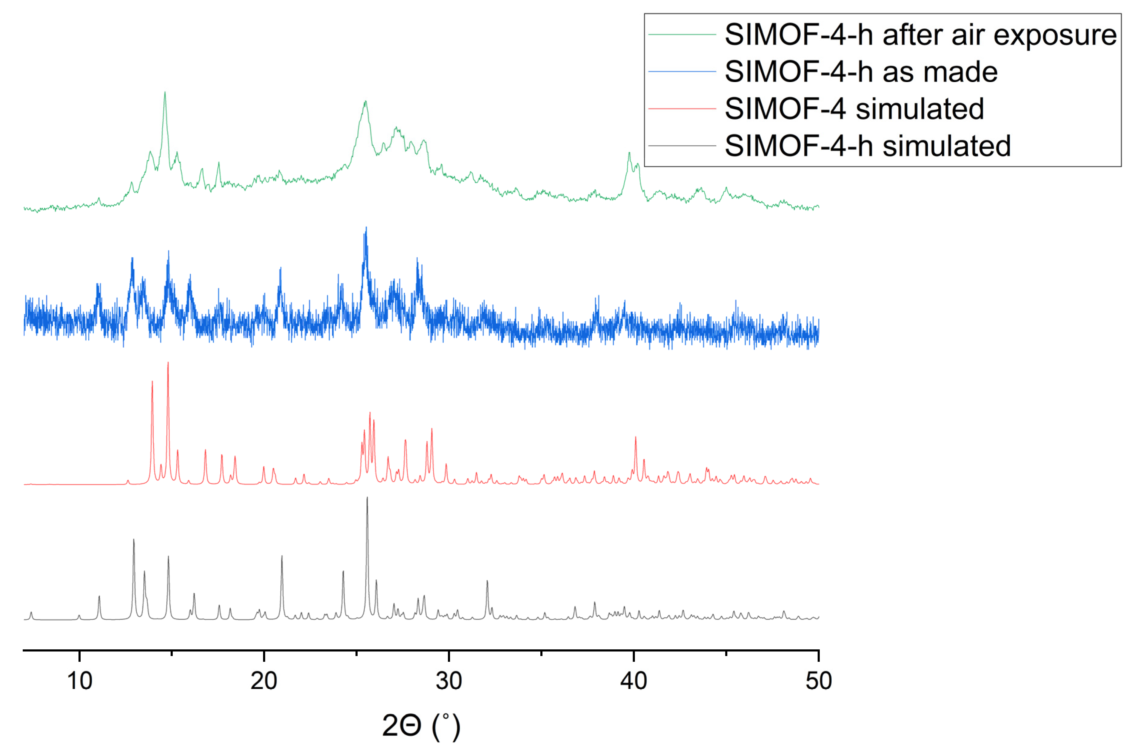
2.3.1. Powder X-ray Diffraction
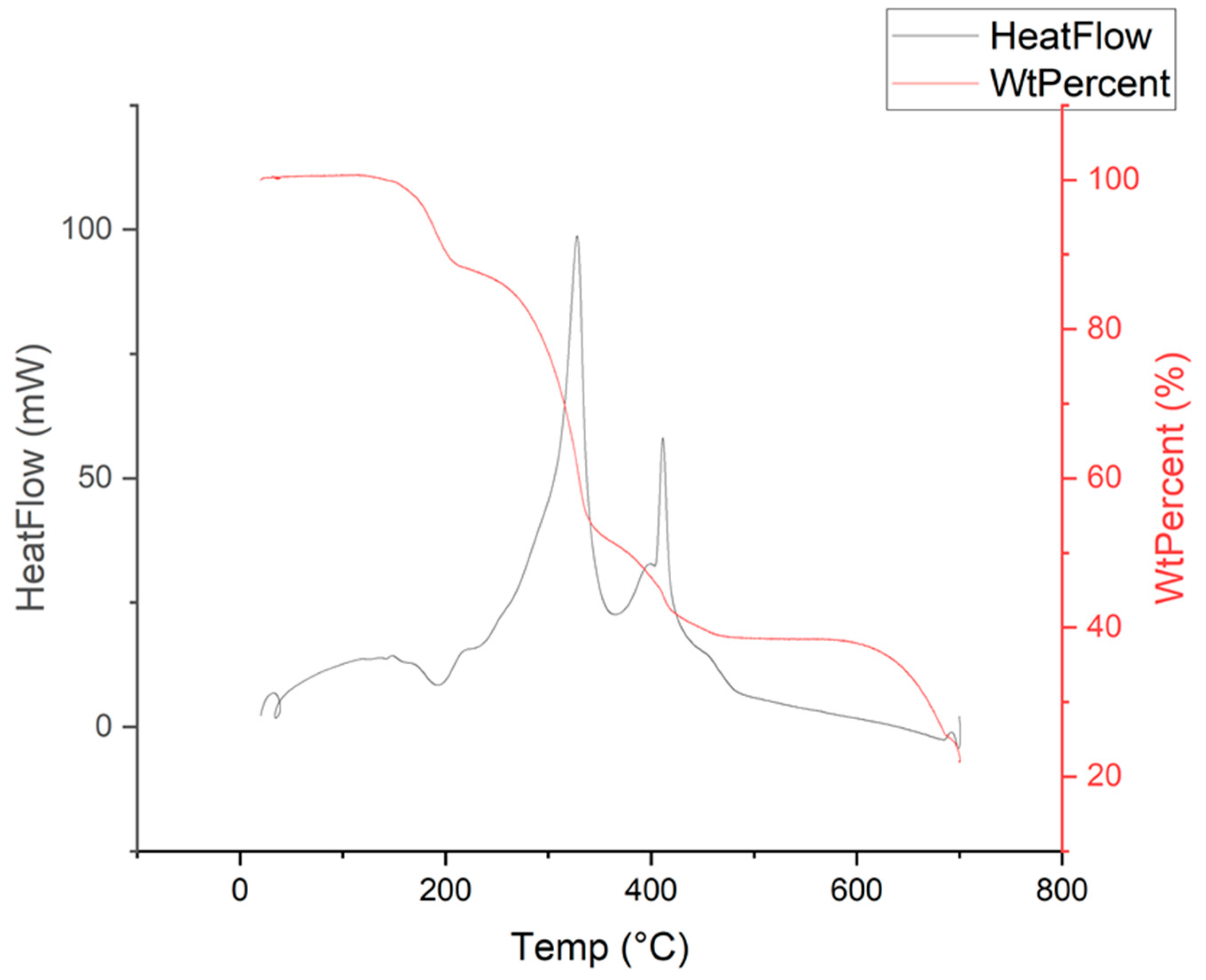
2.3.2. Thermo-Gravimetric Analysis
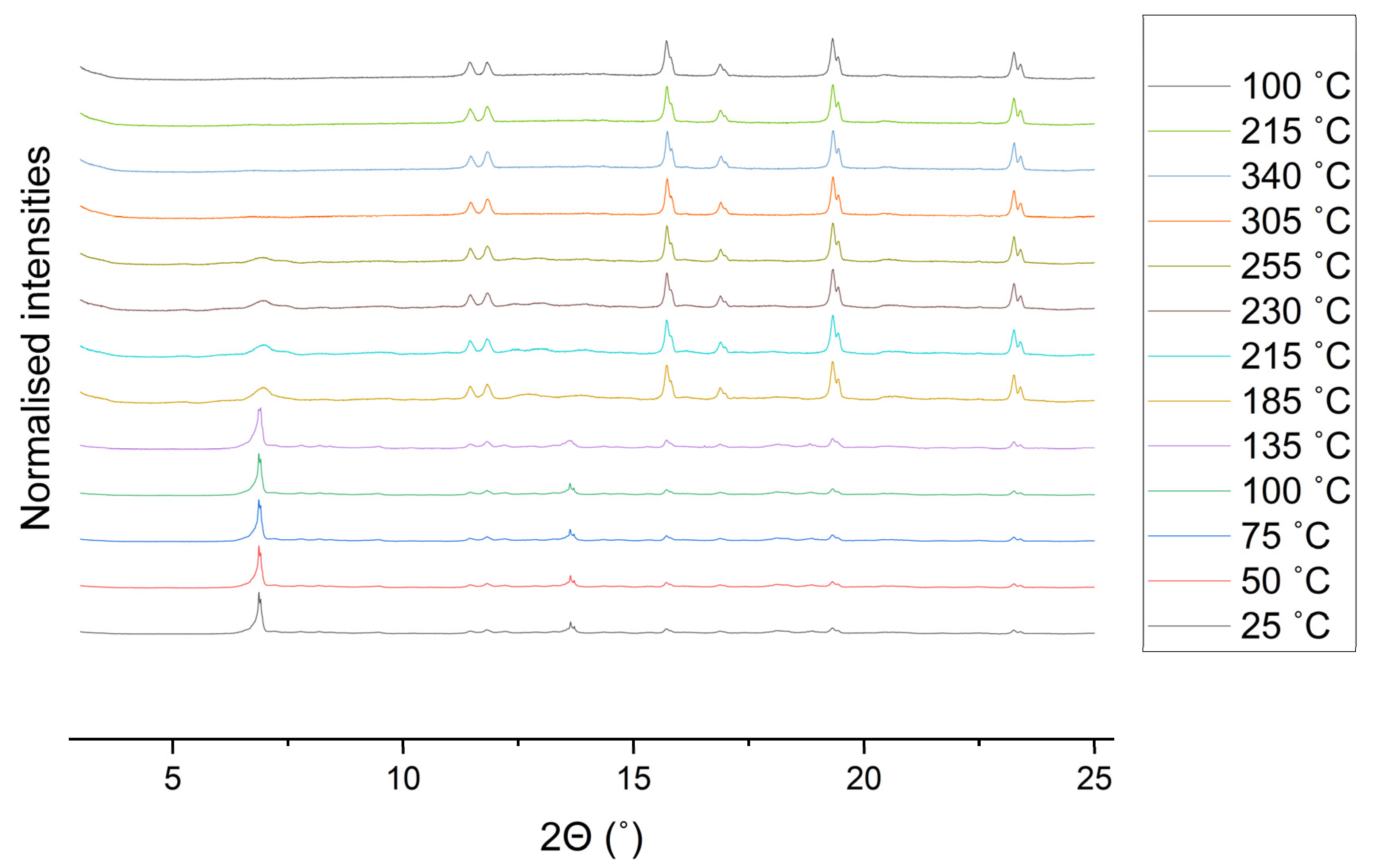
2.3.3. Variable Temperature Behaviour
2.3.4. Single Crystal Structure of High Temperature Form
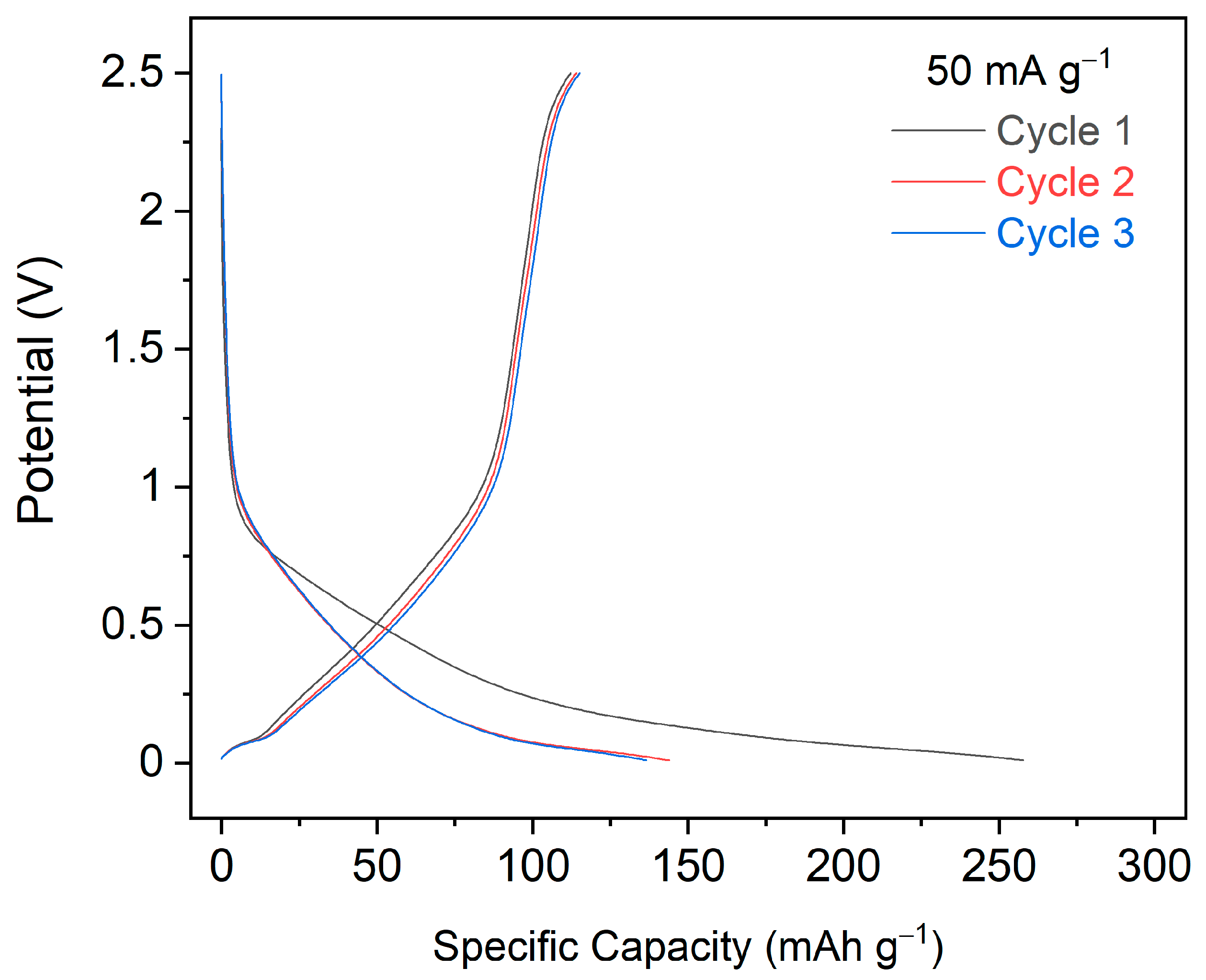
2.3.5. Electrochemistry
3. Materials and Methods
3.1. General Remarks
3.2. Preparation of 2,3-Dhtp
3.3. Preparation of SIMOF-4
3.4. Preperation of SIMOF-4-h
3.5. X-ray Crystallography
3.6. Electrochemical Testing
4. Conclusions
Supplementary Materials
Author Contributions
Funding
Institutional Review Board Statement
Informed Consent Statement
Data Availability Statement
Acknowledgments
Conflicts of Interest
Sample Availability
References
- Howarth, A.J.; Peters, A.W.; Vermeulen, N.A.; Wang, T.C.; Hupp, J.T.; Farha, O.K. Best practices for the synthesis, activation, and characterization of metal−organic frameworks. Chem. Mater. 2017, 29, 26–39. [Google Scholar] [CrossRef]
- Stock, N.; Biswas, S. Synthesis of Metal-Organic Frameworks (MOFs): Routes to Various MOF Topologies, Morphologies, and Composites. Chem. Rev. 2012, 112, 933–969. [Google Scholar] [CrossRef]
- Batten, S.R.; Champness, N.R.; Chen, X.M.; Garcia-Martinez, J.; Kitagawa, S.; Öhrström, L.; O’Keeffe, M.; Suh, M.P.; Reedijk, J. Terminology of metal-organic frameworks and coordination polymers (IUPAC recommendations 2013). Pure Appl. Chem. 2013, 85, 1715–1724. [Google Scholar] [CrossRef] [Green Version]
- Guo, X.; Geng, S.; Zhuo, M.; Chen, Y.; Zaworotko, M.J.; Cheng, P.; Zhang, Z. The utility of the template effect in metal-organic frameworks. Coord. Chem. Rev. 2019, 391, 44–68. [Google Scholar] [CrossRef]
- Schneemann, A.; Bon, V.; Schwedler, I.; Senkovska, I.; Kaskel, S.; Fischer, R.A. Flexible metal-organic frameworks. Chem. Soc. Rev. 2014, 43, 6062–6096. [Google Scholar] [CrossRef] [PubMed] [Green Version]
- Yuan, S.; Feng, L.; Wang, K.; Pang, J.; Bosch, M.; Lollar, C.; Sun, Y.; Qin, J.; Yang, X.; Zhang, P.; et al. Stable Metal–Organic Frameworks: Design, Synthesis, and Applications. Adv. Mater. 2018, 30, 1704303. [Google Scholar] [CrossRef] [PubMed] [Green Version]
- Song, P.; Li, Y.; He, B.; Yang, J.; Zheng, J.; Li, X. Hydrogen storage properties of two pillared-layer Ni(II) metal-organic frameworks. Microporous Mesoporous Mater. 2011, 142, 208–213. [Google Scholar] [CrossRef]
- Tian, T.; Zeng, Z.; Vulpe, D.; Casco, M.E.; Divitini, G.; Midgley, P.A.; Silvestre-Albero, J.; Tan, J.C.; Moghadam, P.Z.; Fairen-Jimenez, D. A sol-gel monolithic metal-organic framework with enhanced methane uptake. Nat. Mater. 2018, 17, 174–179. [Google Scholar] [CrossRef]
- Ding, M.; Flaig, R.W.; Jiang, H.L.; Yaghi, O.M. Carbon capture and conversion using metal-organic frameworks and MOF-based materials. Chem. Soc. Rev. 2019, 48, 2783–2828. [Google Scholar] [CrossRef]
- Denny, M.S.; Moreton, J.C.; Benz, L.; Cohen, S.M. Metal-organic frameworks for membrane-based separations. Nat. Rev. Mater. 2016, 1, 16078. [Google Scholar] [CrossRef]
- Dong, Q.; Zhang, X.; Liu, S.; Lin, R.; Guo, Y.; Ma, Y.; Yonezu, A.; Krishna, R.; Liu, G.; Duan, J.; et al. Tuning Gate-Opening of a Flexible Metal–Organic Framework for Ternary Gas Sieving Separation. Angew. Chem. 2020, 59, 22756–22762. [Google Scholar] [CrossRef]
- DeCoste, J.B.; Peterson, G.W. Metal-organic frameworks for air purification of toxic chemicals. Chem. Rev. 2014, 114, 5695–5727. [Google Scholar] [CrossRef] [PubMed]
- Kadhom, M.; Deng, B. Metal-organic frameworks (MOFs) in water filtration membranes for desalination and other applications. Appl. Mater. Today 2018, 11, 219–230. [Google Scholar] [CrossRef]
- Llabrés i Xamena, F.X.; Abad, A.; Corma, A.; Garcia, H. MOFs as catalysts: Activity, reusability and shape-selectivity of a Pd-containing MOF. J. Catal. 2007, 250, 294–298. [Google Scholar] [CrossRef]
- Kumar, P.; Deep, A.; Kim, K.H. Metal organic frameworks for sensing applications. TrAC Trends Anal. Chem. 2015, 73, 39–53. [Google Scholar] [CrossRef]
- Dong, C.; Xu, L. Cobalt- and Cadmium-Based Metal–Organic Frameworks as High-Performance Anodes for Sodium Ion Batteries and Lithium Ion Batteries. ACS Appl. Mater. Interfaces 2017, 9, 7160–7168. [Google Scholar] [CrossRef] [PubMed]
- McKinlay, A.C.; Morris, R.E.; Horcajada, P.; Férey, G.; Gref, R.; Couvreur, P.; Serre, C. BioMOFs: Metal-organic frameworks for biological and medical applications. Angew. Chem. Int. Ed. 2010, 49, 6260–6266. [Google Scholar] [CrossRef]
- Desai, D.A.V.; Morris, P.R.E.; Armstrong, D.A.R. Advances in Organic Anode Materials for Na-/K-Ion Rechargeable Batteries. ChemSusChem 2020, 13, 4866. [Google Scholar] [CrossRef]
- Abánades Lázaro, I.; Forgan, R.S. Application of zirconium MOFs in drug delivery and biomedicine. Coord. Chem. Rev. 2019, 380, 230–259. [Google Scholar] [CrossRef] [Green Version]
- Hinks, N.J.; McKinlay, A.C.; Xiao, B.; Wheatley, P.S.; Morris, R.E. Metal organic frameworks as NO delivery materials for biological applications. Microporous Mesoporous Mater. 2010, 129, 330–334. [Google Scholar] [CrossRef]
- Henkelis, S.E.; Vornholt, S.M.; Cordes, D.B.; Slawin, A.M.Z.; Wheatley, P.S.; Morris, R.E. A single crystal study of CPO-27 and UTSA-74 for nitric oxide storage and release. CrystEngComm 2019, 21, 1857–1861. [Google Scholar] [CrossRef] [Green Version]
- Casalegno, C.; Schifanella, O.; Zennaro, E.; Marroncelli, S.; Briant, R. Collate literature data on toxicity of Chromium (Cr) and Nickel (Ni) in experimental animals and humans. EFSA Support. Publ. 2015, 12, 478E. [Google Scholar] [CrossRef]
- Miller, S.R.; Alvarez, E.; Fradcourt, L.; Devic, T.; Wuttke, S.; Wheatley, P.S.; Steunou, N.; Bonhomme, C.; Gervais, C.; Laurencin, D.; et al. A rare example of a porous Ca-MOF for the controlled release of biologically active NO. Chem. Commun. 2013, 49, 7773–7775. [Google Scholar] [CrossRef] [PubMed]
- Emsley, J. The Elements; Clarendon Press: Oxford, UK, 1998; ISBN 0198558198. [Google Scholar]
- Volkringer, C.; Marrot, J.; Férey, G.; Loiseau, T. Hydrothermal Crystallization of Three Calcium-Based Hybrid Solids with 2,6-Naphthalene- or 4,4′-Biphenyl-Dicarboxylates. Cryst. Growth Des. 2007, 8, 685–689. [Google Scholar] [CrossRef]
- Yang, Y.; Jiang, G.; Li, Y.Z.; Bai, J.; Pan, Y.; You, X.Z. Synthesis, structures and properties of alkaline earth metal benzene-1,4-dioxylacetates with three-dimensional hybrid networks. Inorg. Chim. Acta 2006, 359, 3257–3263. [Google Scholar] [CrossRef]
- Xiao, F.; Gao, W.; Wang, H.; Wang, Q.; Bao, S.; Xu, M. A new calcium metal organic frameworks (Ca-MOF) for sodium ion batteries. Mater. Lett. 2021, 286, 129264. [Google Scholar] [CrossRef]
- Slater, M.D.; Kim, D.; Lee, E.; Johnson, C.S. Sodium-Ion Batteries. Adv. Funct. Mater. 2013, 23, 947–958. [Google Scholar] [CrossRef]
- Akimbekov, Z.; Katsenis, A.D.; Nagabhushana, G.P.; Ayoub, G.; Arhangelskis, M.; Morris, A.J.; Friščić, T.; Navrotsky, A. Experimental and Theoretical Evaluation of the Stability of True MOF Polymorphs Explains Their Mechanochemical Interconversions. J. Am. Chem. Soc. 2017, 139, 7952–7957. [Google Scholar] [CrossRef] [Green Version]
- Martí-Rujas, J. Structural elucidation of microcrystalline MOFs from powder X-ray diffraction. Dalton Trans. 2020, 49, 13897–13916. [Google Scholar] [CrossRef]
- Torresi, S.; Famulari, A.; Martí-Rujas, J.; Martí-Rujas, J. Kinetically Controlled Fast Crystallization of M12L8Poly-[n]-catenanes Using the 2,4,6-Tris(4-pyridyl)benzene Ligand and ZnCl2 in an Aromatic Environment. J. Am. Chem. Soc. 2020, 142, 9537–9543. [Google Scholar] [CrossRef]
- Ohara, K.; Martí-Rujas, J.; Haneda, T.; Kawano, M.; Hashizume, D.; Izumi, F.; Fujita, M. Formation of a thermally stable, porous coordination network via a crystalline-to-amorphous-to-crystalline phase transition. J. Am. Chem. Soc. 2009, 131, 3860–3861. [Google Scholar] [CrossRef]
- Lindsey, A.S.; Jeskey, H. The Kolbe-Schmitt Reaction; ACS Publications: Washington, DC, USA, 1957. [Google Scholar]
- Zhou, D.D.; Chen, P.; Wang, C.; Wang, S.S.; Du, Y.; Yan, H.; Ye, Z.M.; He, C.T.; Huang, R.K.; Mo, Z.W.; et al. Intermediate-sized molecular sieving of styrene from larger and smaller analogues. Nat. Mater. 2019, 18, 994–998. [Google Scholar] [CrossRef] [PubMed]
- Karunadasa, K.S.P.; Manoratne, C.H.; Pitawala, H.M.T.G.A.; Rajapakse, R.M.G. Thermal decomposition of calcium carbonate (calcite polymorph) as examined by in-situ high-temperature X-ray powder diffraction. J. Phys. Chem. Solids 2019, 134, 21–28. [Google Scholar] [CrossRef]
- Zhao, R.; Liang, Z.; Zou, R.; Xu, Q. Metal-Organic Frameworks for Batteries. Joule 2018, 2, 2235–2259. [Google Scholar] [CrossRef] [Green Version]
- Chen, H.; Ling, M.; Hencz, L.; Ling, H.Y.; Li, G.; Lin, Z.; Liu, G.; Zhang, S. Exploring Chemical, Mechanical, and Electrical Functionalities of Binders for Advanced Energy-Storage Devices. Chem. Rev. 2018, 118, 8936–8982. [Google Scholar] [CrossRef] [PubMed]
- Xu, Y.; Zhou, M.; Lei, Y. Organic materials for rechargeable sodium-ion batteries. Mater. Today 2018, 21, 60–78. [Google Scholar] [CrossRef]
- CrystalClear-SM Expert v2.1 b45; Rigaku Americas: The Woodlands, TX, USA; Rigaku Corporation: Tokyo, Japan, 2015.
- CrysAlisPro v1.171.40.14a and v1.171.41.82a; Rigaku Oxford Diffraction; Rigaku Corporation: Oxford, UK, 2018–2020.
- Sheldrick, G.M. SHELXT—Integrated space-group and crystal structure determination. Acta Crystallogr. Sect. A 2015, 71, 3–8. [Google Scholar] [CrossRef] [Green Version]
- Sheldrick, G.M. Crystal structure refinement with SHELXL. Acta Crystallogr. Sect. C 2015, 71, 3–8. [Google Scholar] [CrossRef]
- Dolomanov, O.V.; Bourhis, L.J.; Gildea, R.J.; Howard, J.A.K.; Puschmann, H. OLEX2: A complete structure solution, refinement and analysis program. J. Appl. Cryst. 2009, 42, 339–341. [Google Scholar] [CrossRef]


Publisher’s Note: MDPI stays neutral with regard to jurisdictional claims in published maps and institutional affiliations. |
© 2021 by the authors. Licensee MDPI, Basel, Switzerland. This article is an open access article distributed under the terms and conditions of the Creative Commons Attribution (CC BY) license (https://creativecommons.org/licenses/by/4.0/).
Share and Cite
Main, R.M.; Cordes, D.B.; Desai, A.V.; Slawin, A.M.Z.; Wheatley, P.; Armstrong, A.R.; Morris, R.E. Solvothermal Synthesis of a Novel Calcium Metal-Organic Framework: High Temperature and Electrochemical Behaviour. Molecules 2021, 26, 7048. https://0-doi-org.brum.beds.ac.uk/10.3390/molecules26227048
Main RM, Cordes DB, Desai AV, Slawin AMZ, Wheatley P, Armstrong AR, Morris RE. Solvothermal Synthesis of a Novel Calcium Metal-Organic Framework: High Temperature and Electrochemical Behaviour. Molecules. 2021; 26(22):7048. https://0-doi-org.brum.beds.ac.uk/10.3390/molecules26227048
Chicago/Turabian StyleMain, Russell M., David B. Cordes, Aamod V. Desai, Alexandra M. Z. Slawin, Paul Wheatley, A. Robert Armstrong, and Russell E. Morris. 2021. "Solvothermal Synthesis of a Novel Calcium Metal-Organic Framework: High Temperature and Electrochemical Behaviour" Molecules 26, no. 22: 7048. https://0-doi-org.brum.beds.ac.uk/10.3390/molecules26227048