Article

Nickel-Based Metal-Organic Frameworks as Electrocatalysts for the Oxygen Evolution Reaction (OER)

1
Institut für Anorganische Chemie und Strukturchemie, Heinrich-Heine-Universität Düsseldorf, 40225 Düsseldorf, Germany
2
Forschungszentrum Jülich GmbH, Institute of Energy and Climate Research, IEK-14: Electrochemical Process Engineering, 52425 Jülich, Germany
*
Authors to whom correspondence should be addressed.
Submission received: 21 January 2022 / Revised: 4 February 2022 / Accepted: 6 February 2022 / Published: 12 February 2022
(This article belongs to the Special Issue Electrocatalysts for Oxygen/Hydrogen-Involved Reactions)

Abstract

:
The exploration of earth-abundant electrocatalysts with high performance for the oxygen evolution reaction (OER) is eminently desirable and remains a significant challenge. The composite of the metal-organic framework (MOF) Ni10Co-BTC (BTC = 1,3,5-benzenetricarboxylate) and the highly conductive carbon material ketjenblack (KB) could be easily obtained from the MOF synthesis in the presence of KB in a one-step solvothermal reaction. The composite and the pristine MOF perform better than commercially available Ni/NiO nanoparticles under the same conditions for the OER. Activation of the nickel-cobalt clusters from the MOF can be seen under the applied anodic potential, which steadily boosts the OER performance. Ni10Co-BTC and Ni10Co-BTC/KB are used as sacrificial agents and undergo structural changes during electrochemical measurements, the stabilized materials show good OER performances.

Graphical Abstract

1. Introduction

The depletion of fossil fuels and their direct correlation in increasing global greenhouse gas emissions through their combustion show that the development of new sustainable clean energy sources is required [1,2,3]. A possible solution is coupling renewable energy sources like solar and wind energy with electrochemical water splitting to convert surplus electrical energy into storable hydrogen fuel [4,5,6,7]. Electrochemical water splitting consists of two half reactions, the cathodic hydrogen evolution reaction (HER; alkaline conditions: 4 H2O + 4 e → 2 H2 + 4 OH, E° = 0.00 V vs. RHE) and the anodic oxygen evolution reaction (OER, alkaline conditions: 4 OH → O2 + 4 e + 2 H2O, E° = 1.23 V vs. RHE) [8,9]. The OER involves a four electron-proton coupled transfer process to generate one oxygen molecule and occurs at an applied potential (overpotential η) much higher than the theoretical equilibrium potential of E° = 1.23 V vs. RHE [8,10,11,12,13,14]. The overpotential is the difference between the applied potential and the equilibrium potential
ηOER = ERHE − E° (1.23 V)
and it is one of the key parameters on which the performance of an electrocatalyst is evaluated on [9,15,16]. Ideally a highly active electrocatalyst produces a large current density with a small overpotential [11] together with long-term stability. Another key parameter, which gives insight into the reaction mechanism and rate-determining step, is the Tafel slope (b), which can be obtained through the Tafel-equation [12,17,18].
η = a + b × log ( j )
Up to date electrocatalysts based on noble metals, such as ruthenium and iridium, together with their oxides RuO2 and IrO2, are the OER-catalysts with the best performance, independently of the pH of the electrolyte [19,20,21]. However, the scarcity and high costs of these noble metals severely hinder a large-scale industrial application. Subsequent research has been directed towards the development of non-noble metal alternatives for the OER [22,23]. Research focuses on finding active, stable and inexpensive electrocatalysts, where especially 3d-transition-metals such as Fe, Ni and Co are of high interest [7,24,25]. Recently metal-organic frameworks (MOFs) and MOF-based electrocatalysts have been paid much attention [26,27]. MOFs are potentially porous, crystalline coordination networks with metal nodes and bridging organic ligands [28,29]. MOFs have been investigated as electrocatalysts due to their high porosity, large surface areas, diversity of composition and structure [27,30,31,32,33]. MOFs can be used directly for electrocatalytic reactions, but they have drawbacks like (i) low electrical conductivity, (ii) mass transport problems of reactants, products and electrolyte ions through their micropores, (iii) lack of stability especially in highly acidic or alkaline aqueous environments [34]. Because of those drawbacks, MOFs are often employed as precursors or sacrificial agents to construct structured carbon-based metal oxide materials as efficient electrocatalysts [27,32,35]. To increase the low electric conductivity and the electrocatalytic performance of MOFs carbon supports are added such as graphene [36], carbon nanotubes (CNTs) [21] or ketjenblack (KB) [37]. The performance of Ni-MOF electrocatalysts could be enhanced by the introduction of a second metal such as cobalt or iron [35,38,39,40,41]. Our previous work has shown that a Ni(Fe)-MOF/KB composite exhibited remarkable OER performance [34]. The MOF Ni-BTC and Ni(Fe)-BTC (BTC = 1,3,5-benzenetricarboxylate) have a fast charge transfer rate and high activity for the OER [40,42]. A mixed-metal Ni(Co)-BTC MOF has only been used as a sacrificial agent to give NiCo2O4 [35], which encouraged us to take a closer look at the activity of the pristine MOF and the composite material including KB for the OER in this work.

2. Results and Discussion

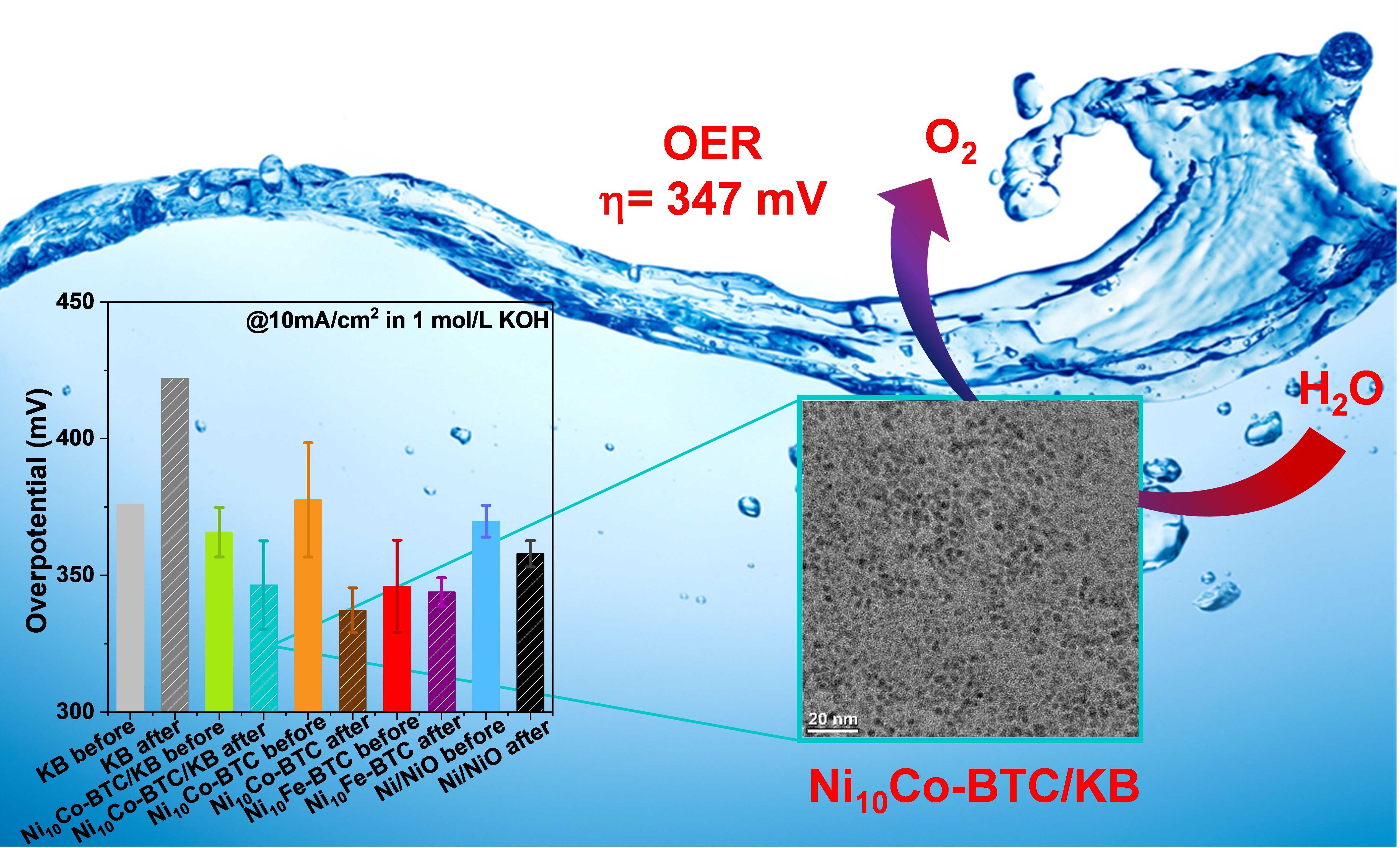
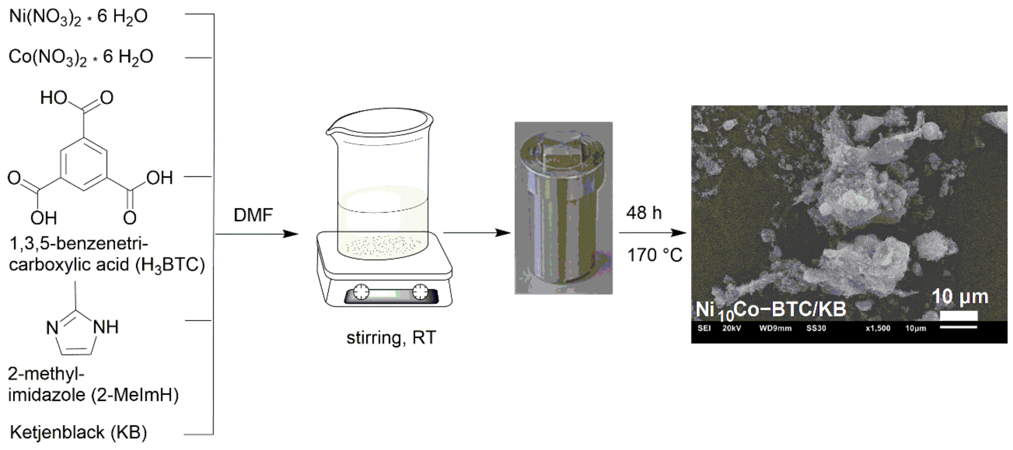
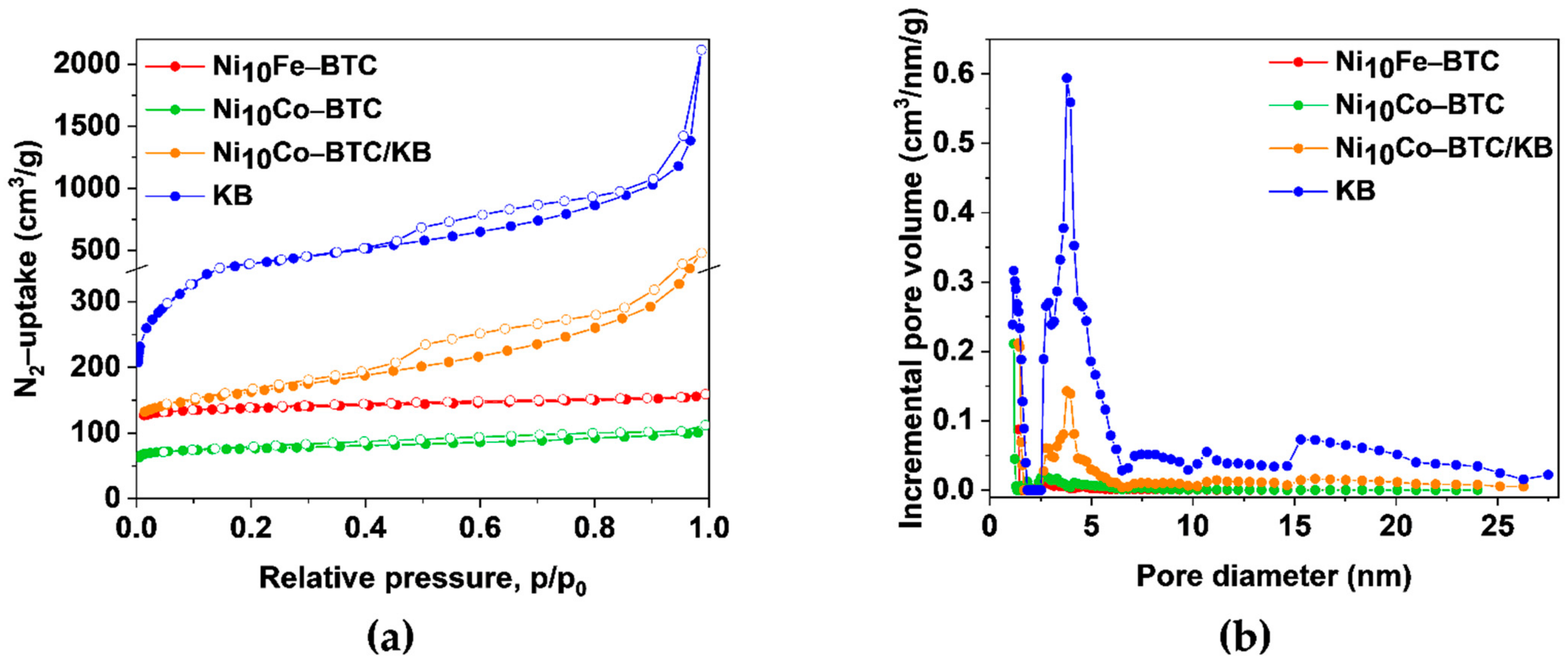
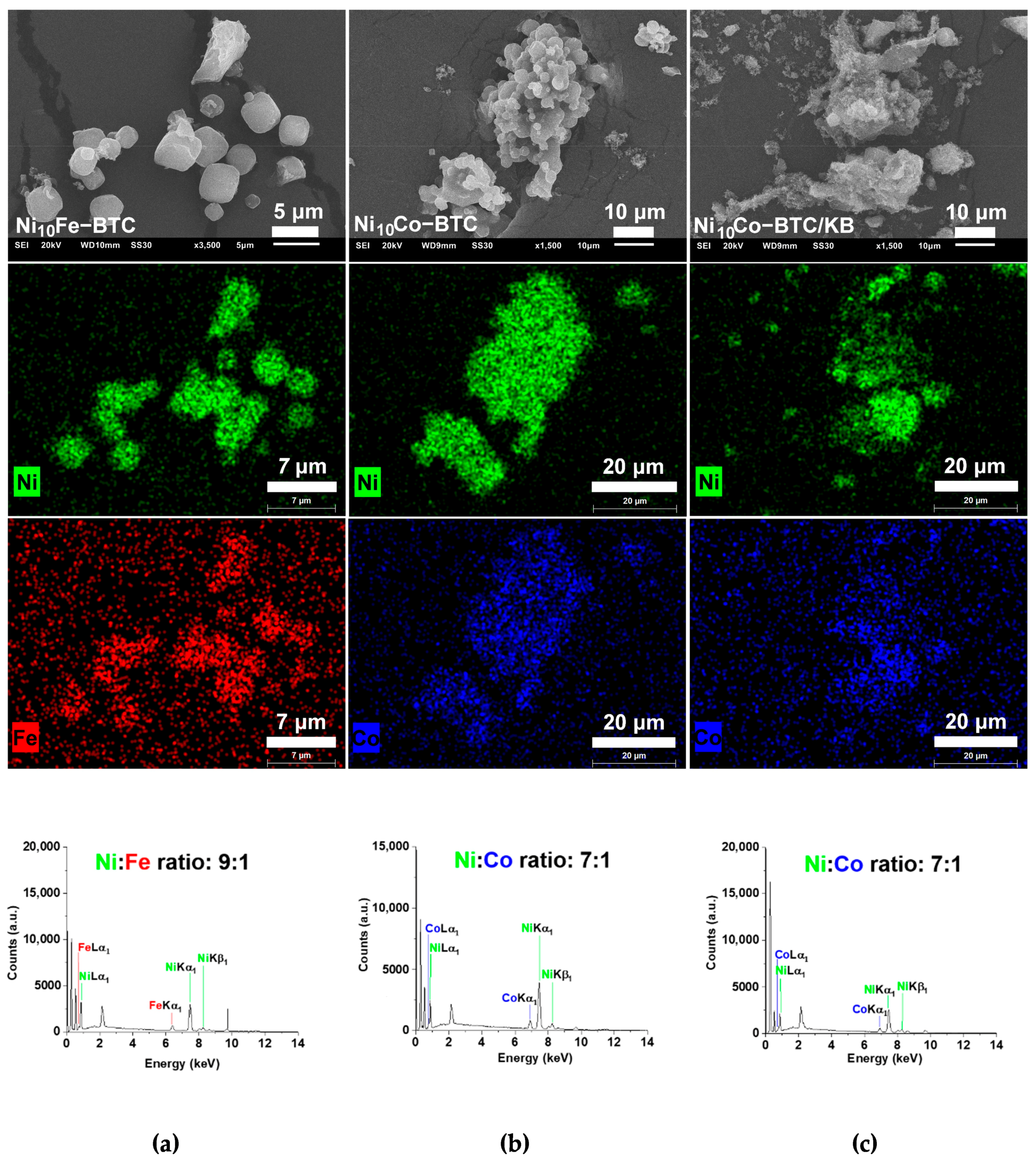
2.1. Synthesis and Characterization of the Ni-BTC Analogs

The Ni-BTC structure is identical to the Cu-BTC or HKUST-1 structure (HKUST = Hong Kong University of Science and Technology) [43] both are built by dinuclear metal(II)-secondary building units (SBUs), which are connected by BTC in a paddle-wheel fashion to a three-dimensional network of formula [Ni3(BTC)2] [43,44]. The composite of Ni10Co-BTC and KB, named Ni10Co-BTC/KB was generated through a facile MOF synthesis in the presence of ketjenblack (KB) in a one-step solvothermal reaction at 170 °C for 48 h from a mixture of Ni(NO3) 6 H2O, Co(NO3) 6 H2O (molar Ni:Co ratio 10:1), 1,3,5-benzenetricarboxylic acid (H3BTC), 2-methylimidazole (2-MeImH), and KB in N,N-dimethylformamide (DMF) (Figure 1). Ni10Co-BTC and Ni10Fe-BTC were synthesized for comparison. Ni-BTC and the mixed-metal analogs are obtained as the dimethylamine adduct [Ni3(BTC)2(Me2NH)3] at the axial metal position with Me2NH being a hydrolysis product of DMF [43] (from the CHN elemental analysis data in Table S1, Supporting Information (SI)).
A well-known phenomenon in mixed-metal MOF synthesis is that the incorporated metal ratio can differ from the starting material ratio and must be post-synthetically quantified. To quantify the amount of Co and Fe in the synthesized Ni10Co-BTC and Ni10Fe-BTC flame atomic absorption spectroscopy (AAS) was conducted post-synthetically, resulting in a molar Ni:Co ratio of 11:1 for Ni10Co-BTC and a molar Ni:Fe ratio of 11:1 for Ni10Fe-BTC (Table 1).
From the AAS determined metal wt.%, the mass fractions of the MOF in the KB composites were calculated as 67 wt.% Ni10Co-BTC together with 33 wt.% KB.
Powder X-ray diffraction (PXRD) patterns of Ni10Fe-BTC, Ni10Co-BTC, Ni10Co-BTC/KB, KB and a simulated diffraction pattern of Ni-BTC are illustrated in Figure 2a. The pristine MOF samples Ni10Fe-BTC and Ni10Co-BTC exhibit the same reflexes as the simulated pattern of Ni-BTC. The composite Ni10Co-BTC/KB also demonstrated a PXRD pattern, which agrees to the simulated pattern of Ni-BTC and also the pristine MOF Ni10Co-BTC. The aforementioned PXRD patterns show that the addition of amorphous KB in the synthesis did not influence the MOF crystal growth and structure significantly [45,46]. Apart from the reflexes of the simulated Ni-BTC MOF there are no additional reflexes in the diffraction patterns of the samples, which reveals that no iron or cobalt(oxy)hydroxides formed in the synthesis. This indicates that the second metal (iron or cobalt) was well incorporated into the structure of the Ni-BTC MOF. Pure KB displayed three broad diffraction peaks corresponding to the (100), (002), (101) planes of amorphous carbon [47,48].
Fourier transform infrared (FT-IR) spectra (Figure 2b) of the Ni-BTC analogs demonstrate the same characteristic bands (listed in Table S2, SI) which are in a good agreement with the literature [39]. A broad band in the region of 3600–3000 cm–1 and a band around 1650 cm−1 can be attributed to the stretching and bending vibrations of -OH group from adsorbed or coordinated water [43,49,50,51]. Characteristic vibrations of a Ni-O bond 577–460 cm−1 [51] and of carboxylate-groups 1617–1556 cm−1 (asymmetric vibration) and 1439–1364 cm−1 (symmetric vibration) can be observed in all samples [50,52]. Vibrations of a Fe-O bond are reported at 538 and 634 cm−1 and of a Fe2Ni-O bond at ca. 720 cm−1, which is also in the range of the vibration of a Co-O bond (725 cm−1) [53,54,55]. Fe-O could not be detected and the Fe2Ni-O and Co-O bonds are all in a similar range to each other and to aromatic vibrations (Table S2, SI).
The specific Brunauer-Emmett-Teller (BET) surface areas and pore volumes of the materials were derived from nitrogen-adsorption isotherms at 77 K (Figure 3a) and are given in Table S3, SI.
The BET surface areas of the Ni-BTC analogs (Ni10Fe-BTC: 555 m2/g, Ni10Co-BTC: 303 m2/g and Ni10Co-BTC/KB: 596 m2/g) are all in the range of reported values for neat Ni-BTC (Ni-BTCDMF/EtOH: 198 m2/g and 252 m2/g, Ni-BTCEtOH: 551 m2/g; Ni-BTC: 0.286 cm3/g) [56,57]. Ni10Fe-BTC and Ni10Co-BTC show a type I isotherm revealing their microporosity with a steep gas uptake at low relative pressure followed by a plateau [58,59,60]. KB is a porous carbon material with a BET surface area of 1415 m2/g, a pore volume of 1.59 cm3/g (Table S3, SI) and mesopores, which are mostly around 4 ± 2 nm (Figure 3b). The adsorption isotherm branch of KB is a composite of a type I and II isotherm and the desorption isotherm branch additionally displays a H4 hysteresis, both being often indicators for micro-mesoporous carbons [58]. The nitrogen sorption isotherm and BET-surface area of the composite Ni10Co-BTC/KB is a superposition of the isotherms of the MOF and KB components (Figure 3a). This superposition also holds for the pore-size distribution of the individual components in the composite (Figure 3b). The bimodal pore size distribution of Ni10Co-BTC/KB with maxima at ~2 nm and ~4 nm reflects the contributions from the MOF and KB. Consequently, the BET surface area and pore volume of the Ni10Co-BTC/KB composite with 596 m2/g and 0.45 cm3/g, respectively, are higher than the surface area and pore volume of neat Ni10Co-BTC (303 m2/g, 0.15 cm3/g) but still lower than the calculated BET surface area (670 m2/g) as determined from the sum of the mass-weighted S(BET) of KB (33 wt.%) and MOF (67 wt.%) (Equation (3) [34]):
S ( BET ) calc. = wt . %   of   KB 100   ×   S ( BET ) KB + wt . %   of   MOF 100 × S ( BET ) MOF
The slightly lower BET surface area can be due to pore blocking effects or formation of the MOF in the mesopores of KB, as evidenced by the large reduction of the incremental mesopore volume in Figure 3b.
Thermogravimetric analyses (TGA) under N2 atmosphere yield a similar curvature for all Ni-BTC analogs (Figure S1, SI). In the range of 30–320 °C the initial weight losses until decomposition can be attributed to the loss of crystal solvent molecules (DMF, H2O) incorporated in the cavities [61]. After complete solvent loss the BTC-linker together with the MOF structure decomposes around 350–600 °C (Lit. 337–450 °C) (mass change of 54–57 %, Figure S1, SI) [56,60]. The TGA curves are in agreement with reported curves for NiCo-BTC and Ni-BTC [35,43,60,61].
Scanning electron microscopy (SEM) images of Ni10Fe-BTC (Figure 4a) present spherical and cubic particles, which is in accordance with the literature [40]. Ni10Co-BTC (Figure 4b) has irregular shaped aggregates similar to reported Ni-BTC [40]. The KB particles (Figure S3, SI) are smaller than the MOF particles, and do not have a clearly defined shape. In the composite material Ni10Co-BTC/KB (Figure 4c) the MOF particles are covered by KB. SEM-energy-dispersive X-ray spectroscopy (EDX) was conducted for the mixed-metal MOFs (Figure 4 and Figure S2, SI) and KB (Figure S3, SI). For the mixed-metal MOFs SEM-EDX metal element mapping (Figure 4) reveals a good superposition of the two different metals. It is evident that the mapping of nickel and iron or cobalt of Ni10Fe-BTC and Ni10Co-BTC, respectively, is more visible than for Ni10Co-BTC/KB, where the KB partially covers and masks surface of the MOF particles.
The metal contents of the mixed-metal samples were quantified by SEM-EDX and atomic absorption spectroscopy (AAS) and are compared in Table 1. The SEM-EDX results are more indicative of the metal ratio of the surface of the samples and the AAS results quantify the metal ratio of the bulk samples. For the synthesis of all materials a starting molar ratio of 10:1 was used for nickel to iron or cobalt. Ni10Fe-BTC and Ni10Co-BTC give similar AAS results with a ratio of approximately 11:1 (Ni:Fe/Co), which is close to the used 10:1 molar ratio for the synthesis. The AAS of the composite material Ni10Co-BTC/KB results in a Ni:Co ratio of approximately 8:1, which is a little lower than the implemented molar ratio in the beginning.

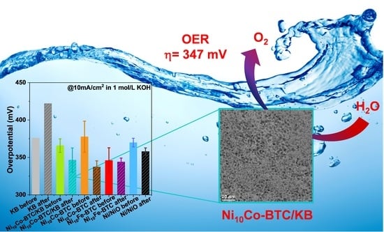
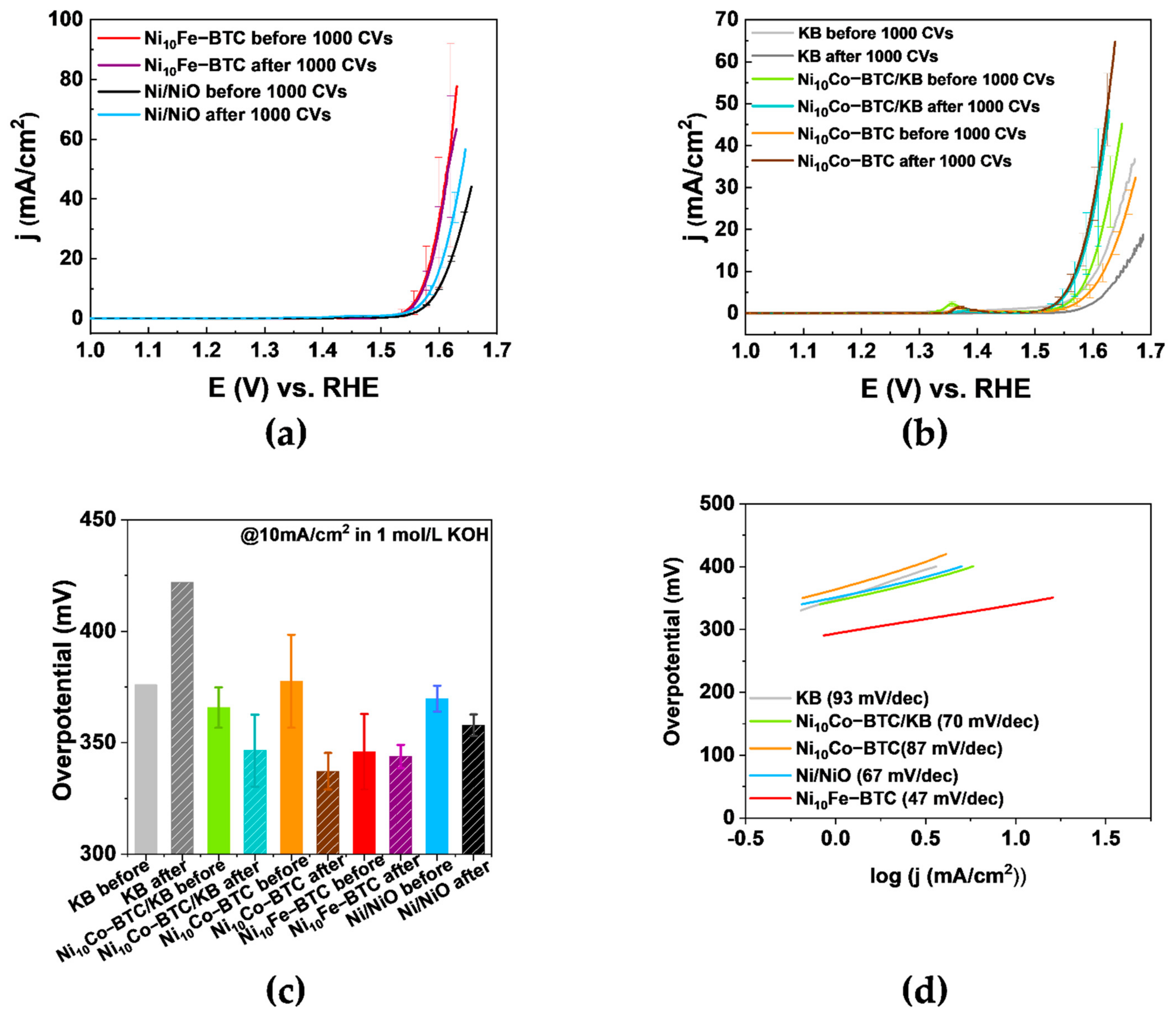
2.2. Electrocatalytical Results

The OER performance of all samples was checked using a three-electrode system with rotation disk electrode in 1 mol/L KOH electrolyte. The electrochemical kinetics of the samples were evaluated by comparison of the Tafel slopes derived from linear sweep voltammetry (LSV) curves after the activation. Apart from the overpotential and Tafel slope the stability of the electrocatalysts were examined by comparing the overpotential before and after 1000 cyclic voltammetry cycles (CVs). Details are given in the experimental section.
The LSV curves in Figure 5a,b show that Ni10Fe-BTC reaches the highest current density before the stability test in comparison to the reference commercial Ni/NiO nanoparticles, Ni10Co-BTC, Ni10Co-BTC/KB and KB. The LSV curves in Figure 5b display that the current density of Ni10Co-BTC/KB was higher than that of the pristine MOF or KB before the stability test, which could be due to a conductivity enhancement effect by the introduction of KB. After the stability test the achieved current density of the pristine MOF is higher than the composite and both are higher than the current density of KB. The current densities of Ni10Fe-BTC and of KB have declined after the stability test. Ni10Co-BTC, Ni10Co-BTC/KB and the commercial Ni/NiO nanoparticles reach a higher current density after the stability test. The peaks from 1.3 to 1.4 V vs. RHE in Figure 5b originated from the redox reaction of Ni2+/3+ [35,62,63]. The redox peaks are less visible for Ni10Fe-BTC, which is due to the well-known suppressor effect of Fe for the Ni2+/3+ oxidation [64,65,66]. The changed current densities before and after the 1000 CVs already depict that an activation is taking place in case of the NiCo samples and the Ni/NiO nanoparticles. The efficiency of an electrocatalyst is normally checked with the overpotential at a current density (j) of 10 mA/cm2, which relates to the approximate current density expected for a 10% efficient solar-to-fuel conversion device under sun illumination [13,67,68]. To have a more defined indicator the initial overpotential and the overpotential after the stability test to reach 10 mA/cm2 should be considered. Ni10Fe-BTC reaches 10 mA/cm2 with an initial overpotential of 346 mV and an overpotential of 344 mV after the stability test. The measurement done after the stability test shows nearly identical values, which indicates that the material is stable in its OER performance. The results show that Ni10Fe-BTC has a relatively good OER performance. The overpotentials needed to reach 10 mA/cm2 before and after the stability test and Tafel slopes for KB, Ni10Co-BTC/KB, Ni10Co-BTC and Ni/NiO nanoparticles including the results of Ni10Fe-BTC are listed in Table S4, SI. Ni10Co-BTC (η = 378 mV → 337 mV), Ni10Co-BTC/KB (η = 366 mV → 347 mV) MOF samples and the Ni/NiO nanoparticles (η = 370 mV → 358 mV) all give a decreasing overpotential, which indicates an activation of the materials and an increased OER activity. The improvement of the activity of the materials reveal that the prior activation (10 CVs) was not sufficient and it also can correlate with the formation of, for example, a highly OER active NiOOH layer [69]. Only KB demonstrated a higher overpotential afterwards (η = 376 mV → 422 mV). KB exhibits worse OER activity after 1000 cycles due to carbon corrosion at high potentials in alkaline conditions [70,71]. The carbon corrosion can also be the limiting factor of the composite, since after the 1000 CVs the Ni10Co-BTC-derived material provides the lowest overpotential with 337 mV. The Ni10Co-BTC/KB composite shows the best initial OER activity, but Ni10Co-BTC has a stronger activation after the stability test and consequently a higher activity.
The Tafel slopes (Figure 5d) of Ni10Fe-BTC (47 mV/dec), Ni10Co-BTC/KB (70 mV/dec), Ni10Co-BTC (87 mV/dec) and Ni/NiO nanoparticles (67 mV/dec) are in agreement with the reported values of Ni-BTC (71 mV/dec), FeNi10-BTC (60 mV/dec), Fe3Ni-BTC (49 mV/dec), FeNi-BTC (50 mV/dec) NiCo2O4 (Precursor: NiCo-BTC) (59.3 mV/dec) and Ni(OH)2 (65 mV/dec) [17,35,40]. The value of the Tafel slope can give insight into the rate determining step (rds) of the OER mechanism. Krasil’shchikov’s OER mechanism is one of the more widely known mechanisms, which is described by Equations (4)–(7) with the corresponding Tafel slopes b [72,73].
M + OH     MOH + e b = 120   mV / dec
MOH + OH   MO + e b = 60   mV / dec
  MO     MO + e b = 45   mV / dec
2 MO     2 M + O 2 b = 19   mV / dec
For Ni10Fe-BTC (47 mV/dec) Equation (6) appears to be the rds of the OER mechanism. The most likely rds of the OER mechanism of Ni10Co-BTC/KB (70 mV/dec) and Ni/NiO nanoparticles (67 mV/dec) seem to be Equation (5). The Tafel slope of Ni10Co-BTC (87 mV/dec) is in between the values of Equations (4) and (5), which makes it difficult to clearly assign it to one of the two reaction steps.
MOFs often act as sacrificial agents to generate structured carbon-based metal oxide materials as efficient electrocatalysts [27,32,35]. To test the stability of the synthesized MOF materials in the alkaline electrolyte Ni10Co-BTC, Ni10Co-BTC/KB and Ni10Fe-BTC were soaked in 1 mol/L KOH for 24 h.
The PXRD patterns of all three samples (Figure 6) display transitions of the MOF structures to their (oxy)hydroxides. Ni10Co-BTC and Ni10Co-BTC/KB (Figure 6a) exhibit structural changes to α-Ni(OH)2 (ICDD:38-0715), β-Ni(OH)2 (ICDD:14-0117), β-NiOOH (ICDD:06-0141) and/or γ-NiOOH (ICDD:06-0075) [74]. The relationship between these nickelhydroxides and oxidehydroxides is explained in the Supplementary Information. It is presently not possible, however, to quantify the components in a mixed α/β-Ni(OH)2 sample from XPS results [75]. According to literature [75] α- and β-Ni(OH)2 could be possibly distinguished from each other by FT-IR spectroscopy. FT-IR spectra for the samples after letting them soak in 1 mol/L KOH for 24 h only indicated also the formation of α- and β-Ni(OH)2, albeit without being able to differentiate between them (Figure S7 and Table S5 in the SI). The diffraction patterns for α-Co(OH)2 and γ-CoOOH match the given Ni(OH)2 and NiOOH diffraction patterns [76]. Similar to Ni10Co-BTC and Ni10Co-BTC/KB the PXRD pattern of Ni10Fe-BTC after 24 h in 1 mol/L KOH (Figure 6b) shows a clear loss of crystallinity of the material and indicates formation of α-Ni(OH)2 (ICDD:38-0715) and/or α-FeOOH (ICDD: 29-0713) [74,77]. The change in the structure of Ni10Co/Fe-BTC to Ni(OH)2, Co(OH)2 and/or to NiOOH, CoOOH and/or FeOOH is in agreement to reported observations [78]. The transition to their (oxy)hydroxides fits to the activation which could have been seen through the decrease of their overpotentials (Table S4, SI). Furthermore, transmission electron microscopy (TEM) images were made of the synthesized MOF samples before and after the electrochemical stability tests (1000 CVs). The TEM images (Figures S4–S6, SI) also indicate that a transition of the original MOF morphology takes place. The Ni10Co-BTC/KB TEM images (Figure S6, SI) illustrate that the larger MOF particle transformed into nanoparticles. The homogenous Ni10Co-BTC MOF particle (Figure S5, SI) changed into a carbon-based material, which contains metal (oxy)hydroxides nanoparticles. The lattice spacings of both NiCo samples (Figures S5d and S6c) could be obtained. The values of the lattice spacings fit to values of reported Ni(OH)2 [79] and Co(OH)2, which was formed during electrochemical tests of the MOF ZIF-67 [80]. For Ni10Fe-BTC (Figure S4, SI) a loss of the former cubic shape of the particle can be observed and out of the resulting new morphology no lattice spacings could be gained. The changed morphology of all samples corroborates the structural changes, which could be seen through the stability test of the synthesized materials in the alkaline electrolyte.

3. Materials and Methods

3.1. Materials

The used chemicals were obtained from commercial sources and no further purification was carried out. Ketjenblack EC 600 JD was purchased from AkzoNobel, Amsterdam. The Netherlands.

3.2. Synthesis of the Ni-BTC Analogs

Synthesis of Ni10Fe-BTC: Ni10Fe-BTC was synthesized according to the literature [40]. 48 mg (0.11 mmol) Fe(NO3)3* 9 H2O, 349 mg (1.2 mmol) Ni(NO3)2* 6 H2O, 205 mg (0.98 mmol) H3BTC and 55 mg (0.67 mmol) 2-MeImH were dissolved in 15 mL DMF at room temperature (RT) and stirred for 30 min. The prepared solution was transferred into a Teflon-lined stainless-steel autoclave and then heated to 170 °C for 48 h. The resulting dark olive-green precipitate was centrifuged (25 min, 5000 rpm). The precipitate was washed one time with DMF and two times with EtOH and centrifuged again (15 min, 6000 rpm). The product was dried overnight in a vacuum drying cabinet at 90 °C and <50 mbar.
Yield (Ni10Fe-BTC): 276 mg
Synthesis of Ni10Co-BTC and Ni10Co-BTC/KB: Ni10Co-BTC and Ni10Co-BTC/KB were synthesized according to the literature with some modifications [40]. Varying from this synthesis procedure Co(NO3)2* 6 H2O was used instead of Fe(NO3)3* 9 H2O for the synthesis of Ni10Co-BTC and Ni10Co-BTC/KB.
For the Ni10Co-BTC sample 35 mg (0.12 mmol) Co(NO3)2* 6 H2O, 349 mg (1.2 mmol), Ni(NO3)2* 6 H2O, 205 mg (0.98 mmol) H3BTC and 55 mg (0.67 mmol) 2-MeImH were dissolved in 20 mL DMF at RT and stirred for 30 min. For the Ni10Co-BTC/KB sample the same amounts were used and 70 mg KB additionally added. The prepared solution was transferred into a Teflon-lined stainless-steel autoclave and then heated to 170 °C for 48 h. The resulting dark olive-green (Ni10Co-BTC) and black (Ni10Co-BTC/KB) precipitates were centrifuged (25 min, 5000 rpm). The precipitates were washed for one time with DMF and for two times with EtOH and centrifuged again (15 min, 6000 rpm). The products were dried overnight in a vacuum drying cabinet at 90 °C and <50 mbar.
Yield (Ni10Co-BTC): 328 mg
Yield (Ni10Co-BTC/KB): 357 mg

3.3. Materials Characterization

Powder X-ray diffraction (PXRD) measurements were performed at ambient temperature on a Bruker D2 Phaser powder diffractometer with a power of 300 W and an acceleration voltage of 30 kV at 10 mA using Cu-Kα radiation (λ = 1.5418 Å). The diffractograms were obtained on a low background flat silicon sample holder and evaluated with the Match 3.11 software. The samples were measured in the range from 5 to 50° 2θ with a scan speed of 2 s/step and 0.057° (2θ) step size.
Fourier transform infrared spectroscopy (FT-IR) spectra were recorded in KBr mode on a Bruker TENSOR 37 IR spectrometer in the range of 4000–400 cm−1.
Nitrogen sorption measurements were performed with a Nova 4000e from Quantachrome at 77 K. The sorption isotherms were evaluated with the NovaWin 11.03 software. Prior to the measurement the materials were first degassed under vacuum (<10−2 mbar) at 120 °C for 5 h. Brunauer–Emmett–Teller (BET) surface areas were determined from the N2-sorption adsorption isotherms and the pore size distributions were derived by non-local density functional theory (NLDFT) calculations based on N2 at 77 K on carbon with slit/cylindrical pores.
Thermogravimetric analyses (TGA) were carried out with a Netzsch TG 209 F3 Tarsus device equipped with an Al crucible with a heating rate of 5 K/min under nitrogen atmosphere.
CHN elemental analyses were conducted with a Vario Mirco Cube from Elementar Analysentechnik.
Flame atomic absorption spectroscopy (AAS) was conducted with a PinAAcle 900T from PerkinElmer. Weighted samples were heated to dryness with 15 mL of aqua regia for two times and afterwards stirred with 10 mL of aqua regia overnight. The solution was carefully filtered and diluted with Millipore water to a volume of 25 mL. The resulting solutions were further diluted with Millipore water (1:50) for the AAS measurements.
Scanning electron microscopy (SEM) images were collected with a JEOL JSM-6510 LV QSEM advanced electron microscope with a LaB6 cathode at 20 kV. The microscope was equipped with a Bruker Xflash 410 silicon drift detector and the Bruker ESPRIT software for energy-dispersive X-ray (EDX) analysis which was used to record EDX spectra and EDX mapping. The small amount of Cu, Zn and Au found in the EDX spectra are due to the brass sample holder and the sputtering of the sample with gold prior to the investigation.
Transmission electron microscopy (TEM) images of the MOF samples before the electrochemical tests were recorded on a FEI Tecnai G2 F20 electron microscope operated at 200 kV accelerating voltage equipped with a Gatan UltraScan 1000P detector. TEM samples were prepared by drop-casting the diluted material on 200 μm carbon-coated copper grids. TEM images of the samples after the electrochemical tests were obtained using a FEI Titan, 80–300 TEM with a Cs corrector for the objective lens (CEOS GmbH) operated at 300 kV. After the electrochemical test the electrode was rinsed in isopropanol and sonicated until all the layers from the surface of the electrode were dissolved into the solution. Again, the TEM samples were prepared by drop-casting the solution onto the TEM grid. Particle sizes and size distribution were determined manually using the Gatan Digital Micrograph software. For the size distribution over 150 individual particles were analyzed.

3.4. Electrocatalytic Measurements

The electrocatalytic OER measurements were conducted with a SP-150 Potentiostat form BioLogic Science Instruments and with a three-electrode setup. As reference electrode a mercury/mercury oxide (Hg/HgO) electrode was used. As counter electrode a Pt wire was used. As working electrode, a rotating disc electrode (RDE), here a glassy carbon electrode (GCE), was used. For the electrocatalyst inks 8 mg of electrocatalyst was dispersed in 1.5 mL isopropanol, 0.5 mL deionized water, and 20 μL Nafion (5 wt.%) and sonicated for 40 min. Catalyst loading was 0.2 mg/cm2 by drop casting 10 μL ink on the GC surface (geometric area of 0.196 cm2). All the powders dispersed well, forming a stable and homogeneous ink. After drying, the film fully covered the GC electrode. All the electrochemical measurements were conducted in 1 mol/L concentrated Ar-saturated KOH electrolyte, which has been purged with O2 for 20 min prior to the OER experiments, with a rotation speed of 1600 rpm at RT. An activation protocol was used before the LSV measurements by cycling the working electrode between 1.0 V and 1.7 V vs. RHE at a scan rate of 100 mV/s for 10 cycles. The LSV polarization curves were recorded in a potential range of 1.0 to 1.7 V vs. RHE at a sweep rate of 5 mV/s without iR correction. The potential applied to the ohmic resistance was extracted later manually. The cycling stability was measured by comparing LSV curves before and after 1000 cycles between 1.0–1.7 V with a scan rate of 100 mV/s.
The measured potentials (vs. Hg/HgO) were converted in potentials vs. RHE with the following Equation (8) [81]:
ERHE = E(Hg/HgO) + 0.059pH + E°(Hg/HgO)
with ERHE = converted potential vs. RHE, E(Hg/HgO) = measured potential and E°(Hg/HgO) = standard potential of the Hg/HgO reference electrode.
The overpotential was calculated as shown in Equation (1): ηOER = ERHE − E° (1.23 V). To reduce the experimental contingency error, at least three repeated measurements were carried out for a sample and the average curves with their error bars were compared in the figures. The OER performance of MOF samples were compared with commercial Ni/NiO nanoparticles (Alfa Aesar, Heysham, UK; VWR, International GmbH, Darmstadt, Germany) and KB (AkzoNobel, Amsterdam, The Netherlands).

4. Conclusions

Different mixed-metal Ni-BTC analogs with cobalt and iron doping were synthesized, characterized, tested for their performance in the OER and compared to the reference of Ni/NiO nanoparticles and KB. The pristine MOFs Ni10Co-BTC and Ni10Fe-BTC, as well as the composite Ni10Co-BTC/KB could be prepared easily through a one-step solvothermal reaction. To compensate the shortcoming of low MOF conductivity for electrocatalysis, the highly porous and conductive carbon material KB was added, which can also support the transport of electrolyte ions and evolved gases. The MOF electrocatalysts are not stable under the implemented alkaline conditions for the electrocatalytic measurements, which again emphasizes that MOFs can be regarded as sacrificial agents. Nevertheless, the resulting, stabilized materials all evince good performances in the OER. Comparing the overpotentials of Ni10Co-BTC (η = 378 mV) and Ni10Co-BTC/KB (η = 366 mV) before the stability test, the composite shows a better performance for the OER, but afterward, the Ni10Co-BTC-derived electrocatalyst exhibits a lower overpotential (337 mV) than the Ni10Co-BTC/KB-derived electrocatalyst (347 mV). This illustrates that the conductivity, which could have been increased by introducing KB, is not the key factor limiting the OER activity of the Ni10Co-BTC-derived electrocatalyst. However, a clearly positive effect of KB in the Ni10Co-BTC/KB-derived material is a decreased Tafel slope with 70 mV dec−1 in comparison to the Ni10Co-BTC-derived material with 87 mV dec−1, which indicates a more favorable kinetics of the OER for the composite-derived material. The Ni10Fe-BTC-dervied electrocatalyst remains the most stable material in the electrochemical OER performance (η = 346 mV → 344 mV) and has the lowest Tafel slope of 47 mV dec−1, showing that the activity of Ni-electrocatalysts can be improved to some extent with incorporated iron. The results of the Tafel analysis show that the introduction of KB in the Ni10Co-BTC MOF facilitates to overcome the kinetic barrier of the complex four electron-proton coupled OER transfer process. The composite material Ni10Co-BTC/KB and the presented protocol give insight into the possibility of combining MOFs, as sacrificial agents, with KB to generate new MOF-based electrocatalysts for electrocatalytic reactions. Further research should now be conducted to investigate potential other nickel-metal combinations to optimize the electrocatalytic performance.

Supplementary Materials

The following supporting information can be downloaded online. Table S1. Elemental analysis of the MOF samples. Table S2. Assignments of IR-bands of Ni-BTC analogs (cm−1). Table S3. BET-surface areas and total pore volumes of the Ni-BTC analogs. Table S4. Overpotentials (at 10 mA/cm2) and Tafel slopes for Ni10Fe-BTC, Ni10Co-BTC, Ni10Co-BTC/KB, KB and Ni/NiO nanoparticles done with a GCE (loading: 0.2 mg/cm2) with a scan rate of 5 mV/s in a 1.0 mol/L KOH electrolyte. Figure S1. TGA curves of (a) Ni10Fe-BTC, (b) Ni10Co-BTC, (c) Ni10Co-BTC/KB and (d) KB under N2 atmosphere with a heating rate of 5 K/min. Figure S2. SEM-EDX spectra of (a) Ni10Fe-BTC, (b) Ni10Co-BTC and (c) Ni10Co-BTC/KB. Figure S3. (a,b) SEM images and (c) SEM-EDX spectra of KB. Figure S4. TEM images of Ni10Fe-BTC (a) before (shown particle size: 3.1 μm) and (b–d) after 1000 CVs. Figure S5. TEM images of Ni10Co-BTC (a) before and (b–d) after 1000 CVs (shown particle size in (b): 2.8 μm; displayed particles in (c) give the average diameter of 20 nm ± 9 nm; (d) the lattice spacings and grain boundaries are illustrated in red and red lines, respectively). Figure S6. TEM images of Ni10Co-BTC/KB (a) before (shown particle size: 4.4 μm) and (b,c) after 1000 CVs ((c) the lattice spacings and grain boundaries are illustrated in red and red lines, respectively.) and (d) histogram of Ni10Co-BTC/KB after 1000 CVs determined from (b) give the average diameter of 5 nm ± 1 nm (1σ). Scheme S1. Schematic relation between β -Ni(OH)2, α-Ni(OH)2, β-NiOOH and γ-NiOOH. Figure S7. FT-IR spectra of (a) Ni10Co-BTC after 24 h in 1 mol/L KOH (dark green) and (b) comparison with Ni10Co-BTC (green), (c) Ni10Co-BTC/KB after 24 h in 1 mol/L KOH (brown) and (d) comparison with Ni10Co-BTC/KB (orange), (e) Ni10Fe-BTC after 24 h in 1 mol/L KOH (purple) and (f) comparison with Ni10Fe-BTC (red). Table S5. Assignments of IR-bands of Ni-BTC analogs after 24 h in 1 mol/L KOH (cm−1). References [82,83,84] are cited in the supplementary materials.

Author Contributions

Conceptualization, C.J. and L.S.; Methodology, L.S.; Validation, L.S. and M.S.; Formal analysis, L.S.; Investigation, L.S., W.J., M.S., A.S., D.W. and L.R.; Resources, C.J.; Data Curation, L.S.; Writing—Original Draft, L.S.; Writing—Review & Editing, C.J., W.J. and M.S.; Visualization, L.S.; Supervision, C.J.; Project administration, C.J.; Funding acquisition, C.J. All authors have read and agreed to the published version of the manuscript.

Funding

The research of C.J. was supported by a joint National Natural Science Foundation of China–Deutsche Forschungsgemeinschaft (NSFC-DFG) project (DFG JA466/39-1).

Institutional Review Board Statement

Not applicable.

Informed Consent Statement

Not applicable.

Data Availability Statement

The data presented in this study are available on request from the corresponding author.

Conflicts of Interest

The authors declare that they have no known competing financial interest or personal relationships that could have appeared to influence the work reported in this paper.

References

  1. IEA. CO2 Emissions from Fuel Combustion 2019—Highlights; IEA: Paris, France, 2019. [Google Scholar]
  2. Özturk, S.; Xiao, Y.-X.; Dietrich, D.; Giesen, B.; Barthel, J.; Ying, J.; Yang, X.-Y.; Janiak, C. Nickel nanoparticles supported on a covalent triazine framework as electrocatalyst for oxygen evolution reaction and oxygen reduction reactions. Beilstein J. Nanotechnol. 2020, 11, 770–781. [Google Scholar] [CrossRef]
  3. Seh, Z.W.; Kibsgaard, J.; Dickens, C.F.; Chorkendorff, I.; Nørskov, J.K.; Jaramillo, T.F. Combining theory and experiment in electrocatalysis: Insights into materials design. Science 2017, 355, eaad4998. [Google Scholar] [CrossRef] [PubMed] [Green Version]
  4. Roger, I.; Shipman, M.A.; Symes, M.D. Earth-abundant catalysts for electrochemical and photoelectrochemical water splitting. Nat. Rev. Chem. 2017, 1, 3. [Google Scholar] [CrossRef]
  5. Zheng, S.; Li, X.; Yan, B.; Hu, Q.; Xu, Y.; Xiao, X.; Xue, H.; Pang, H. Transition-Metal (Fe, Co, Ni) Based Metal-Organic Frameworks for Electrochemical Energy Storage. Adv. Energy Mater. 2017, 7, 1602733. [Google Scholar] [CrossRef]
  6. Zhuang, L.; Ge, L.; Yang, Y.; Li, M.; Jia, Y.; Yao, X.; Zhu, Z. Ultrathin Iron-Cobalt Oxide Nanosheets with Abundant Oxygen Vacancies for the Oxygen Evolution Reaction. Adv. Mater. 2017, 29, 1606793. [Google Scholar] [CrossRef] [PubMed]
  7. Han, L.; Dong, S.; Wang, E. Transition-Metal (Co, Ni, and Fe)-Based Electrocatalysts for the Water Oxidation Reaction. Adv. Mater. 2016, 28, 9266–9291. [Google Scholar] [CrossRef] [PubMed]
  8. Jiao, Y.; Zheng, Y.; Jaroniec, M.; Qiao, S.Z. Design of electrocatalysts for oxygen- and hydrogen-involving energy conversion reactions. Chem. Soc. Rev. 2015, 44, 2060–2086. [Google Scholar] [CrossRef] [PubMed]
  9. Tahir, M.; Pan, L.; Idrees, F.; Zhang, X.; Wang, L.; Zou, J.-J.; Wang, Z.L. Electrocatalytic oxygen evolution reaction for energy conversion and storage: A comprehensive review. Nano Energy 2017, 37, 136–157. [Google Scholar] [CrossRef]
  10. Bandal, H.; Koteshwara Reddy, K.; Chaugule, A.; Kim, H. Iron-based heterogeneous catalysts for oxygen evolution reaction; change in perspective from activity promoter to active catalyst. J. Power Sources 2018, 395, 106–127. [Google Scholar] [CrossRef]
  11. Wang, J.; Cui, W.; Liu, Q.; Xing, Z.; Asiri, A.M.; Sun, X. Recent Progress in Cobalt-Based Heterogeneous Catalysts for Electrochemical Water Splitting. Adv. Mater. 2016, 28, 215–230. [Google Scholar] [CrossRef]
  12. Suen, N.-T.; Hung, S.-F.; Quan, Q.; Zhang, N.; Xu, Y.-J.; Chen, H.M. Electrocatalysis for the oxygen evolution reaction: Recent development and future perspectives. Chem. Soc. Rev. 2017, 46, 337–365. [Google Scholar] [CrossRef] [PubMed]
  13. Wei, C.; Rao, R.R.; Peng, J.; Huang, B.; Stephens, I.E.L.; Risch, M.; Xu, Z.J.; Shao-Horn, Y. Recommended Practices and Benchmark Activity for Hydrogen and Oxygen Electrocatalysis in Water Splitting and Fuel Cells. Adv. Mater. 2019, 31, 1806296. [Google Scholar] [CrossRef] [PubMed]
  14. Farid, S.; Ren, S.; Hao, C. MOF-derived metal/carbon materials as oxygen evolution reaction catalysts. Inorg. Chem. Commun. 2018, 94, 57–74. [Google Scholar] [CrossRef]
  15. Anantharaj, S.; Ede, S.R.; Karthick, K.; Sankar, S.S.; Sangeetha, K.; Karthik, P.E.; Kundu, S. Precision and correctness in the evaluation of electrocatalytic water splitting: Revisiting activity parameters with a critical assessment. Energy Environ. Sci. 2018, 11, 744–771. [Google Scholar] [CrossRef]
  16. Li, Y.; Du, X.; Huang, J.; Wu, C.; Sun, Y.; Zou, G.; Yang, C.; Xiong, J. Recent Progress on Surface Reconstruction of Earth- Abundant Electrocatalysts for Water Oxidation. Small 2019, 15, 1901980. [Google Scholar] [CrossRef]
  17. Shinagawa, T.; Garcia-Esparza, A.T.; Takanabe, K. Insight on Tafel slopes from a microkinetic analysis of aqueous electrocatalysis for energy conversion. Sci. Rep. 2015, 5, 13801. [Google Scholar] [CrossRef] [Green Version]
  18. Hamann, C.H.; Vielstich, W. Elektrochemie, 4 ed.; Wiley-VCH: Weinheim, Germany, 2005. [Google Scholar]
  19. Lee, Y.; Suntivich, J.; May, K.J.; Perry, E.E.; Shao-Horn, Y. Synthesis and Activities of Rutile IrO2 and RuO2 Nanoparticles for Oxygen Evolution in Acid and Alkaline Solutions. J. Phys. Chem. Lett. 2012, 3, 399–404. [Google Scholar] [CrossRef] [PubMed]
  20. Pi, Y.; Zhang, N.; Guo, S.; Guo, J.; Huang, X. Ultrathin Laminar Ir Superstructure as Highly Efficient Oxygen Evolution Electrocatalyst in Broad pH Range. Nano Lett. 2016, 16, 4424–4430. [Google Scholar] [CrossRef]
  21. Zhao, P.; Hua, X.; Xu, W.; Luo, W.; Chen, S.; Cheng, G. Metal–organic framework-derived hybrid of Fe3C nanorod-encapsulated, N-doped CNTs on porous carbon sheets for highly efficient oxygen reduction and water oxidation. Catal. Sci. Technol. 2016, 6, 6365–6371. [Google Scholar] [CrossRef]
  22. Yang, D.; Chen, Y.; Su, Z.; Zhang, X.; Zhang, W.; Srinivas, K. Organic carboxylate-based MOFs and derivatives for electrocatalytic water oxidation. Coord. Chem. Rev. 2021, 428, 213619. [Google Scholar] [CrossRef]
  23. Zhu, Y.P.; Guo, C.; Zheng, Y.; Qiao, S.-Z. Surface and Interface Engineering of Noble-Metal-Free Electrocatalysts for Efficient Energy Conversion Processes. Acc. Chem. Res. 2017, 50, 915–923. [Google Scholar] [CrossRef] [PubMed]
  24. Xiao, Q.; Zhang, Y.; Guo, X.; Jing, L.; Yang, Z.; Xue, Y.; Yan, Y.-M.; Sun, K. A high-performance electrocatalyst for oxygen evolution reactions based on electrochemical post-treatment of ultrathin carbon layer coated cobalt nanoparticles. Chem. Commun. 2014, 50, 13019–13022. [Google Scholar] [CrossRef] [PubMed]
  25. Saha, S.; Ganguli, A.K. FeCoNi Alloy as Noble Metal-Free Electrocatalyst for Oxygen Evolution Reaction (OER). ChemistrySelect 2017, 2, 1630–1636. [Google Scholar] [CrossRef]
  26. Jin, S. How to Effectively Utilize MOFs for Electrocatalysis. ACS Energy Lett. 2019, 4, 1443–1445. [Google Scholar] [CrossRef] [Green Version]
  27. Shao, Q.; Yang, J.; Huang, X. The Design of Water Oxidation Electrocatalysts from Nanoscale Metal–Organic Frameworks. Chem. Eur. J. 2018, 24, 15143–15155. [Google Scholar] [CrossRef]
  28. Janiak, C.; Vieth, J.K. MOFs, MILs and more: Concepts, properties and applications for porous coordination networks (PCNs). New J. Chem. 2010, 34, 2366–2688. [Google Scholar] [CrossRef]
  29. Batten, S.R.; Champness, N.R.; Chen, X.-M.; Garcia-Martinez, J.; Kitagawa, S.; Öhrström, L.; O’Keeffe, M.; Paik Suh, M.; Reedijk, J. Terminology of metal–organic frameworks and coordination polymers (IUPAC Recommendations 2013). Pure Appl. Chem. 2013, 85, 1715–1724. [Google Scholar] [CrossRef] [Green Version]
  30. Aiyappa, H.B.; Masa, J.; Andronescu, C.; Muhler, M.; Fischer, R.A.; Schuhmann, W. MOFs for Electrocatalysis: From Serendipity to Design Strategies. Small Methods 2019, 3, 1800415. [Google Scholar] [CrossRef] [Green Version]
  31. Jiao, L.; Wang, Y.; Jiang, H.-L.; Xu, Q. Metal–Organic Frameworks as Platforms for Catalytic Applications. Adv. Mater. 2018, 30, 1703663. [Google Scholar] [CrossRef]
  32. Wang, H.-F.; Chen, L.; Pang, H.; Kaskel, S.; Xu, Q. MOF-derived electrocatalysts for oxygen reduction, oxygen evolution and hydrogen evolution reactions. Chem. Soc. Rev. 2020, 49, 1414–1448. [Google Scholar] [CrossRef]
  33. Frydendal, R.; Paoli, E.A.; Knudsen, B.P.; Wickman, B.; Malacrida, P.; Stephens, I.E.L.; Chorkendorff, I. Benchmarking the stability of oxygen evolution reaction catalysts: The importance of monitoring mass losses. ChemElectroChem 2014, 1, 2075–2081. [Google Scholar] [CrossRef] [Green Version]
  34. Özturk, S.; Moon, G.-H.; Spiess, A.; Budiyanto, E.; Roitsch, S.; Tüysüz, H.; Janiak, C. A Highly-Efficient Oxygen Evolution Electrocatalyst Derived from a Metal-Organic Framework and Ketjenblack Carbon Material. ChemPlusChem 2021, 86, 1106–1115. [Google Scholar] [CrossRef] [PubMed]
  35. Li, Z.; Gu, A.; He, X.; Lv, H.; Wang, L.; Lou, Z.; Zhou, Q. Rod bundle-like nickel cobaltate derived from bimetal-organic coordination complex as robust electrocatalyst for oxygen evolution reaction. Solid State Ion. 2019, 331, 37–42. [Google Scholar] [CrossRef]
  36. Jahan, M.; Liu, Z.; Loh, K.P. A Graphene Oxide and Copper-Centered Metal Organic Framework Composite as a Tri-Functional Catalyst for HER, OER, and ORR. Adv. Funct. Mater. 2013, 23, 5363–5372. [Google Scholar] [CrossRef]
  37. Li, J.; Zhou, N.; Song, J.; Fu, L.; Yan, J.; Tang, Y.; Wang, H. Cu–MOF-Derived Cu/Cu2O Nanoparticles and CuNxCy Species to Boost Oxygen Reduction Activity of Ketjenblack Carbon in Al–Air Battery. ACS Sustain. Chem. Eng. 2018, 6, 413–421. [Google Scholar] [CrossRef]
  38. Deng, X.; Özturk, S.; Weidenthaler, C.; Tuysuz, H. Iron-Induced Activation of Ordered Mesoporous Nickel Cobalt Oxide Electrocatalyst for the Oxygen Evolution Reaction. ACS Appl. Mater. Interfaces 2017, 9, 21225–21233. [Google Scholar] [CrossRef]
  39. Wang, L.; Wu, Y.; Cao, R.; Ren, L.; Chen, M.; Feng, X.; Zhou, J.; Wang, B. Fe/Ni Metal–Organic Frameworks and Their Binder-Free Thin Films for Efficient Oxygen Evolution with Low Overpotential. ACS Appl. Mater. Interfaces 2016, 8, 16736–16743. [Google Scholar] [CrossRef]
  40. Zheng, F.; Zhang, Z.; Xiang, D.; Li, P.; Du, C.; Zhuang, Z.; Li, X.; Chen, W. Fe/Ni bimetal organic framework as efficient oxygen evolution catalyst with low overpotential. J. Colloid Interface Sci. 2019, 555, 541–547. [Google Scholar] [CrossRef]
  41. Li, D.; Liu, H.; Feng, L. A Review on Advanced FeNi-Based Catalysts for Water Splitting Reaction. Energy Fuels 2020, 34, 13491–13522. [Google Scholar] [CrossRef]
  42. Zhai, Z.-M.; Yang, X.-G.; Yang, Z.-T.; Lu, X.-M.; Ma, L.-F. Trinuclear Ni(II) oriented highly dense packing and π-conjugation degree of metal–organic frameworks for efficient water oxidation. CrystEngComm 2019, 21, 5862–5866. [Google Scholar] [CrossRef]
  43. Maniam, P.; Stock, N. Investigation of Porous Ni-Based Metal-Organic Frameworks Containing Paddle-Wheel Type Inorganic Building Units via High-Throughput Methods. Inorg. Chem. 2011, 50, 5085–5097. [Google Scholar] [CrossRef] [PubMed]
  44. Furukawa, H.; Go, Y.B.; Ko, N.; Park, Y.K.; Uribe-Romo, F.J.; Kim, J.; O’Keeffe, M.; Yaghi, O.M. Isoreticular Expansion of Metal-Organic Frameworks with Triangular and Square Building Units and the Lowest Calculated Density for Porous Crystals. Inorg. Chem. 2011, 50, 9147–9152. [Google Scholar] [CrossRef] [PubMed]
  45. Forgan, R.S. Modulated self-assembly of metal–organic frameworks. Chem. Sci. 2020, 11, 4546–4562. [Google Scholar] [CrossRef] [PubMed] [Green Version]
  46. Wang, C.; Zhou, M.; Ma, Y.; Tan, H.; Wang, Y.; Li, Y. Hybridized Polyoxometalate-Based Metal–Organic Framework with Ketjenblack for the Nonenzymatic Detection of H2O2. Chem. Asian, J. 2018, 13, 2054–2059. [Google Scholar] [CrossRef]
  47. Ramaraghavulu, R.; Rao, V.K.; Devarayapalli, K.C.; Yoo, K.; Nagajyothi, P.C.; Shim, J. Green synthesized AgNPs decorated on Ketjen black for enhanced catalytic dye degradation. Res. Chem. Intermed. 2021, 47, 637–648. [Google Scholar] [CrossRef]
  48. Li, K.; Liu, Q.; Cheng, H.; Hu, M.; Zhang, S. Classification and carbon structural transformation from anthracite to natural coaly graphite by XRD, Raman spectroscopy, and HRTEM. Spectrochim. Acta Part A 2021, 249, 119286. [Google Scholar] [CrossRef] [PubMed]
  49. Meier, H.; Bienz, S.; Bigler, L.; Fox, T. Spektroskopische Methoden in der Organischen Chemie, 8th ed.; Georg Thieme: Stuttgart, Germany, 2011. [Google Scholar]
  50. Wu, Y.; Song, X.; Li, S.; Zhang, J.; Yang, X.; Shen, P.; Gao, L.; Wei, R.; Zhang, J.; Xiao, G. 3D-monoclinic M–BTC MOF (M = Mn, Co, Ni) as highly efficient catalysts for chemical fixation of CO2 into cyclic carbonates. J. Ind. Eng. Chem. 2018, 58, 296–303. [Google Scholar] [CrossRef]
  51. Maruthapandian, V.; Kumaraguru, S.; Mohan, S.; Saraswathy, V.; Muralidharan, S. An Insight on the Electrocatalytic Mechanistic Study of Pristine Ni MOF (BTC) in Alkaline Medium for Enhanced OER and UOR. ChemElectroChem 2018, 5, 2795–2807. [Google Scholar] [CrossRef]
  52. Yaghi, O.M.; Li, H.; Groy, T.L. Construction of Porous Solids from Hydrogen-Bonded Metal Complexes of 1,3,5-Benzenetricarboxylic Acid. J. Am. Chem. Soc. 1996, 118, 9096–9101. [Google Scholar] [CrossRef]
  53. Vuong, G.-T.; Pham, M.-H.; Do, T.-O. Direct synthesis and mechanism of the formation of mixed metal Fe2Ni-MIL-88B. CrystEngComm 2013, 15, 9694–9703. [Google Scholar] [CrossRef]
  54. Vu, H.T.; Nguyen, M.B.; Vu, T.M.; Le, G.H.; Pham, T.T.T.; Nguyen, T.D.; Vu, T.A. Synthesis and Application of Novel Nano Fe-BTC/GO Composites as Highly Efficient Photocatalysts in the Dye Degradation. Top. Catal. 2020, 63, 1046–1055. [Google Scholar] [CrossRef]
  55. He, J.; Lu, X.; Yu, J.; Wang, L.; Song, Y. Hierarchical Co(OH)2 nanostructures/glassy carbon electrode derived from Co(BTC) metal–organic frameworks for glucose sensing. J. Nanopart. Res. 2016, 18, 184. [Google Scholar] [CrossRef]
  56. Gan, Q.; He, H.; Zhao, K.; He, Z.; Liu, S. Morphology-dependent electrochemical performance of Ni-1,3,5-benzenetricarboxylate metal-organic frameworks as an anode material for Li-ion batteries. J. Colloid Interface Sci. 2018, 530, 127–136. [Google Scholar] [CrossRef] [PubMed]
  57. Wang, L.; Ren, L.; Wang, X.; Feng, X.; Zhou, J.; Wang, B. Multivariate MOF-Templated Pomegranate-Like Ni/C as Efficient Bifunctional Electrocatalyst for Hydrogen Evolution and Urea Oxidation. ACS Appl. Mater Interfaces 2018, 10, 4750–4756. [Google Scholar] [CrossRef]
  58. Thommes, M.; Kaneko, K.; Neimark, A.V.; Olivier, J.P.; Rodriguez-Reinoso, F.; Rouquerol, J.; Sing, K.S.W. Physisorption of gases, with special referenceto the evaluation of surface area and pore size distribution (IUPAC Technical Report). Pure Appl. Chem. 2015, 87, 1051–1069. [Google Scholar] [CrossRef] [Green Version]
  59. Wade, C.R.; Dincă, M. Investigation of the synthesis, activation, and isosteric heats of CO2 adsorption of the isostructural series of metal–organic frameworks M3(BTC)2 (M = Cr, Fe, Ni, Cu, Mo, Ru). Dalton Trans. 2012, 41, 7931–7938. [Google Scholar] [CrossRef] [Green Version]
  60. Israr, F.; Chun, D.; Kim, Y.; Kim, D.K. High yield synthesis of Ni-BTC metal–organic framework with ultrasonic irradiation: Role of polar aprotic DMF solvent. Ultrason. Sonochem. 2016, 31, 93–101. [Google Scholar] [CrossRef]
  61. Israr, F.; Kim, D.K.; Kim, Y.; Chun, W. Scope of various solvents and their effects on solvothermal synthesis of Ni-BTC. Quim. Nova 2016, 39, 669–675. [Google Scholar] [CrossRef]
  62. Long, X.; Ma, Z.; Yu, H.; Gao, X.; Pan, X.; Chen, X.; Yang, S.; Yi, Z. Porous FeNi oxide nanosheets as advanced electrochemical catalysts for sustained water oxidation. J. Mater. Chem. A 2016, 4, 14939–14943. [Google Scholar] [CrossRef]
  63. Wang, Q.; Wei, C.; Li, D.; Guo, W.; Zhong, D.; Zhao, Q. FeNi-based bimetallic MIL-101 directly applicable as an efficient electrocatalyst for oxygen evolution reaction. Microporous Mesoporous Mater. 2019, 286, 92–97. [Google Scholar] [CrossRef]
  64. Louie, M.W.; Bell, A.T. An Investigation of Thin-Film Ni–Fe Oxide Catalysts for the Electrochemical Evolution of Oxygen. J. Am. Chem. Soc. 2013, 135, 12329–12337. [Google Scholar] [CrossRef] [PubMed] [Green Version]
  65. Bates, M.K.; Jia, Q.; Doan, H.; Liang, W.; Mukerjee, S. Charge-Transfer Effects in Ni–Fe and Ni–Fe–Co Mixed-Metal Oxides for the Alkaline Oxygen Evolution Reaction. ACS Catal. 2016, 6, 155–161. [Google Scholar] [CrossRef]
  66. Corrigan, D.A. The Catalysis of the Oxygen Evolution Reaction by Iron Impurities in Thin Film Nickel Oxide Electrodes. J. Electrochem. Soc. 1987, 134, 377–384. [Google Scholar] [CrossRef]
  67. McCrory, C.C.L.; Jung, S.; Peters, J.C.; Jaramillo, T.F. Benchmarking Heterogeneous Electrocatalysts for the Oxygen Evolution Reaction. J. Am. Chem. Soc. 2013, 135, 16977–16987. [Google Scholar] [CrossRef]
  68. McCrory, C.C.L.; Jung, S.; Ferrer, I.M.; Chatman, S.M.; Peters, J.C.; Jaramillo, T.F. Benchmarking Hydrogen Evolving Reaction and Oxygen Evolving Reaction Electrocatalysts for Solar Water Splitting Devices. J. Am. Chem. Soc. 2015, 137, 4347–4357. [Google Scholar] [CrossRef] [Green Version]
  69. Lee, M.; Oh, H.-S.; Cho, M.K.; Ahn, J.-P.; Hwang, Y.J.; Min, B.K. Activation of a Ni electrocatalyst through spontaneous transformation of nickel sulfide to nickel hydroxide in an oxygen evolution reaction. Appl. Catal. B 2018, 233, 130–135. [Google Scholar] [CrossRef]
  70. Möller, S.; Barwe, S.; Masa, J.; Wintrich, D.; Seisel, S.; Baltruschat, H.; Schuhmann, W. Online Monitoring of Electrochemical Carbon Corrosion in Alkaline Electrolytes by Differential Electrochemical Mass Spectrometry. Angew. Chem. Int. Ed. 2020, 59, 1585–1589. [Google Scholar] [CrossRef]
  71. Ji, S.G.; Kim, H.; Lee, W.H.; Oh, H.-S.; Choi, C.H. Real-time monitoring of electrochemical carbon corrosion in alkaline media. J. Mater. Chem. A 2021, 9, 19834–19839. [Google Scholar] [CrossRef]
  72. Li, G.; Anderson, L.; Chen, Y.; Pan, M.; Chuang, P.-Y.A. New insights into evaluation catalyst activity and stability for oxygen evolution reactions in alkaline media. Sustain. Energy Fuels 2018, 2, 237–251. [Google Scholar] [CrossRef]
  73. Krasilshchikov, A.I. Intermediate stages of oxygen anodic evolution. Zhurnal Fiz. Khim. 1963, 37, 531–537. [Google Scholar]
  74. Yuan, Y.F.; Xia, X.H.; Wu, J.B.; Yang, J.L.; Chen, Y.B.; Guo, S.Y. Nickel foam-supported porous Ni(OH)2/NiOOH composite film as advanced pseudocapacitor material. Electrochim. Acta 2011, 56, 2627–2632. [Google Scholar] [CrossRef]
  75. Hall, D.S.; Lockwood, D.J.; Bock, C.; MacDougall, B.R. Nickel hydroxides and related materials: A review of their structures, synthesis and properties. Proc. R. Soc. A 2015, 471, 20140792. [Google Scholar] [CrossRef] [PubMed]
  76. Huang, J.; Chen, J.; Yao, T.; He, J.; Jiang, S.; Sun, Z.; Liu, Q.; Cheng, W.; Hu, F.; Jiang, Y.; et al. CoOOH Nanosheets with High Mass Activity for Water Oxidation. Angew. Chem. 2015, 54, 8846–8851. [Google Scholar] [CrossRef]
  77. Hu, J.; Li, S.; Chu, J.; Niu, S.; Wang, J.; Du, Y.; Li, Z.; Han, X.; Xu, P. Understanding the Phase-Induced Electrocatalytic Oxygen Evolution Reaction Activity on FeOOH Nanostructures. ACS Catal. 2019, 9, 10705–10711. [Google Scholar] [CrossRef]
  78. Sivanantham, A.; Ganesan, P.; Vinu, A.; Shanmugam, S. Surface Activation and Reconstruction of Non-Oxide-Based Catalysts Through in Situ Electrochemical Tuning for Oxygen Evolution Reactions in Alkaline Media. ACS Catal. 2020, 10, 463–493. [Google Scholar] [CrossRef]
  79. Zhu, J.; Zhou, G.; Ding, Y.; Wang, Z.; Hu, Y.; Zou, M. A Facile Route to Oriented Nickel Hydroxide Nanocolumns and Porous Nickel Oxide. J. Phys. Chem. C 2007, 111, 5622–5627. [Google Scholar] [CrossRef]
  80. Zheng, W.; Liu, M.; Lee, L.Y.S. Electrochemical Instability of Metal–Organic Frameworks: In Situ Spectroelectrochemical Investigation of the Real Active Sites. ACS. Catal. 2020, 10, 81–92. [Google Scholar] [CrossRef]
  81. Napporn, T.W.; Holade, Y.; Kokoh, B.; Mitsushima, S.; Mayer, K.; Eichberger, B.; Hacker, V. Electrochemical Measurement Methods and Characterization on the Cell Level. In Fuel Cells and Hydrogen: From Fundamentals to Applied Research; Hacker, V., Mitsushima, S., Eds.; Elsevier, B.V.: Amsterdam, The Netherlands, 2018; pp. 175–214. [Google Scholar] [CrossRef]
  82. Pretsch, E.; Bühlmann, P.; Badertscher, M. Spektroskopische Daten Zur Strukturaufklärung Organischer Verbindungen, 5th ed.; Springer: Berlin/Heidelberg, Germany, 2010. [Google Scholar]
  83. Young, K.-H.; Wang, L.; Yan, S.; Liao, X.; Meng, T.; Shen, H.; Mays, W.C. Fabrications of High-Capacity Alpha-Ni(OH)2. Batteries 2017, 3, 6. [Google Scholar] [CrossRef]
  84. Lu, C.-T.; Chiu, Y.-W.; Li, M.-J.; Hsueh, K.-L.; Hung, J.-S. Reduction of the Electrode Overpotential of the Oxygen Evolution Reaction by Electrode Surface Modification. Int. J. Electrochem. 2017, 2017, 7494571. [Google Scholar] [CrossRef]
Figure 1. Schematic illustration of the Ni10Co-BTC/KB composite synthesis.
Molecules 27 01241 g001
Figure 2. (a) PXRD patterns of experimental Ni10Fe-BTC (red), Ni10Co-BTC (green), Ni10Co-BTC/KB (orange), KB (blue) and simulated Ni-BTC (black) (CCDC Nr. 802889); (b) FT-IR spectra of Ni10Fe-BTC (red), Ni10Co-BTC (green), Ni10Co-BTC/KB (orange) and KB (blue).
Molecules 27 01241 g002
Figure 3. (a) N2-sorption isotherms at 77 K (Adsorption: filled circles; desorption: empty circles), (b) pore size distributions of Ni10Fe-BTC (red), Ni10Co-BTC (green), Ni10Co-BTC/KB (orange) and KB (blue).
Molecules 27 01241 g003
Figure 4. SEM images (top row), SEM-EDX metal element mappings (two middle rows) and EDX spectra (bottom row) for (a) Ni10Fe-BTC, (b) Ni10Co-BTC and (c) Ni10Co-BTC/KB.
Molecules 27 01241 g004
Figure 5. (a,b) LSV curves of Ni10Fe-BTC, Ni/NiO nanoparticles, KB, Ni10Co-BTC/KB and Ni10Co-BTC before and after 1000 CVs, (c) overpotentials calculated from (a,b), (d) Tafel plots.
Molecules 27 01241 g005
Figure 6. PXRD patterns of (a) experimental Ni10Co-BTC (orange), Ni10Co-BTC/KB (green), Ni10Co-BTC, Ni10Co-BTC/KB after 24 h in 1 mol/L KOH (brown and dark green) and simulated Ni-BTC (black) (CCDC Nr. 802889), (b) experimental Ni10Fe-BTC (red), Ni10Fe-BTC after 24 h in 1 mol/L KOH (purple) and simulated Ni-BTC (black) (CCDC Nr. 802889); α-Ni(OH)2 marked by an asterisk (*) (ICDD: 38-0715), β-Ni(OH)2 marked by a diamond (♦) (ICDD:14-0117), β-NiOOH marked by a circle (●) (ICDD:06-0141) and γ-NiOOH marked by a triangle (▼) (ICDD:06-0075) and α-FeOOH marked by a circle (●) (ICDD: 29-0713).
Molecules 27 01241 g006
Table 1. SEM-EDX and AAS results of the mixed-metal samples.
SampleSEM-EDXAAS *
Molar RatioMetal wt.%Approximate Molar Ratio
NiFe/CoNiFe/CoNiFe/Co
Ni10Fe-BTC9116.71.5111
Ni10Co-BTC7116.31.5111
Ni10Co-BTC/KB7110.61.381
* Atomic absorption spectroscopy. Weighted samples were heated to dryness with aqua regia for two times and afterwards stirred with aqua regia overnight. The solution was carefully filtered and diluted with Millipore water to a volume of 25 mL. The resulting solutions were further diluted with Millipore water (1:50) for the AAS measurements.
Publisher’s Note: MDPI stays neutral with regard to jurisdictional claims in published maps and institutional affiliations.

