
Optimization and Mechanical Properties of Fabricated 2D Wood Pyramid Lattice Sandwich Structure


1
Laboratory of Bio-Based Material Science & Technology of Ministry of Education, College of Material Science and Engineering, Northeast Forestry University, Harbin 150040, China
2
Key Laboratory of Heilongjiang Underground Engineering Technology, Harbin University, Harbin 150086, China
*
Author to whom correspondence should be addressed.
Forests 2021, 12(5), 607; https://0-doi-org.brum.beds.ac.uk/10.3390/f12050607
Submission received: 6 April 2021
/
Revised: 23 April 2021
/
Accepted: 6 May 2021
/
Published: 12 May 2021
(This article belongs to the Special Issue Wood Production and Promotion)
Abstract
:In order to obtain a lightweight, high strength, and large design space wooden sandwich structure to meet the needs of modern wooden buildings, the mechanical properties of a fabricated 2D wooden pyramid lattice sandwich structure were studied. In this paper, the mechanical and compressive properties of the specimens with different arrangement of Lattice Sandwich unit cells are studied. The upper and lower panels and core materials are made into a single unit cell by inserting glue, and the prefabricated 2D wooden pyramid lattice truss core sandwich structure is prepared by the mortise tenon splicing method. The results show that the arrangement of the unit cells in the specimen has a significant effect on the bearing capacity, energy absorption, and failure mode of the specimen, and the flat compression performance of the panel-reinforced specimen is better than that of the specimen with unreinforced veneer. The results of finite element analysis are consistent with the test results. The main failure modes are core fracture and panel cracking. These results provide a theoretical basis for the system design of wood-based lattice sandwich structure in the future.
1. Introduction
The lattice sandwich structure is considered to be the most promising advanced lightweight material structure due to its high strength and stiffness weight ratio [1], which makes it an efficient load-bearing system [2] and a unique promoter of lightweight design [3]. Sandwich constructions are widely used in aerospace and automobiles industries where there is need for lightweight structures that have high in-plane and flexural stiffness [4]. As a natural material, wood is widely used in various structures because of its lightweight, high stiffness, and good fire resistance [5,6]. The lattice sandwich structure is applied to the wood structure to form the wood-based lattice sandwich structure. In addition to the excellent performance of the wood structure, it also has a large interconnection space. Adding functional materials in the interconnection space can realize the integration of production, design, and function [7,8,9]. Therefore, the wood lattice sandwich structure can realize the lightweight, high strength, and multi-function of building materials, which will be the development direction of future building structures [10].
The lattice sandwich structure has become a research hotspot. Based on the design concept of lightweight, high strength, high porosity and large space, researchers have extended their research field to wood or wood-based composites. Researchers have studied the load-carrying capacity of lattice sandwich structure from two aspects of the number of cores and panel materials, and they also studied the influence of structural form on the flat compression performance of a lattice sandwich structure from the configuration of core and panel. When the core diameter, material, number and panel material are the same, the panel thickness and specimen configuration have a greater impact on the performance of the specimen, and the angle between the core and panel has a smaller impact on the bearing capacity of the specimen [11,12,13]. When the diameter, material, and quantity of the core are the same, the density of the panel material determines the flat compression performance of the specimen. The angle between the core and the panel and the structural configuration of the specimen has little influence on the flat compression performance of the specimen. The higher the density of panel material, the higher the bearing capacity of the specimen, and the better the flat compression performance. The increase of panel thickness can also improve the bearing capacity and compression performance of the specimens [14,15,16].
The application of lattice sandwich structure in wood structure can reduce the weight and usage of wood, so people have been devoted to studying the application of lattice sandwich structure in modern wood structure. Klimek et al. [17] prepared a new interlocking sandwich structure using grooved particleboard and birch plywood. Flat pressure tests were carried out on specimens with a size of 112 mm × 112 mm × 37 mm, and bending tests were carried out on specimens with a size of 410 mm × 112 mm × 37 mm. The results show that this kind of structure has good adhesion and belongs to the material structure with lightweight and high strength. Hao et al. [18] prepared a two-dimensional lattice cylinder structure with a diameter of 100 mm and height of 113.8 mm by using pineapple fiber reinforced with phenol, and the axial compression experiment was carried out. The results show that the equal fraction of a circle (unit cell number) is the main factor affecting the bearing capacity and stiffness of the lattice cylinder. Li et al. [19] used WPC (wood plastic composites) and GFRP (glass fiber-reinforced plastic) to prepare a two-dimensional lattice structure with two unit cells and the size of 160 mm × 30 mm × 20 mm. The compression properties of two-dimensional lattice structure of wood-based materials were studied. The results show that the mechanical properties of the panel have a great influence on the bearing capacity of the structure, and the lattice structure shows a good energy absorption capacity.
In the past research, the core stress analysis of the sandwich structure is more detailed. However, there are also some problems. First of all, the research on the stress of the panel is not comprehensive and in depth; second, the size of the experimental specimen is smaller than the size of the building structure components; third, the structure and size of the specimen cannot be changed. In view of the above problems, in this paper, larch finger jointed timber and birch timber are selected as the raw materials of the lattice sandwich structure. Larch finger jointed timber is used as the panel, birch timber is used as the core, and lattice sandwich unit cell structure is prepared by inserting through the gluing method; then, the unit cell structure is spliced into different structural forms and large-scale test parts by mortise and the mortise splicing method. By studying the mechanical properties of the wood pyramid lattice sandwich structure, the optimal use of inferior materials will be realized, which will have practical significance for the utilization of wood resources and application of biomass engineering materials.
An outline of this study is as follows. Firstly, the mechanical properties of larch finger-jointed lumber and birch rod core were determined by using a universal mechanical testing machine. Secondly, the prefabricated 2D wooden pyramidal lattice truss core sandwich structures were designed and manufactured with larch finger-jointed lumber as the panels, birch rod cores as the cores via a type of insertion-glue method and mortise splicing method. Thirdly, the compression performance of the prefabricated 2D wooden pyramidal lattice truss core sandwich structures is studied through the test method. Finally, a comprehensive evaluation was made for the structural equivalent compressive strength, equivalent compressive modulus, specific strength, and load mass ratio.
2. Materials and Methods
2.1. Unit Cell Design
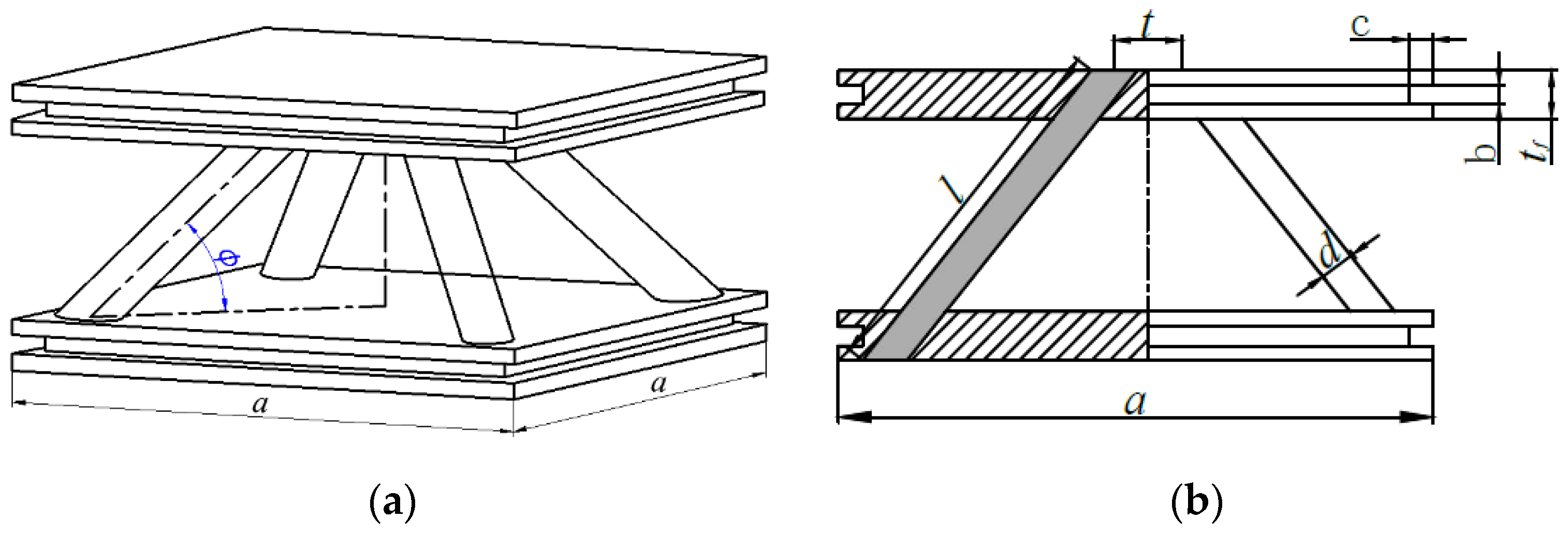
The unit cell schematic diagram of a 2D lattice sandwich structure is shown in Figure 1. The panel with small distance between the rod cores is called the upper panel, and the panel with large distance between the rod cores is called the lower panel.
As shown in Figure 1, is the length of the core. is the diameter of the core. is the length of the panel. is the thickness of the panel. is the groove width of the panel. is the groove height of the panel. is the distance between two neighboring points of the upper panel. is the included angle between the core and the lower panel. The parameters of the unit cell are shown in Table 1.
The relative density of the unit cell is defined as:
where represents the diameter of the core and represents the length of the core [20].
High-quality structural materials should have high specific strength. The higher the specific strength, the lighter the mass of the material used to achieve the corresponding strength. Building structural materials not only need to bear external loads but also need to bear their own weight. Specific strength is an index to measure whether building materials are light and high strength. The specific strength refers to the strength per unit volume and mass, which is equal to the ratio of the strength and apparent density of the material at the fracture point. The specific strength can be defined as:
where represents the specific strength, F represents the externally applied load, and represents the apparent density of lattice structure.
The load mass ratio can be defined as:
where represents the load mass ratio, represents the peak force of the lattice truss core sandwich structures, and represents the mass of the lattice truss core sandwich structures.
2.2. Specimen Structure
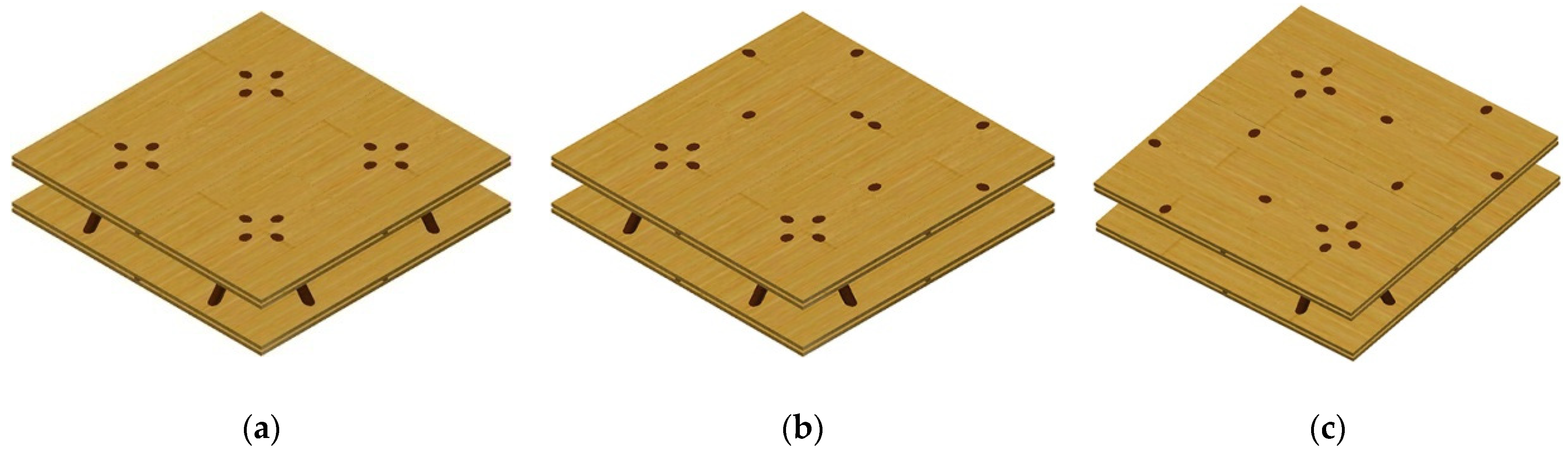
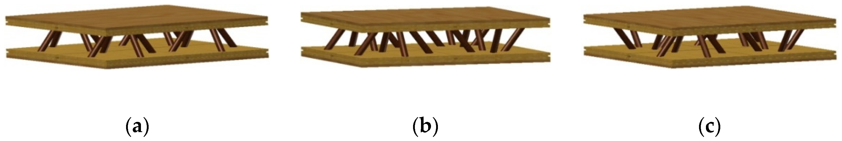
Three types of assembled 2D wood pyramid lattice sandwich structure can be formed by two-dimensional lattice sandwich structure unit cells, as shown in Figure 2.
As can be seen from Figure 2, the unit cell is the core of the structure. The tenon and groove splicing method is used to splice multiple unit cells into different structural forms and large-size specimens. The specimen can form a variety of structural forms, such as grid, hollow slab, beam, column, and so on, which is consistent with the now vigorously developed fabricated wood structure [21,22], and the unit cell size can be changed according to the application requirements to expand its application scope.
3. Experimental Programs
3.1. Mechanical Behaviors of Raw Materials
In the specimen, the panel is larch finger-jointed timber and the core is birch timber. In the specimen, the component material of the cell panel is finger joint material. The side tenon of the cell panel is coated with glue, and the tenon bar is inserted into the slot. The side of the cell panel is also coated with glue, so that the cells can be glued and combined into the specimen. We used 3 mm thick plywood as the tenon bar. On the specimen, the adhesive used is epoxy resin (the quality ratio of epoxy resin and curing agent was 10:6). In the flat compression test, the number of each type of specimen is 5. According to ASTM C365–16, the tests were performed on a universal mechanical testing machine by one-way displacement loading under the following conditions: displacement rate, 0.5 mm/min; home temperature, 20 °C ± 2 °C.
In order to study the mechanical properties of the specimen, the mechanical properties of the constituent materials of the unit cells in the specimen are tested, and the results are shown in Table 2. According to ASTM C365 standard [23], the plane compression test uses a universal mechanical testing machine Model WDW-50, (MTS Systems (China) Corporation, Shenzhen branch, China).
3.2. Fabrication
In the early stage of this paper, a variety of unit cell models were printed by 3D machine, and the effects of core diameter (), angle between core and panel (), and panel thickness () on unit cell compression properties were studied. When d is 10 mm, 12 mm, 16 mm, is 45°, 52°, 60°, and is 10 mm, 12 mm, and 20 mm, respectively; the test results show that when the core diameter is the same as the thickness of the panel and the angle between the core and the panel is 52°, the bearing capacity of the unit cell structure is the largest, and the energy absorption of the unit cell structure is the best. At this time, the failure mode of the unit cell structure is core creep fracture [13]. Therefore, the angle between the core and the panel is 52° in this study.
Larch finger jointed timber is one of the important components of light wood struc- ture [24]. Larch is widely distributed in Northeast China and the Far East of Russia [25], which is a structural timber with excellent mechanical properties [26]. Birch is cold resistant, fast-growing, high mechanical strength, good bonding performance, and is mostly used in the form of plywood [27]. Larch with finger joint was purchased from Dafa Wood Products, Harbin, China. Birch core was purchased from Shuguang farm, Heilongjiang Province. Epoxy resin was obtained from Institute of Petrochemistry Heilongjiang Academy of Sciences, Harbin, China.
The unit cells in the specimen were made by inserting glue. The upper and lower panels were drilled with a bench drill. The cores were inserted into the holes of the panels and bonded with epoxy resin to form the structural unit cell of the specimen. The connection between the unit cells in the specimen adopted the way of tenon and groove splicing, that is, after pouring epoxy resin glue into the groove of the upper and lower panels of the unit cells, the splicing strip was embedded in it, and after the glue was cured, the unit cells were firmly connected to form a multi unit cell specimen. The size of the specimen used in this test is 380 mm × 380 mm × 58 mm, and the number of each type of specimen is 5.
The specimen is placed on the horizontal worktable of the universal mechanical testing machine, and a self-made horizontal pressing plate is placed on the specimen. The size of the pressing plate is 440 mm × 424 mm × 30 mm, and the density is 7.86 g/cm−3. The compression load was applied to the specimen at the loading rate of 1 mm/min for flat compression test.
4. Results and Discussion
4.1. Compression Failure Mode of Specimens
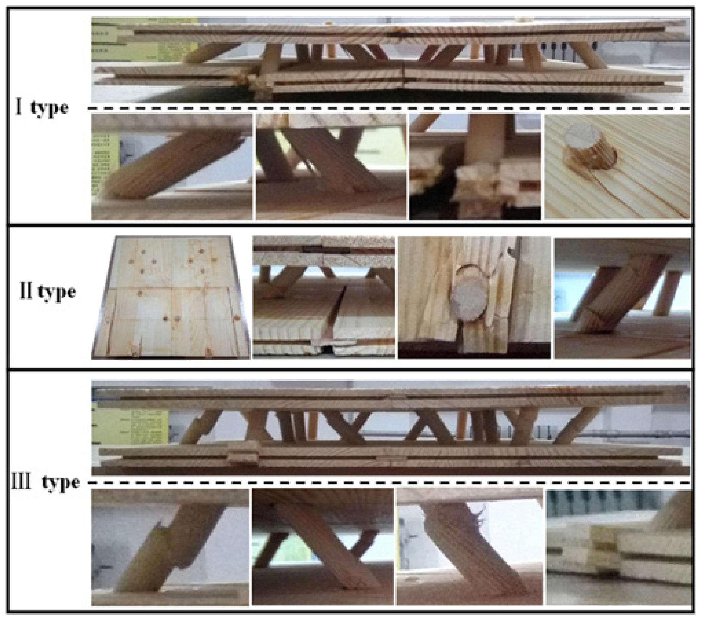
According to ASTM c365–16, the three configuration structures of the prefabricated 2D wood pyramid lattice sandwich structure were tested under flat compression. The failure mode of the structure is shown in Figure 3.
As shown in Figure 3, the failure mode of the type I specimen is that the lower panel bulges at the unit cell junction, the lower panel cracks at the junction of the core and panel, the core breaks at the root, the core splits, and the core is pulled out from the upper panel. The failure mode of type II specimen is that the lower panel is separated at the unit cell junction, the lower panel is cracked at the junction of the core and the panel, the core is pulled out from the upper panel, and the panel around the core is damaged. The broken position of the core is not at the root of the core, but it moves up from the root to the middle part. The failure mode of type III specimen is that the core breaks at the root, deviates from the root, and breaks in the middle part, and the panel is damaged at the joint of core and panel, but the whole specimen is intact.
The common point of the failure of the three types of specimens is that the core breaks at the root and the lower panel cracks at the joint of the core and the panel. The failure of the panel is mainly the crack along the grain of the lower panel. This is due to the volume and boundary effect of the lower panel, which cannot completely limit the deformation of the core, resulting in failure.
4.2. Veneer Reinforcement
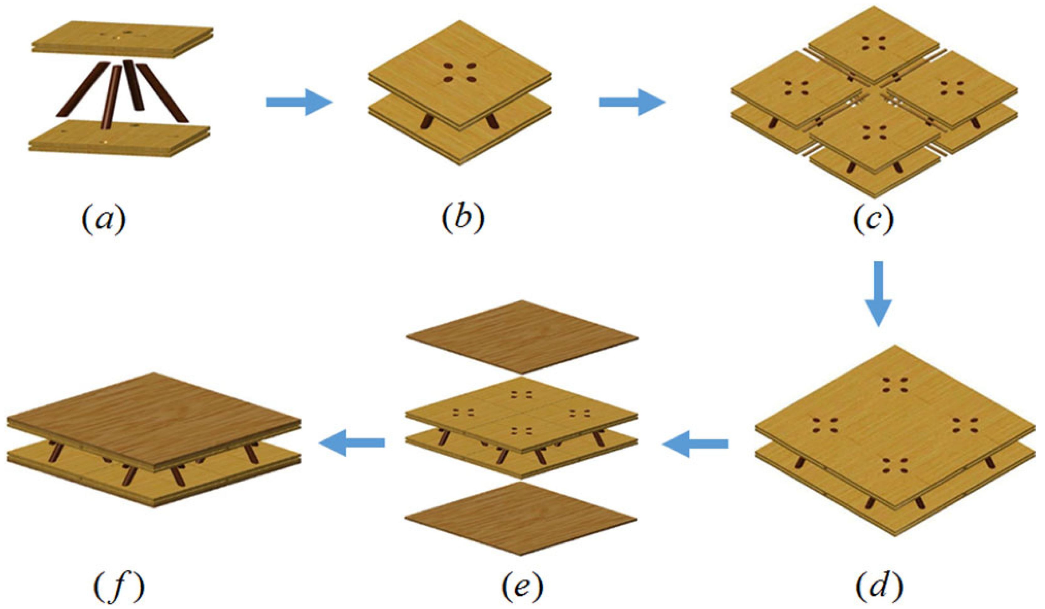
According to the failure modes of type I, type II, and type III specimens, it can be concluded that when the specimen is under load, the panel and the core squeeze each other; the panel not only fixes the core but also transfers the bearing capacity to the core. According to Jin et al. [15] and Wang et al. [16], the mechanical properties of the panel have a significant effect on the compressive strength of the specimen. In order to improve the flat compression strength of the specimen, epoxy resin adhesive was used to glue a 5 mm thick veneer on the upper part of the upper panel and the lower part of the lower panel of the original specimen to reinforce the panel. Birch veneer with a thickness of 5 mm was used, and the veneer size was the same as the specimen size. The reinforced veneer of the specimen is a veneer with the size of 380 mm × 380 mm × 5 mm. The lattice sandwich structure with reinforced veneer is shown in Figure 4.
The reinforced veneer of the specimen is a veneer with the size of 380 mm × 380 mm × 5 mm. When it is glued with the upper and lower panels of the specimen, the texture of the veneers is consistent with that of the upper panel and lower panel. The specimens were cured for 24 h under 0.5 MPa pressure. The upper panel and the lower panel of type I, II, and III specimens in Figure 2 are respectively glued with reinforced veneer, which are numbered R I, R II, and R III, as shown in Figure 5.
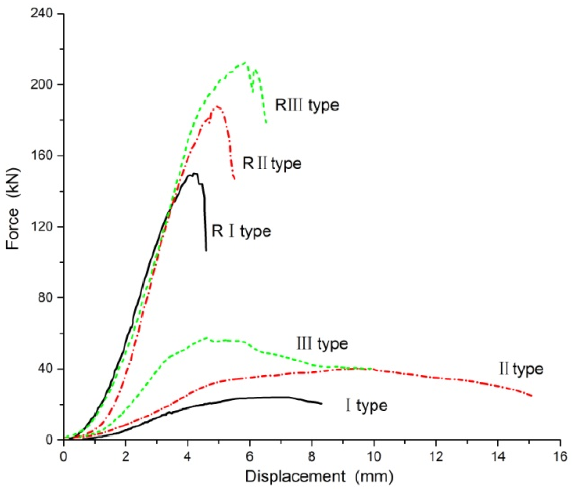
The force–displacement curves of type I, II, III, RI, RII, and RIII specimens are shown in Figure 6. The maximum loads of type I, II, and III specimens are 24.07 kN, 39.48 kN, and 58.24 kN, respectively. The maximum loads of type RI, RII, and RIII specimens are 152.87 kN, 187.48 kN, and 212.14 kN, respectively. The load-carrying capacity of the specimens with veneer reinforcement is 6.35, 4.75, and 3.64 times higher than that of the specimens without veneer reinforcement, respectively. The failure mode of specimens with veneer reinforcement is shown in Figure 7. The failure mode of the specimen is that the reinforced veneers are damaged, the upper and lower panels are cracked, and the cores are broken.
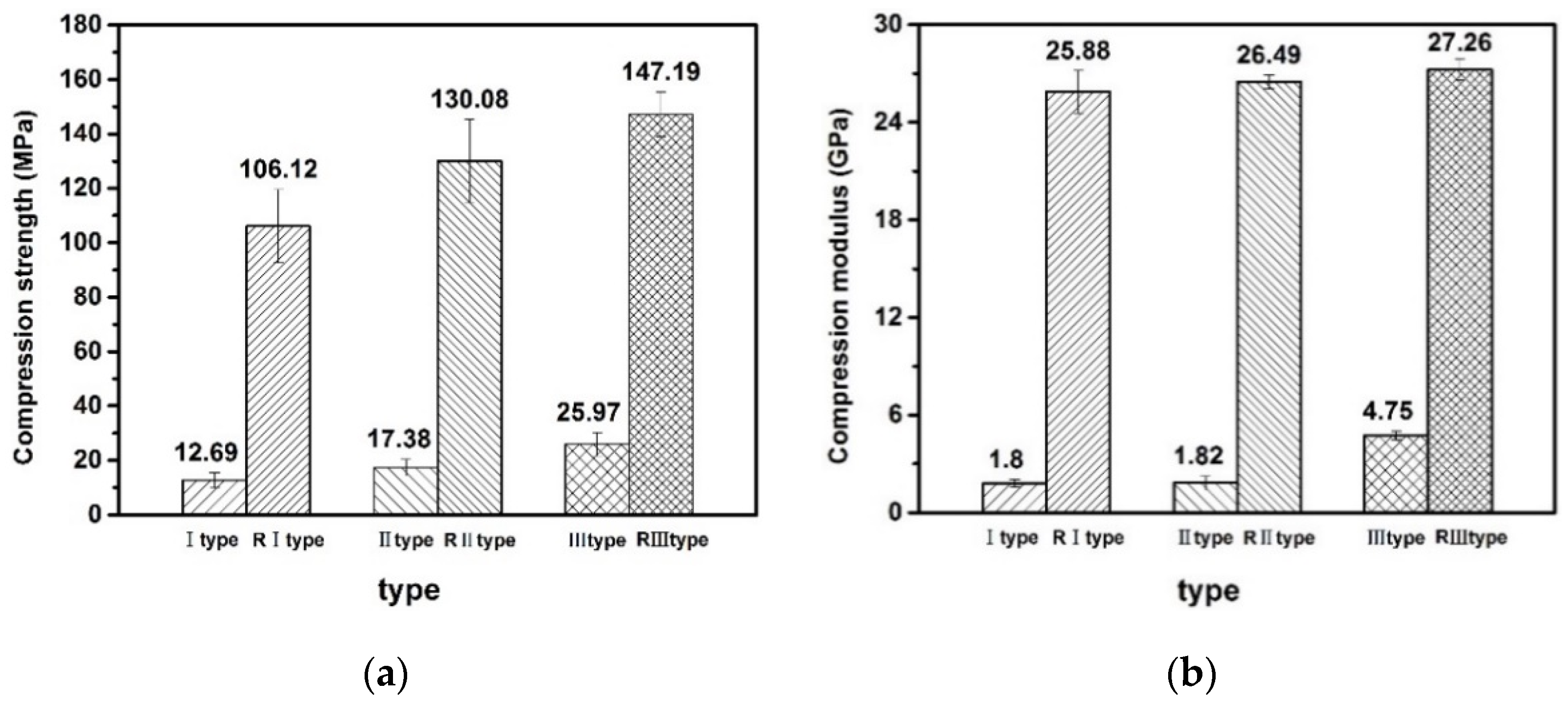
The analysis and comparison of six specimens (numbered I–III, RI–RIII) of the prefabricated 2D wooded pyramid lattice truss core sandwich structure are shown in Figure 8.
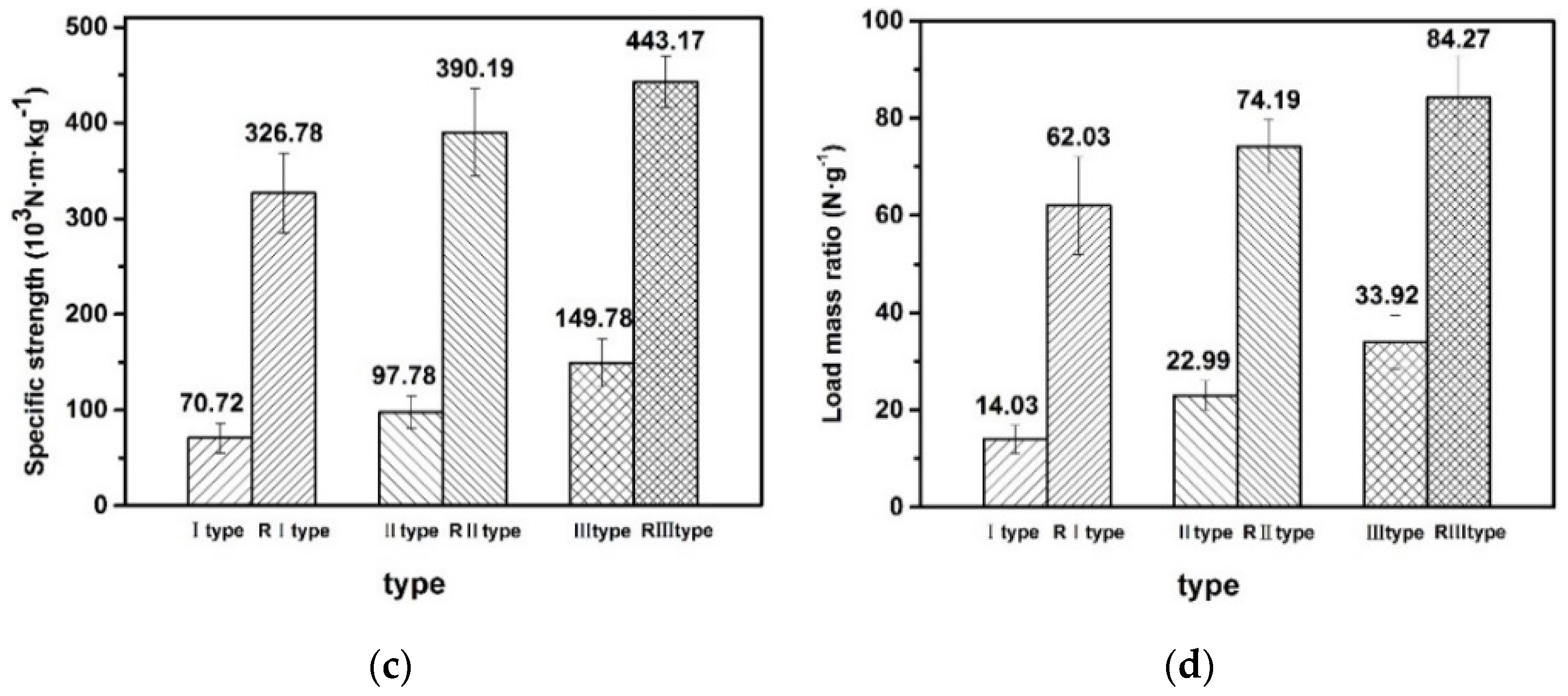
When the bearing area of the specimens is the same, the compressive strength, compressive modulus, specific strength, and load mass of the specimens with reinforced veneer are significantly higher than those of the specimens with unreinforced veneer. Among the reinforced specimens, the value of type RIII is the largest and that of type RI is the smallest. Among the unreinforced specimens, the value of type III specimen is the largest and that of type I specimen is the smallest. Compared with the specimens with unreinforced veneer, the compressive strength of the specimens with reinforced veneer are 5–8 times higher, the compression modulus are 5–14 times higher, the specific strength are 3–5 times higher, and the load mass ratio are 2–5 times higher. For the specimen with veneer reinforcement, it can be concluded that the bearing capacity of the panel and the bonding capacity between the panel and the core are improved; thus, the overall flat compression performance of the specimen is improved. The different arrangement of unit cells in the specimen has a great influence on the flat compression performance of the specimen.
Zheng et al. [12] used WPC, GFRP, OSB, and birch to fabricate a double-X-type lattice sandwich structure with specific strength of 8.22 × 10³∙N∙m∙kg−1, 27.32 × 10³∙N∙m∙kg−1, 27.40 × 10³∙N∙m∙kg−1, 29.90 × 10³∙N∙m∙kg−1, 44.31 × 10³∙N∙m∙kg−1, and 55.83 × 10³∙N∙m∙kg−1. Li et al. [14] used birch core and poplar veneer to prepare wood lattice sandwich structure, whose specific strength were 37.33 × 10³·N·m·kg−1, 54.7 × 10³·N·m·kg−1, and 61.88 × 10³·N·m·kg−1. The load mass ratio of the natural fiber-based isogrid lattice cylinder structure prepared by Hao et al. [18] is 79.323 N/g. The load mass ratio of the glass fiber and carbon fiber grid column structure studied by Zhang et al. [4] is 47.23 N/g and 69.35 N/g, respectively. The specific strength and load mass ratio of the specimens with reinforced veneer in this study are higher than those of these structures. Therefore, the prefabricated wooden pyramidal lattice truss core sandwich structure has better flat compression performance.
4.3. Theoretical Analysis
4.3.1. Stress Analysis of Core
The bearing capacity of the specimen under the flat compression state is determined by the panel, core, the bonding strength between the panel and core, and the bonding strength between the unit cells. The core is the main force of the structure. The premise of the stress analysis of the core in the flat compression state is that the panel and the core are fixed, the panel can limit the displacement of the core, and there is no relative displacement between the panel and the core. Wood is an elastic–plastic material. In order to facilitate mechanical analysis, this paper assumes that the core is linear elastic and isotropic.
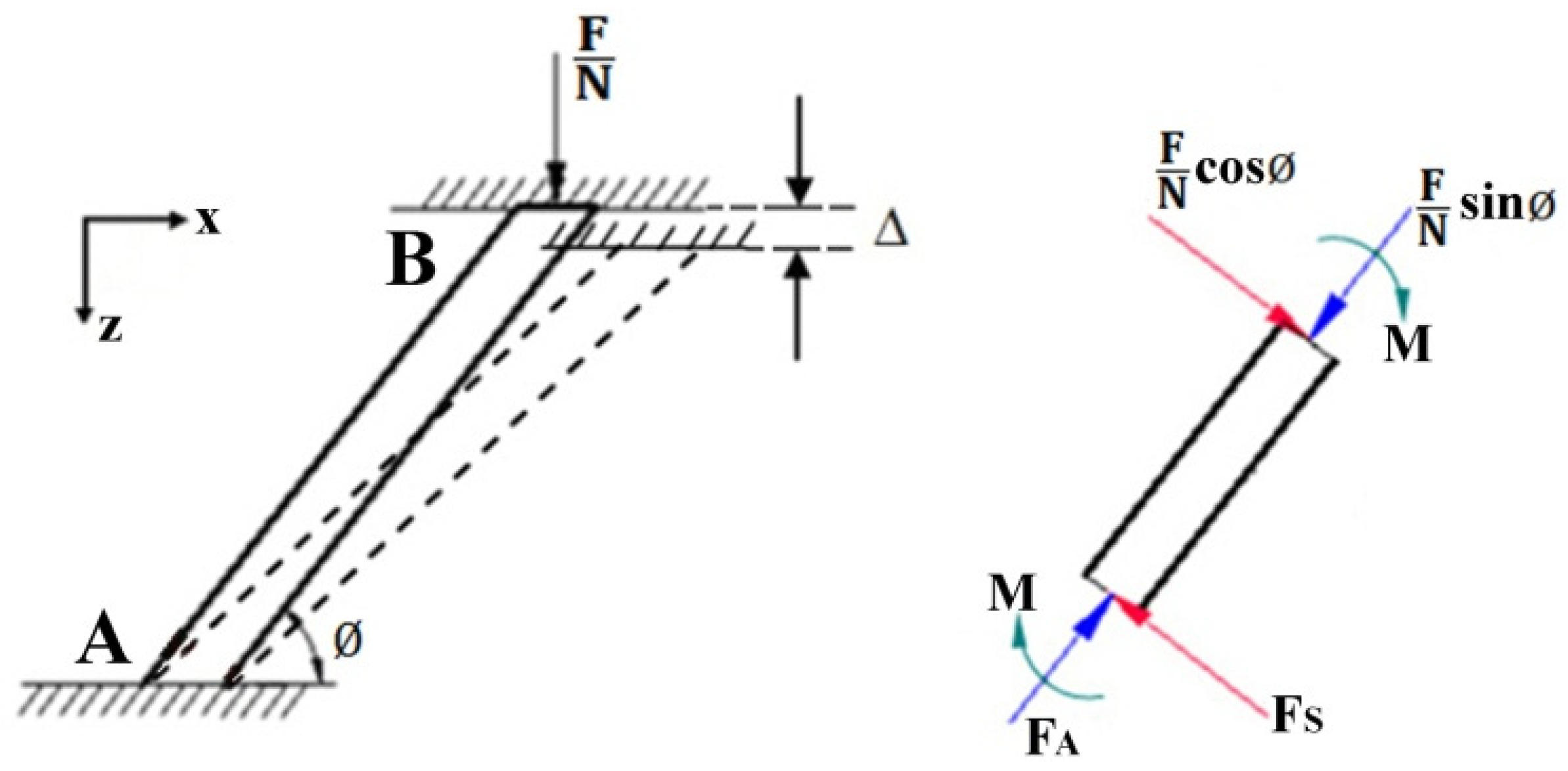
The specimen contains N cores. Under the action of flat pressure load F, the force analysis of a single core is shown in Figure 9.
Assuming that the displacement in the Z direction of the core under the action of the force is Δ and the lateral displacement and rotation angle are both , then the axial force FA and normal shear FS on the core are:
where EC represents the compression modulus of the core, Δ represents the displacement of the core in the Z direction, EMC represents the flexural modulus of the core, and I represents the moment of inertia of the core section.
The resultant force in the Z direction is:
where N represents the number of core.
The stress state of the core is that the compressive stress on the upper end of the core is equal to the tensile stress on the lower end of the core. The axial stress of the core is:
The shear stress of the core is:
where A represents the cross-sectional area of the core.
The bending moment acting on the core is:
where M represents the bending moment.
The maximum stress generated by bending moment is:
Under the action of flat pressure, the stress acting on the core is the sum of axial stress, shear stress, and bending moment. The maximum stress acting on the core is:
The displacement of the structure in case of failure is given by Li et al. [14].
where is the maximum stress of the core.
Substituting Equations (5), (6) and (13) into Equation (7), the carrying capacity of the structure can be obtained:
The deformation of the structure is as follows:
The theoretical calculation results show that the bearing capacity of the specimen is 78.04 kN.
For the specimen with unreinforced veneer, the calculated value (78.04 kN) is higher than the measured value. This is because the theoretical calculation value is obtained under the ideal stress state of the specimen, and the error caused by the actual connection between the core and the panel in the specimen unit cell and the actual connection among the specimen unit cells are not considered, so the theoretical value of the bearing capacity of the specimen is higher than the experimental value.
For the specimen with reinforced veneer, the calculated value (78.04 kN) is lower than the measured value. This is because only the load-bearing capacity of the core is considered in the theoretical calculation, and the load-bearing capacity of the panel and the force between the unit cells are not calculated. Therefore, the theoretical calculation value is less than the experimental measurement value of the specimen with reinforced veneer.
According to the stress analysis of the core, there are dangerous points at both ends and the center of the core, and compression bending and failure will occur under the action of limit load. The panel is fixedly connected with the cores. When the specimen is under the flat compression load, the panel bears the reaction force of the concentrated load from the cores. When the compressive load increases gradually, the failure of the specimen starts from both ends of the core. As the deformation of the specimen continues to increase, the stress around the panel hole gradually increases until the panel fails.
4.3.2. Stress Analysis of Panel
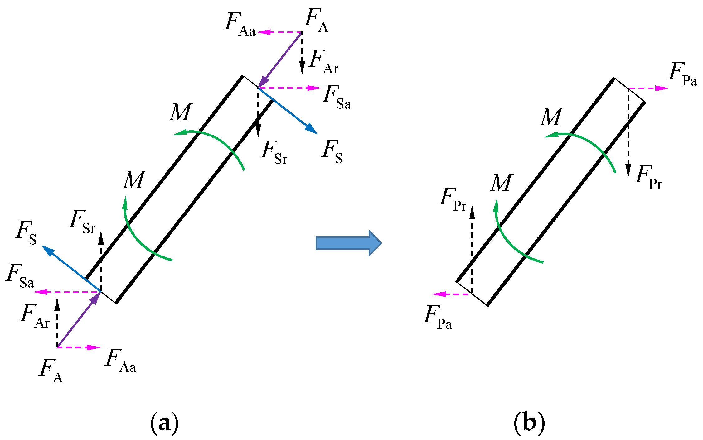
Under the flat compression load, the panel plays a fixed role and makes the force transfer between cores. According to Lifeng et al. [16], the mechanical properties of the panel have a significant effect on the ultimate compressive strength of the specimen. The core is subjected to the combined action of axial force FA, shear force FS, and bending moment M. In Figure 10a, the shear force FS is decomposed into a vertical downward force FSr and a horizontal force FSa parallel to the panel. The axial force FA is decomposed into vertical downward force FAr and horizontal force FAa parallel to the panel. FSr and FAr have the same direction and can be combined into the force FPr acting on the core. FSa and FAa are horizontal forces in opposite directions and parallel to the panel, which can be combined into horizontal forces FPa acting on the panel. Figure 10b shows the bending moment M, force FPr, and horizontal force FPa acting on the core after decomposition.
The stress analysis of type I, II, and III specimens is carried out according to Figure 10. The panel is subjected to the horizontal force FPa acting on the core, and the stress analysis of the panel is shown in Figure 11.
In Figure 11, the forces relationships are shown in Equation (22).
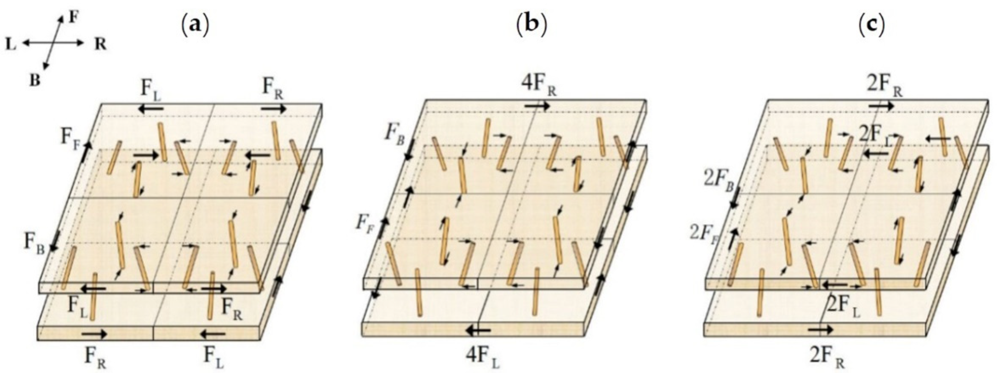
The core position of adjacent unit cells in type I specimen is shown in Figure 11a. Under the action of the flat compression load, the horizontal forces acting on the panel in the LR direction are and , and their values are equal, but the action direction is opposite. In the direction of , the horizontal forces acting on the panel are and , and their values are equal, but the acting direction is opposite. The forces and make the connection position of the upper panel separate and the connection position of the lower panel squeeze. Through force analysis, as shown in Figure 11a, the failure mode of type I specimen is consistent with that of type I specimen in Figure 3. In Figure 3, the connection between the two unit cells in the lower panel of type I specimen bulges due to extrusion, while the upper panel does not change. This is because at the upper panel, the distance between the horizontal forces acting in the opposite direction in the two unit cells is large, and the concentrated force in the opposite direction from the core is less than the cohesive force between the unit cells, so the unit cells in the upper panel are not separated. At the lower panel, the distance between the two opposite horizontal forces in the inner direction of the two unit cells is small, and the concentrated reaction force from the core of the panel is greater than the bonding force of the adjacent two unit cells, resulting in the extrusion of the lower panel unit cells and the uplift of the panel at the unit cell connection.
The core position of adjacent unit cells in type II specimen is shown in Figure 11b. Under the flat compression load, the horizontal forces acting on the panel in the direction of are and , which form equal and opposite forces in the upper and lower panels of the specimen, resulting in the separation or extrusion of the panel at the joint. In the LR direction, the force acting on the upper panel is four times that of , and the force acting on the lower panel is four times that of , which makes the upper and lower panels move in parallel. The results of the comparison between the failure mode of type II specimen in Figure 11b and that of type II specimen in Figure 3 show that under the combined action of the internal force of the specimen panel and the force between the upper and lower panels, the dangerous point of the core of the type II specimen moves upward from the root, and the bearing capacity is higher than that of the type I specimen. In the type III specimen, the core position of adjacent unit cells is shown in Figure 11c. Under the flat compression load, the forces acting on the same panel in the direction are 2 and 2, and the forces between the upper and lower panels are still 2 and 2. The forces acting on the same panel in the LR direction are 2 and 2, and the forces between the upper and lower panels are still 2 and 2. These forces restrict each other. Therefore, the bearing capacity of specimen III is higher. By comparing the failure mode of type III specimen in Figure 11c with that of type III specimen in Figure 3, it can be seen that when the external load increases, the force on the panel increases, and the shear force and bending moment of the core increase, which causes the dangerous point of the core to shift to the middle of the core and makes the core break in the middle, which is the same as the failure of type III specimen in Figure 3 in the same way.
According to the stress analysis of the panel, the bearing capacity of the panel is closely related to the material of the panel. Wood is mainly composed of cellulose, hemicellulose, and lignin. The cellulose molecular chains are aggregated into bundles and exist as ordered microfibrils. In the longitudinal direction, the microfibrils are strongly bonded by C-C and C-O bonds. In the transverse direction, the cellulose chains of microfibrils are bonded by hydrogen bonds (–OH). The energy of this bond is much smaller than that of the longitudinal C-C and C-O bonds of wood cellulose. When the larch finger jointed timber is used as the panel to bear the plane compression load, the load is perpendicular to the panel, and the material is stressed in the transverse direction, which leads to the weak bearing capacity of the panel. Under the combined action of the horizontal force acting on the panel and the pressure perpendicular to the panel, the panel splits along the grain, or the unit cells composed of the specimen are separated. Through theoretical analysis, the failure mode of the specimen is consistent with that of the specimen in Figure 3.
4.4. Finite Element Analysis
Based on Auto Inventor software, finite element analysis is the prediction standard of the deformation process of the wood pyramid lattice sandwich structure under quasi-static compression. The geometric parameters of the finite element analysis model are the same as those of the experimental specimen. The mechanical properties of the model material are shown in Table 2.
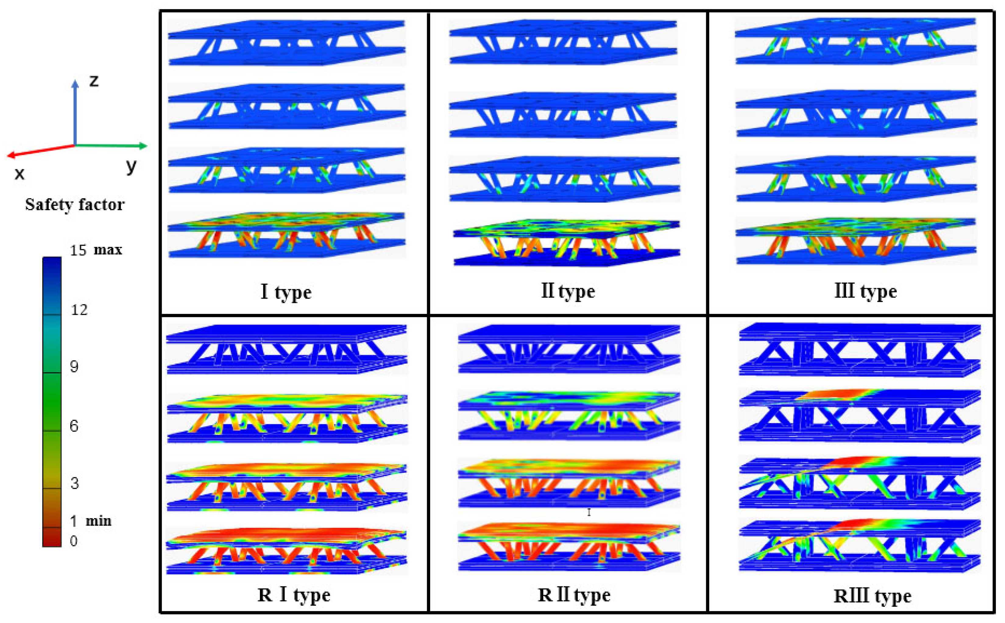
In the simulation process, the material of the upper and lower panels is structural steel; the upper and lower panels of the unit cell are fixed with the fixed plate; the lower panel of the model is fixed horizontally, and the load is applied on the upper panel. Quasi-static compression simulation is difficult to quantitatively describe the elastic–plastic change of wood structure, so this paper can only qualitatively analyze the change state of specimens under flat compression load. C3D4 is selected as the solid unit of the model. In the model, a glued connection is selected between the panel and the core, a separated but no sliding connection is selected between the model and the upper and lower fixed plates, and a glued connection is selected between the unit cell and the splicing strip. Based on the ultimate stress (50.28 MPa) of the core, the bearing capacity of six types of specimens (I–III, RI–RIII) is analyzed. It is concluded that the bearing capacity of the type RIII specimen is the largest and that of the type I specimen is the smallest. In the structural design of building engineering, the safety factor is usually used to reflect the safety degree of the structure. Therefore, the failure state and failure order of the structure can be judged from the safety factor. The distribution of the safety factors of the six specimens is shown in Figure 12. In the simulation results, the failure of type I, type II, and type III structures first occurs at the root of the core. With the increase of the load, the stress of the core gradually increases and transfers to the panel contacting with the core. With the increase of the external load, the stress on the panel diffuses around until the panel fails. In the simulation results, the failure of RI, RII, and RIII structures is that the stress of the core and the panel is generated at the same time and gradually increases with the increase of the external load. The stress of the core first occurs at the root and then gradually moves up, and the stress of the panel gradually expands from the contact position between the core and the panel to the whole panel. The stress of the RIII simulation structure first appears at the root of core and the joint of two panels and then expands with the increase of external load until failure.
4.5. Performance Analysis
Six types of specimens (I–III, RI–RIII) were tested on the mechanical properties of flat pressure. Through the analysis and comparison of load, displacement, and failure mode, it shows that the bearing capacity of the type III specimen is the strongest among the specimens with unreinforced veneer, and that of the type RIII specimen is the strongest among the specimens with reinforced veneer. The bearing capacity of the type RIII specimen is 3.64 times that of the type III specimen. Therefore, the bearing capacity and structural strength of the type RIII specimen are the largest. By analyzing and comparing the compression strength, compression modulus, specific strength, and load mass ratio of six types of specimens, it is concluded that the compression performance of the type III specimen is the best among the specimens with unreinforced veneer, and that of the type RIII specimen is the best among specimens with reinforced veneer. The compressive property of the type RIII specimen is 2.5, which is six times higher than that of the type III specimen. The results show that the type RIII type specimen has the best energy absorption performance and bearing capacity. Therefore, the structural form of the type RIII specimen is used in the structural design of seismic materials.
The quasi-static compression properties of the specimens were analyzed by finite element method. Since the wooden material is anisotropic, it can simulate the load-bearing capacity of the specimen, but it cannot accurately describe the elastic–plastic properties of the wooden material. Therefore, the simulation model uses the qualitative analysis method to obtain the bearing capacity of six types of specimens (I–III, RI–RIII). The simulation results show that the bearing capacity, structural safety factor, and failure mode of the six types of specimens (I–III, RI–RIII) are consistent with the failure state of the experimental test.
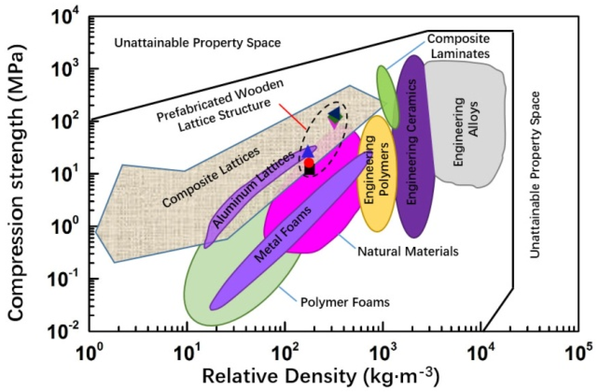
Wooden materials are low-density and high-strength materials. The apparent density of the six specimens is lower than that of the constituent materials. In the density–strength diagram [28] of the material shown in Figure 13, all the six specimens (I–III, RI–RIII) belong to the low-density zone and the flat compressive strength is high. The strength values of the six specimens (I–III, RI–RIII) ranged from 12.69 to 147.19 MPa, belonging to high-strength materials in the natural material region and also in the lattice structure region of composite materials. The flat compressive strength of type RI–RIII specimens is higher than that of the structural materials itself.
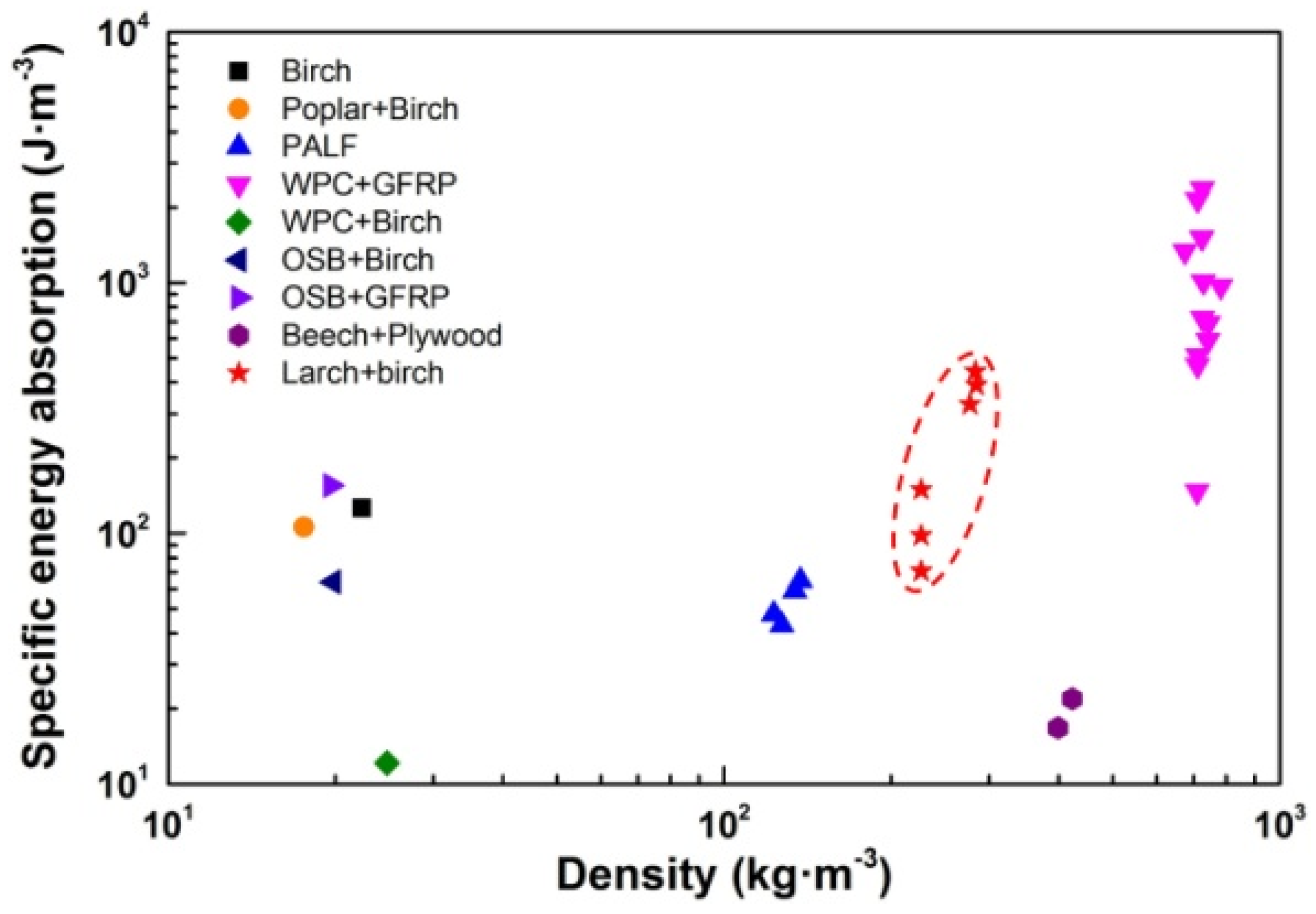
The specific energy absorption of the wooden lattice sandwich structure is shown in Figure 14. In Figure 14, Birch sawn timber, Poplar LVL panels [17], PALF [19], WPC, GFRP, OSB, Birch [20], Beech, Plywood, and Larch are the materials of the wooden lattice structure. The wooden lattice structure is composed of one or two materials. The specimens studied in this paper are composed of larch and birch materials. Its specific energy absorption ranges from 70.72 to 443.17 J/m3. The specific energy value of the specimen is lower than that of the lattice structure composed of WPC and GFRP, but the structural density of the specimen is much lower than that of the lattice structure composed of WPC and GFRP.
According to the above analysis, the six types of specimens (I–III, RI–RIII) all have high bearing capacity. When the external load acts on the vertical direction and displaces, the bearing capacity of the six specimens is quite different. This is because on the one hand, the arrangement of unit cells in the specimens is not exactly the same; on the other hand, three specimens have reinforced veneers, while the other three specimens have no reinforced veneers. In the six types of specimen structure, the core plays a major role in bearing the external load. The arrangement of the unit cells in the specimen affects the bearing capacity of the specimen. The strengthened panel increases the bonding area between the panel and the core, and the connection among the unit cells enhances the bearing capacity of the specimen.
The specimen in this study has a large size, which can be more easily applied to building structural components. The structure size can also be adjusted according to the building structure and application site. If the digital wood processing technology is used in the fabricated wooden pyramid lattice sandwich structure, it can not only reduce the error of wood-based materials in the processing process to the greatest extent but also carry out customized processing, forming a light wooden structure construction combining digital innovation and art design. At the same time, the topology of the core layer and the reinforcement of the panel material will be the research direction in the future.
5. Conclusions
Through the method of inserting glue, the panel and the cores are composed of structural unit cells, and the fabricated 2D wooden pyramid lattice sandwich structure specimen is formed by the method of mortise and groove splicing between the unit cells, and the static flat compression test is carried out. The conclusions are as follows:
- The flat compression test shows that the arrangement of unit cells in the specimen affects the bearing capacity of the specimen. The load-carrying capacity of type III specimen is 2.4 times that of type I specimen. The load-carrying capacity of the specimens with veneer reinforcement is 6.35 times, 4.75 times, and 3.64 times higher than that of the specimens with unreinforced veneer. Compared with the unreinforced specimens, the specific strength and the load mass ratio are increased by 3–5 times and 2–5 times, respectively.
- The main failure modes of the specimens are core fracture and panel cracking. With the increase of the bearing capacity of the structure, the fracture mode of the core gradually moves upward from the root fracture and splitting of the core to the middle of the core, which is a shear fracture perpendicular to the axial direction. The results of compression performance, failure order and form obtained by finite element analysis are consistent with the experimental results. The failure of the specimen with unreinforced veneer starts from the root of the core, while the failure of specimen with reinforced veneer starts from the root of the core and the panel at the same time.
- The maximum load mass ratio of the structure with reinforced veneer is larger than that of the same type of wooden lattice sandwich structure, which proves that the structure with reinforced veneer is very significant to improve the flat compression performance of the structure.
Author Contributions
Conceptualization, D.Y. and C.F.; methodology, D.Y. and C.F.; software, D.Y. and C.F.; validation, D.Y. and C.F.; formal analysis, D.Y.; investigation, D.Y.; resources, Y.H.; data curation, D.Y.; writing—original draft preparation, D.Y. and C.F.; writing—review and editing, C.F.; supervision, Y.H.; project administration, Y.H.; funding acquisition, Y.H. All authors have read and agreed to the published version of the manuscript.
Funding
This research was funded by the Postdoctoral Science Foundation of China, grant number 2017M611339, the Fundamental Research Funds for the Central Universities, grant number 2572020DR13, the National Natural Science Foundation of China, grant number 31470581 and the Natural Science Foundation of Heilongjiang Province, grant number LH2020F010.
Data Availability Statement
The data presented in this study are available on request from the corresponding author.
Conflicts of Interest
The authors declare no conflict of interest.
References
- Yang, J.-S.; Ma, L.; Schmidt, R.; Qi, G.; Schröder, K.-U.; Xiong, J.; Wu, L.-Z. Hybrid lightweight composite pyramidal truss sandwich panels with high damping and stiffness efficiency. Compos. Struct. 2016, 148, 85–96. [Google Scholar] [CrossRef] [Green Version]
- Jiang, W.; Yang, B.; Guan, X.; Luo, Y. Bending and twisting springback prediction in the punching of the core for a lattice truss sandwich structure. Acta Metall. Sin. 2013, 26, 241–246. [Google Scholar] [CrossRef]
- Schaedler, T.A.; Chan, L.J.; Clough, E.C.; Stilke, M.A.; Hundley, J.M.; Masur, L.J. Nanocrystalline Aluminum Truss Cores for Lightweight Sandwich Structures. JOM 2017, 69, 2626–2634. [Google Scholar] [CrossRef] [Green Version]
- Zhang, G.; Wang, B.; Ma, L.; Xiong, J.; Yang, J.; Wu, L. The residual compressive strength of impact damaged sandwich structures with pyramidal truss cores. Compos. Struct. 2013, 105, 188–198. [Google Scholar] [CrossRef]
- Mohammadi, M.S.; Nairn, J.A. Crack propagation and fracture toughness of solid balsa used for cores of sandwich composites. J. Sandw. Struct. Mater. 2014, 16, 22–41. [Google Scholar] [CrossRef]
- Dimitrov, N.; Berggreen, C. Probabilistic fatigue life of balsa cored sandwich composites subjected to transverse shear. J. Sandw. Struct. Mater. 2015, 17, 562–577. [Google Scholar] [CrossRef]
- Brandner, R.; Dietsch, P.; Dröscher, J.; Schulte-Wrede, M.; Kreuzinger, H.; Sieder, M. Cross laminated timber (CLT) diaphragms under shear: Test configuration, properties and design. Constr. Build. Mater. 2017, 147, 312–327. [Google Scholar] [CrossRef]
- Dahy, H. Biocomposite materials based on annual natural fibres and biopolymers-Design, fabrication and customized applications in architecture. Constr. Build. Mater. 2017, 147, 212–220. [Google Scholar] [CrossRef]
- Qu, M.; Pelkonen, P.; Tahvanainen, L.; Arevalo, J.; Gritten, D. Experts’ assessment of the development of wood framed houses in China. J. Clean. Prod. 2012, 31, 100–105. [Google Scholar] [CrossRef]
- Rutkevičius, M.; Munusami, S.K.; Watson, Z.; Field, A.D.; Salt, M.; Stoyanov, S.D.; Petkovc, J.; Mehla, G.H.; Paunova, V.N. Fabrication of novel lightweight composites by a hydrogeltemplating technique. Mater. Res. Bull. 2012, 47, 980–986. [Google Scholar] [CrossRef]
- Qin, J.; Zheng, T.; Li, S.; Cheng, Y.; Xu, Q.; Ye, G.; Hu, Y. Core configuration and panel reinforcement affect compression properties of wood- based 2-D straight column lattice truss sandwich structure. Eur. J. Wood Wood Prod. 2019, 77, 539–546. [Google Scholar] [CrossRef]
- Zheng, T.; Yan, H.; Li, S.; Cheng, Y.; Zou, L.; Hu, Y. Compressive behavior and failure modes of the wood based double X type lattice sandwich structure. J. Build. 2020, 30, 1–10. [Google Scholar] [CrossRef]
- Yang, D.; Hu, Y.; Fan, C. Compression Behaviors of Wood Based Lattice Sandwich Structures. BioResources 2018, 13, 6577–6890. [Google Scholar]
- Li, S.; Hu, Y. Optimization of Connection Method of Wood based Lattice Sandwich Structure. J. Northwest For. Univ. 2019, 34, 225–230. [Google Scholar]
- Jin, M.; Hu, Y.; Wang, B. Compressive and bending behaviors of wood based two dimensional lattice truss core sandwich structures. Compos. Struct. 2015, 124, 337–344. [Google Scholar] [CrossRef]
- Wang, L.; Hu, Y.; Zhang, X.; Li, S.; Li, S.; Zhang, H. Design and compressive behavior of a wood based pyramidal lattice core sandwich structure. Eur. J. Wood Wood Prod. 2020, 78, 123–134. [Google Scholar] [CrossRef]
- Klímek, P.; Wimmer, R.; Brabec, M.; Sebera, V. Novel Sandwich Panel with Interlocking Plywood Kagome Lattice Core and Grooved Particleboard Facings. BioResources 2016, 11, 195–208. [Google Scholar] [CrossRef] [Green Version]
- Hao, M.; Hu, Y.; Wang, B.; Liu, S. Mechanical behavior of natural fiber-based isogrid lattice cylinder. Compos. Struct. 2017, 176, 117–123. [Google Scholar] [CrossRef]
- Li, S.; Qin, J.; Li, C.; Feng, Y.; Zhao, X.; Hu, Y. Optimization and compressive behavior of composite 2-D lattice structure. Mech. Adv. Mater. Struct. 2018, 27, 1213–1222. [Google Scholar] [CrossRef]
- Li, X. The Variant Design of Furniture Based Modules with 32mm System through Group Technology Optimization. Packag. Eng. 2015, 36, 55–59. [Google Scholar]
- Jaksch, S.; Franke, A.; Österreicher, D.; Treberspurg, M. A Systematic Approach to Sustainable Urban Densification using prefabricated timber based attic extension modules. Energy Procedia 2016, 96, 638–649. [Google Scholar] [CrossRef] [Green Version]
- Li, J.; Wang, Q.; LYU, S.; Frank, L.; Zhang, T. Relations Between Construction Process of Modern Timber Buildings and Prefabrication Design A Case Study of Canadian Construction Technology. Archit. J. 2018, 6, 106–111. [Google Scholar]
- ASTM C365-16. Standard Test Method for Flatwise Compressive Properties of Sandwich Cores; ASTM International: West Conshohocken, PA, USA, 2016. [Google Scholar]
- Lou, W.L.; Ren, H.Q.; Jiang, J.H.; Wang, Z.H.; Zhou, H.B.; Zhao, X.; Guo, W. Effects of Major Defects on Dimensional Larch Lumber Visual Grading. China Wood Ind. 2010, 2, 1–4. [Google Scholar]
- Jiang, J.H.; Lu, J.X.; Ren, H.Q. Study on Characteristic Values for Strength Properties of Chinese Larch Dimension Lumber. J. Build. Mater. 2012, 15, 361–365. [Google Scholar]
- Zhou, Z.; Bi, K.; Zhang, X. Effects of Cross Section Loading Mode and Finger Joint Type on the Bending Property of Larch Structural Finger Jointed Lumber in Large Dimension. Sci. Silvae Sinicae. 2016, 52, 82–89. [Google Scholar]
- Haiqing, R.; Wei, G.; Yafang, Y. Machine Grading of Lumber in North America. World For. Res. 2006, 19, 66–70. [Google Scholar]
- Wu, L.Z.; Xiong, J.; Ma, L.; Wang, B.; Zhang, G.; Yang, J. Processes in the study on novel composite sandwich panels with lattice truss cores. Adv. Mech. 2012, 42, 41–67. [Google Scholar]
Figure 1.
Unit cell of a pyramidal lattice structure. (a) Axonometric drawing; (b) Side elevation.

Figure 2.
Configuration of prefabricated 2D wooden pyramidal lattice truss core sandwich structures. (a) I type specimen. (b) II type specimen. (c) III type specimen.
Figure 2.
Configuration of prefabricated 2D wooden pyramidal lattice truss core sandwich structures. (a) I type specimen. (b) II type specimen. (c) III type specimen.

Figure 3.
Failure modes of three specimens.

Figure 4.
Lattice sandwich structure with reinforced veneer. (a) Drilling hole. (b) Adhesive bonding. (c) The mortise and tenon splicing method. (d) Prefabricated 2D wooden pyramidal lattice truss core sandwich structures. (e) Reinforced veneer. (f) Reinforced lattice 2D wooden pyramidal lattice truss core sandwich structures.

Figure 5.
Lattice sandwich structure with reinforced veneer of type RI, RII, and RIII. (a) RI type specimen. (b) RII type specimen. (c) RIII type specimen.
Figure 5.
Lattice sandwich structure with reinforced veneer of type RI, RII, and RIII. (a) RI type specimen. (b) RII type specimen. (c) RIII type specimen.

Figure 6.
Force–displacement curve of a wood lattice sandwich structure specimen.

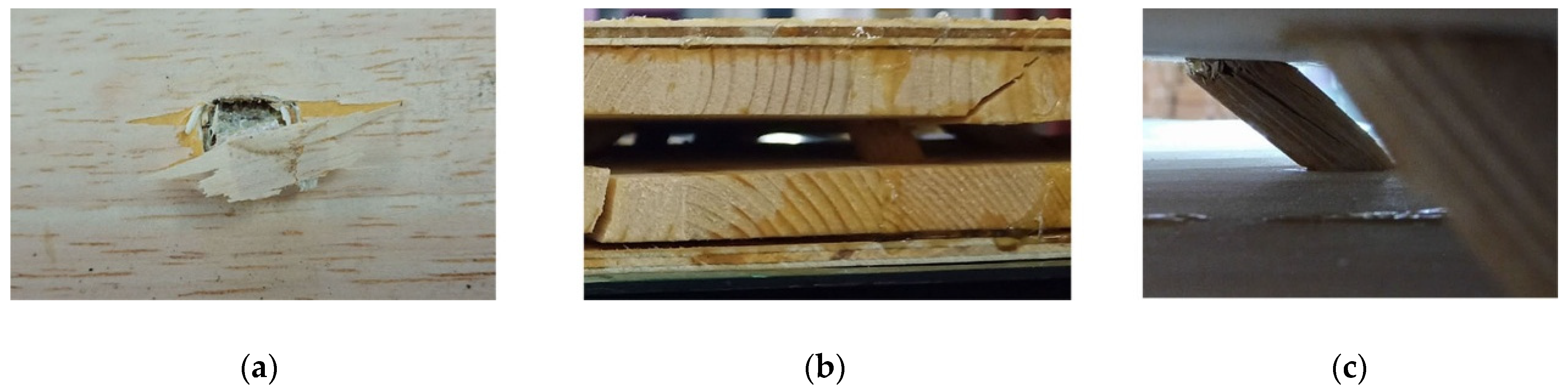
Figure 7.
Failure modes of specimens with veneer reinforcement. (a) Failure of reinforced veneer. (b) Cracking of upper and lower panels. (c) Broken core.
Figure 7.
Failure modes of specimens with veneer reinforcement. (a) Failure of reinforced veneer. (b) Cracking of upper and lower panels. (c) Broken core.

Figure 8.
The analysis and comparison of six specimens of the prefabricated 2D wooden pyramidal lattice truss core sandwich structure: (a) compression strength, (b) compression modulus, (c) specific strength, and (d) load mass ratio.
Figure 8.
The analysis and comparison of six specimens of the prefabricated 2D wooden pyramidal lattice truss core sandwich structure: (a) compression strength, (b) compression modulus, (c) specific strength, and (d) load mass ratio.


Figure 9.
Force analysis of a single core.

Figure 10.
Decomposition of the force acting on the core. (a) Before decomposition. (b) After decomposition.
Figure 10.
Decomposition of the force acting on the core. (a) Before decomposition. (b) After decomposition.

Figure 11.
Force analysis of panels. (a) I type specimen. (b) II type specimen. (c) III type specimen.
Figure 11.
Force analysis of panels. (a) I type specimen. (b) II type specimen. (c) III type specimen.

Figure 12.
Safety factor distribution of the simulation structure.

Figure 13.
Relationship between compressive strength and density of materials [27].
Figure 13.
Relationship between compressive strength and density of materials [27].

Figure 14.
Specific energy absorption of wooden lattice structure.


Table 1.
Geometric parameters of the unit cell.
| Name | (mm) | (mm) | (mm) | (mm) | (mm) | (mm) | (°) |
|---|---|---|---|---|---|---|---|
| value | 180 | 3 | 12 | 12 | 3 | 46 | 52° |
Table 2.
Mechanical behavior of raw materials.
| Material | Moisture Content | (kg/m3) | MOE (GPa) Compressive Flexural | MOR (MPa) Compressive Flexural | ||
|---|---|---|---|---|---|---|
| Larch finger-jointed lumber | 6.94% | 512.41 | 26.68 | 3.69 | 50.30 | 78.86 |
| Birch rod cores | 5.99% | 580.554 | 51.47 | 0.69 | 50.28 | 54.76 |
Publisher’s Note: MDPI stays neutral with regard to jurisdictional claims in published maps and institutional affiliations. |
© 2021 by the authors. Licensee MDPI, Basel, Switzerland. This article is an open access article distributed under the terms and conditions of the Creative Commons Attribution (CC BY) license (https://creativecommons.org/licenses/by/4.0/).
Share and Cite
MDPI and ACS Style
Yang, D.; Fan, C.; Hu, Y. Optimization and Mechanical Properties of Fabricated 2D Wood Pyramid Lattice Sandwich Structure. Forests 2021, 12, 607. https://0-doi-org.brum.beds.ac.uk/10.3390/f12050607
AMA Style
Yang D, Fan C, Hu Y. Optimization and Mechanical Properties of Fabricated 2D Wood Pyramid Lattice Sandwich Structure. Forests. 2021; 12(5):607. https://0-doi-org.brum.beds.ac.uk/10.3390/f12050607
Chicago/Turabian StyleYang, Dongxia, Changsheng Fan, and Yingcheng Hu. 2021. "Optimization and Mechanical Properties of Fabricated 2D Wood Pyramid Lattice Sandwich Structure" Forests 12, no. 5: 607. https://0-doi-org.brum.beds.ac.uk/10.3390/f12050607
Note that from the first issue of 2016, this journal uses article numbers instead of page numbers. See further details here.