
Permanent Magnet Machines for High-Speed Applications

 ,
,
Abstract
:1. Introduction
2. Single-Phase and Three-Phase PM Machines
2.1. Single-Phase
2.2. Three-Phase
2.3. Summary
3. Stator Structures and Winding Configurations
3.1. Stator Structure
3.1.1. Slotted
6-slot/4-pole
6-slot/2-pole
3-slot/2-pole
Optimal Design of Slotted Machines
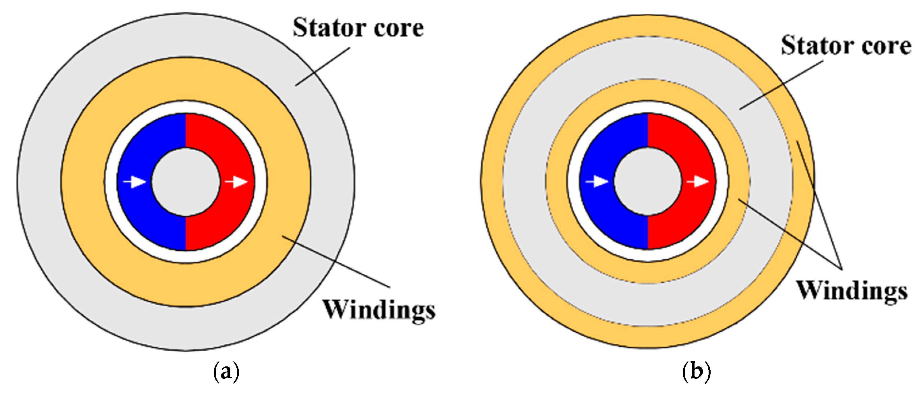
3.1.2. Slotless
3.1.3. Summary of Stator Structures
3.2. Winding Configuration
3.2.1. Overlapping Winding
Slotted Machine
Slotless Machine
3.2.2. Non-Overlapping Winding
Slotted Machine
Slotless Machine
3.2.3. Summary of Winding Configurations
- For high-power multi-slot HSPM machines, overlapping winding and toroidal non-overlapping winding are employed. The main difference between two winding configurations is the end-winding axial length;
- For low-power minimal-slot HSPM machines, the concentrated non-overlapping winding is a dominant winding configuration due to short end-winding axial length. Although it has a short end-winding axial length, the toroidal winding needs additional volume radially for the outside windings. These also produce eddy current losses in the frame.
- For slotless HSPM machines, both overlapping and non-overlapping windings are employed. Full-pitched overlapping windings with the largest winding factor can offer the maximum output torque; however, they have the longest end-winding axial length, while the short-pitched overlapping winding with a relatively small winding factor not only decreases the rotor losses but also improves the rotor mechanical stiffness.
- The toroidal non-overlapping winding with short end-winding axial length and the simple winding process is popular for slotless stator applications.
- The skewed slotless winding, i.e., helical, rhombic, and diamond windings, with compact structure, self-support construction, and no end-winding, is an attractive solution for slotless HSPM machines. However, the non-idealized skewed current direction leads to undesirable torque and force. In addition, the skewed slotless winding needs a 3D model to analyse and requires a special manufacturing process.
4. Rotor Structure
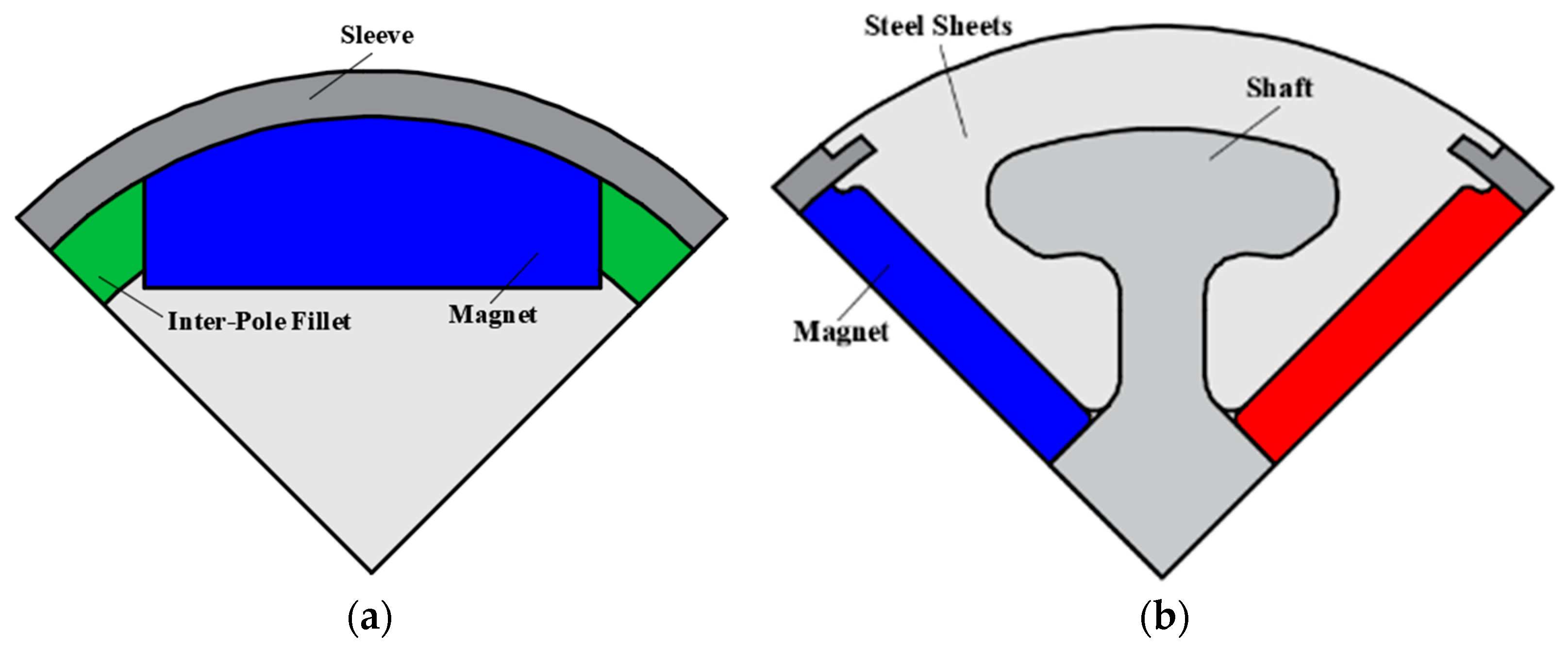
4.1. IPM
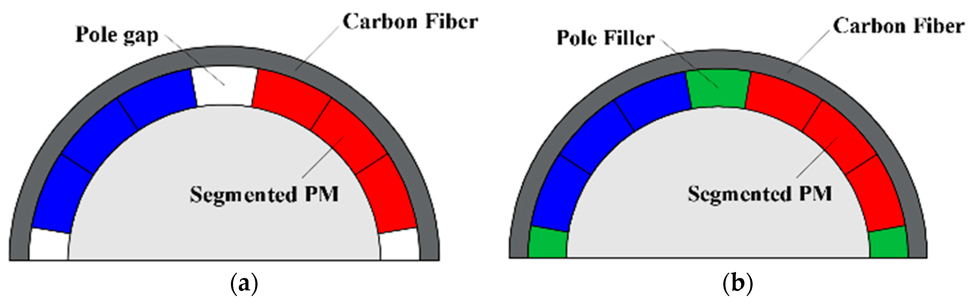
4.2. SPM
4.2.1. Sleeve Design
4.2.2. Pole Arc to Pole Pitch
4.3. Solid PM
4.3.1. Solid PM with Sleeve
4.3.2. Solid PM with Hollow Shaft
4.4. Summary
5. Parasitic Effect
5.1. Stator Iron Loss
5.2. AC Copper Loss
5.3. Rotor Eddy Current Loss
5.4. Windage Loss
5.5. Rotor Dynamic and Vibration
5.6. Thermal Aspect
6. Conclusions
Author Contributions
Funding
Conflicts of Interest
Appendix A

| Reference | Power (kW) | Speed (krpm) | Slot/Pole | Winding | Rotor | Application |
|---|---|---|---|---|---|---|
| [30] | 2000 | 20 | 48s/8p | Overlapping (Full-pitched) | SPM | - |
| [120] | 1120 | 18 | 27s/4p | Overlapping (Full-pitched) | SPM | Pump Drive |
| [46] | 1120 | 18 | 27s/4p | Overlapping (Full-pitched) | SPM | Compressor |
| [146] | 800 | 2.5 | 24s/4p | Overlapping (Full-pitched) | SPM | Prototype |
| [48] | 400 | 10 | 48s/4p | Overlapping (Full-pitched) | SPM | Prototype |
| [147] | 300 | 13.3 | 12s/14p | Concentrated | IPM | Aircraft Gas Turbine |
| [119] | 200 | 40 | 24s/2p | Overlapping (Full-pitched) | SPM | - |
| [148] | 150 | 24 | 24s/2p | Toroidal | Solid PM | Turbo Blowers |
| [32] | 150 | 17 | 36s/4p | Overlapping (Full-pitched) | SPM | Prototype |
| [84] | 140 | 24 | 24s/4p | Overlapping (Full-pitched) | SPM/Spoke-IPM | - |
| [149] | 124 | 36 | 24s/2p | Overlapping (Full-pitched) | SPM | Generator |
| [114] | 117 | 60 | 36s/2p | Toroidal | SPM | Micro Gas Turbine |
| [34] | 117 | 60 | 36s/2p | Toroidal | Solid PM | Prototype |
| [28] | 100 | 500 | Slotless/2p | Toroidal | Solid PM | Mesoscale Gas Turbines |
| [33] | 100 | 50 | 36s/4p | Overlapping (Full-pitched) | SPM | Turbo Generator |
| [85] | 100 | 32 | 24s/4p | Overlapping (Full-pitched) | SPM | Centrifugal Air Blower |
| [150] | 82 | 12.5 | 24s/2p | Overlapping (Full-pitched) | SPM | Centrifugal Pump |
| [35] | 75 | 36 | 24s/2p | Toroidal | Solid PM | Prototype |
| [123] | 57 | 30 | 6s/4p | Concentrated | SPM/Inset-PM | Pumps, Compressors, Blower |
| [110] | 50 | 100 | Slotless/2p | Concentrated/Toroidal/Skewed | Solid PM | - |
| [42] | 50 | 70 | 12s/2p | Overlapping (Full-pitched) | SPM | Centrifugal Turbo-Compressors |
| [87] | 40 | 40 | 36s/4p | Overlapping (Full-pitched) | SPM | Prototype |
| [115] | 40 | 30 | 18s/2p | Overlapping (Full-pitched) | SPM | Light Duty Electric Vehicle |
| [38] | 30 | 96 | 18s/2p | Overlapping (Full-pitched) | SPM | Prototype |
| [88] | 30 | 20 | 36s/6p | Overlapping (5/6 short-pitched) | IPM | Compressor |
| [39] | 25 | 30 | 18s/2p | Overlapping (Full-pitched) | SPM | Prototype |
| [121] | 22 | 120 | 6s/2p | Concentrated | SPM | Prototype |
| [40] | 20 | 26 | 18s/2p | Overlapping (Full-pitched) | SPM | Electric Vehicle |
| [125] | 15.7 | 125 | 12s/2p | Overlapping (Full-pitched) | IPM | Prototypes |
| [63] | 15 | 150 | 6s/2p | Concentrated | SPM | EAT |
| [63] | 15 | 150 | Slotless/2p | Toroidal | SPM | EAT |
| [43] | 15 | 120 | 12S/2P | Overlapping (5/6 short-pitched) | Solid PM | Air Blower |
| [36] | 15 | 30 | 24s/2p | Toroidal | Solid PM | Prototype |
| [151] | 15 | 120 | 12s/2p | Toroidal | Solid PM/SPM | Gas Compressor |
| [47] | 11.8 | 15 | 36s/4p | Overlapping (Full-pitched) | IPM | - |
| [112] | 11 | 50 | 36s/2p | Overlapping (Full-pitched) | IPM | Spindle Machine Tool |
| [61] | 11 | 31.2 | 6s/2p | Concentrated | Solid PM | Generator |
| [41] | 10 | 70 | 18s/2p | Overlapping (Full-pitched) | SPM | Electric-turbo |
| [116] | 10 | 70 | 12s/2p | Overlapping (Full-pitched) | SPM | Prototype |
| [89] | 7.5 | 30 | 24s/2p | Overlapping (4/6 short-pitched) | SPM | - |
| [91] | 5 | 240 | 6s/2p | Concentrated | SPM | - |
| [24] | 5 | 240 | 6s/2p | Concentrated | SPM | Electrical Drive System |
| [64] | 4 | 150 | 6s/2p | Concentrated | SPM | Electric Turbocharger |
| [50] | 4 | 75 | 6s/4p | Concentrated | SPM | - |
| [50] | 4 | 75 | Slotless/2p | Toroidal | SPM | - |
| [98] | 3.7 | 240 | Slotless/2p | Toroidal | SPM | Gas-turbine Generator |
| [61] | 3.5 | 45 | 6s/2p | Concentrated | Solid PM | Gas Blower |
| [86] | 3 | 150 | 24s/2p | Overlapping (Full-pitched) | Solid PM | Prototype |
| [15] | 3 | 150 | 6s/2p | Concentrated | SPM | - |
| [44] | 3 | 100 | 12S/2P | Overlapping (Full-pitched) | SPM | Electric Turbocharger |
| [62] | 3 | 80 | 6s/2p | Concentrated | SPM | Compressor |
| [49] | 3 | 80 | 6s/4p | Concentrated | SPM | Prototype |
| [52] | 2.5 | 100 | 6s/2p,4p | Concentrated | SPM | Prototype |
| [83] | 2 | 200 | Slotless/2p | Overlapping (Full-pitched) | Solid PM | Prototype |
| [29] | 2 | 200 | Slotless/2p | Overlapping (15/18 short-pitched) | Hollow shaft | Cryogenic |
| [53] | 2 | 120 | 6s-3s/2p | Concentrated | SPM | Turbocharger |
| [56] | 1.5 | 150 | 6s/2p | Concentrated | SPM | Automotive Supercharger |
| [76] | 1.5 | 60 | 3s/2p | Concentrated | SPM | Spindle Machine Tool |
| [152] | 1.5 | 20 | slotless/2p | Overlapping (Full-pitched) | SPM | Flywheel |
| [23] | 1.5 | 18 | 36s/4p | Overlapping (Full-pitched) | IPM | Prototype |
| [103] | 1.5 | 12 | 3s/2p | Concentrated | SPM | Small Urban-Type Vehicle |
| [67] | 1.3 | 120 | 3s/2p | Concentrated | SPM | Prototype |
| [1] | 1.3 | 20 | Slotless/2p | Overlapping (Full-pitched) | SPM | Friction Welding Unit |
| [21] | 1.3 | 20 | 3s/2p | Concentrated | SPM | Electric Drives |
| [69] | 1 | 40 | 3s/2p | Concentrated | SPM | Hand-tool |
| [69] | 1 | 40 | Slotless/2p | Overlapping (Full-pitched) | SPM | Hand-tool |
| [37] | 0.75 | 60 | 24s/2p | Toroidal | Solid PM | Prototype |
| [45] | 0.5 | 100 | 12s/4p; 2p | Overlapping (Full-pitched) | SPM | Miniature Turbojet |
| [60] | 0.4 | 200 | 6s/2p | Concentrated | Solid PM | Micro Turbine Generator (MTG) |
| [31] | 0.15 | 1200 | Slotless/2p | Toroidal | Solid PM | Prototype |
| [98] | 0.15 | 200 | Slotless/2p | Toroidal | SPM | Micro-milling Spindle |
| [80] | 0.1 | 500 | Slotless/2p | Concentrated | SPM | Micro Gas Turbines |
| [79] | 0.1 | 500 | Slotless/2p | Overlapping (Full-pitched) | Solid PM | Prototype |
| [1] | 0.05 | 150 | 3s/2p | Concentrated | SPM | Hand-tool |
| [80] | 0.04 | 400 | Slotless/2p | Concentrated | SPM | Micro Gas Turbines |
| [98] | 0.03 | 90 | Slotless/2p | Toroidal | SPM | Air Compressor |
| [26] | 0.01 | 150 | 3s/2p | Concentrated | Solid PM | Hand-tool |
| [82] | 160 | Slotless/2p | Toroidal | Solid PM | Electrical Drive Systems | |
| [94] | 40 | Slotless/2p | Overlapping (Full-pitched) | SPM | Hand-tool |
References
- Bianchi, N.; Bolognani, S.; Luise, F. Potentials and limits of high-speed PM machines. IEEE Trans. Ind. Appl. 2004, 40, 1570–1578. [Google Scholar] [CrossRef]
- Borisavljevic, A. Limits, Modeling and Design of High-Speed Permanent Magnet Machines; Springer Science & Business Media: Berlin/Heidelberg, Germany, 2012. [Google Scholar]
- Gerada, D.; Mebarki, A.; Brown, N.; Gerada, C.; Cavagnino, A.; Boglietti, A. High-speed electrical machines: Technologies, trends, and developments. IEEE Trans. Ind. Electron. 2014, 61, 2946–2959. [Google Scholar] [CrossRef]
- Shen, J.X.; Qin, X.; Wang, Y. High-speed permanent magnet electrical machines—Applications, key issues and challenges. CES Trans. Electr. Mach. Syst. 2018, 2, 23–33. [Google Scholar] [CrossRef]
- Arkkio, A.; Jokinen, T.; Lantto, E. Induction and permanent magnet machines for high speed application. In Proceedings of the International Conference on Electrical Machines and Systems (ICEMS), Nanjing, China, 27–29 September 2005; pp. 871–876. [Google Scholar]
- Li, S.; Li, Y.; Choi, W.; Sarlioglu, B. High-speed electric machines: Challenges and design considerations. IEEE Trans. Transp. Electrification. 2016, 2, 2–13. [Google Scholar] [CrossRef]
- Van Millingen, R.D.; Van Millingen, J.D. Phase shift torquemeters for gas turbine development and monitoring. In Proceedings of the International Gas Turbine and Aeroengine Congress and Exposition, Orlando, FL, USA, 3–6 June 1991; p. 91-GT-189. [Google Scholar]
- Wang, L.; Zhu, Z.Q.; Bin, H.; Gong, L.M. Recent developments of high speed electrical machine drive systems. In Proceedings of the International Conference on Ecological Vehicles and Renewable Energies (EVER), Monte-Carlo, Monaco, 5–7 May 2021; pp. 1–10. [Google Scholar]
- Miller, T.J.E. Single-phase permanent-magnet machine analysis. IEEE Trans. Ind. Applicat. 1985, IA-21, 651–658. [Google Scholar] [CrossRef]
- Kurihara, K.; Rahman, M.A. High-efficiency line-start interior permanent-magnet synchronous machines. IEEE Trans. Ind. Applicat. 2004, 40, 789–796. [Google Scholar] [CrossRef]
- Mayer, J.S.; Wasynczuk, O. Analysis and modeling of a single-phase brushless DC machine drive system. IEEE Trans. Energy Convers. 1989, 4, 473–479. [Google Scholar] [CrossRef]
- Huang, D.R.; Fan, C.Y.; Wang, S.J.; Pan, H.P.; Ying, T.F.; Chao, C.M.; Lean, E.G. A new type single-phase spindle machine for HDD and DVD. IEEE Trans. Magn. 1999, 35, 839–844. [Google Scholar] [CrossRef]
- Bentouati, S.; Zhu, Z.Q.; Howe, D. Permanent magnet brushless DC machines for consumer products. In Proceedings of the International Conference on Electrical Machines and Drives, Canterbury, UK, 1–3 September 1999; pp. 118–122. [Google Scholar]
- Bentouati, S.; Zhu, Z.Q.; Howe, D. Influence of design parameters on the starting torque of a single-phase PM brushless DC machine. IEEE Trans. Magn. 2000, 36, 3533–3536. [Google Scholar] [CrossRef] [Green Version]
- Zhou, F.Z.; Shen, J.X.; Fei, W.; Lin, R. Study of retaining sleeve and conductive shield and their influence on rotor loss in high-speed PM BLDC machines. IEEE Trans. Magn. 2006, 42, 3398–3400. [Google Scholar] [CrossRef]
- Jang, K.; Won, S.; Kim, T.; Lee, J. Starting and high-speed driving of single-phase flux-reversal machine for vacuum cleaner. IEEE Trans. Magn. 2005, 41, 3967–3969. [Google Scholar] [CrossRef]
- Chen, Y.; Chen, S.; Zhu, Z.Q.; Howe, D.; Ye, Y.Y. Starting torque of single-phase flux-switching permanent magnet machines. IEEE Trans. Magn. 2006, 42, 3416–3418. [Google Scholar] [CrossRef]
- Ertan, H.B.; Dag, B.; Capolino, G. Calculation of parameters of single-phase PM machine for design optimization. IEEE Trans. Energy Convers. 2005, 20, 538–548. [Google Scholar] [CrossRef]
- Chen, Y.; Celik, T.; Greetham, S. Control of a Brushless Machine. U.S. Patent Application 20110254483A1, 13 April 2011. [Google Scholar]
- Tüysüz, A.; Zwyssig, C.; Kolar, J.W. A novel machine topology for high-speed micro-machining applications. IEEE Trans. Ind. Electron. 2014, 61, 2960–2968. [Google Scholar] [CrossRef]
- Zhu, Z.Q.; Ng, K.; Howe, D. Design and analysis of high-speed brushless permanent magnet machines. In Proceedings of the International Conference on Electrical Machines and Drives, Cambridge, UK, 1–3 September 1997; pp. 381–385. [Google Scholar]
- Arumugam, P.; Xu, Z.; La Rocca, A.; Vakil, G.; Dickinson, M.; Amankwah, E.; Hamiti, T.; Bozhko, S.; Gerada, C.; Pickering, S.J. High-speed solid rotor permanent magnet machines: Concept and design. IEEE Trans. Transp. Electrif. 2016, 2, 391–400. [Google Scholar] [CrossRef] [Green Version]
- Zhang, J.; Chen, W.; Huang, X.; Fang, Y.; Zhang, J.; Ma, J.; Cao, W. Evaluation of applying retaining shield rotor for high-speed interior permanent magnet machines. IEEE Trans. Magn. 2015, 51, 1–4. [Google Scholar]
- Shigematsu, K.; Oyama, J.; Higuchi, T.; Abe, T.; Ueno, Y. The study of eddy current in rotor and circuit coupling analysis for small size and ultra-high-speed machine. In Proceedings of the International Power Electronics and Motion Control Conference (IPEMC), Xi’an, China, 14–16 August 2004; pp. 275–279. [Google Scholar]
- Binder, A.; Schneider, T.; Klohr, M. Fixation of buried and surface-mounted magnets in high-speed permanent-magnet synchronous machines. IEEE Trans. Ind. Appl. 2006, 42, 1031–1037. [Google Scholar] [CrossRef]
- Hesmondhalgh, D.E.; Tipping, D.; Amrani, M. Design and construction of a high-speed high performance direct-drive handpiece. IEE Proc. B Elec. Power Appl. 1987, 134, 286–296. [Google Scholar] [CrossRef]
- Wang, F.; Zong, M.; Zheng, W.; Guan, E. Design features of high speed PM machines. In Proceedings of the International Conference on Electrical Machines and Systems (ICEMS), Beijing, China, 9–11 November 2003; Volume 1, pp. 66–70. [Google Scholar]
- Zwyssig, C.; Kolar, J.W.; Thaler, W.; Vohrer, M. Design of a 100 W, 500,000 rpm permanent-magnet generator for mesoscale gas turbines. In Proceedings of the IEEE Industry Applications Society Annual Meeting, Hong Kong, China, 2–6 October 2005; pp. 253–260. [Google Scholar]
- Zheng, L.; Wu, T.X.; Acharya, D.; Sundaram, K.B.; Vaidya, J.; Zhao, L.; Zhou, L.; Ham, C.H.; Arakere, N.; Kapat, J.; et al. Design of a super high speed cryogenic permanent magnet machine. IEEE Trans. Magn. 2005, 41, 3823–3825. [Google Scholar] [CrossRef]
- Zhao, W.; Wang, X.; Gerada, C.; Zhang, H.; Liu, C.; Wang, Y. Multi-physics and multi-objective optimization of a high speed PMSM for high performance applications. IEEE Trans. Magn. 2018, 54, 1–5. [Google Scholar] [CrossRef]
- Ismagilov, F.R.; Vavilov, V.E.; Gusakov, D.V. High-Speed electric machine with a speed of 1.2 million rpm. In Proceedings of the International Symposium on Power Electronics, Electrical Drives, Automation and Motion (SPEEDAM), Amalfi, Italy, 20–22 June 2018; pp. 1159–1164. [Google Scholar]
- Zhang, Y.; McLoone, S.; Cao, W. High speed permanent magnet machine design and power loss analysis. In Proceedings of the IEEE Transportation Electrification Conference and Expo, Asia-Pacific (ITEC Asia-Pacific), Harbin, China, 7–10 August 2017; pp. 1–6. [Google Scholar]
- Benlamine, R.; Hamiti, T.; Vangraefschepe, F.; Lhotellier, D. Electromagnetic, structural and thermal analyses of high-speed PM machines for aircraft application. In Proceedings of the International Conference on Electrical Machines (ICEM), Alexandroupoli, Greece, 3–6 September 2018; pp. 212–217. [Google Scholar]
- Zhang, X.C.; Li, W.L.; Zhang, H.; Gerada, C.; Galea, M.; Li, J. Topology investigation on high speed PM generator with back wound windings. In Proceedings of the International Symposium on Industrial Electronics (ISIE), Santa Clara, CA, USA, 8–10 June 2016; pp. 234–239. [Google Scholar]
- Dong, J.; Huang, Y.; Jin, L.; Guo, B.; Lin, H.; Dong, J.; Cheng, M.; Yang, H. Electromagnetic and thermal analysis of open-circuit air cooled high-speed permanent magnet machines with gramme ring windings. IEEE Trans. Magn. 2014, 50, 1–4. [Google Scholar] [CrossRef]
- Cheng, F.; Xu, H.; Xue, S. Study on the design method of high speed permanent magnet synchronous machine. In Proceedings of the International Conference on Electrical Machines and Systems (ICEMS), Beijing, China, 20–23 August 2011; pp. 1–6. [Google Scholar]
- Wang, F.; Zhang, D.; Xing, J.; Xu, Y. Study on air friction loss of high speed PM machine. In Proceedings of the International Conference on Industrial Technology (ICIT), Melbourne, Australia, 10–13 February 2009; pp. 1–4. [Google Scholar]
- Zhang, X.; Li, W.; Kou, B.; Cao, J.; Cao, H.; Gerada, C.; Zhang, H. Electrothermal combined optimization on notch in air-cooled high-speed permanent-magnet generator. IEEE Trans. Magn. 2015, 51, 1–10. [Google Scholar]
- Bernard, N.; Missoum, R.; Dang, L.; Bekka, N.; Ben Ahmed, H.; Zaïm, M.E. Design methodology for high-speed permanent magnet synchronous machines. IEEE Trans. Energy Convers. 2016, 31, 477–485. [Google Scholar] [CrossRef] [Green Version]
- Fodorean, D.; Popa, D.C.; Minciunescu, P.; Irimia, C.; Szabó, L. Study of a high-speed machineization for electric vehicle based on PMSM, IM and VRSM. In Proceedings of the International Conference on Electrical Machines (ICEM), Berlin, Germany, 2–5 September 2014; pp. 2577–2582. [Google Scholar]
- Jung, D.; Lee, J.; Kim, J.; Jang, I.S.; Lee, J.; Lee, H. Design method of an ultrahigh speed PM machine/generator for electric-turbo compounding system. IEEE Trans. Appl. Superconduct. 2018, 28, 1–4. [Google Scholar] [CrossRef]
- Jang, S.; Cho, H.; Choi, S. Design and analysis of a high-speed brushless DC machine for centrifugal compressor. IEEE Trans. Magn. 2007, 43, 2573–2575. [Google Scholar] [CrossRef]
- Hong, D.; Woo, B.; Ahn, C.; Koo, D. Unbalance analysis of 15 kw, 120 krpm, ultra high speed permanent magnet synchronous machine. In Proceedings of the International Conference on Electromagnetic Field Problems and Applications (ICEF), Dalian, China, 19–21 June 2012; pp. 1–4. [Google Scholar]
- Hong, D.; Lee, T.; Jeong, Y. Design and experimental validation of a high-speed electric turbocharger machine considering variation of the L/D ratio. IEEE Trans. Magn. 2018, 54, 1–4. [Google Scholar]
- Xu, J.; Liu, C. Research on high-speed permanent magnet generator for a miniature turbojet. In Proceedings of the IEEE Conference on Industrial Electronics and Applications, Beijing, China, 21–23 June 2011; pp. 2783–2786. [Google Scholar]
- Zhang, F.; Du, G.; Wang, T.; Wang, F.; Cao, W.; Kirtley, J.L. Electromagnetic design and loss calculations of a 1.12-MW high-speed permanent-magnet machine for compressor applications. IEEE Trans. Energy Convers. 2016, 31, 132–140. [Google Scholar] [CrossRef] [Green Version]
- Mirzaei, M.; Binder, A. Permanent magnet savings in high speed electrical machines. In Proceedings of the International Symposium on Power Electronics, Electrical Drives, Automation and Motion (SPEEDAM), Ischia, Italy, 11–13 June 2008; pp. 1276–1281. [Google Scholar]
- Du, G.; Xu, W.; Zhu, J.; Huang, N. Effects of design parameters on the multiphysics performance of high-speed permanent magnet machines. IEEE Trans. Ind. Electron. 2020, 67, 3472–3483. [Google Scholar] [CrossRef]
- Zhang, H.; Zhang, X.; Gerada, C.; Galea, M.; Gerada, D.; Li, J. Design considerations for the tooth shoe shape for high-speed permanent magnet generators. IEEE Trans. Magn. 2015, 51, 1–4. [Google Scholar] [CrossRef] [Green Version]
- Gilson, A.; Verez, G.; Dubas, F.; Depernet, D.; Espanet, C. Design of a high-speed permanent-magnet machine for electrically-assisted turbocharger applications with reduced noise emissions. In Proceedings of the International Electric Machines and Drives Conference (IEMDC), Miami, FL, USA, 21–24 May 2017; pp. 1–6. [Google Scholar]
- Wang, Y.; Feng, J.H.; Guo, S.Y.; Li, Y.F.; Chen, Z.C.; Wang, Y.; Zhu, Z.Q. Investigation of optimal split ratio for high-speed permanent-magnet brushless machines. IEEE Trans. Magn. 2018, 54, 1–5. [Google Scholar]
- Iida, T.; Takemoto, M.; Ogasawra, S.; Orikawa, K.; Sato, I.; Kokubun, H.; Toba, A.; Syuto, M. Investigation of enhancing output power density in ultra-high-speed machines with concentrated winding structure. In Proceedings of the IEEE Energy Conversion Congress and Exposition (ECCE), Detroit, MI, USA, 11–15 October 2020; pp. 262–269. [Google Scholar]
- Noguchi, T.; Takata, Y.; Yamashita, Y.; Komatsu, Y.; Ibaraki, S. 220000 r/min 2 kW PM machine drive for turbocharger. IEEJ Trans. Ind. Appl. 2005, 125, 854–861. [Google Scholar] [CrossRef] [Green Version]
- Zhou, F.Z.; Liu, B.C.; Tang, Q.H.; Wang, K.; Shen, J.X. Design and test of high-speed permanent magnet brushless DC motor. Electr. Mach. Control Appl. 2010, 37, 13–17. [Google Scholar]
- Noguchi, T.; Kono, M. Development of 150000r/min 1.5kW permanent magnet machine for automotive supercharger. In Proceedings of the IEEE International Conference on Power Electronics and Drive Systems (PEDS), Bangkok, Thailand, 27–30 November 2007; pp. 183–188. [Google Scholar]
- Noguchi, T.; Wada, T. 1.5 kW, 150,000 r/min ultra-high-speed PM machine fed by 12 V power supply for automotive supercharger. In Proceedings of the European Conference on Power Electronics and Applications (EPE), Barcelona, Spanish, 8–10 September 2009; pp. 1–9. [Google Scholar]
- Noguchi, T.; Komori, T. Eddy-current loss analysis of copper-bar windings of ultra high-speed PM machine. In Proceedings of the Electrical Systems for Aircraft Railway Ship Propulsion and Road Vehicles Conference (ESARS), Aachen, Germany, 3–5 March 2015; pp. 3–5. [Google Scholar]
- Wang, X.; Zhang, X.; Yan, S.; Wang, X.; Zhang, C. The analysis of high speed slotless permanent magnet brushless DC machine based on soft magnetic ferrite. In Proceedings of the International Conference on Electrical Machines and Systems (ICEMS), Incheon, Korea, 10–13 October 2010; pp. 1061–1064. [Google Scholar]
- Niu, S.; Ho, S.L.; Fu, W.N.; Zhu, J. Eddy current reduction in high-speed machines and eddy current loss analysis with multislice time-stepping finite-element method. IEEE Trans. Magn. 2012, 48, 1007–1010. [Google Scholar] [CrossRef]
- Hong, D.; Joo, D.; Woo, B.; Jeong, Y.; Koo, D.; Ahn, C.; Cho, Y. Performance verification of a high speed machine-generator for a microturbine generator. Int. J. Precis. Eng. Manuf. 2013, 14, 1237–1244. [Google Scholar] [CrossRef]
- Uzhegov, N.; Kurvinen, E.; Nerg, J.; Pyrhönen, J.; Sopanen, J.T.; Shirinskii, S. Multidisciplinary design process of a 6-slot 2-pole high-speed permanent-magnet synchronous machine. IEEE Trans. Ind. Electron. 2016, 63, 784–795. [Google Scholar] [CrossRef]
- Gilson, A.; Tavernier, S.; Gerber, M.; Espanet, C.; Dubas, F.; Depernet, D. Design of a cost-efficient high-speed high-efficiency PM machine for compressor applications. In Proceedings of the IEEE Energy Conversion Congress and Exposition (ECCE), Montreal, QC, USA, 20–24 September 2015; pp. 3852–3856. [Google Scholar]
- Gilson, A.; Dubas, F.; Depernet, D.; Espanet, C. Comparison of high-speed pm machine topologies for electrically-assisted turbocharger applications. In Proceedings of the International Conference on Electrical Machines and Systems (ICEMS), Makuhari, Japan, 13–16 November 2016; pp. 13–16. [Google Scholar]
- Lim, M.S.; Kim, J.M.; Hwang, Y.S.; Hong, J.P. Design of an ultra-high-speed permanent-magnet machine for an electric turbocharger considering speed response characteristics. IEEE/ASME Trans. Mechatron. 2017, 22, 774–784. [Google Scholar] [CrossRef]
- Ma, J.; Zhu, Z.Q. Optimal split ratio in small high speed PM machines considering both stator and rotor loss limitations. In CES Transactions on Electrical Machines and Systems; CES: Beijing, China, 2019; Volume 3, pp. 3–11. [Google Scholar]
- He, T.R.; Zhu, Z.Q.; Xu, F.; Bin, H.; Wu, D.; Gong, L.M.; Chen, J.T. Comparison of 6-slot/2-pole high-speed permanent magnet machines with different winding configurations. In Proceedings of the 2020 Fifteenth International Conference on Ecological Vehicles and Renewable Energies (EVER), Monte-Carlo, Monaco, 10–12 September 2020. [Google Scholar]
- Zhu, Z.Q.; Ede, J.D.; Howe, D. Design criteria for brushless dc machines for high-speed sensorless operation. Int. J. Appl. Electromagn. Mech. 2002, 15, 79–87. [Google Scholar] [CrossRef]
- Ede, J.D.; Zhu, Z.Q.; Howe, D. Optimal split ratio for high-speed permanent magnet brushless DC machines. In Proceedings of the International Conference on Electrical Machines and Systems (ICEMS), Shenyang, China, 18–20 August 2001; Volume 2, pp. 909–912. [Google Scholar]
- Bianchi, N.; Bolognani, S.; Luise, F. Analysis and design of a PM brushless machine for high-speed operations. IEEE Trans. Energy Convers. 2005, 20, 629–637. [Google Scholar] [CrossRef]
- Pang, Y.; Zhu, Z.Q. Reduction of unbalanced magnetic force in 2-pole 3-slot permanent magnet machine. In Proceedings of the IET International Conference on Power Electronics, Machines and Drives (PEMD), Manchester, UK, 8–10 April 2014; pp. 1–6. [Google Scholar]
- Ma, J.; Zhu, Z.Q. Mitigation of unbalanced magnetic force in a PM machine with asymmetric winding by inserting auxiliary slots. IEEE Trans. Ind. Applicat. 2018, 54, 4133–4146. [Google Scholar] [CrossRef]
- Ma, J.; Zhu, Z.Q. Magnet eddy current loss reduction in permanent magnet machines. IEEE Trans. Ind. Applicat. 2019, 55, 1309–1320. [Google Scholar] [CrossRef]
- He, T.R.; Zhu, Z.Q.; Xu, F.; Wang, Y.; Hong, B.; Gong, L. Influence of rotor eccentricity on electromagnetic performance of 2-pole/3-slot PM machines. IEEE Trans. Energy Convers. 2021, accepted. [Google Scholar]
- Xu, F.; Zhu, Z.Q.; He, T.R.; Wang, Y.; Bin, H.; Wu, D.; Gong, L.M.; Chen, J.T. Influence of stator gap on electromagnetic performance of 6-slot/2-pole modular high speed permanent magnet machine with toroidal windings. IEEE Access 2021, 9, 94470–94494. [Google Scholar] [CrossRef]
- Pang, Y.; Zhu, Z.Q.; Howe, D. Analytical determination of optimal split ratio for permanent magnet brushless machines. IEE Proc. Electr. Power Appl. 2006, 153, 7–13. [Google Scholar] [CrossRef]
- Hwang, C.C.; Hung, S.S.; Liu, C.T.; Cheng, S.P. Optimal design of a high speed SPM machine for machine tool applications. IEEE Trans. Magn. 2014, 50, 1–4. [Google Scholar] [CrossRef]
- Hesmondhalgh, D.E.; Tipping, D. Slotless construction for small synchronous machines using samarium cobalt magnets. IEE Proc. Electr. Power Appl. 1982, 129, 251–261. [Google Scholar] [CrossRef]
- Zwyssig, C.; Kolar, J.W.; Round, S.D. Megaspeed drive systems: Pushing beyond 1 Million r/min. IEEE/ASME Trans. Mechatron. 2009, 14, 564–574. [Google Scholar] [CrossRef]
- Luomi, J.; Zwyssig, C.; Looser, A.; Kolar, J.W. Efficiency optimization of a 100-W 500 000-r/min permanent-magnet machine including air-friction losses. IEEE Trans. Ind. Applicat. 2009, 45, 1368–1377. [Google Scholar] [CrossRef]
- Burnand, G.; Perriard, Y. Very-high-speed miniaturized permanent magnet machines: Design and optimization. In Proceedings of the IEEE Energy Conversion Congress and Exposition (ECCE), Baltimore, MD, USA, 29 September–3 October 2019; pp. 5258–5264. [Google Scholar]
- Ahn, J.H.; Choi, J.Y.; Park, C.H.; Han, C.; Kim, C.W.; Yoon, T.G. Correlation between rotor vibration and mechanical stress in ultra-high-speed permanent magnet synchronous machines. IEEE Trans. Magn. 2017, 53, 1–6. [Google Scholar] [CrossRef]
- Schuck, M.; Da Silva Fernandes, A.; Steinert, D.; Kolar, J.W. A high speed millimeter-scale slotless bearlngless slice machine. In Proceedings of the International Electric Machines and Drives Conference (IEMDC), Miami, FL, USA, 21–24 May 2017; pp. 1–7. [Google Scholar]
- Pfitser, P.D.; Perriard, Y. Very high speed slotless PM machines: Analytical modelling, optimization, design and torque measurement methods. IEEE Trans. Ind. Electron. 2010, 57, 296–303. [Google Scholar]
- Dong, J.; Huang, Y.; Jin, L.; Lin, H. Comparative study of surface-mounted and interior permanent-magnet machines for high-speed applications. IEEE Trans. Appl. Superconduct. 2016, 26, 1–4. [Google Scholar]
- Huang, Z.; Fang, J. Multiphysics design and optimization of high-speed permanent-magnet electrical machines for air blower applications. IEEE Trans. Ind. Electron. 2016, 63, 2766–2774. [Google Scholar] [CrossRef]
- Hu, Y.; Wu, T. Comprehensive design and modeling of a super high-speed permanent magnet machine. In Proceedings of the IEEE Workshop on Electrical Machines Design, Control and Diagnosis (WEMDCD), Turin, Italy, 26–27 March 2015; pp. 28–33. [Google Scholar]
- Munteanu, G.; Binder, A.; Schneider, T.; Funieru, B. No-load tests of a 40 kW high-speed bearingless permanent magnet synchronous machine. In Proceedings of the International Symposium on Power Electronics, Electrical Drives, Automation and Motion (SPEEDAM), Pisa, Italy, 14–16 June 2010; pp. 1460–1465. [Google Scholar]
- Jannot, X.; Vannier, J.; Marchand, C.; Gabsi, M.; Saint-Michel, J.; Sadarnac, D. Multiphysic modeling of a high-speed interior permanent-magnet synchronous machine for a multiobjective optimal design. IEEE Trans. Energy Convers. 2011, 26, 457–467. [Google Scholar] [CrossRef]
- Xue, S.; Xu, H.; Fang, C. The effect of stator slot and air gap length on high speed brushless PM machine. In Proceedings of the International Power Electronics and Motion Control Conference (IPEMC), Harbin, China, 2–5 June 2012; pp. 281–285. [Google Scholar]
- Zhou, F.Z.; Shen, J.X.; Lin, R.G. Reduction of rotor loss in high-speed permanent magnet machines by design method. J. Zhejiang Univ. (Eng. Sci.) 2007, 41, 1587–1591. [Google Scholar]
- Oyama, J.; Higuchi, T.; Abe, T.; Shigematsu, K.; Yang, X.; Matsuo, E. A trial production of small size ultra-high speed drive system. In Proceedings of the International Electric Machines and Drives Conference (IEMDC), Madison, WI, USA, 1–4 June 2003; Volume 1, pp. 31–36. [Google Scholar]
- He, T.R.; Zhu, Z.Q.; Xu, F.; Wang, Y.; Bin, H.; Gong, L.M. Electromagnetic performance analysis of 6-slot/2-pole high-speed permanent magnet machines with coil-pitch of two slot-pitches. IEEE Trans. Energy Convers. 2021. accepted. [Google Scholar] [CrossRef]
- Chen, Y.S.; Zhu, Z.Q.; Howe, D. Slotless brushless permanent magnet machines: Influence of design parameters. IEEE Trans. Energy Convers. 1999, 14, 686–691. [Google Scholar] [CrossRef]
- Wallmark, O.; Kjellqvist, P.; Meier, F. Analysis of axial leakage in high-speed slotless PM machines for industrial hand tools. IEEE Trans. Ind. Applicat. 2009, 45, 1815–1820. [Google Scholar] [CrossRef]
- Chebak, A.; Viarouge, P.; Cros, J. Analytical computation of the full load magnetic losses in the soft magnetic composite stator of high-speed slotless permanent magnet machines. IEEE Trans. Magn. 2009, 45, 952–955. [Google Scholar] [CrossRef]
- Kolano, R.; Krykowski, K.; Kolano-Burian, A.; Polak, M.; Szynowski, J.; Zackiewicz, P. Amorphous soft magnetic materials for the stator of a novel high-speed PMBLDC machine. IEEE Trans. Magn. 2013, 49, 1367–1371. [Google Scholar] [CrossRef]
- Zhao, L.; Ham, C.; Zheng, L.; Wu, T.; Sundaram, K.; Kapat, J.; Chow, L. A highly efficient 200,000 rpm permanent magnet machine system. IEEE Trans. Magn. 2007, 43, 2528–2530. [Google Scholar] [CrossRef]
- Borisavljevic, A.; Jumayev, S.; Lomonova, E. Toroidally-wound permanent magnet machines in high-speed applications. In Proceedings of the International Conference on Electrical Machines (ICEM), Berlin, Germany, 2–5 September 2014; pp. 2588–2593. [Google Scholar]
- Xing, J.; Wang, F.; Wang, T.; Zhang, Y. Study on anti-demagnetization of magnet for high speed permanent magnet machine. IEEE Trans. Appl. Superconduct. 2010, 20, 856–860. [Google Scholar] [CrossRef]
- Dong, J.; Huang, Y.; Jin, L.; Lin, H.; Yang, H. Thermal optimization of a high-speed permanent magnet machine. IEEE Trans. Magn. 2014, 50, 749–752. [Google Scholar] [CrossRef]
- Xu, F.; He, T.R.; Zhu, Z.Q.; Wang, Y.; Cai, S.; Bin, H.; Wu, D.; Gong, L.M.; Chen, J.T. Influence of slot number on electromagnetic performance of 2-pole high-speed permanent magnet machines with toroidal windings. IEEE Trans. Ind. Applicat. 2021, accepted. [Google Scholar]
- Ferrucci, F.; Merdzan, M.; Capponi, F.G.; Lomonova, E. Evaluation of eddy current losses in the cooling sleeve of a toroidal high speed permanent magnet machine. In Proceedings of the Global Power, Energy and Communication Conference (GPECOM), Izmar, Turkey, 20–23 October 2020; pp. 125–130. [Google Scholar]
- Krasopoulos, C.T.; Beniakar, M.E.; Kladas, A.G. Robust optimization of high-speed PM machine design. IEEE Trans. Magn. 2017, 53, 1–4. [Google Scholar]
- Chen, Y.S.; Zhu, Z.Q.; Howe, D.; Hu, G.F. Slotless brushless permanent magnet machine and winding topologies. In Proceedings of the International Workshop on Rare-Earth Magnets and Their Application, Dresden, Germany, 30 August–3 September 1998; pp. 737–745. [Google Scholar]
- Kenjo, T.; Nagamori, S. Permanent-Magnet and Brushless DC Machines; Clarendon: Oxford, UK, 1985. [Google Scholar]
- Vacuum Compatible Maxon Motors for Extreme Conditions. Available online: https://www.maxongroup.co.uk/maxon/view/application/Vacuum-compatible-maxon-machines-for-extreme-conditions (accessed on 13 November 2021).
- Jumayev, S.; Paulides, J.J.H.; Boynov, K.O.; Pyrhönen, J.; Lomonova, E.A. 3-D analytical model of helical winding PM machines including rotor eddy currents. IEEE Trans. Magn. 2016, 52, 1–8. [Google Scholar] [CrossRef]
- Jumayev, S.; Boynov, K.O.; Paulides, J.J.H.; Lomonova, E.A.; Pyrhönen, J. Slotless PM machines with skewed winding shapes: 3-D electromagnetic semianalytical model. IEEE Trans. Magn. 2016, 52, 1–12. [Google Scholar] [CrossRef]
- Looser, A.; Baumgartner, T.; Zwyssig, C.; Kolar, J.W. Analysis and measurement of 3D torque and forces for permanent magnet machines with slotless windings. In Proceedings of the IEEE Energy Conversion Congress and Exposition (ECCE), Atlanta, GA, USA, 12–16 September 2010; pp. 3792–3797. [Google Scholar]
- Jumayev, S.; Borisavljevic, A.; Boynov, K.; Lomonova, E.A.; Pyrhönen, J. Analysis of rotor eddy current losses in slotless high-speed permanent magnet machines. In Proceedings of the European Conference on Power Electronics and Applications (ECCE Europe), Lappeenranta, Finland, 26–28 August 2014; pp. 1–10. [Google Scholar]
- Hippner, M.; Harley, R.G. Looking for an optimal rotor for high speed permanent magnet synchronous machine. In Proceedings of the IEEE Industry Applications Society Annual Meeting, Houston, TX, USA, 4–9 October 1992; Volume 1, pp. 265–270. [Google Scholar]
- Honda, Y.; Yokote, S.; Higaki, T.; Takeda, Y. Using the Halbach magnet array to develop an ultrahigh-speed spindle machine for machine tools. In Proceedings of the IEEE Industry Applications Conference Thirty-Second IAS Annual Meeting, New Orleans, LA, USA, 5–9 October 1997; Volume 1, pp. 56–60. [Google Scholar]
- Lindsey, O.L. Direct-drive turbo alternators. In Proceedings of the Conference Record of the IEEE Industry Applications Society Annual Meeting, San Diego, CA, USA, 1–5 October 1989; pp. 320–328. [Google Scholar]
- Li, W.; Qiu, H.; Zhang, X.; Cao, J.; Yi, R. Analyses on electromagnetic and temperature fields of super high-speed permanent-magnet generator with different sleeve materials. IEEE Trans. Ind. Electron. 2014, 61, 3056–3063. [Google Scholar] [CrossRef]
- Damiano, A.; Floris, A.; Fois, G.; Porru, M.; Serpi, A. Modelling and design of PM retention sleeves for high-speed PM synchronous machines. In Proceedings of the International Electric Drives Production Conference (EDPC), Nuremberg, Germany, 30 November–1 December 2016; pp. 118–125. [Google Scholar]
- Shen, J.X.; Hao, H.; Jin, M.J.; Yuan, C. Reduction of rotor eddy current loss in high speed PM brushless machines by grooving retaining sleeve. IEEE Trans. Magn. 2013, 49, 3973–3976. [Google Scholar] [CrossRef]
- Jun, H.W.; Lee, J.; Lee, H.W.; Kim, W.H. Study on the optimal rotor retaining sleeve structure for the reduction of eddy-current loss in high-speed SPMSM. IEEE Trans. Magn. 2015, 51, 1–4. [Google Scholar]
- Shah, M.R.; El-Refaie, A.M. Eddy-current loss minimization in conducting sleeves of surface PM machine rotors with fractional-slot concentrated armature windings by optimal axial segmentation and copper cladding. IEEE Trans. Ind. Applicat. 2009, 45, 720–728. [Google Scholar] [CrossRef]
- Fang, H.; Qu, R.; Li, J.; Zheng, P.; Fan, X. Rotor design for high-speed high-power permanent-magnet synchronous machines. IEEE Trans. Ind. Applicat. 2017, 53, 3411–3419. [Google Scholar] [CrossRef]
- Zhang, F.; Du, G.; Wang, T.; Liu, G.; Cao, W. Rotor retaining sleeve design for a 1.12-MW high-speed PM machine. IEEE Trans. Ind. Applicat. 2015, 51, 3675–3685. [Google Scholar] [CrossRef] [Green Version]
- Wang, K.; Jin, M.J.; Shen, J.X.; Hao, H. Study on rotor structure with different magnet assembly in high-speed sensor-less brushless DC Machines. IET Elec. Power Appl. 2010, 4, 241–248. [Google Scholar] [CrossRef]
- Wang, Y.; Zhu, Z.Q.; Feng, J.; Guo, S.; Li, Y.; Wang, Y. Rotor stress analysis of high-speed permanent magnet machines with segmented magnets retained by carbon-fibre sleeve. IEEE Trans. Energy Convers. 2021, 36, 971–983. [Google Scholar] [CrossRef]
- Jastrzebski, R.P.; Jaatinen, P.; Pyrhönen, O.; Chiba, A. Design of 6-slot inset PM bearingless machine for high-speed and higher than 100 kW applications. In Proceedings of the IEEE International Electric Machines and Drives Conference (IEMDC), Miami, FL, USA, 21–24 May 2017; pp. 1–6. [Google Scholar]
- Ahn, J.H.; Han, C.; Kim, C.; Choi, J. Rotor design of high-speed permanent magnet synchronous machines considering rotor magnet and sleeve materials. IEEE Trans. Appl. Superconduct. 2018, 28, 1–4. [Google Scholar]
- Liu, Y.; Ou, J.; Schiefer, M.; Breining, P.; Grilli, F.; Doppelbauer, M. Application of an amorphous core to an ultra-high-speed sleeve-free interior permanent-magnet rotor. IEEE Trans. Ind. Electron. 2018, 65, 8498–8509. [Google Scholar] [CrossRef]
- Bertotti, G. General properties of power losses in soft ferromagnetic materials. IEEE Trans. Magn. 1988, 24, 621–630. [Google Scholar] [CrossRef]
- Atallah, K.; Zhu, Z.Q.; Howe, D. An improved method for predicting iron losses in brushless permanent magnet DC drives. IEEE Trans. Magn. 1992, 28, 2997–2999. [Google Scholar] [CrossRef]
- Atallah, K.; Howe, D. Calculation of the rotational power loss in electrical steel laminations from measured H and B. IEEE Trans. Magn. 1993, 29, 3547–3549. [Google Scholar] [CrossRef]
- Zhang, Y.; McLoone, S.; Cao, W.; Qiu, F.; Gerada, C. Power loss and thermal analysis of a MW high speed permanent magnet synchronous machine. IEEE Trans. Energy Convers. 2017, 32, 1468–1478. [Google Scholar] [CrossRef] [Green Version]
- Iwasaki, S.; Deodhar, R.P.; Liu, Y.; Pride, A.; Zhu, Z.Q.; Bremner, J.J. Influence of PWM on the proximity loss in permanent-magnet brushless AC machines. IEEE Trans. Ind. Applicat. 2009, 45, 1359–1367. [Google Scholar] [CrossRef] [Green Version]
- Mellor, P.H.; Wrobel, R.; McNeill, N. Investigation of proximity losses in a high speed brushless permanent magnet machine. In Proceedings of the IEEE Industry Applications Conference Forty-First IAS Annual Meeting, Tampa, FL, USA, 8–12 October 2006; pp. 1514–1518. [Google Scholar]
- Uzhegov, N.; Nerg, J.; Pyrhönen, J. Design of 6-slot 2-pole high-speed permanent magnet synchronous machines with tooth-coil windings. In Proceedings of the International Conference on Electrical Machines (ICEM), Berlin, Germany, 2–5 September 2014; pp. 2537–2542. [Google Scholar]
- Tang, X.; Sullivan, C.R. Stranded wire with uninsulated strands as a low cost alternative to Litz wire. In Proceedings of the Annual IEEE Conference on Power Electronics Specialists (PESC), Acapulco, Mexico, 15–19 June 2003; pp. 1–7. [Google Scholar]
- Popescu, M.; Dorrell, D.G. Proximity losses in the windings of high speed brushless permanent magnet ac machines with single tooth windings and parallel paths. IEEE Trans. Magn. 2013, 49, 3913–3916. [Google Scholar] [CrossRef]
- Zhu, Z.Q.; Ng, K.; Schofield, N.; Howe, D. Improved analytical modelling of rotor eddy current loss in brushless machines equipped with surface mounted permanent magnets. Proc. Inst. Elect. Eng. 2004, 151, 641–650. [Google Scholar] [CrossRef]
- Jang, S.; Cho, H.; Lee, S.; Yang, H.; Jeong, Y. The influence of magnetization pattern on the rotor losses of permanent magnet high-speed machines. IEEE Trans. Magn. 2004, 40, 2062–2064. [Google Scholar] [CrossRef]
- Ma, J.; Wu, L.J.; Zhu, Z.Q. Effect of magnet thickness on electromagnetic performance of high speed permanent magnet machines. In Proceedings of the IEEE International Electric Machines and Drives Conference (IEMDC), Miami, FL, USA, 21–24 May 2017; pp. 1–7. [Google Scholar]
- Polinder, H.; Hoeijmakers, M.J. Effect of a shielding cylinder on the rotor losses in a rectifier-loaded PM machine. In Proceedings of the IAS Annual Meeting and World Conference on Industrial Applications of Electrical Energy, Rome, Italy, 8–12 October 2000; Volume 1, pp. 163–170. [Google Scholar]
- Huang, Z.; Fang, J.; Liu, X.; Han, B. Loss calculation and thermal analysis of rotors supported by active magnetic bearings for high-speed permanent-magnet electrical machines. IEEE Trans. Ind. Electron. 2016, 63, 2027–2035. [Google Scholar] [CrossRef]
- Mack, M. Luftreibungsverluste bei Elektrischen Maschinen kleiner Baugrösse. Ph.D. Thesis, Universität Stuttgart, Stuttgart, Germany, 1967. [Google Scholar]
- Ede, J.D.; Zhu, Z.Q.; Howe, D. Rotor resonances of high-speed permanent-magnet brushless machines. IEEE Trans. Ind. Applicat. 2002, 38, 1542–1548. [Google Scholar] [CrossRef] [Green Version]
- Fang, C.; Xu, H.; Xue, S.; Xue, S. Research on vibration characteristics of rotor of high speed permanent magnet synchronous machine. In Proceedings of the International Conference on Electrical Machines and Systems (ICEMS), Sapporo, Japan, 21–24 October 2012; pp. 1–5. [Google Scholar]
- Zhu, Z.Q.; Wu, L.J.; Jamil, M.L.M. Distortion of back-EMF and torque of PM brushless machines due to eccentricity. IEEE Trans. Magn. 2013, 49, 4927–4936. [Google Scholar] [CrossRef]
- Zhu, Z.Q.; Mohd Jamil, M.L.; Wu, L.J. Influence of slot and pole number combinations on unbalanced magnetic force in PM machines with diametrically asymmetric windings. IEEE Trans. Ind. Applicat. 2013, 49, 19–30. [Google Scholar] [CrossRef]
- Zhu, Z.Q.; Wu, L.J.; Jamil, M.L.M. Influence of pole and slot number combinations on cogging torque in permanent-magnet machines with static and rotating eccentricities. IEEE Trans. Ind. Appl. 2014, 50, 3265–3277. [Google Scholar] [CrossRef]
- Cheng, X.; Xu, W.; Du, G.; Zeng, G.; Zhu, J. Novel Rotors with Low Eddy Current Loss for High Speed Permanent Magnet Machines. CES Transactions on Electrical Machines and Systems; CES: Beijing, China, 2019; Volume 3, pp. 187–194. [Google Scholar]
- Donea, M.S.; Gerling, D. Design and calculation of a 300 kW high-speed PM machine for aircraft application. In Proceedings of the International Symposium on Power Electronics, Electrical Drives, Automation and Motion (SPEEDAM), Anacapri, Italy, 22–24 June 2016; pp. 1–6. [Google Scholar]
- Dong, J.N.; Huang, Y.; Jin, L.; Guo, B.; Zhou, T.; Lin, H.; Dong, J. Development of an air-cooled 150 kW high speed permanent magnet machine with Gramme ring windings for turbo blowers. In Proceedings of the International Conference on Electrical Machines and Systems (ICEMS), Berlin, Germany, 22–25 October 2014; pp. 3534–3538. [Google Scholar]
- Lee, J.; Shin, K.; Bang, T.; Choi, B.; Kim, B.; Choi, J. Experiments and design criteria for a high-speed permanent magnet synchronous generator with magnetic bearing considering mechanical aspects. IEEE Trans. Appl. Superconduct. 2020, 30, 1–5. [Google Scholar] [CrossRef]
- Jang, G.; Ahn, J.; Kim, B.; Lee, D.; Bang, J.; Choi, J. Design and characteristic analysis of a high-speed permanent magnet synchronous machine considering the mechanical structure for high-speed and high-head centrifugal pumps. IEEE Trans. Magn. 2018, 54, 1–6. [Google Scholar] [CrossRef]
- Zhao, J.; Fu, W.; Liu, X.; Yang, L.; Yang, L. Research on performances of slotted/slotless high-speed PM BLDC machines with different PM magnetizations. In Proceedings of the International Electrical and Energy Conference (CIEEC), Wuhan, China, 28–30 May 2021; pp. 1–6. [Google Scholar]
- Jang, S.; Lee, U.; You, D.; Lee, J.; Choi, S. Operating torque estimation of high-speed slotless brushless DC machine considering power loss. IEEE Trans. Magn. 2009, 45, 4539–4542. [Google Scholar] [CrossRef]


| Advantages | Disadvantages | |
|---|---|---|
| Single-phase PM machine |
|
|
| Three-phase PM machine |
|
|
| Slotted | Slotless | |
|---|---|---|
| Application |
|
|
| Advantages |
|
|
| Disadvantages |
|
|
| Overlapping | Non-Overlapping | ||||
|---|---|---|---|---|---|
| Full-Pitched | Short-Pitched | Concentrated | Toroidal | Skewed | |
| Applications | Multi-slot; Slotless | Multi-slot; Slotless | Multi-slot; Minimal-slot; Slotless | Multi-slot; Minimal-slot; Slotless | Slotless |
| Advantages |
|
|
|
|
|
| Disadvantages |
|
|
|
|
|
| IPM | SPM | Solid PM | |
|---|---|---|---|
| Application |
|
|
|
| Advantages |
|
|
|
| Disadvantages |
|
|
|
Publisher’s Note: MDPI stays neutral with regard to jurisdictional claims in published maps and institutional affiliations. |
© 2022 by the authors. Licensee MDPI, Basel, Switzerland. This article is an open access article distributed under the terms and conditions of the Creative Commons Attribution (CC BY) license (https://creativecommons.org/licenses/by/4.0/).
Share and Cite
He, T.; Zhu, Z.; Eastham, F.; Wang, Y.; Bin, H.; Wu, D.; Gong, L.; Chen, J. Permanent Magnet Machines for High-Speed Applications. World Electr. Veh. J. 2022, 13, 18. https://0-doi-org.brum.beds.ac.uk/10.3390/wevj13010018
He T, Zhu Z, Eastham F, Wang Y, Bin H, Wu D, Gong L, Chen J. Permanent Magnet Machines for High-Speed Applications. World Electric Vehicle Journal. 2022; 13(1):18. https://0-doi-org.brum.beds.ac.uk/10.3390/wevj13010018
Chicago/Turabian StyleHe, Tianran, Ziqiang Zhu, Fred Eastham, Yu Wang, Hong Bin, Di Wu, Liming Gong, and Jintao Chen. 2022. "Permanent Magnet Machines for High-Speed Applications" World Electric Vehicle Journal 13, no. 1: 18. https://0-doi-org.brum.beds.ac.uk/10.3390/wevj13010018