Performance of UWB Wireless Telecommunication Positioning for Disaster Relief Communication Environment Securing


1
Department of Fire Safety Engineering, Jeonju University, Jeonju 55069, Korea
2
International Institute for Applied Systems Analysis (IIASA), A-2361 Laxenburg, Austria
Sustainability 2018, 10(11), 3857; https://0-doi-org.brum.beds.ac.uk/10.3390/su10113857
Submission received: 28 September 2018
/
Revised: 19 October 2018
/
Accepted: 20 October 2018
/
Published: 24 October 2018
(This article belongs to the Special Issue Disasters, Crisis, Hazards, Emergencies and Sustainable Development)
Abstract
:When an earthquake or a large fire has occurred, it is difficult to secure communication networks for rescue in the building due to the destruction of commercial communication networks. Although analog radio systems such as VHF (Very High Frequency) and UHF (Ultra-High Frequency) are used for rescue operation in general, communication failure occurs in closed spaces, causing difficulties in smooth rescue operations. When the communication infrastructures have been destroyed in a building in the disaster, an emergency wireless telecommunication environment should be constructed to secure a safer disaster response environment. In this study, along with comparison of the performances of diverse communication frequencies, UWB (Ultra-Wide Band) wireless telecommunication networks were evaluated under five building indoor environment conditions including open spaces. UWB communication modules were fabricated to satisfy the IEEE (The Institute of Electrical and Electronics Engineers) 802.15.4a standard performance to measure distances in which communications are possible according to the indoor environment for each of six channels with different UWB communication frequencies. The results indicated that the distances in which communications are possible for each the six channels were average 15.5 m, maximum 20 m in open spaces; average 17.33 m, maximum 20 m in corridors; average 15.3 m, maximum 20 m in indoor office environments with office fixtures; average 4.33 m, maximum 6 m in vertical spaces of stairs; and average 6.5 m, maximum 17 m in closed horizontal spaces with a fire door. In this case, the communication performance and distance performance were shown to be the most excellent at a frequency (Centre Frequency) of 6489.6 and a band of 5980.3–6998.9 MHz, which is UWB 7ch. In conclusion, it is judged that if UWB communication modules are installed in the disaster area at intervals of 20 m and multi-channels are used, communication environments can be constructed even in closed spaces.
1. Introduction
Buildings in modern society are becoming taller and larger, and the resultant overpopulation of building occupants can lead to heavier casualties when a fire or disaster occurs. All disaster situations, including large-scale fires, are extremely confusing and dynamic because they destroy safety and stability. Thus, disasters cause individual and social chaos. In such disasters, crises and emergencies, the sharing and communication of information is important at all levels of disaster management. Communication via telecommunication networks after a disaster is the most important means rescue workers have to save victims, and it plays a key role in the exchange of information between rescue workers [1].
In the case of South Korea, to overcome the limitations of disaster situation management using existing TRS (Trunked Radio System) voice networks, the construction of a nationwide disaster safety communication network using PS-LTE (Public Safety-Long Term Evolution) technology to enable multi-services including voice, text message, and video services was planned in 2015. However, communications over LTE networks have shortcomings because communication services are not supported in closed indoor environments. Additionally, large project budgets are necessary for the installation of additional facilities for construction and maintenance of private networks, in cases where independent disaster networks are constructed. It has been reported that covering approximately 90 % of South Korea with PS-LTE service will require a project budget close to 2 billion USD. Large budgets will also be necessary for future maintenance [2].
In general, if a node or link in a specific network does not work due to a cause such as a natural disaster or a building fire, all communication-related network services are damaged or interrupted. Emergency telecommunication networks are essential for coping with disaster situations when commercial networks are disconnected. Constructing communication infrastructures in disaster environments to enable communications even in closed spaces can be essential for firefighting activities along with increasing the safety of firefighters performing rescue missions. The existing TRS communication network provides excellent communication services in open spaces, but the stability of the communication connection in closed spaces is uncertain. The TRS network also does not provide photo and video transmission capabilities for the disaster sites or location measurement functions other than voice information transmission [3].
Therefore, disaster prevention and safety related communication solutions for firefighting as well as search and rescue for disasters, extreme situations, fire scenes and collapse sites have been studied by several researchers [4,5]. Kim et al. conducted a basic study on Wi-Fi based connection methods in closed spaces as well as an experimental study on radio waves and transmission in indoor environments and closed spaces [6,7,8,9]. In the case of communication network construction at disaster sites, wireless emergency communication infrastructures are more convenient to use and mobility is more effective than constructing wired communication infrastructures. However, since wireless technology propagates signals into the air because of its physical nature, communication failures such as attenuation, collision, disconnection, and radio interference may occur. In particular, communication failures can occur more frequently in environments with closed indoor structures, obstacles, and high temperatures and thick smoke such as at fire scenes [6]. In the case of robot utilization in the Fukushima nuclear accident area, there have been cases where remote control failures occurred due to problems connecting with external communications [10].
UWB is a technology that transmits a large amount of digital data at low power in an ultra-wide band over a short distance range using a transmission frequency band of several GHz or more. In the international standard IEEE 802.15.4a, UWB is described as a technology used to transmit massive amounts of digital data in ultra-wide bands over short distances using transmission frequency bands exceeding several GHz. IEEE 802.15.4a reports that in cases where wireless telecommunications are used over short distances not exceeding 20 m, UWB can transmit data at speeds exceeding 100 Mbps. and can measure distances [11,12,13,14].
Therefore, this study aimed to evaluate the applicability of the UWB communication method to transmit voice and photo information and measure positioning, as an emergency telecommunication network at disaster sites. For this purpose, a UWB wired/wireless base station module and wireless telecommunication module were developed for the experimental application of a disaster communication network, and the communication and positioning performance in closed spaces were evaluated. The experiments were carried out in one open space and five closed spaces including a corridor, office room, stairway, space with a fire door, and space with a glass door to assess the communication performance in closed spaces. For each spatial environment, performance tests were conducted on the six frequency channels shown in UWB Protocol 802.12.a. Based on the results, this study presents the applicability of the UWB communication module in the closed spaces of a disaster area where no other communication network is available.
2. Experimental Device and Experimental Method
2.1. Experimental Equipment
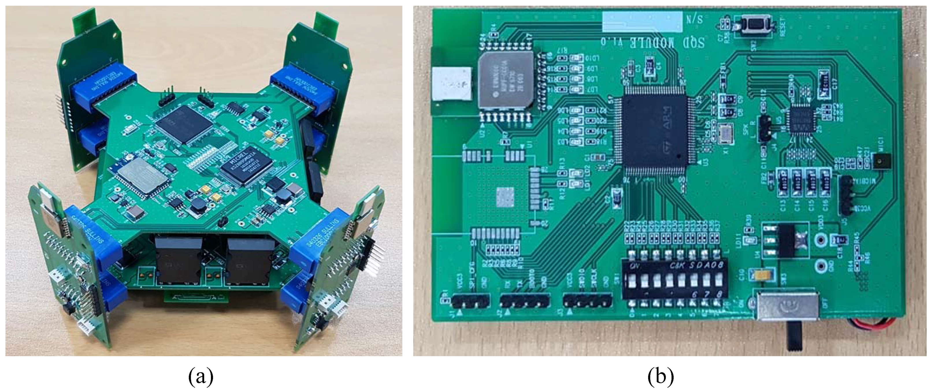
For the analysis of the wireless telecommunication positioning performance in closed spaces in buildings, UWB communication modules were fabricated to satisfy the IEEE 802.15.4a standard performance. Shown in Figure 1a is a base station module for communication with the UWB wireless module and Figure 1b is the UWB wireless module for communication with rescue workers. The main specifications of the UWB wireless communication modules are radiation power −10 dBm and RF Band 3.5 to 6.5 GHz as shown in Table 1. The frequency bands of the UWB wireless telecommunications modules are a total of six standard frequency channels as shown in Table 2, and support bandwidths from 499.2 MHz to 1331.2 MHz.
2.2. Experimental Conditions and Experimental Method
The developed wired/wireless base station module and UWB wireless telecommunication module are used to secure the communication lines between the rescue workers and the command post and to locate fire workers in cases where the existing communication base has become inoperable due to an indoor fire. Whether the communication signal is active or not should be determined. Figure 2 shows experiments for signal positioning measurement for the UWB wireless module. The outdoor open space is used as a test site for comparison and Figure 2 shows the program and operation screen for the evaluation of the positioning performance for a total of six indoor environments such as the corridor, closed indoor space where obstacles exist, stairs, and rooms where fire doors and glass doors have been closed. The details of the structural spaces for individual experimental environments are shown in Table 3.
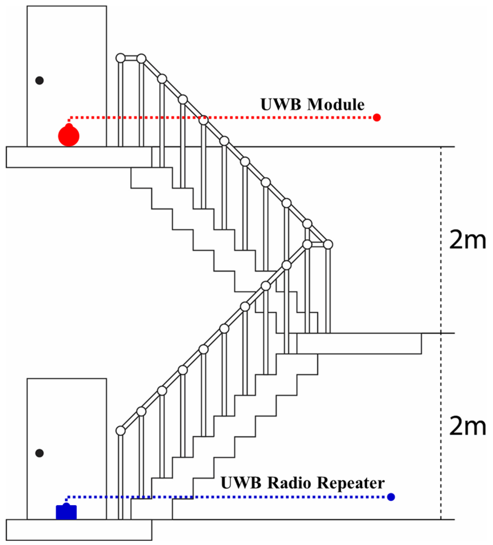
Figure 3 is a side view for positioning in vertical spaces with stairs. A UWB radio repeater was installed on the staircase landing, and UWB modules were installed on individual floors for measurement. For the positioning of the UWB wireless modules, signals were measured at every cm up to about 20 m from the wireless module repeater. The wireless modules were installed on the floor in the case of horizontal spaces and were installed on staircase landings in the case of environments where corridors, which are horizontal-vertical spaces as with stairs, are connected to stairs, to measure communication signals with telecommunication modules. In general buildings, the partitions between corridors and indoor spaces are fire walls or simple walls, and the doors are usually glass doors and fire doors. Therefore, to test the mutual communication between the corridors and the partitioned spaces, the glass door and the fire door were closed before the communication positioning experiment was conducted. The frequencies used for UWB signal positioning in the six types of spatial environments are UWB standard frequency 6 channels (1ch, 2ch 3ch, 4ch, 5ch, 7ch) as shown in Table 2, and the band ranges by frequency were also specified. Therefore, the performance was examined by evaluating the difference between the distance information calculated between modules by frequency as shown in Table 2 and actual distance information, and the distance measurement success rates.
The performance of the UWB wireless module was evaluated by calculating the distance information—the time for the wireless telecommunications module to receive the data packets transmitted from the wired/wireless base station module as the ToF (Time of Flight). In addition, 130-byte data packets were transmitted for distance measurement, and the distance measurement success rate was calculated by counting cases where all data were successfully received without radio wave reflection or errors occurring in data transmission/receiving. The numbers of time of attempts to transmit signals closer to 0 were judged as indicating better communication environments and performance.
3. Results and Discussion
3.1. Open Space
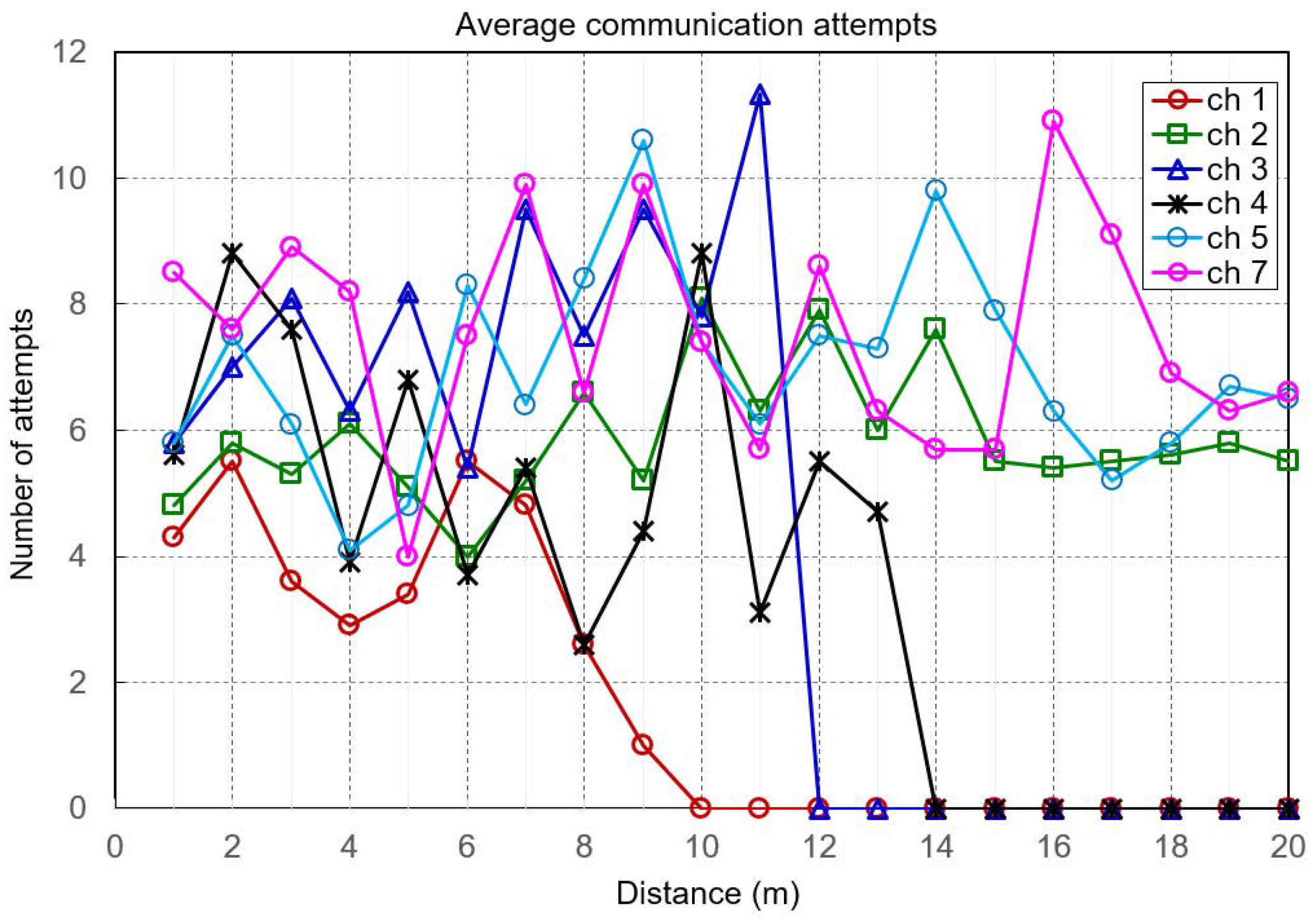
The positioning measurement in a horizontal open space where no obstacle is present was experimented in an open space with no obstacles to test the distance measurement performance. Since this experiment was conducted in a space with no obstructions, it becomes the reference experiment for future tests related to distance measurement and communication performance. The distance measurement showed the accuracy in cm units. When a positioning measurement was conducted in an open space with no obstacles, as shown in Figure 4, channels 2, 5 and 7 could measure distances 20 m and when they could measure distances, they succeeded in measuring the distances within 6–10 attempts. The communication and distance measurement performance was evaluated later based on the number of attempts made at the time of the test.
3.2. Corridor
When positioning was measured in a spatial environment with no obstacles in an enclosed corridor as shown in Figure 5, channels 2, 5 and 7 could measure distances up to 20 m while channels 1 and 3 could measure distances, approximately 5 m longer compared to open spaces and channel 4 showed a performance similar to that of open space. In addition, since the number of attempts for measurement of channels 2, 5 and 7, which could measure up to 20 m, are distributed in a range of 10 to 15, it could be seen that the signal performance in the communication environment was relatively lower as compared to open space.
3.3. Office
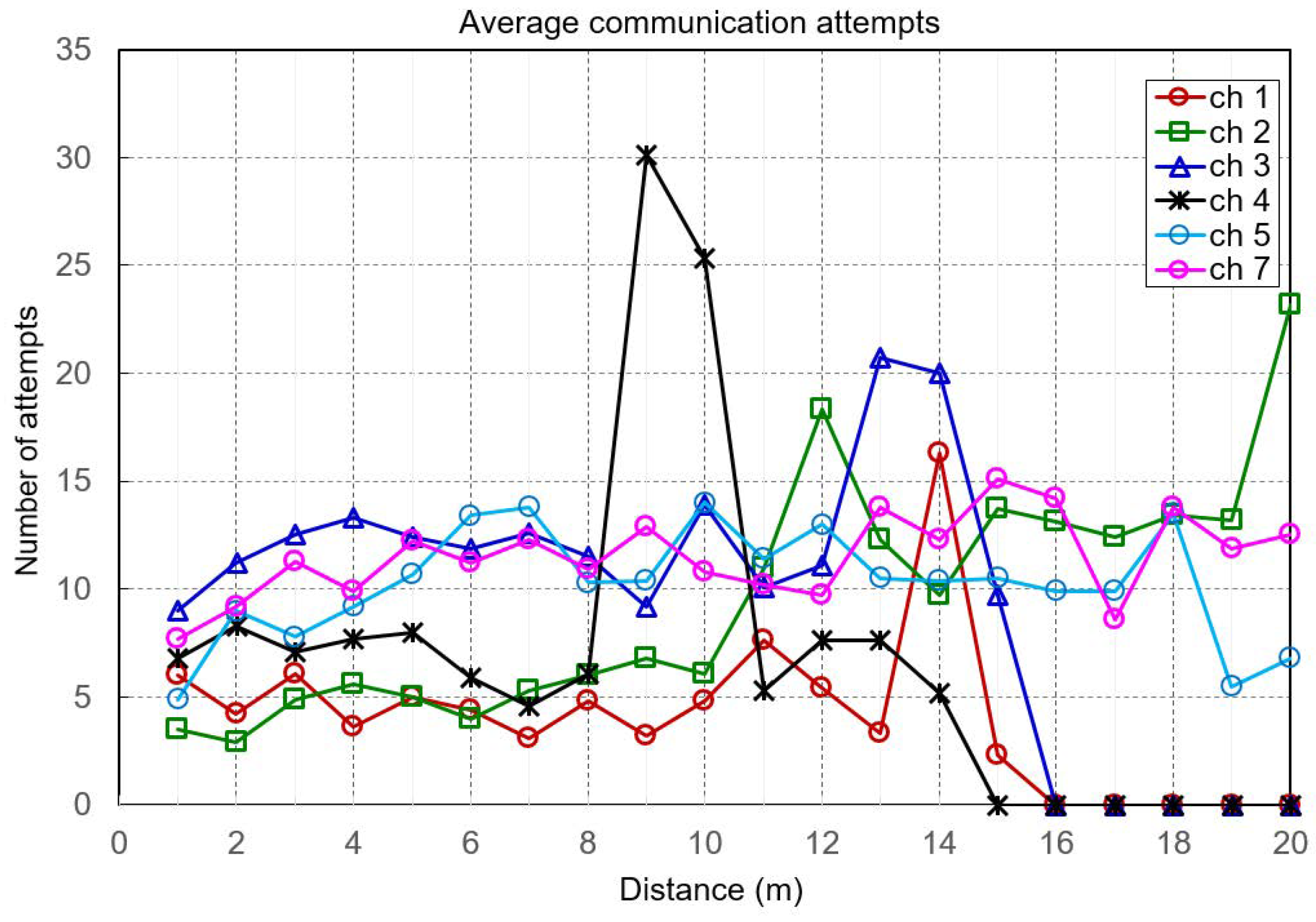
When positioning was measured in an indoor office environment where various furniture and fixtures existed in a closed space, as shown in Figure 6, channels 5 and 7 showed similar measurement performance as in open spaces while channels 1, 2 and 3 showed generally lower measurement performance.
Channel 4, however, showed improved measurement performance. Channel 4 had a bandwidth of about 1 GHz and showed higher distance measurement communication success rates by avoiding obstacles when the bandwidth was large. In addition, we found that the number of attempts increased instantaneously when the measurable distance decreased. This was identified to be attributable to the fact that more errors occurred when the distance measurement could not be performed.
3.4. Vertical Stairs
Positioning was measured in a vertical stairway space which is used as evacuation stairs in the closed space. As shown in Figure 3, the height between stairway landings for going down one floor made by simulating the experiment environment was 2 m and UWB modules were installed on the stairway landings for measurement. In the results of the positioning measurement, channel 7 measured the largest vertical height—reaching 4.5 m as shown in Table 4. Other channels were able to measure up to a height of 4 m.
3.5. Glass Door and Fire Door
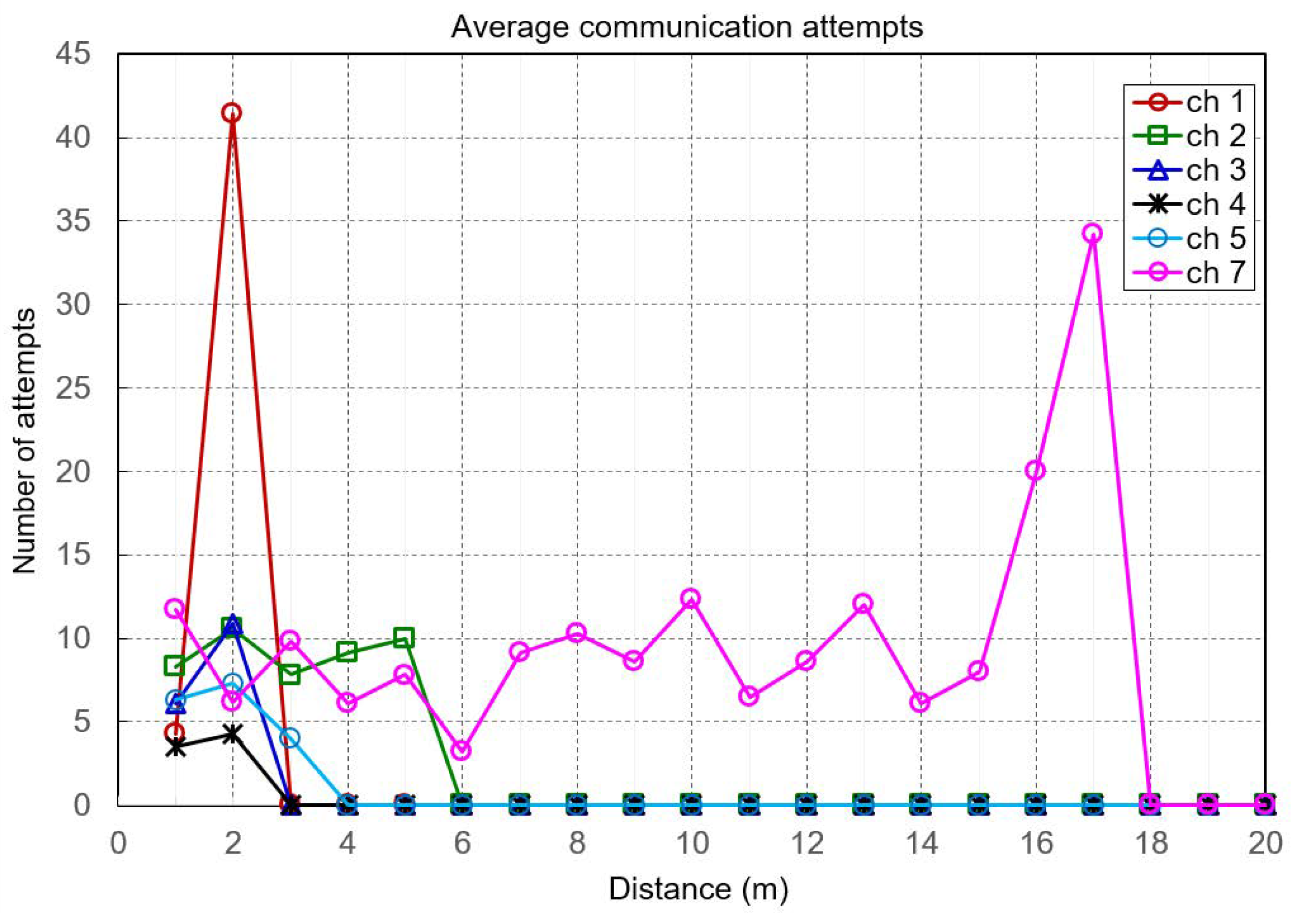
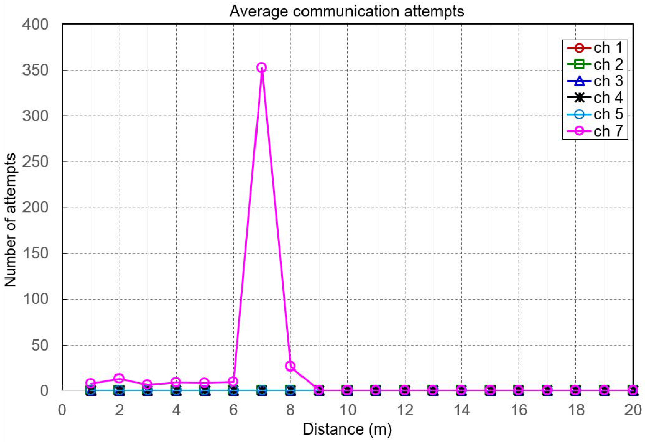
Positioning was measured in environments where office spaces were separated by corridors and reinforced concrete wall structures, glass doors, or fire doors were installed in closed spaces. The experiments were conducted in spaces divided by 8 mm thick tempered glass doors and 1.5 mm steel plate class A fire doors, respectively, as shown in Figure 7 and Figure 8. Channels 1 to 5 could not measure distances exceeding 5 m at the maximum in both the glass door and fire door environments, while channel 7 could measure distances up to 17 m in the glass door environment and up to 10 m in the fire door environment. However, the differences between the actual distance information and the measured distances were at least 2 m. This can be considered attributable to the fact that the glass door and the fire wall acted as obstacles leading to the multipath phenomenon of UWB radio waves so that the radio waves were transmitted/received after going around longer distances than the actual distance.
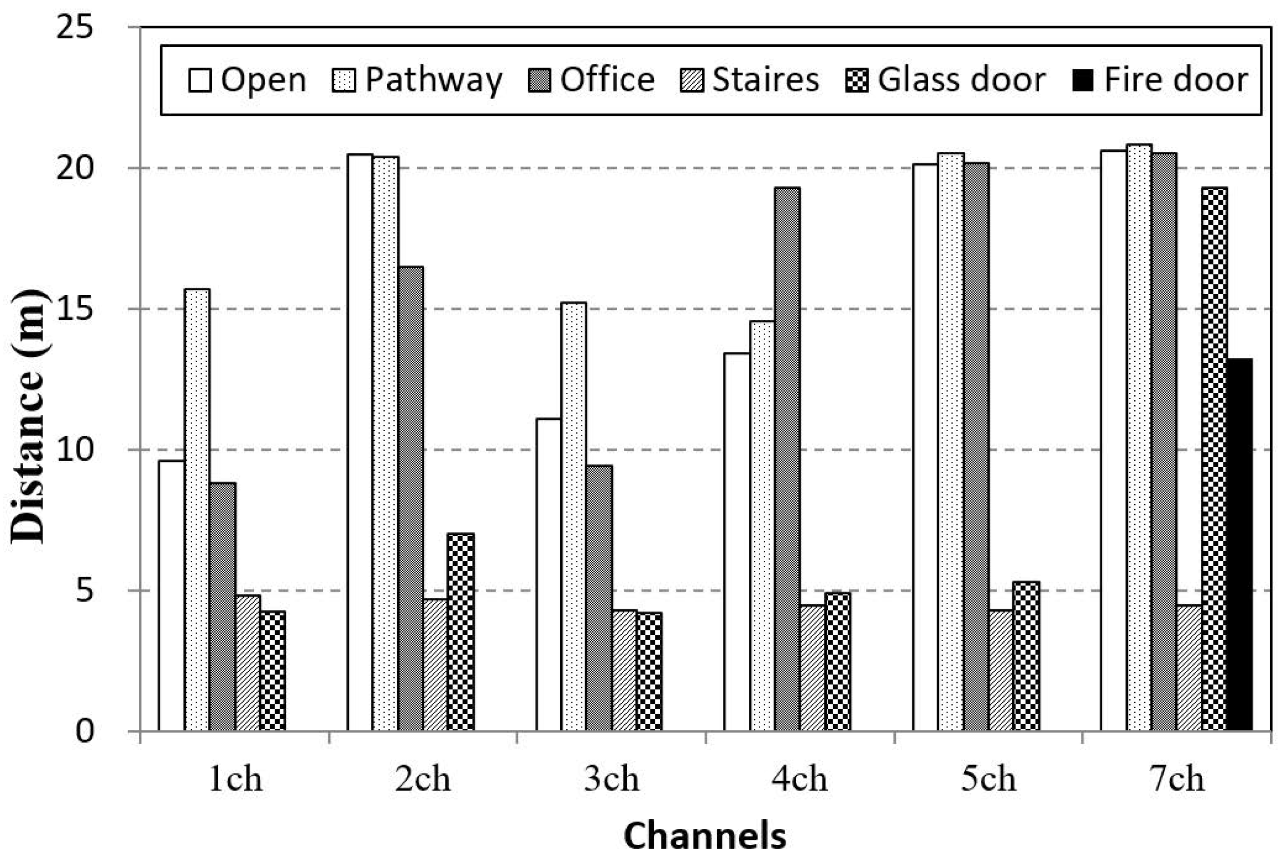
In the results of experiments in the above six environments, as shown in Figure 9, the communication performance and distance measurement performance of channel 7 with frequency 6489.6 MHz and bandwidth 1081.6 MHz were shown to be the best in general. It was identified that the number of attempts for communication increased when obstacles existed in the same closed space, leading to poorer communication performance and shorter measurable distances. Also, it could be seen that the communication reachable distance was remarkably shorter in emergency stairs, which is one of the main evacuation routes, as compared to other environments. In this study, the wired/wireless base station modules were arranged at an interval of about 20 m for measurement of communication with the wireless telecommunication module and distances and the errors between actual distances and the distances information obtained using ToF were found to be about 50 cm. It is considered that the distance errors can be reduced by accumulating indoor environment measurement analysis experimental data to used analyzed correction values.
4. Conclusions
When a fire or disaster has occurred, casualties can be minimized only in cases where firefighters and rescue and emergency workers immediately respond and conduct activities. However, in cases where the communication infrastructures have been destroyed, communication connections using TRS and LTE communication networks are impossible in closed spaces. The absence of a communication connection for rescue workers can lead to increases in casualties due to errors and delays in responding activities and can bring about risks to rescue workers’ safety.
When establishing the UWB communication network with a mobile base station and communication modules, it is possible to implement mutual position measurement between the communication modules as well as voice and video information transmission/reception. Thus, in this study, a UWB wireless communication network which transmits 100 Mbps digital data with low power over short distances was constructed. The communication positioning performance of the UWB communication module in enclosed indoor spaces was then evaluated.
Based on this study, the following conclusions on UWB communication module performance evaluation were drawn.
- Experiments in 6 spatial environments showed that the communication performance and distance measurement performance of channel 7 with frequency 6489.6 MHz and bandwidth 1081.6 MHz are the best.
- It was shown that the installation spaces for the UWB communication module could be 20 m as communication and distance measurement are possible in 20 m and that communication environments can be constructed in closed spaces when multi-channels are used.
- In particular, the communication distance in stairways was measured to be about 5 m, indicating that the communication module should be installed at intervals of two-story building height for smooth communication in vertical stairways.
- The communication distance was 4.5 m in the vertical stairways, revealing that a vertical communication connection would be possible when configuring a communication module for each second-floor landing of the stairwell.
- The distance measurement error between UWB communication modules using measured ToF values was about m.
In conclusion, the results of this study suggest that it is possible to construct a communication environment at a disaster site by using a communication network composed of UWB wired/wireless mobile base station and communication module. In addition, the developed communication network determined the relative distance position of the communication module, which would be helpful for indoor rescue activities. Hereafter, we will conduct experiments in the heat and smoke conditions related to indoor fires to investigate the possibility of using the UWB communication network.
Funding
This research received no external funding.
Conflicts of Interest
The author declares no conflict of interest.
References
- Perez-Calderon, L.J. Emergency Communications for Disaster Management. Asian Disaster Manag. News 2007, 13, 1–28. [Google Scholar]
- Ministry of Public Safety and Security. Verification of Test-Bed Result for Disaster Telecommunication Network Construction; Policy Resource of Ministry of Public Safety and Security; Ministry of Public Safety and Security: Sejong, Korea, 2014; p. 13.
- Yoo, Y.J.; Yo, M.K.; Kang, M.G. Trend Analysis of Global Public Safety Communicators & PS-LTE. Korean Soc. Internet Inf. 2015, 16, 33–38. [Google Scholar]
- Kim, Y.D.; Kim, Y.G.; Lee, S.H.; Kang, J.H.; An, J. Portable Fire Evacuation Guide Robot System. In Proceedings of the IEEE/RSJ International Conference on Robots and Systems (IROS 2009), St. Louis, MO, USA, 10–15 October 2009; pp. 2789–2794. [Google Scholar]
- Kim, Y.D.; Kang, J.H.; Sun, D.H.; Moon, J.I.; Ryuh, Y.S.; An, J. Design and Implementation of User-Friendly Remote Controllers for Rescue Robots Used at Fire Sites. In Proceedings of the IEEE/RSJ IROS, Taipei, Taiwan, 18–21 August 2010; pp. 377–382. [Google Scholar]
- Kim, Y.D.; Kwon, S.; Kim, H.J.; Park, J.W. A Fundamental Study on Wi-Fi Based Communication Methods for Enclosed Spaces. J. Korean Soc. Hazard Mitig. 2015, 15, 237–242. [Google Scholar] [CrossRef] [Green Version]
- Song, K.H. Transmission and Reflection Characteristics Measurements at the 60 GHz for the Various Obstacles. J. Korea Inst. Inf. Commun. Eng. 2008, 12, 25–32. [Google Scholar]
- Jung, M.S.; Bae, S.H.; Lee, B.S. Analysis of Building Material Reflection and Transmission Characterization for ISM band. Proc. KICS 2002, 2002, 212–215. [Google Scholar]
- Oh, S.B.; Kim, S.K.; Jee, S.W.; Lee, C.H.; Kim, H.G.; Sakong, S.H. A Study on the Response Characteristics of Fire Frequency 447 MHz and 2.4 GHz. Proc. KIFSE 2011, 2011, 31–34. [Google Scholar]
- Nagatani, K.; Kiribayashi, S.; Okada, Y.; Otake, K.; Yoshida, K.; Tadokoro, S.; Nishimura, T.; Yoshida, T.; Koyanagi, E.; Fukushima, M.; et al. Emergency response to the nuclear accident at the Fukushima Daiichi Nuclear Power Plants using mobile rescue robots. J. Field Robot. 2013, 30, 44–63. [Google Scholar] [CrossRef]
- Wylie-Green, M.P.; Ranta, P.A.; Salokannel, J. Multi-band OFDM UWB solution for IEEE 802.15. 3a WPANs. In Proceedings of the 2005 IEEE/Sarnoff Symposium on Advances in Wired and Wireless Communication, Princeton, NJ, USA, 18–19 April 2005; pp. 102–105. [Google Scholar]
- Gigl, T.; Janssen, G.J.; Dizdarevic, V.; Witrisal, K.; Irahhauten, Z. Analysis of a UWB indoor positioning system based on received signal strength. In Proceedings of the 4th Workshop on Positioning, Navigation and Communication (WPNC’07), Hannover, Germany, 22 March 2007; pp. 97–101. [Google Scholar]
- Chen, G.; Zhang, Y.; Xiao, L.; Li, J.; Zhou, L.; Zhou, S. Measurement-based RSS-multipath neural network indoor positioning technique. In Proceedings of the 2014 IEEE 27th Canadian Conference on Electrical and Computer Engineering (CCECE), Toronto, ON, Canada, 4–7 May 2014; pp. 1–7. [Google Scholar]
- The Institute of Electrical and Electronics Engineers (IEEE). IEEE Std 802.12.4a-2006, Amendment to 802.15.4-2006: Wireless Medium Access Control (MAC) and Pysical Layer (PHY) Specifications for Low-Rate Wireless Personal Area Networks (LR-WPANs); IEEE: New York, NY, USA, 2006. [Google Scholar]
Figure 1.
UWB wireless telecommunication module: (a) UWB radio repeater. (b) UWB module.

Figure 2.
Setup for UWB telecommunication module performance evaluation.

Figure 3.
A lateral view of stairs sector with installed UWB module.

Figure 4.
Result of ToF measurement for UWB at open sector.

Figure 5.
Result of ToF measurement for UWB at corridor sector in enclosed indoor.

Figure 6.
Result of ToF measurement for UWB at office sector in enclosed indoor.

Figure 7.
Result of ToF measurement for UWB at office and pathway sector with closed glass door.

Figure 8.
Result of ToF measurement for UWB at office and pathway sector with closed fire door.

Figure 9.
Result of telecommunication distance for UWB in each 6 sectors.


Table 1.
Main specifics of UWB wireless telecommunication module.
| Item | Specification |
|---|---|
| RF band | 3.5 GHz to 6.5 GHz |
| Data rates | 110 kbps, 850 kbps, 6.8 Mbps |
| Network | Rs-232, Spi, i2c etc |
| Weight | 52 g |
| Radiation Power | −10 dBm (0.1 mW) |
Table 2.
Frequency bands (MHz) of the UWB wireless modules by channel.
| Channel | Centre Frequency | Band |
|---|---|---|
| 1 | 3494.4 | 3244.8–3744.0 |
| 2 | 3993.6 | 3774.0–4243.2 |
| 3 | 4492.8 | 4243.2–4742.4 |
| 4 | 3993.6 | 3328.0–4659.2 |
| 5 | 6489.6 | 6240.0–6739.2 |
| 7 | 6489.6 | 5980.3–6998.9 |
Table 3.
Test environment in each 6 sectors for UWB RF module.
| Sector | Space | Obstacle | ||
|---|---|---|---|---|
| Width (m) | Length (m) | Height (m) | ||
| Open space | - | - | - | None |
| Pathway | 2.5 | 32.0 | 2.4 | None |
| Indoor room | 6.2 | 12.5 | 2.4 | Arranged normal OA furniture with 1.5 m height |
| Stairs room | 2.4 | 5.0 | 20.0 | Concrete stairs |
| Glass door | 1.8 | - | 2.1 | between pathway and office room |
| Fire door (steel) | 1.8 | - | 2.1 | between pathway and office room |
Table 4.
Distance and number for UWB contacting between UWB radio repeater and module.
| (a) Distance of ToF measurement | ||||||
| Test Number | 1ch | 2ch | 3ch | 4ch | 5ch | 7ch |
| 1 | 205 | 193 | 164 | 197 | 165 | 203 |
| 2 | 482 | 468 | 429 | 450 | 431 | 433 |
| 3 | 0 | 0 | 0 | 0 | 0 | 448 |
| 4 | 0 | 0 | 0 | 0 | 0 | 0 |
| (b) Trying number for contacting between UWB radio repeater and module | ||||||
| Test Number | 1ch | 2ch | 3ch | 4ch | 5ch | 7ch |
| 2 | 6.4 | 11.2 | 5.2 | 7.1 | 10.9 | 7.1 |
| 4 | 4.2 | 9.7 | 37.4 | 5.6 | 12.6 | 9.0 |
| 6 | 0 | 0 | 0 | 0 | 0 | 8.7 |
| 8 | 0 | 0 | 0 | 0 | 0 | 0 |
© 2018 by the author. Licensee MDPI, Basel, Switzerland. This article is an open access article distributed under the terms and conditions of the Creative Commons Attribution (CC BY) license (http://creativecommons.org/licenses/by/4.0/).
Share and Cite
MDPI and ACS Style
Kim, D. Performance of UWB Wireless Telecommunication Positioning for Disaster Relief Communication Environment Securing. Sustainability 2018, 10, 3857. https://0-doi-org.brum.beds.ac.uk/10.3390/su10113857
AMA Style
Kim D. Performance of UWB Wireless Telecommunication Positioning for Disaster Relief Communication Environment Securing. Sustainability. 2018; 10(11):3857. https://0-doi-org.brum.beds.ac.uk/10.3390/su10113857
Chicago/Turabian StyleKim, Donghyun. 2018. "Performance of UWB Wireless Telecommunication Positioning for Disaster Relief Communication Environment Securing" Sustainability 10, no. 11: 3857. https://0-doi-org.brum.beds.ac.uk/10.3390/su10113857
Note that from the first issue of 2016, this journal uses article numbers instead of page numbers. See further details here.