Using Static Concentrator Technology to Achieve Global Energy Goal

 ,
,  ,
,  ,
,  , ,
, ,
Abstract
:1. Introduction
2. Target, Materials and Methods
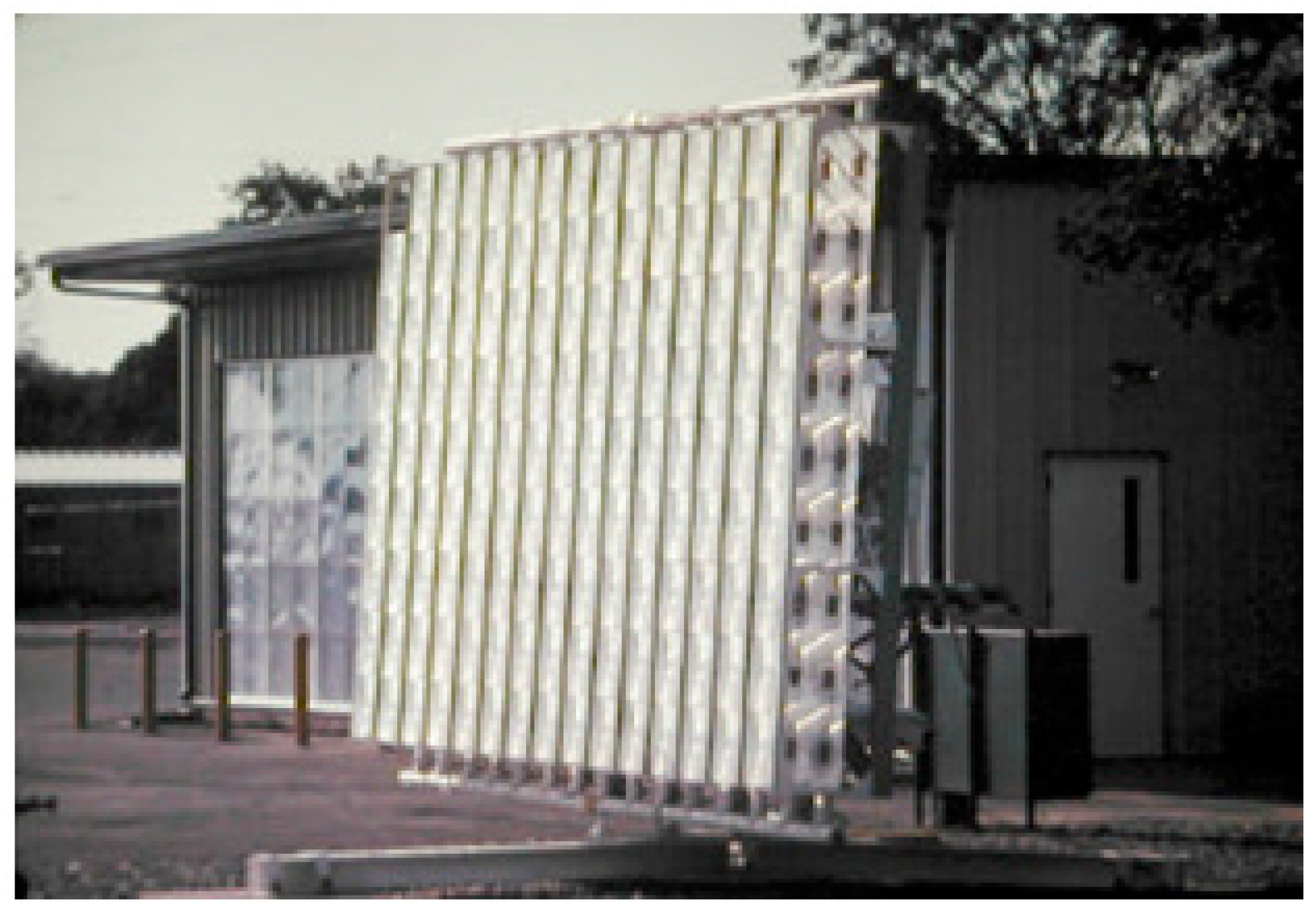
3. Solar Concentrator: A Historic Overview
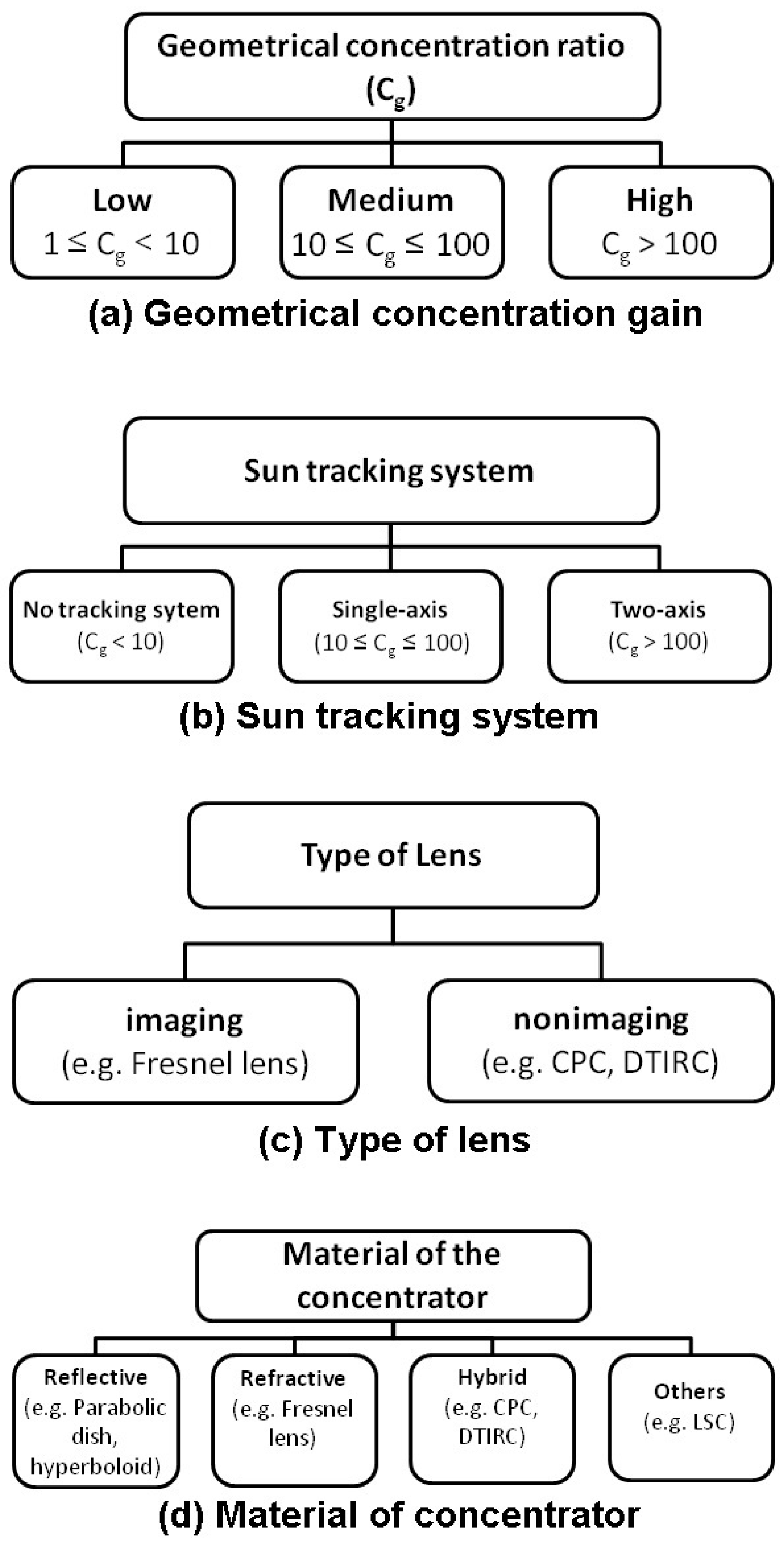
4. Low Concentrating Photovoltaics: Technology Overview
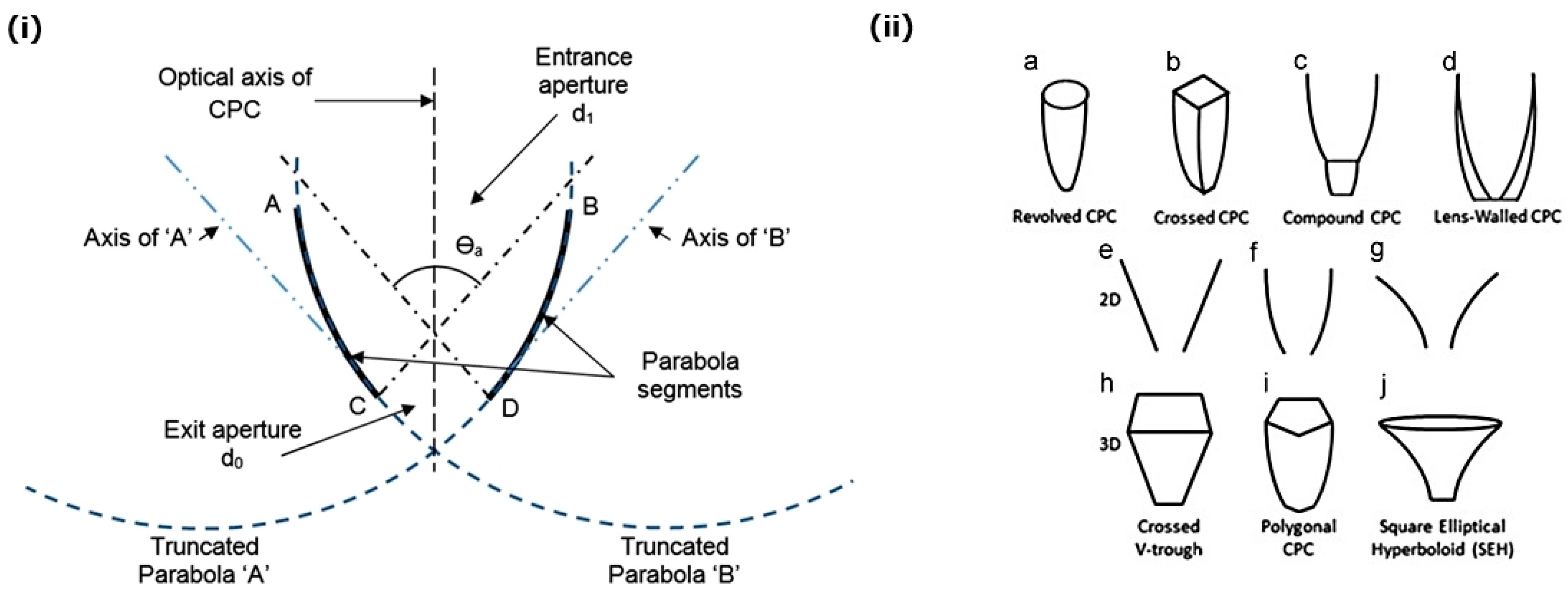
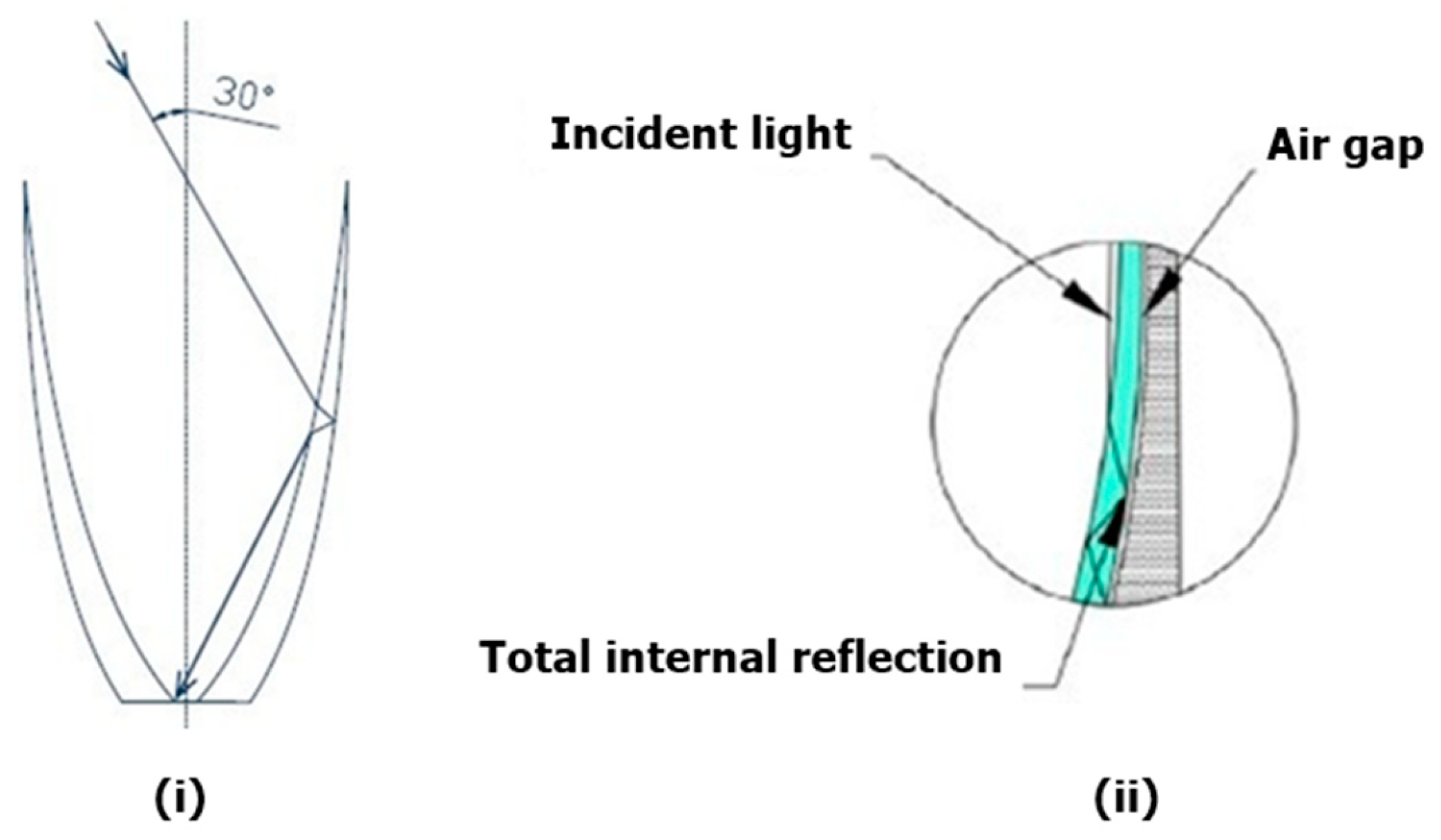
4.1. Compound Parabolic Concentrator
4.2. V-trough Solar Concentrator
4.3. Elliptical Concentrators
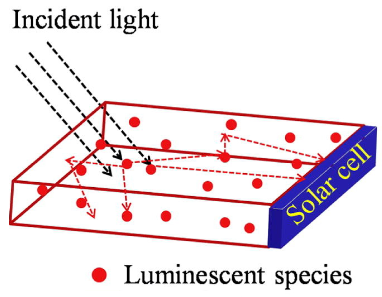
4.4. Luminescent Concentrating Systems
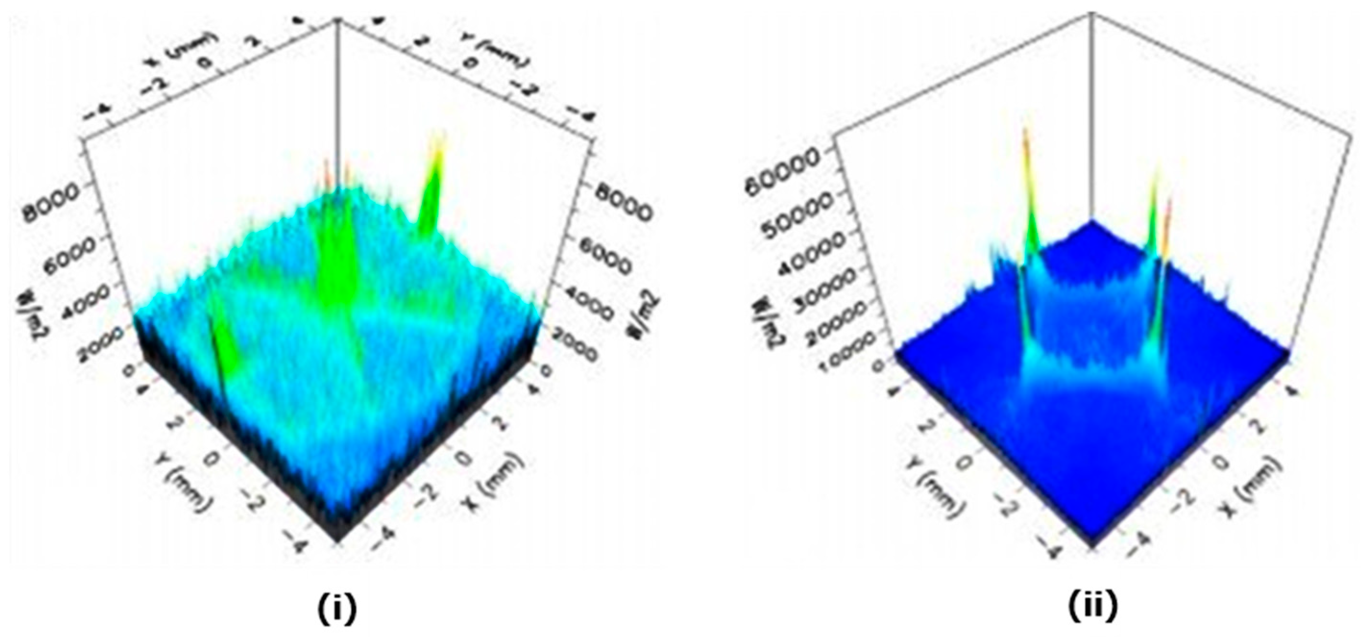
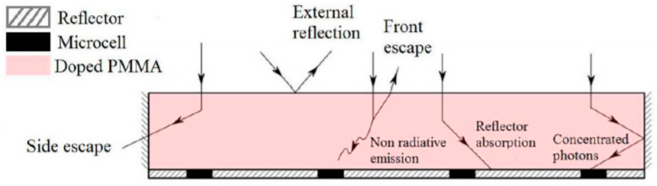
4.4.1. Luminescent Solar Concentrator
4.4.2. Quantum Dot Solar Concentrator
5. Discussions
6. Conclusions
- Despite the SDG 7 goal to provide access to affordable energy for all by 2030, the IEA predicts that 700 million people will still lack access to electricity by 2030, significantly compromising their quality of life.
- Global initiatives such as the African Renewable Energy initiative (AREI) and the UN’s Sustainable Energy for All initiative will play a great part in accelerating the adoption of solar energy, which is predicted to generate 13% of the world’s electricity by 2030.
- Although the cost of solar panels reaching a low of $0.71/W in China, the technology is still considered prohibitively expensive in developing countries that lack the economies of scale.
- Solar concentrators can potentially reduce the cost of solar installations by 36.5% by replacing expensive PV material with cheaper reflective or refractive material. Static concentrators are particularly promising as they can operate without tracking thus reducing maintenance and cost demands.
- CPCs offer high acceptance angle but suffer from irradiance distribution and increases in temperature. Nanofluids are gauging increasing interest as solution to reduce the gain within solar concentrators, but they are still not economically feasible and are not suitable for turbulent cooling.
- V-trough concentrators can operate without tilt adjustment given a concentration ratio below 2X but they suffer from non-uniform illumination most of the year
- LSCs do not suffer from hot spots like CPC but they have significantly lower efficiency than the other reviewed concentrators because of the presence of losses due to escape cone, reflection on the surface, larger optical path, scattering, and reabsorption.
- This paper argues that static solar concentrators can help achieve the SDG 7 goal by 2030 by reducing the cost of solar, which make it economically and financially sustainable. The LCA studies also indicated that the CPV has much lower embodied energy requirement during manufacturing process and produces much lower CO2 emission throughout their life time when compared with the traditional PV system, making the system more desirable.
- However, many challenges such as the irradiance distribution in CPC, the non-uniform illumination in V-trough and low efficiencies of luminescent concentrators need to be overcome if concentrators are to truly offer a more cost-effective solution than standard PV panels. A comprehensive economic, social and technical overview of static solar concentrator and their potential to help achieved SDG 7 goals is provided here to support this viewpoint.
Author Contributions
Funding
Conflicts of Interest
References
- Ómarsdóttir, M.; Lindner, R. We Need Concrete Targets for Sustainable Energy. In Proceedings of the United Nations Sustainable Development Summit, New York, NY, USA, 25–27 September 2015. [Google Scholar]
- IEA. World Energy Outlook 2018; IEA: Paris, France, 2018. [Google Scholar]
- World Bank Independent Evaluation Group. The Welfare Impact of Rural Electrification: A Reassessment of the Costs and Benefits; The World Bank: Washington, DC, USA, 2008. [Google Scholar]
- UNFCCC. Adoption of the Paris Agreement. In Proceedings of the Conference of the Parties. Proposal by the President, Bonn, Germany, 11–30 December 2015; pp. 1–32. [Google Scholar]
- IEA. Energy and Climate Change; IEA: Paris, France, 2015. [Google Scholar]
- United Nations. Goal 7: Ensure Access to Affordable, Reliable, Sustainable and Modern Energy for All. Available online: http://www.un.org/sustainabledevelopment/energy/ (accessed on 7 December 2016).
- United Nations. Sustainable Development Knowledge Platform. Available online: https://sustainabledevelopment.un.org/sdg7 (accessed on 7 December 2016).
- IRENA. Sustainable Energy for All and SDG 7 in Focus. Available online: https://irenanewsroom.org/2015/09/30/sustainable-energy-for-all-and-sdg-7-in-focus/ (accessed on 7 December 2016).
- Markvart, T. Solar Electricity, 2nd ed.; Wiley: Chichester, UK, 2000; ISBN 0471988537. [Google Scholar]
- IRENA. Renewable Capacity Statistics 2018; IRENA: Abu Dhabi, UAE, 2018. [Google Scholar]
- Gielen, D.; Kempener, R.; Taylor, M.; Boshell, F.; Seleem, A. Letting in the Light: How Solar Photovoltaic Will Revolutionise the Electricity System; IRENA: Abu Dhabi, UAE, 2016. [Google Scholar]
- IEA-PVPS. Trends 2018 in Photovoltaic Applications; IEA-PVPS: St. Ursen, Switzerland, 2018. [Google Scholar]
- IRENA. Renewable Energy Technologies: Cost Analysis Series - Solar Photovoltaics; IRENA: Abu Dhabi, UAE, 2012. [Google Scholar]
- Lo, C.-C.; Wang, C.-H.; Huang, C.-C. The national innovation system in the Taiwanese photovoltaic industry: A multiple stakeholder perspective. Technol. Forecast. Soc. Change 2013, 80, 893–906. [Google Scholar] [CrossRef]
- Goodrich, A.; Hacke, P.; Wang, Q.; Sopori, B.; Margolis, R.; James, T.L.; Woodhouse, M. A wafer-based monocrystalline silicon photovoltaics road map: Utilizing known technology improvement opportunities for further reductions in manufacturing costs. Sol. Energy Mater. Sol. Cells 2013, 114, 110–135. [Google Scholar] [CrossRef]
- Munir, A.B.; Muhammad-Sukki, F.; Bani, N.A. Renewables: Solar energy needs focus. Nature 2016, 529, 466. [Google Scholar] [CrossRef]
- Swanson, R.M. Photovoltaic Concentrators. In Handbook of Photovoltaic Science and Engineering; John Wiley and Sons, Ltd: New York, NY, USA, 2003; pp. 449–503. ISBN 9780470014004. [Google Scholar]
- Muhammad-Sukki, F.; Ramirez-iniguez, R.; Mcmeekin, S.G.; Stewart, B.G.; Clive, B. Solar concentrators. Int. J. Appl. Sci. 2010, 1, 1–15. [Google Scholar]
- Chemisana, D. Building Integrated Concentrating Photovoltaics: A review. Renew. Sustain. Energy Rev. 2011, 15, 603–611. [Google Scholar] [CrossRef]
- Horne, S. Concentrating photovoltaic (CPV) systems and applications. Conc. Sol. Power Technol. 2012, 323–361. [Google Scholar]
- Jaaz, A.H.; Hasan, H.A.; Sopian, K.; Haji Ruslan, M.H.B.; Zaidi, S.H. Design and development of compound parabolic concentrating for photovoltaic solar collector: Review. Renew. Sustain. Energy Rev. 2017, 76, 1108–1121. [Google Scholar] [CrossRef]
- Ferrara, M.A.; Striano, V.; Coppola, G.; Ferrara, M.A.; Striano, V.; Coppola, G. Volume Holographic Optical Elements as Solar Concentrators: An Overview. Appl. Sci. 2019, 9, 193. [Google Scholar] [CrossRef]
- Madala, S.; Boehm, R.F. A review of nonimaging solar concentrators for stationary and passive tracking applications. Renew. Sustain. Energy Rev. 2017, 71, 309–322. [Google Scholar] [CrossRef]
- Freier, D.; Ramirez-Iniguez, R.; Jafry, T.; Muhammad-Sukki, F.; Gamio, C. A review of optical concentrators for portable solar photovoltaic systems for developing countries. Renew. Sustain. Energy Rev. 2018, 90, 957–968. [Google Scholar] [CrossRef] [Green Version]
- Lamnatou, C.; Chemisana, D. Concentrating solar systems: Life Cycle Assessment (LCA) and environmental issues. Renew. Sustain. Energy Rev. 2017, 78, 916–932. [Google Scholar] [CrossRef] [Green Version]
- Kraemer, S. Cogenra: Set to meet SunShot 5 Cents per Kilowatt-hour. Available online: http://news.pv-insider.com/concentrated-pv/cogenra-set-meet-sunshot-5-cents-kilowatt-hour (accessed on 11 December 2014).
- Sarmah, N.; Richards, B.S.; Mallick, T.K. Design, development and indoor performance analysis of a low concentrating dielectric photovoltaic module. Sol. Energy 2014, 103, 390–401. [Google Scholar] [CrossRef]
- IEA-PVPS. Trends 2016 in Photovoltaic Applications; IEA-PVPS: St. Ursen, Switzerland, 2016. [Google Scholar]
- Solar Trade Association. Cost Reduction Potential of Large-Scale Solar PV; STA: London, UK, 2014. [Google Scholar]
- The ECO Experts. Solar Panel Cost. Available online: http://www.theecoexperts.co.uk/how-much-do-solar-panels-cost-uk (accessed on 11 December 2016).
- Hosenuzzaman, M.; Rahim, N.A.; Selvaraj, J.; Hasanuzzaman, M.; Malek, A.B.M.A.; Nahar, A. Global prospects, progress, policies, and environmental impact of solar photovoltaic power generation. Renew. Sustain. Energy Rev. 2015, 41, 284–297. [Google Scholar] [CrossRef]
- Sellami, N. Design and Characterisation of a Novel Translucent Solar Concentrator. Ph.D. Thesis, Heriot-Watt University, Edinburgh, UK, 2013. [Google Scholar]
- Solar Energy for Homes. Solar Concentrators are the Future of Renewable Energy. Available online: http://www.solar-energy-for-homes.com/solar-concentrator.html (accessed on 11 December 2016).
- Cuce, E.; Cuce, P.M. A comprehensive review on solar cookers. Appl. Energy 2013, 102, 1399–1421. [Google Scholar] [CrossRef]
- Scartezzini, J.-L. Solar Energy Journal - Special issue CISBAT 2003. Sol. Energy 2005, 79, 107–109. [Google Scholar] [CrossRef]
- LAGI. The 19th Century Solar Engines of Augustin Mouchot, Abel Pifre, and John Ericsson. Available online: http://landartgenerator.org/blagi/archives/2004 (accessed on 1 January 2017).
- Chapin, D.M.; Fuller, C.S.; Pearson, G.L. A new silicon p-n junction photocell for converting solar radiation into electrical power. J. Appl. Phys. 1954, 25, 676. [Google Scholar] [CrossRef]
- Nelson, J. The Physics of Solar Cells; Imperial College Press: London, UK, 2002; ISBN 978-1-86094-340-9. [Google Scholar]
- Ralph, E.L. Use of concentrated sunlight with solar cells for terrestrial applications. Sol. Energy 1966, 10, 67–71. [Google Scholar] [CrossRef]
- Sala, G.; Luque, A. Past experiences and new challenges of PV concentrators. In Concentrator Photovoltaics SE - 1; Luque, A.L., Viacheslav, A., Eds.; Springer Series in Optical Sciences; Springer: Berlin, Heidelberg, 2007; Volume 130, pp. 1–23. ISBN 978-3-540-68796-2. [Google Scholar]
- Maish, A.B. Progress in the Concentrator Initiative Program. In Proceedings of the Conference Record of the Twenty Third IEEE Photovoltaic Specialists Conference - 1993 (Cat. No.93CH3283-9), Louisville, KY, USA, 10–14 May 1993; pp. 1203–1208. [Google Scholar]
- Luque, A.; Sala, G.; Arboiro, J.C.; Bruton, T.; Cunningham, D.; Mason, N. Some results of the EUCLIDES photovoltaic concentrator prototype. Prog. Photovoltaics Res. Appl. 1997, 5, 195–212. [Google Scholar] [CrossRef]
- Sala, G.; Arboiro, J.C.; Luque, A.; Zamorano, J.C.; Minano, J.C.; Dramsch, C.; Bruton, T.; Cunningham, D. The EUCLIDES prototype: An efficient parabolic trough for PV concentration. In Proceedings of the Conference Record of the Twenty Fifth IEEE Photovoltaic Specialists Conference – 1996, Washington, DC, USA, 13–17 May 1996; 1996; pp. 1207–1210. [Google Scholar]
- Sala, G.; Arboiro, J.C.; Luque, A.; Antón, I.; Mera, E.; Camblor, E.; Datta, P.; Gasson, M.P.; Mason, N.B.; Heasman, K.C.; et al. 480 kWpeak EUCLIDES TM concentrator power plant using parabolic troughs. In Proceedings of the 2nd World Conference on Photovoltaic Solar Energy Conversion, Vienna, Austria; 1998; pp. 1963–1968. [Google Scholar]
- Vivar, M.; Antón, I.; Pachón, D.; Sala, G. Third-generation EUCLIDES concentrator results. Prog. Photovoltaics Res. Appl. 2012, 20, 356–371. [Google Scholar] [CrossRef]
- Feuermann, D.; Gordon, J.M. Analysis of a two-stage linear Fresnel reflector solar concentrator. J. Sol. Energy Eng. 1991, 113, 272–279. [Google Scholar] [CrossRef]
- Brunotte, M.; Goetzberger, A.; Blieske, U. Two-stage concentrator permitting concentration factors up to 300x with one-axis tracking. Sol. Energy 1996, 56, 285–300. [Google Scholar] [CrossRef]
- Benitez, P.; Minano, J.C.; Garcia, R.; Mohedano Arroyo, R. Contactless two-stage solar concentrators for tubular absorber. In Proceedings of the Optical Science, Engineering and Instrumentation ’97; Winston, R., Ed.; International Society for Optics and Photonics: San Diego, CA, USA, 1997; pp. 205–216. [Google Scholar]
- Philipps, S.P.; Bett, A.W.; Horowitz, K.; Kurtz, S. Current Status of Concentrator Photovoltaic (CPV) Technology; Fraunhofer ISE: Freiburg, Germany, 2016. [Google Scholar]
- CPV Consortium. CPV Technology. Available online: http://cpvconsortium.org/cpv_technology (accessed on 9 January 2017).
- Abu-Bakar, S.H. Novel Rotationally Asymmetrical Solar Concentrator for the Building Integrated Photovoltaic System. Ph.D. Thesis, Glasgow Caledonian University, Glasgow, UK, 2016. [Google Scholar]
- Lamnatou, C.; Baig, H.; Chemisana, D.; Mallick, T.K. Life cycle energy analysis and embodied carbon of a linear dielectric-based concentrating photovoltaic appropriate for building-integrated applications. Energy Build. 2015, 107, 366–375. [Google Scholar] [CrossRef]
- Menoufi, K.; Chemisana, D.; Rosell, J.I. Life cycle assessment of a building integrated concentrated photovoltaic scheme. Appl. Energy 2013, 111, 505–514. [Google Scholar] [CrossRef]
- Zawadzki, P.; Muhammad-Sukki, F.; Abu-Bakar, S.H.; Bani, N.A.; Abubakar Mas’ud, A.; Ardila-Rey, J.A.; Munir, A.B.; Mohd Yasin, S.H. Life Cycle Assessment of a Static Concentrator. In Proceedings of the 14th International UMT Annual Symposium (UMTAS), Terengganu, Malaysia, 23–25 July 2019; pp. 1–9, (Accepted). [Google Scholar]
- Mateen, F.; Ali, M.; Oh, H.; Hong, S.-K. Nitrogen-doped carbon quantum dot based luminescent solar concentrator coupled with polymer dispersed liquid crystal device for smart management of solar spectrum. Sol. Energy 2019, 178, 48–55. [Google Scholar] [CrossRef]
- Masuda, T.; Araki, K.; Okumura, K.; Urabe, S.; Kudo, Y.; Kimura, K.; Nakado, T.; Sato, A.; Yamaguchi, M. Static concentrator photovoltaics for automotive applications. Sol. Energy 2017, 146, 523–531. [Google Scholar] [CrossRef]
- Abu-Bakar, S.H.; Muhammad-Sukki, F.; Ramirez-Iniguez, R.; Mallick, T.K.; Munir, A.B.; Mohd Yasin, S.H.; Abdul Rahim, R. Rotationally asymmetrical compound parabolic concentrator for concentrating photovoltaic applications. Appl. Energy 2014, 136, 363–372. [Google Scholar] [CrossRef]
- Chaves, J. Introduction to Nonimaging Optics, 2nd ed.; CRC Press: Boca Raton, FL, USA, 2015; ISBN 978-1420054293. [Google Scholar]
- Sellami, N.; Mallick, T.K.; McNeil, D.A. Optical characterisation of 3-D static solar concentrator. Energy Convers. Manag. 2012, 64, 579–586. [Google Scholar] [CrossRef]
- Shanks, K.; Senthilarasu, S.; Mallick, T.K. Optics for concentrating photovoltaics: Trends, limits and opportunities for materials and design. Renew. Sustain. Energy Rev. 2016, 60, 394–407. [Google Scholar] [CrossRef] [Green Version]
- Su, Y.; Pei, G.; Riffat, S.B.; Huang, H. Radiance/Pmap simulation of a novel lens-walled compound parabolic concentrator (lens-walled CPC). Energy Procedia 2012, 14, 572–577. [Google Scholar] [CrossRef] [Green Version]
- Su, Y.; Riffat, S.B.; Pei, G. Comparative study on annual solar energy collection of a novel lens-walled compound parabolic concentrator (lens-walled CPC). Sustain. Cities Soc. 2012, 4, 35–40. [Google Scholar] [CrossRef]
- Li, G.; Pei, G.; Su, Y.; Wang, Y.; Ji, J. Design and investigation of a novel lens-walled compound parabolic concentrator with air gap. Appl. Energy 2014, 125, 21–27. [Google Scholar]
- Xuan, Q.; Li, G.; Pei, G.; Ji, J.; Su, Y.; Zhao, B. Optimization design and performance analysis of a novel asymmetric compound parabolic concentrator with rotation angle for building application. Sol. Energy 2017, 158, 808–818. [Google Scholar]
- Lu, W.; Wu, Y.; Eames, P. Design and development of a Building Façade Integrated Asymmetric Compound Parabolic Photovoltaic concentrator (BFI-ACP-PV). Appl. Energy 2018, 220, 325–336. [Google Scholar] [CrossRef]
- Meng, X.; Sellami, N.; Knox, A.R.; Montecucco, A.; Siviter, J.; Mullen, P.; Ashraf, A.; Samarelli, A.; Llin, L.F.; Paul, D.J.; et al. A novel absorptive/reflective solar concentrator for heat and electricity generation: An optical and thermal analysis. Energy Convers. Manag. 2016, 114, 142–153. [Google Scholar] [CrossRef] [Green Version]
- Sardarabadi, M.; Passandideh-Fard, M.; Zeinali Heris, S. Experimental investigation of the effects of silica/water nanofluid on PV/T (photovoltaic thermal units). Energy 2014, 66, 264–272. [Google Scholar] [CrossRef]
- Yazdanifard, F.; Ebrahimnia-Bajestan, E.; Ameri, M. Performance of a parabolic trough concentrating photovoltaic/thermal system: Effects of flow regime, design parameters, and using nanofluids. Energy Convers. Manag. 2017, 148, 1265–1277. [Google Scholar] [CrossRef]
- Sellami, N.; Mallick, T.K. Optical characterisation and optimisation of a static Window Integrated Concentrating Photovoltaic system. Sol. Energy 2013, 91, 273–282. [Google Scholar] [CrossRef]
- Baig, H.; Sellami, N.; Mallick, T.K. Trapping light escaping from the edges of the optical element in a Concentrating Photovoltaic system. Energy Convers. Manag. 2015, 90, 238–246. [Google Scholar] [CrossRef]
- Sabry, M.; Abdel-Hadi, Y.A.; Ghitas, A. PV-integrated CPC for transparent façades. Energy Build. 2013, 66, 480–484. [Google Scholar] [CrossRef]
- Saleh Ali, I.M.; O’Donovan, T.S.; Reddy, K.S.; Mallick, T.K. An optical analysis of a static 3-D solar concentrator. Sol. Energy 2013, 88, 57–70. [Google Scholar] [CrossRef]
- Tian, M.; Zhang, L.; Su, Y.; Xuan, Q.; Li, G.; Lv, H. An evaluation study of miniature dielectric crossed compound parabolic concentrator (dCCPC) panel as skylights in building energy simulation. Sol. Energy 2019, 179, 264–278. [Google Scholar] [CrossRef]
- Sellami, N.; Mallick, T.K. Optical efficiency study of PV Crossed Compound Parabolic Concentrator. Appl. Energy 2013, 102, 868–876. [Google Scholar] [CrossRef]
- Abu-Bakar, S.H.; Muhammad-Sukki, F.; Freier, D.; Ramirez-Iniguez, R.; Mallick, T.K.; Munir, A.B.; Mohd Yasin, S.H.; Abubakar Mas’ud, A.; Md Yunus, N. Performance analysis of a novel rotationally asymmetrical compound parabolic concentrator. Appl. Energy 2015, 154, 221–231. [Google Scholar] [CrossRef]
- Hatwaambo, S.; Hakansson, H.; Roos, A.; Karlsson, B. Mitigating the non-uniform illumination in low concentrating CPCs using structured reflectors. Sol. Energy Mater. Sol. Cells 2009, 93, 2020–2024. [Google Scholar] [CrossRef]
- Tang, R.; Liu, X. Optical performance and design optimization of V-trough concentrators for photovoltaic applications. Sol. Energy 2011, 85, 2154–2166. [Google Scholar] [CrossRef]
- Paul, D.I. Theoretical and Experimental Optical Evaluation and Comparison of Symmetric 2D CPC and V-Trough Collector for Photovoltaic Applications. Int. J. Photoenergy 2015, 2015, 1–13. [Google Scholar] [CrossRef]
- Michael, J.J.; Iqbal, S.M.; Iniyan, S.; Goic, R. Enhanced electrical performance in a solar photovoltaic module using V-trough concentrators. Energy 2018, 148, 605–613. [Google Scholar] [CrossRef]
- Kerrouche, A.; Hardy, D.A.; Ross, D.; Richards, B.S. Luminescent solar concentrators: From experimental validation of 3D ray-tracing simulations to coloured stained-glass windows for BIPV. Sol. Energy Mater. Sol. Cells 2014, 122, 99–106. [Google Scholar] [CrossRef] [Green Version]
- Joudrier, A.-L.; Proise, F.; Grapin, R.; Pelouard, J.-L.; Guillemoles, J.-F. Modeling and Fabrication of Luminescent Solar Concentrators towards Photovoltaic Devices. Energy Procedia 2014, 60, 173–180. [Google Scholar] [CrossRef] [Green Version]
- Wu, Y.; Connelly, K.; Liu, Y.; Gu, X.; Gao, Y.; Chen, G.Z. Smart solar concentrators for building integrated photovoltaic façades. Sol. Energy 2016, 133, 111–118. [Google Scholar] [CrossRef]
- Tummeltshammer, C.; Taylor, A.; Kenyon, A.J.; Papakonstantinou, I. Losses in luminescent solar concentrators unveiled. Sol. Energy Mater. Sol. Cells 2016, 144, 40–47. [Google Scholar] [CrossRef]
- Chandra, S.; McCormack, S.J.; Kennedy, M.; Doran, J. Quantum dot solar concentrator: Optical transportation and doping concentration optimization. Sol. Energy 2015, 115, 552–561. [Google Scholar] [CrossRef]
- Gallagher, S.J.; Norton, B.; Eames, P.C. Quantum dot solar concentrators: Electrical conversion efficiencies and comparative concentrating factors of fabricated devices. Sol. Energy 2007, 81, 813–821. [Google Scholar] [CrossRef]


| Project | Location | Capacity (MW) |
|---|---|---|
| Golmud 2 | Golmud, China | 79.83 |
| Golmud 1 | Golmud, China | 57.96 |
| Touwsrivier | Touwsrivier, South Africa | 44.19 |
| Alamosa Solar Project | Colorado, USA | 35.28 |
| Hami Phase II | Hami, China | 5.88 |
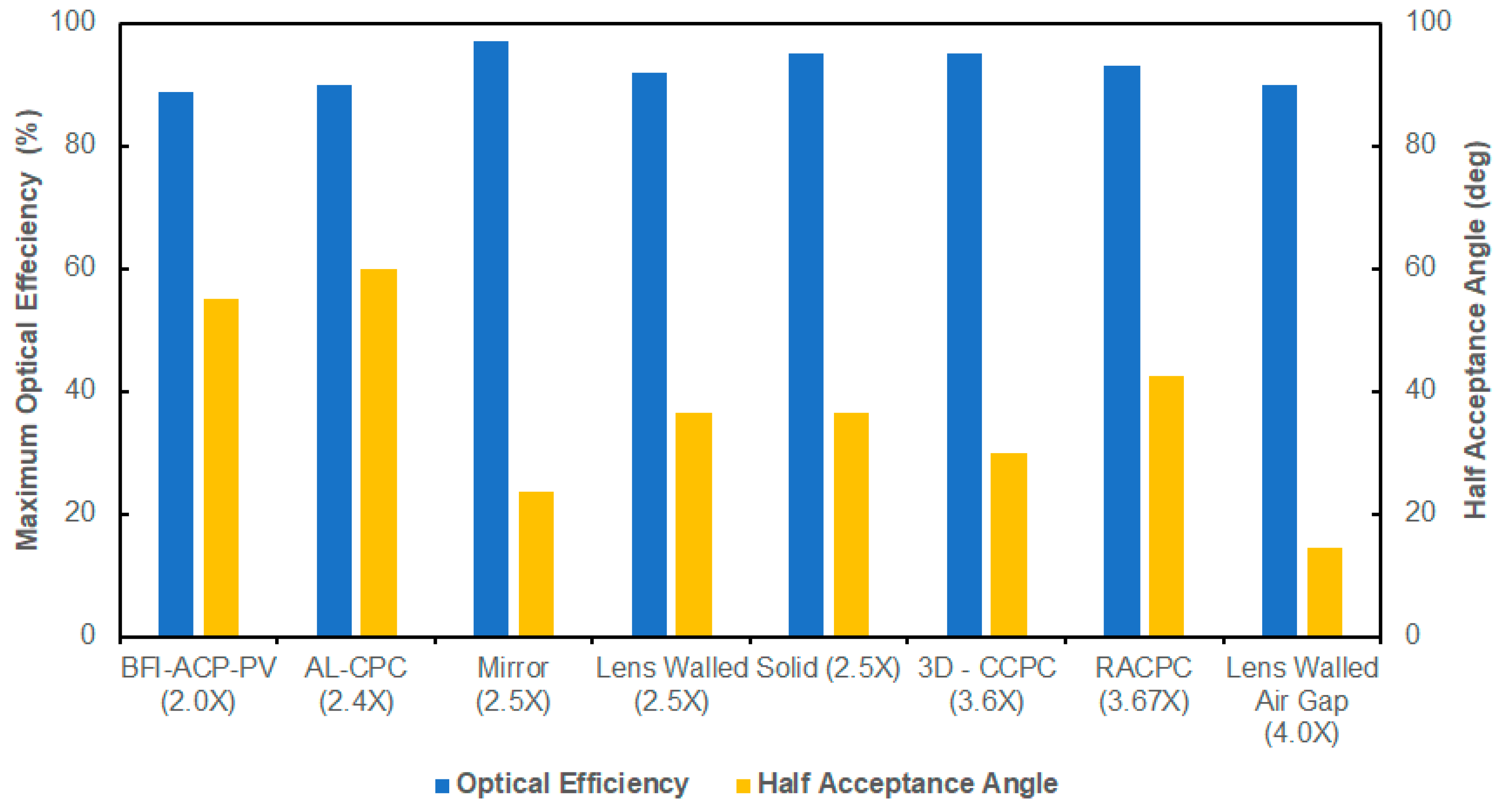
| Year | Author(s) | Type of CPC | Findings |
|---|---|---|---|
| 2012 | Su et al. [62] | 2-D Lens walled CPC | Looking at the monthly accumulated solar energy collection, the lens-walled CPC was able to achieve 20 to 30% larger than mirror CPC. |
| 2013 | Sellami and Mallick [74] | 3-D CCPC | The experimental results deviated from the simulation by 12%. During the experiment, the designed CCPC was able to concentrate the sunlight for 5 h with an optical efficiency of more than 80% providing an optical concentration of 2.88. |
| 2014 | Abu-Bakar et al. [57] | 3-D RACPC | The optical concentration gain increases as the height of the concentrator was increased, however, it showed a negative effect on the acceptance angle. The predicted annual power output from the system was about 220 kWh per year showing that the system increased the electricity output by 3.25 times. |
| 2014 | Li et al. [63] | Lens walled with air Gap (2-D) | It was observed that the fill factor of the mirror CPC dropped more drastically than lens-walled CPC with air gap after the incident angles were greater than 14.5°. The flux distribution in both the lens-walled and lens-walled with air gap showed improvement. |
| 2017 | Xuan et al. [64] | ALCPC | An asymmetric lens-walled CPC with a geometrical concentration ratio of 2.4 was tested. Maximum power output and short circuit current were 1.74 and 1.67 times higher than a bare cell respectively. |
| 2018 | Lu et al. [65] | BFI-ACP-PV | A building façade integrated asymmetric parabolic photovoltaic concentrator with a geometric concentration ratio of 2.0 and wide acceptance half angles of 0° and 55°. Electrical conversion that is higher by 5% and 10% at solar irradiance of 280 W/m2 and 670 W/m2 respectively compared to a system without PCM (phase change material). |
| 2019 | Tian et al. [73] | dCCPC | A dielectric CCPC with an inner, outer half-acceptance angles and refractive index of 14.47°, 22.02° and 1.49 respectively was tested. Total energy savings in buildings reached up to 13%, 10% and 5% in hot, continental and cold climates respectively. |
© 2019 by the authors. Licensee MDPI, Basel, Switzerland. This article is an open access article distributed under the terms and conditions of the Creative Commons Attribution (CC BY) license (http://creativecommons.org/licenses/by/4.0/).
Share and Cite
Alamoudi, A.; Saaduddin, S.M.; Munir, A.B.; Muhammad-Sukki, F.; Abu-Bakar, S.H.; Mohd Yasin, S.H.; Karim, R.; Bani, N.A.; Abubakar Mas’ud, A.; Ardila-Rey, J.A.; et al. Using Static Concentrator Technology to Achieve Global Energy Goal. Sustainability 2019, 11, 3056. https://0-doi-org.brum.beds.ac.uk/10.3390/su11113056
Alamoudi A, Saaduddin SM, Munir AB, Muhammad-Sukki F, Abu-Bakar SH, Mohd Yasin SH, Karim R, Bani NA, Abubakar Mas’ud A, Ardila-Rey JA, et al. Using Static Concentrator Technology to Achieve Global Energy Goal. Sustainability. 2019; 11(11):3056. https://0-doi-org.brum.beds.ac.uk/10.3390/su11113056
Chicago/Turabian StyleAlamoudi, Abdullah, Syed Muhammad Saaduddin, Abu Bakar Munir, Firdaus Muhammad-Sukki, Siti Hawa Abu-Bakar, Siti Hajar Mohd Yasin, Ridoan Karim, Nurul Aini Bani, Abdullahi Abubakar Mas’ud, Jorge Alfredo Ardila-Rey, and et al. 2019. "Using Static Concentrator Technology to Achieve Global Energy Goal" Sustainability 11, no. 11: 3056. https://0-doi-org.brum.beds.ac.uk/10.3390/su11113056