Semi-Dry Carbonation Process Using Fly Ash from Solid Refused Fuel Power Plant

Energy & Environmental Division, Korea Institute of Ceramic Engineering & Technology (KICET), 101 Soho-ro, Jinju-si, Gyeongsangnam-do 52581, Korea
*
Author to whom correspondence should be addressed.
Sustainability 2019, 11(3), 908; https://0-doi-org.brum.beds.ac.uk/10.3390/su11030908
Submission received: 22 January 2019
/
Revised: 4 February 2019
/
Accepted: 8 February 2019
/
Published: 11 February 2019
(This article belongs to the Special Issue Emerging Technologies and Solutions for the Sustainable Climate Change Challenges)
Abstract
:The increasing CO2 concentration in the Earth’s atmosphere, mainly caused by fossil fuel combustion, has led to concerns about global warming. Carbonation is a technique that can be used as a carbon capture and storage (CCS) technology for CO2 sequestration. In this study, the utilization of the fly ash from a solid refused fuel (SRF) power plant as a solid sorbent material for CO2 capture via semi-dry carbonation reaction was evaluated as a simple process to reduce CO2. The fly ash was exposed to accelerated carbonation conditions at a relative humidity of 25, 50, 75, and 100%, to investigate the effects of humidity on the carbonation kinetics of the fly ash. The reaction conditions such as moisture, concentration of CO2, and reaction time can affect CO2 capture performance of fly ash. Due to a short diffusion length of H2CO3 in water, the semi-dry process exhibits faster carbonation reaction than the wet process. Especially, the semi-dry process does not require a wastewater treatment plant because it uses a small amount of water. This study may have important implications, illustrating the possibility of replacing the wet process with the semi-dry process.
1. Introduction
CO2 is a main greenhouse gas and undoubtedly a major contributor to global warming. Capturing CO2 from the atmosphere is an essential parameter of the carbon management for sequestrating CO2 from our environment. The concentration of CO2 in our atmosphere is promoted by the combustion of fossil fuels for generating electricity [1,2]. In addition, the amount of the fly ash produced from power plants is expected to increase continuously as the demand for electricity increases. Thus, the interest in fly ash utilization has increased [3,4,5,6].
Among many CO2 reduction and sequestration techniques, solid-looping using calcium oxide (CaO) is a promising CO2 capture process, known as carbonate looping [7,8,9,10,11,12,13]. This process is based on the reversible reaction between CaO and CO2 to form calcium carbonate. The carbonation reaction can be used to remove CO2 from the atmosphere. Derevschikov et al. prepared a CaO/Y2O3 sorbent to capture CO2 at high temperatures [14]. J. Shi et al. synthesized a CaO/sepiolite sorbent by the hydration reaction [15]. However, these manufacturing processes are complex and uneconomical for industrial application.
Meanwhile, solid refused fuel (SRF), a highly heterogeneous mixture of high calorific fraction of non-hazardous waste materials, has been recognized as a viable alternative to fossil fuels, and is already being used as a fuel in various industrial sectors, including power plants [16]. The fly ash from SRF plants contains about 20 wt% of lime (CaO) which can be used to sequester CO2 by aqueous carbonation. Thus, studies about utilizing fly ash as a solid sorbent material for CO2 capture have increased. In the carbonation reaction between CaO and CO2, water plays an essential role in hydrating the calcium-based materials to form calcium hydroxide and most studies were conducted in environments with a high amount of water. Loo et al. conducted accelerated wet carbonation experiments on circulating fluidized bed combustion (CFBC) ash (the prepared solution possessed an ash-to-water ratio of 1:10) [17]. Dananjayan et al. and Ebrahimi et al. conducted aqueous carbonation with the water-to-ash ratio of 15:1 with carbonation capacities of 50.3 g and 32 g of CO2/kg of fly ash, respectively [18,19].
However, although a Ca(OH)2 aqueous solution can be effectively used as an absorbent to capture CO2, commercialization of the CO2 capture process is still hindered because of the high amount of energy required to evaporate water. Moreover, the process needs a wastewater treatment plant which can be a source of greenhouse gasses.
In this study, we investigated the utilization of fly ash as a solid sorbent material for CO2 capture via semi-dry carbonation reaction. The effects of the amount of moisture, CO2 concentration, and reaction time on the performance of fly ash was investigated. The rest of the paper is structured as follows: Section 2 describes the experimental framework used to evaluate the semi-dry carbonation. Section 3 contains the composition changes after the carbonation of SRF ash. Section 4 and Section 5 present our discussions and conclusions.
2. Materials and Methods
2.1. Materials
Fly ash obtained from Korea District Heating Corporation in Korea was used for this research. The fly ash was dried in an oven at 100 °C for 10 h to remove moisture.
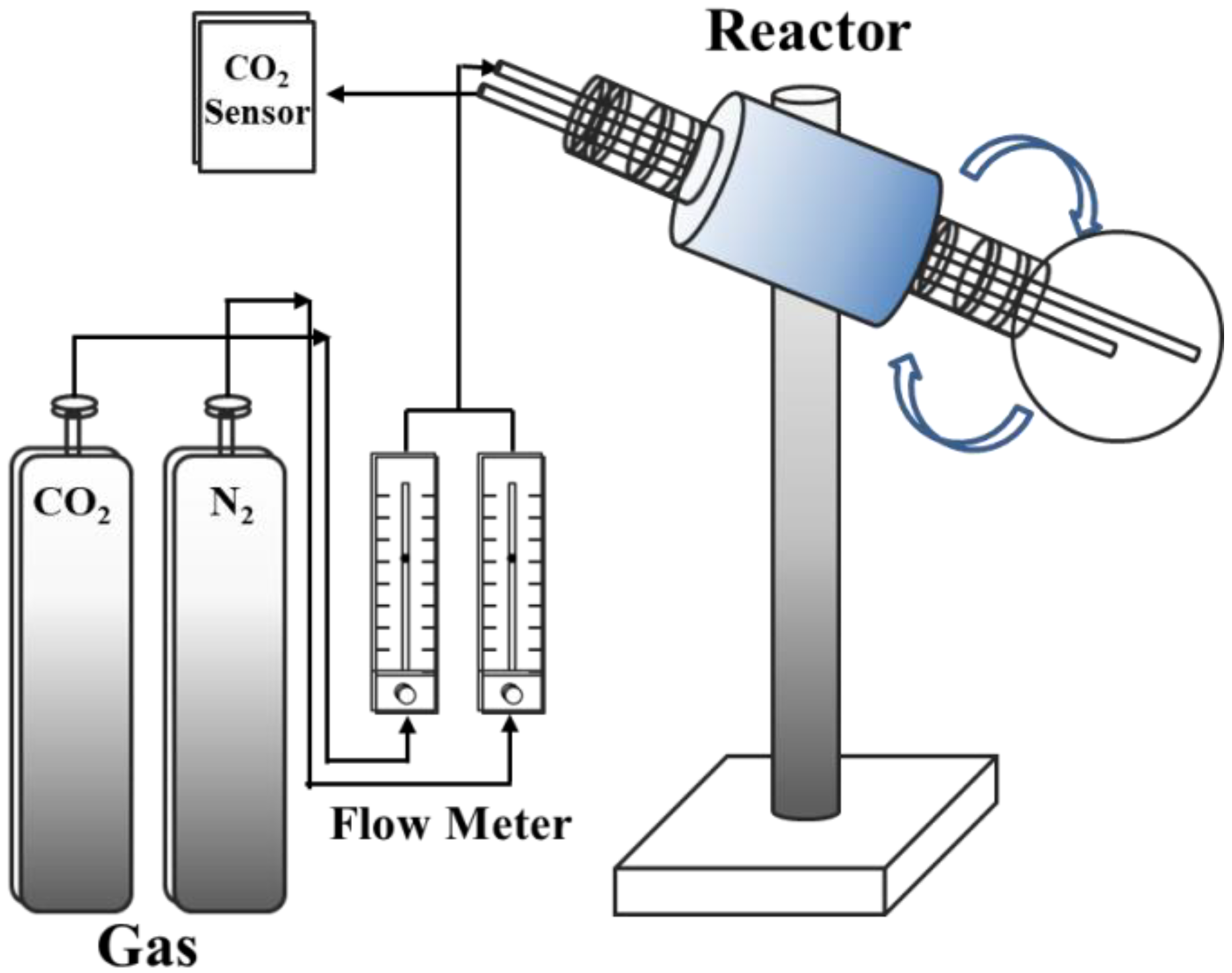
2.2. Semi-Dry Carbonation Reactor
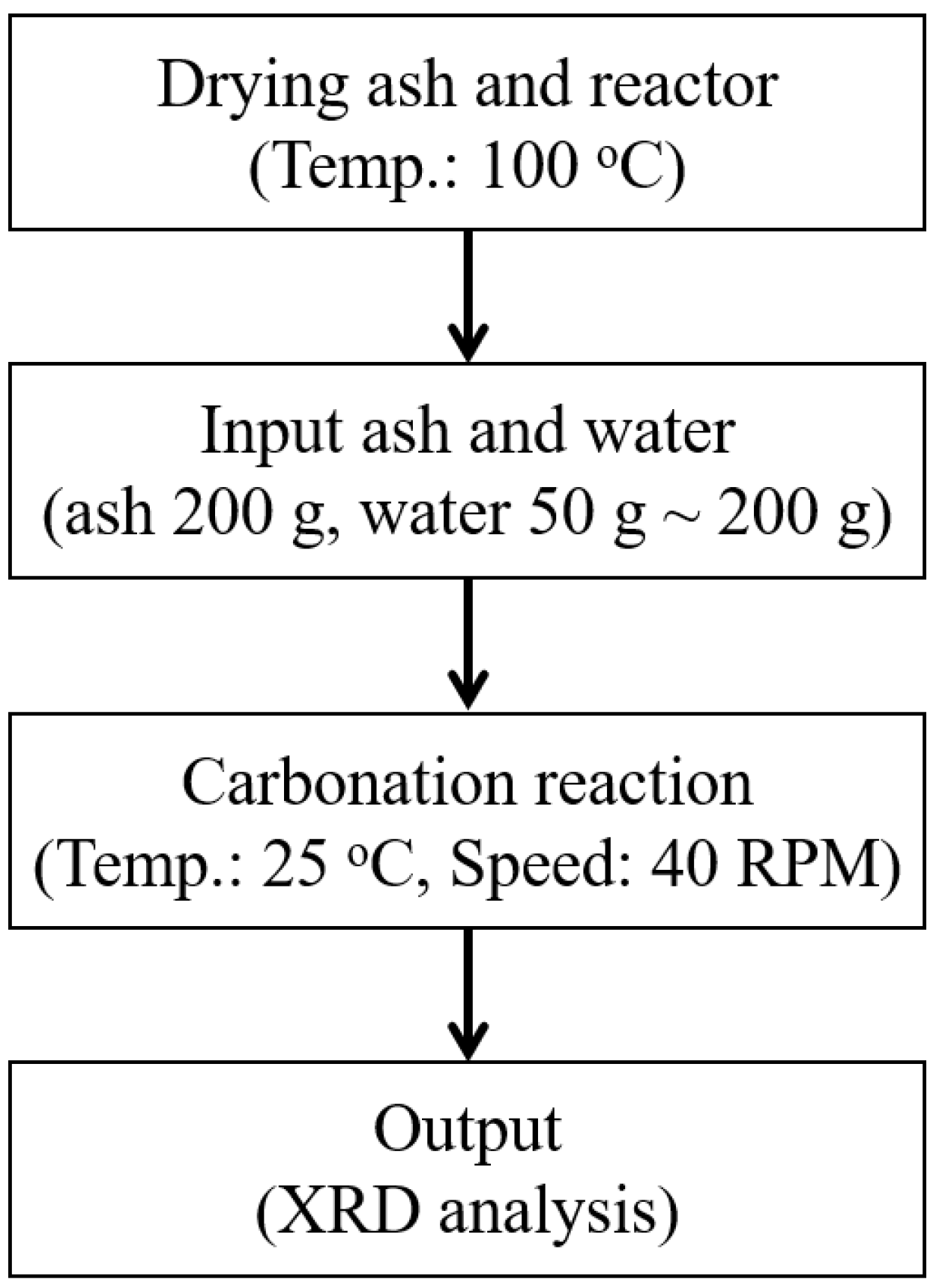
CO2 capture was conducted in a round-bottom flask with a single neck as shown in Figure 1. The mixture of fly ash (200 g) and water was delivered into the flask. The rotation speed of the flask was fixed at 40 RPM to shake the mixture. The CO2 stream (99.99%) and N2 stream (99.99%) were flowed into the reactor using the regulator and the flow meter to control the CO2 concentration. The total flow rate of the mixture gas was 10 L min−1. The temperature in the reactor was maintained at 25 °C. The flow chart of the experimental method of semi-dry carbonation is shown in Figure 2.
2.3. Characterizations
The morphologies and structures of the fly ash were analyzed by SEM (JSM-6700F, JEOL, Tokyo, Japan). The crystal structures were investigated by XRD (X’pert3 Powder, Malvern PANalytical) with Cu Ka radiation (λ = 1.5418 Å) at the Ssangyong Cement Co. (Daejeon). The particle size was measured using a laser diffraction particle size analyzer (PSA) (Mastersizer S Ver. 2.15, Malvern Instruments, Malvern, UK). The elemental compositions of the fly ash were investigated using X-ray fluorescence analysis (XRF, Primus2, Rigaku, Japan).
3. Results
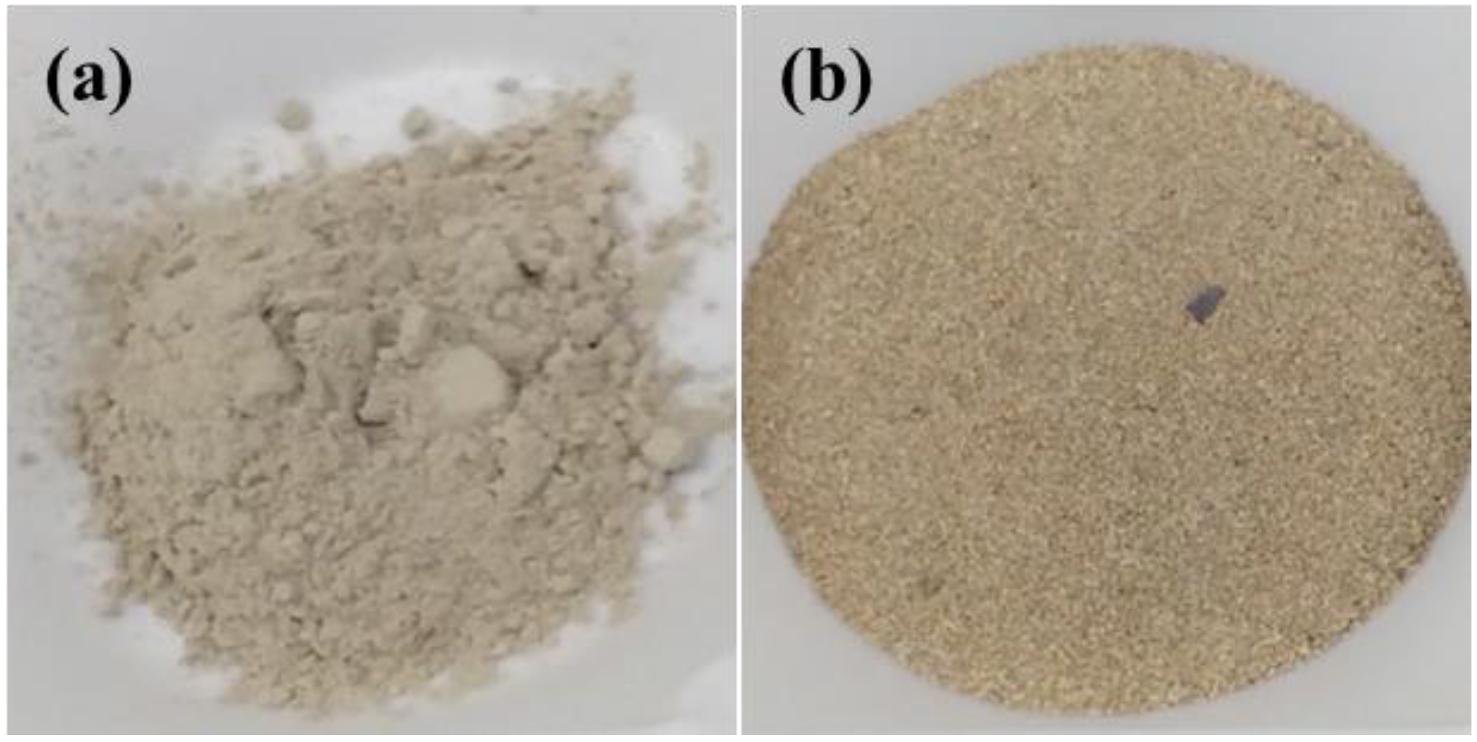
When SRF is burned in a bottom boiler, most of the unburned material is caught in the flue gas and captured as fly ash. Bottom ash is an incombustible byproduct that is collected from the bottom of the furnaces that burn SRF for generating steam. Therefore, fly ash and bottom ash are quite different physically and chemically. The fly ash and the bottom ash used in the study are shown in Figure 3.
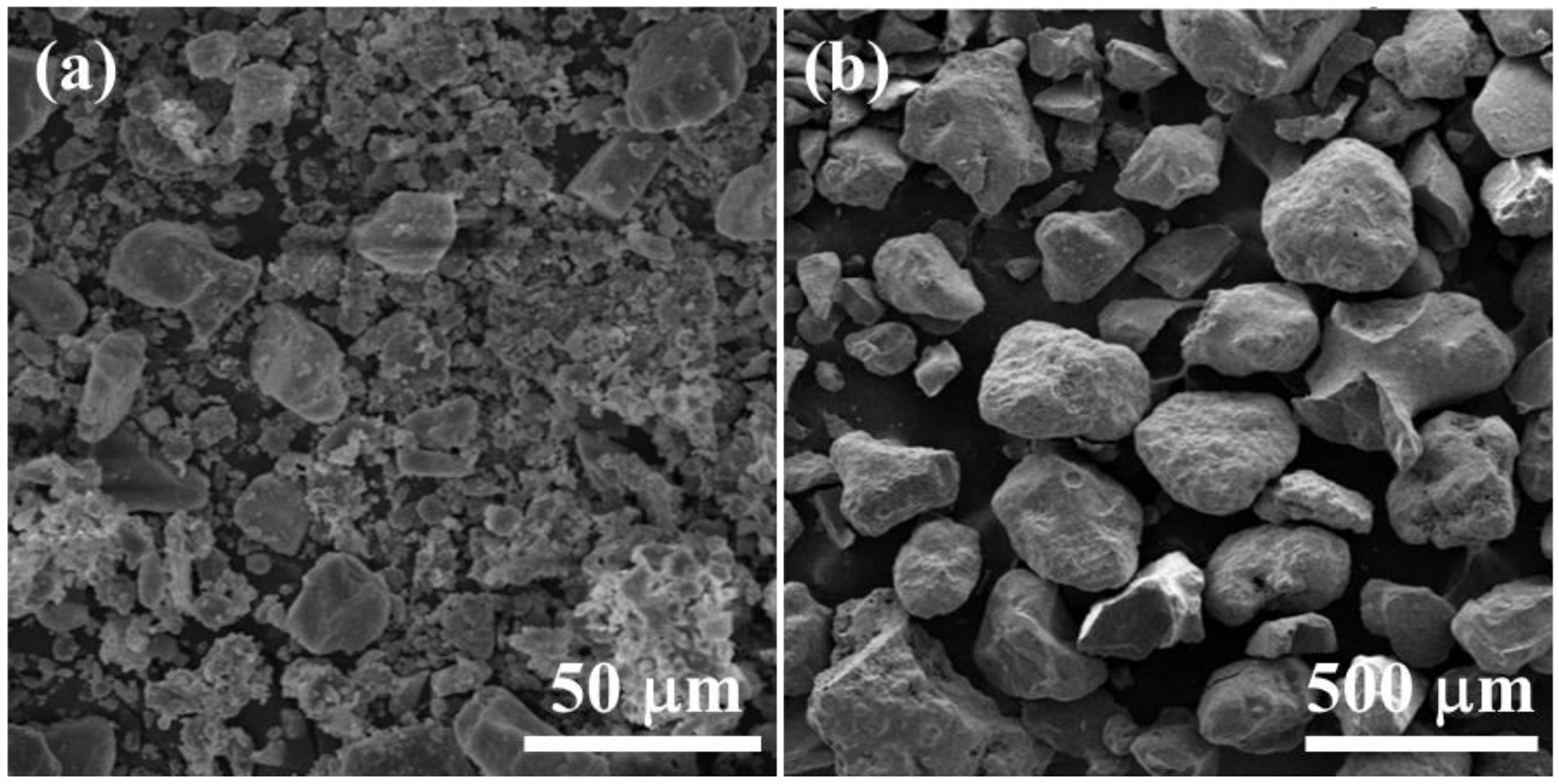
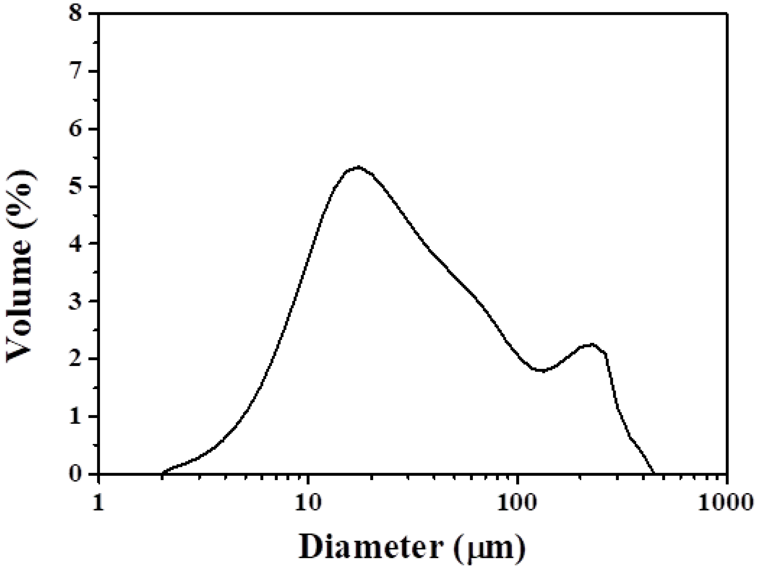
The fly ash was composed of fine particles, while the bottom ash was coarse and granular. The color of the bottom ash was dark, dull brown while the color of the fly ash was light brown. Figure 4 shows the morphologies of the fly ash and the bottom ash. The microstructure of the bottom ash (Figure 4b) had a much larger particle size compared to fly ash, which was about the size of sand but was more porous. As shown in Figure 5, the particle size of the fly ash was between 2 and 130 µm, with D50 (medium diameter) of 25 µm, D10 of 7 µm and D90 of 160 µm.
Table 1 shows the results of X-ray fluorescence analysis of the fly ash and bottom ash. Concentration of the major elements in the fly ash was given in the form of oxides by XRF. The chemical compositions of the fly ash showed that SiO2, Al2O3, Fe2O3, CaO, and Na2O were the main oxides. On the other hand, the major chemical composition of the bottom ash was SiO2. Lead and copper were the most common heavy metals in both ashes (Table 2).
The content of CaO (17.1%) in the fly ash was much higher than that in the bottom ash (7.27%). Therefore, the fly ash, which has high calcium-based contents, was selected for CO2 capture.
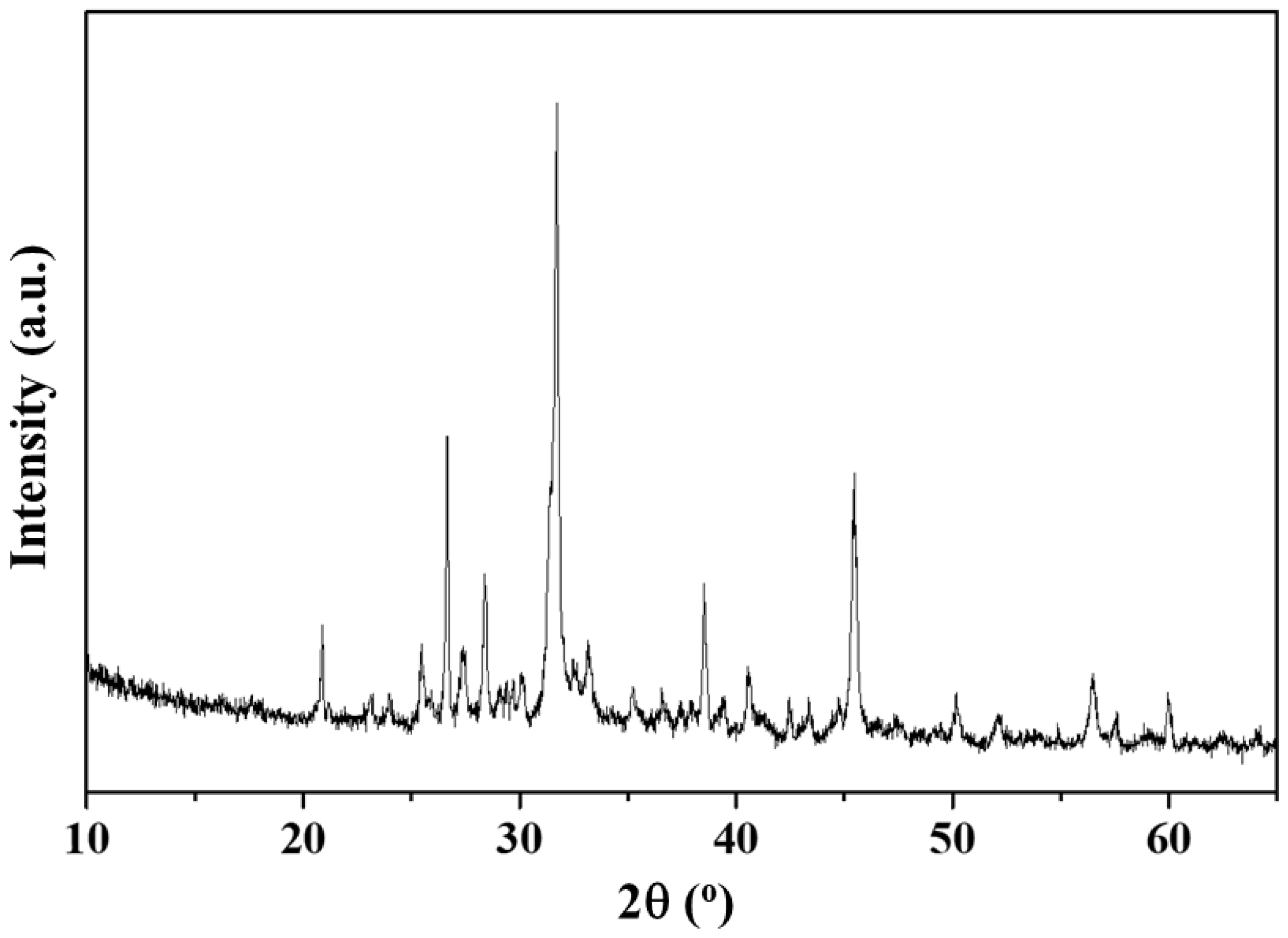
Figure 6 shows the crystal structure of the fly ash. The XRD pattern in Figure 6 confirms the formation of composite powders with mixed crystal structures consisting of periclase (MgO), lime (CaO), calcite (CaCO3), anhydrite (CaSO4), quartz (SiO2), mullite (3Al2O3-2SiO2), hematite (Fe2O3), gehlenite (Ca2Al[AlSiO7]), halite (NaCl), and sylvite (KCl). The calcium-based materials such as calcite, anhydrite, and gehlenite could be prepared by a high temperature combustion. By using the relative intensity ratio (RIR) technique from the XRD we found that the weight percentage of the periclase, lime, calcite, anhydrite, quartz, mullite, hematite, gehlenite, halite, and sylvite were 0.89, 0.40, 3.02, 7.57, 12.78, 0.54, 2.27, 24.58, 42.46, and 5.48%, respectively (Table 3).
Among the above materials, calcium-based materials (lime, anhydrite, and gehlenite) can react with CO2:
Gehlenite [21]:
4Ca2Al(AlSiO7) + 18H2O → CaAl2Si4O12·2H2O + 7Ca(OH)2 + 6Al(OH)3
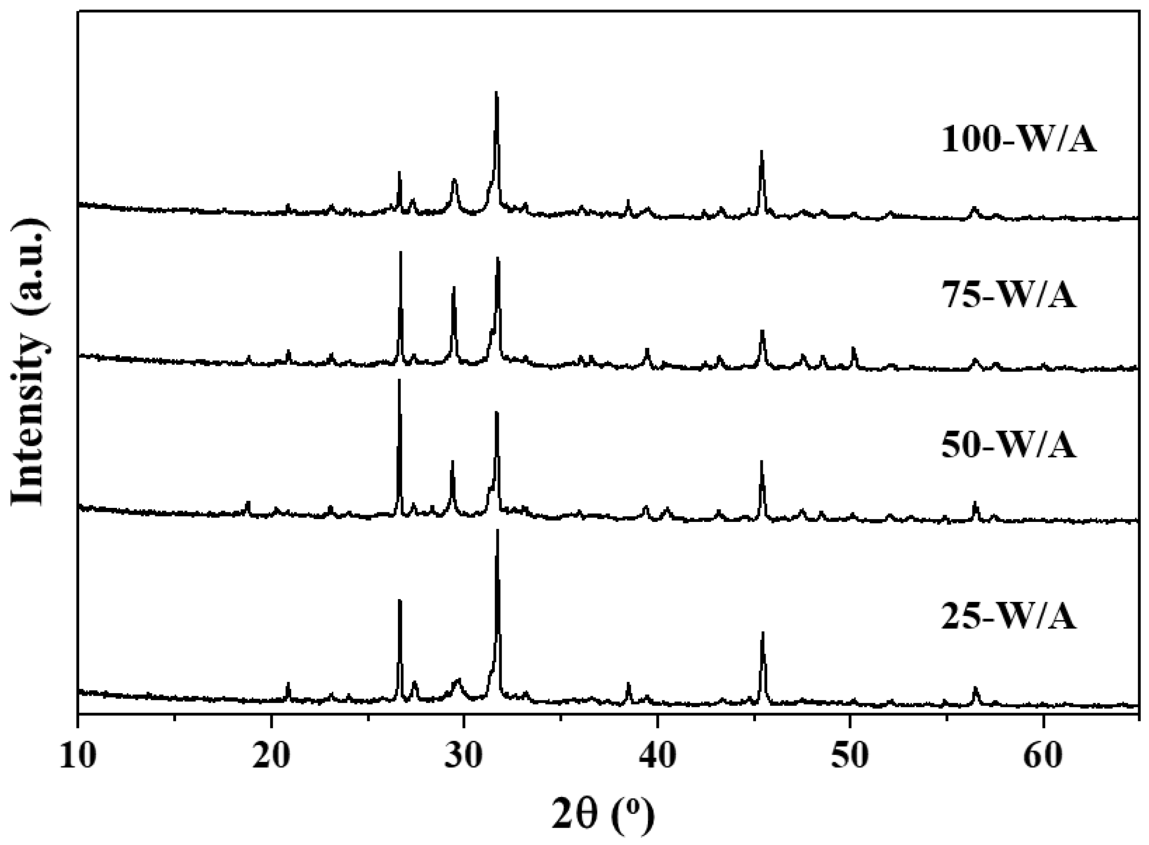
To investigate the effect of the amount of moisture on the performance of fly ash for CO2 capture, reaction with CO2 was conducted with the following amounts of water: 25 (25-W/A), 50 (50-W/A), 75 (75-W/A), and 100% (100-W/A). The CO2 concentration and reaction time were fixed at 100% and 60 min, respectively.
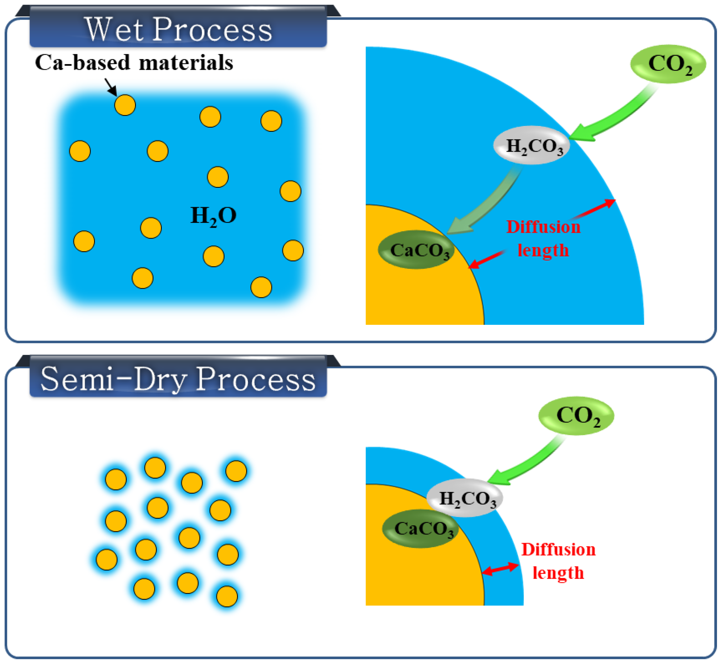
Figure 7 and Table 4 show the crystal structure of the fly ash after CO2 capture using different amounts of moisture and materials by using the relative intensity ratio (RIR) technique from the XRD. The CaCO3 components of the 25-W/A, 50-W/A, 75-W/A, and 100-W/A were 14.13, 21.31, 26.16, and 21.98%, respectively. The amount of CaCO3 increased with increasing the amount of water. This suggests that the presence of water played an essential role in hydrating the calcium-based materials to form calcium hydroxide, which then sequestrated carbon by forming calcium carbonate. Notably, the amount of CaCO3 increased from 3.02 to 26.16% when the ratio of the ash-to-water was 1:0.75. The results showed that fly ash of 100 g from a SRF fired power plant captured CO2 of 10.17 g. However, when the ratio of the ash-to-water was 1:1, the amount of CaCO3 decreased. CO2 in gaseous phase does not react with calcium-based materials; it has to dissolve in the water first to form carbonic acid (H2CO3) [22]. As shown in Figure 8, the diffusion length of the H2CO3 from the outside of the water to the calcium-based materials increased with the increasing amount of water. Therefore, the fly ash with too much water reacted slowly with CO2.
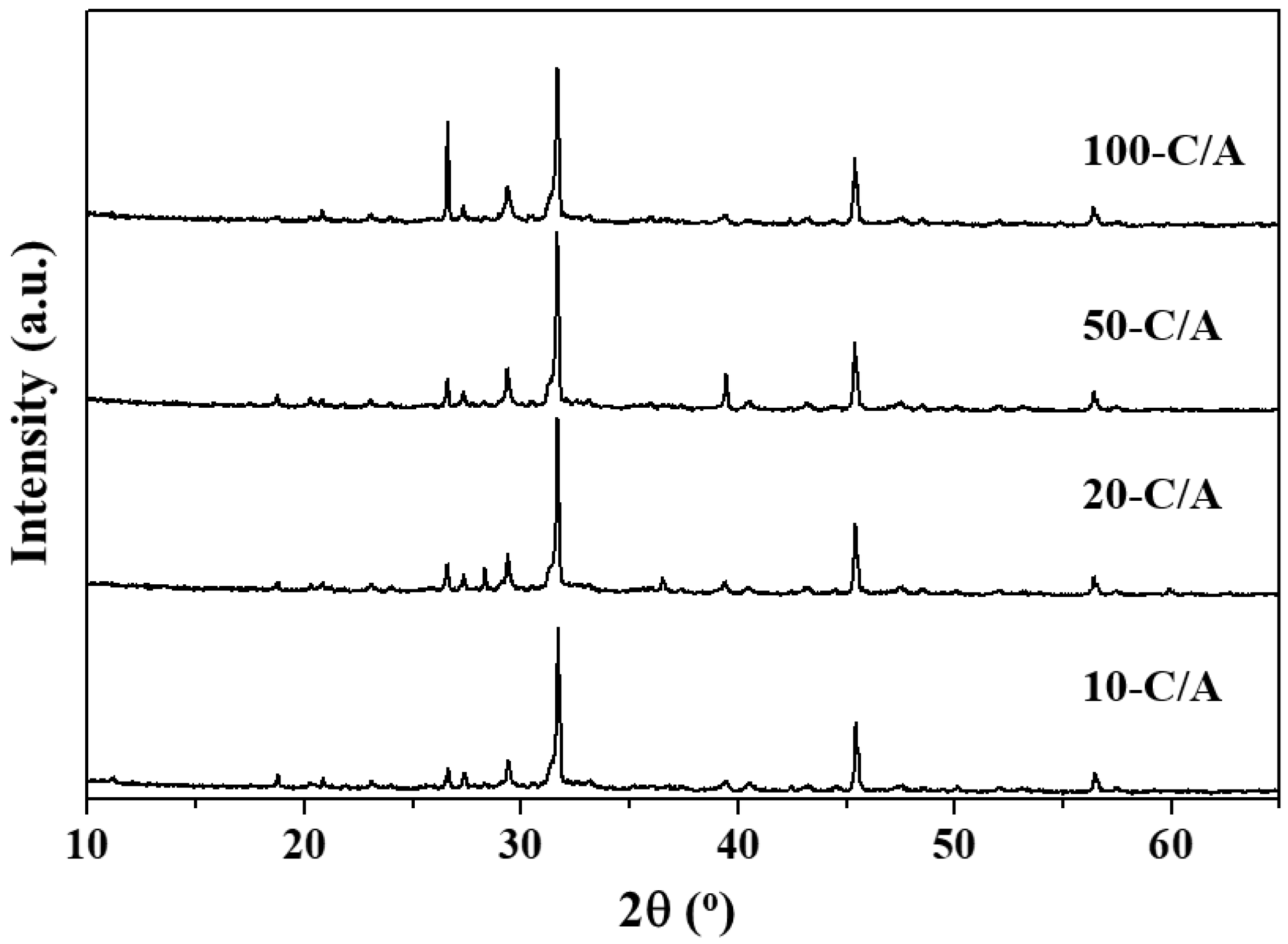
To investigate the properties of the fly ash with a small amount of water in the environments with low CO2 concentrations, CO2 captures were conducted at CO2 concentrations of 10 (10-C/A), 20 (20-C/A), 50 (50-C/A), and 100% (100-C/A). The moisture content and reaction time were fixed at 20% and 10 min, respectively.
Figure 9 and Table 5 show the crystal structure of the fly ash after CO2 capture using different concentrations of CO2 and the amount of materials by using the relative intensity ratio (RIR) technique from the XRD. The CaCO3 components of the 10-C/A, 20-C/A, 50-C/A, and 100-C/A were 15.21, 19.46, 19.86, and 21.98%, respectively. As shown in Table 5, the CaCO3 component stabilized at CO2 concentration of 20%. This result indicates that the semi-dry process can be applied to the power plant without a CO2 concentration process.
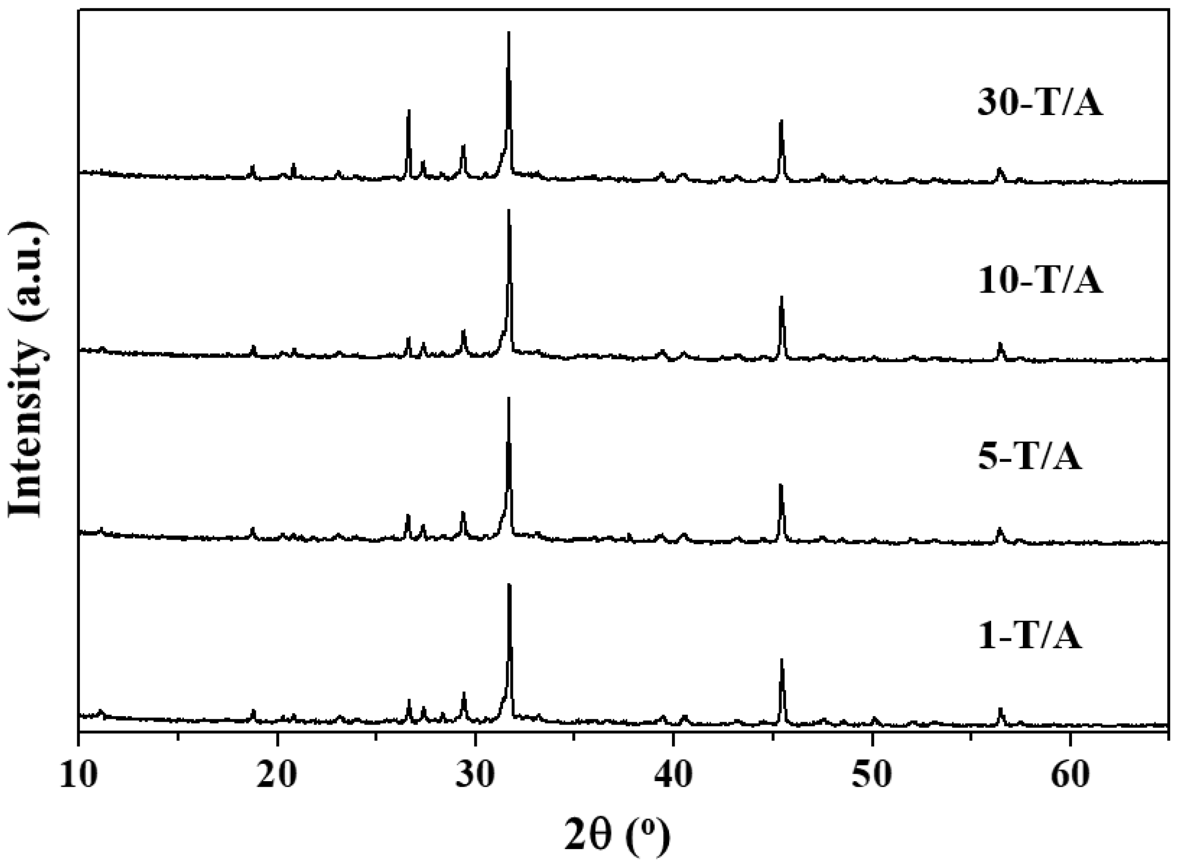
Figure 10 and Table 6 show the crystal structure of the fly ash after CO2 capture in a reaction time of 1 (1-T/A), 5 (5-T/A), 10 (10-T/A), and 30 min (30-T/A), and the amount of materials. The CaCO3 component of the 1-T/A, 5-T/A, 10-T/A, and 30-T/A was 16.26, 15.16, 15.21, and 16.72%, respectively. As shown in Table 6, the carbonation performed well despite the short reaction time of 1 minute. This result indicates that the semi-dry process can be designed as a continuous process to capture large scales of CO2.
4. Discussions
The utilization of SRF ash has emerged as one of the most important interventions in SRF power plants. Due to the calcium-based materials in the SRF ash, the SRF ash can be reused as a material for CO2 capture. According to Loo et al., who studied the utilization of circulating fluidized bed combustion (CFBC) ash, high humidity conditions during the carbonation process were a critical factor that significantly enhanced the CO2 uptake in the CFBC ash [17]. However, in this study, the results show that the high amount of water led to a low efficiency of carbonation reaction. This may be due to the fact that the diffusion length of the H2CO3 increased correlatively with the amount of water. These results demonstrate that the semi-dry carbonation process is more effective in the aspect of cost and time compared to the wet process. The carbonated SRF ash can be used in various construction industries such as a mineral admixture for concrete [23]. For the utilization of the carbonated SRF ash prepared via semi-dry carbonation process, further research should be conducted on controlling the conditions of the process such as temperature and pH value.
5. Conclusions
In this study, the utilization of the fly ash from SRF power plant as a solid sorbent material for CO2 capture via semi-dry carbonation reaction was evaluated as a simple CO2 reduction technique which does not require a high cost wastewater treatment plant and an evaporating process. Quantitative analysis was conducted by using the relative intensity ratio technique from the XRD to study the potential for fly ash carbonation under semi-dry carbonation process. The amount of CO2 capture increased as the amount of water increased. However, when the ratio of the ash-to-water was 1:1, the amount of CO2 capture decreased because the diffusion length of the H2CO3, from the outside of the water to the calcium-based materials, increased with the increasing amount of water. The results indicated that H2O plays an important role in the carbonation of calcium-based materials. The fly ash of 100 g can capture 10.17 g of CO2 by semi-dry carbonation reaction without any treatment. The moisture content can affect the CO2 capture capacity but CO2 concentration and reaction time do not significantly affect the carbonation reaction. In the semi-dry carbonation process, the carbonation was well performed in the short reaction time and with low CO2 concentration. These results show that the semi-dry process can be designed as a continuous process and applied to a power plant directly without CO2 concentration processes.
Author Contributions
Conceived and wrote the manuscripts, J.H.K.; advice and revised the manuscript, W.T.K.; both authors agreed with the final version of manuscript.
Funding
National Research Foundation of Korea: 2017M3D8A2086035.
Acknowledgments
This research was supported by the National Strategic Project-Carbon Upcycling of the National Research Foundation of Korea (NRF) funded by the Ministry of Science and ICT (MSIT), the Ministry of Environment (ME) and the Ministry of Trade, Industry and Energy (MOTIE) (2017M3D8A2086035).
Conflicts of Interest
The authors declare no conflict of interest.
References
- Plaza, M.G.; Pevida, C.; Arenillas, A.; Rubiera, F.; Pis, J.J. CO2 capture by adsorption with nitrogen enriched carbons. Fuel 2007, 14, 2204–2212. [Google Scholar] [CrossRef]
- Yang, H.; Xu, Z.; Fan, M.; Gupta, R.; Slimane, R.B.; Bland, A.E.; Wright, I. Progress in carbon dioxide separation and capture: A review. J. Environ. Sci. 2008, 20, 14–27. [Google Scholar] [CrossRef]
- Al-Shawabkeh, A.; Matsuda, H.; Hasatani, M. Comparative reactivity of treated FBC- and PCC-fly ash for SO2 removal. Can. J. Chem. Eng. 1995, 15, 193–201. [Google Scholar]
- Davini, P. Flue gas treatment by activated carbon obtained from oil-fired fly ash. Carbon 2002, 40, 1973–1979. [Google Scholar] [CrossRef]
- Lu, G.Q.; Do, D.D. Adsorption properties of fly ash particles for NOx removal from flue gases. Fuel Process Technol. 1991, 27, 95–107. [Google Scholar] [CrossRef]
- Rubel, A.; Andrews, R.; Gonzalez, R.; Groppo, J.; Robl, T. Adsorption of Hg and NOx on coal by-products. Fuel 2005, 84, 911–916. [Google Scholar] [CrossRef]
- Florin, N.; Fennell, P. Synthetic CaO-based sorbent for CO2 capture. Energy Procedia 2011, 4, 830–838. [Google Scholar] [CrossRef]
- Han, S.-J.; Yoo, M.; Kim, D.-W.; Wee, J.-H. Carbon dioxide capture using calcium hydroxide aqueous solution as the absorbent. Energy Fuels 2011, 25, 3825–3834. [Google Scholar] [CrossRef]
- Manovic, V.; Anthony, E.J. Lime-based sorbents for high-temperature CO2 capture-a review of sorbent modification methods. Int. J. Environ. Res. Public Health 2010, 7, 3129–3140. [Google Scholar] [CrossRef] [PubMed]
- Zhang, H.; Liu, R.; Ning, T.; Lal, R. Higher CO2 absorption using a new class of calcium hydroxide (Ca(OH)2) nanoparticles. Environ. Chem. Lett. 2018, 16, 1095–1100. [Google Scholar] [CrossRef]
- Skoufa, Z.; Antzara, A.; Heracleous, E.; Lemonidou, A.A. Evaluating the activity and stability of CaO-based sorbents for post-combustion CO2 capture in fixed-bed reactor experiments. Energy Procedia 2016, 86, 171–180. [Google Scholar] [CrossRef]
- Ibrahim, A.-R.; Vuningoma, J.B.; Huang, Y.; Wang, H.; Li, J. Rapid carbonation for calcite from a solid-liquid-gas system with an imidazolium-based ionic liquid. Int. J. Mol. Sci. 2014, 15, 11350–11363. [Google Scholar] [CrossRef] [PubMed]
- Solieman, A.A.A.; Dijkstra, J.W.; Haije, W.G.; Cobden, P.D.; van den Brink, R.W. Calcium oxide for CO2 capture: Operational window and efficiency penalty in sorption-enhanced steam methane reforming. Int. J. Greenh. Gas Control 2009, 3, 393–400. [Google Scholar] [CrossRef]
- Derevschikov, V.S.; Lysikov, A.L.; Okunev, A.G. CaO/Y2O3 pellets for reversible CO2 capture in sorption enhanced reforming process. Catal. Sustain. Energy 2012, 1, 53–59. [Google Scholar] [CrossRef]
- Shi, J.; Li, Y.; Zhang, Q.; Ma, X.; Duan, L.; Zhou, X. CO2 capture performance of a novel synthetic CaO/sepiolite sorbent at calcium looping conditions. Appl. Energy 2017, 203, 412–421. [Google Scholar] [CrossRef]
- Garg, A.; Smith, R.; Hill, D.; Simms, N.; Pollard, S. Wastes as co-fuels: The policy framework for solid recovered fuel (SRF) in Europe, with UK implications. Environ. Sci. Technol. 2007, 41, 4868–4874. [Google Scholar] [CrossRef] [PubMed]
- Loo, L.; Maaten, B.; Konist, A.; Siirde, A.; Neshumayev, D.; Pihu, T. Carbon dioxide emission factors for oxy-fuel CFBC and aqueous carbonation of the Ca-rich oil shale ash. Energy Procedia 2017, 128, 144–149. [Google Scholar] [CrossRef]
- Dananjayan, R.R.T.; Kandasamy, P.; Andimuthu, R. Direct mineral carbonation of coal fly ash for CO2 sequestration. J. Clean. Prod. 2016, 112, 4173–4182. [Google Scholar] [CrossRef]
- Ebrahimi, A.; Saffari, M.; Milani, D.; Montoya, A.; Valix, M.; Abbas, A. Sustainable transformation of fly ash industrial waste into a construction cement blend via CO2 carbonation. J. Clean. Prod. 2017, 156, 660–669. [Google Scholar] [CrossRef]
- Wang, C.; Jia, L.; Tan, Y.; Anthony, E.J. Carbonation of fly ash in oxy-fuel CFB combustion. Fuel 2008, 87, 1108–1114. [Google Scholar] [CrossRef]
- Hoschek, G. Gehlenite stability in the system CaO-Al2O3-SiO2-H2O-CO2. Contrib. Mineral. Petrol. 1974, 47, 245–254. [Google Scholar] [CrossRef]
- Chun, Y.M.; Naik, T.R.; Kraus, R.N. Carbon dioxide sequestration in concrete in different curing environments. In Proceedings of the Conference on Sustainable Construction Materials and Technologies, Coventry, UK, 11–13 June 2007; pp. 18–24. [Google Scholar]
- Siriruang, C.; Toochinda, P.; Julnipitawong, P. CO2 capture using fly ash from coal fired power plant and applications of CO2-captured fly ash as a mineral admixture for concrete. J. Environ. Manag. 2016, 170, 70–78. [Google Scholar] [CrossRef] [PubMed]
Figure 1.
Schematic diagram of the semi-dry carbonation system for the CO2 capture.

Figure 2.
Experimental method of semi-dry carbonation.

Figure 3.
Photographs of (a) fly ash and (b) bottom ash.

Figure 4.
Morphologies of the (a) fly ash and (b) bottom ash.

Figure 5.
Particle size distribution of fly ash.

Figure 6.
X-ray diffraction pattern of fly ash.

Figure 7.
X-ray diffraction patterns of fly ashes after carbonation with various amount of water.

Figure 8.
Schematic diagram of the semi-dry process and wet process for the CO2 capture.

Figure 9.
X-ray diffraction patterns of fly ashes after carbonation with various CO2 concentrations.
Figure 9.
X-ray diffraction patterns of fly ashes after carbonation with various CO2 concentrations.

Figure 10.
X-ray diffraction patterns of fly ashes after carbonation with various reaction times.


Table 1.
Oxide compositions in fly ash and bottom ash (wt%).
| SiO2 | Al2O3 | Fe2O3 | CaO | MgO | N2O | K2O | SO3 | P2O5 | Cl | |
|---|---|---|---|---|---|---|---|---|---|---|
| Fly Ash | 24.9 | 13.2 | 2.56 | 17.1 | 1.82 | 13.1 | 2.36 | 1.29 | 2.96 | 12.8 |
| Bottom Ash | 85.0 | 2.90 | 0.87 | 7.27 | 0.50 | 1.01 | 0.35 | 0.18 | 0.94 | 0.2 |
Table 2.
Heavy metals in fly ash and bottom ash (mg kg−1).
| Pb | Cd | As | Hg | Cu | |
|---|---|---|---|---|---|
| Fly Ash | 785 | 33 | N.D. | N.D. | 5620 |
| Bottom Ash | 74 | N.D. | N.D. | N.D. | 2240 |
Table 3.
Quantitative analytical results obtained by relative intensity ratio (RIR) method (wt%) of the fly ash.
Table 3.
Quantitative analytical results obtained by relative intensity ratio (RIR) method (wt%) of the fly ash.
| Periclase | Lime | Calcite | Anhydrite | Quartz | Mullite | Hematite | Gehlenite | Halite | Sylvite |
|---|---|---|---|---|---|---|---|---|---|
| 0.89 | 0.40 | 3.02 | 7.57 | 12.78 | 0.54 | 2.27 | 24.58 | 42.46 | 5.48 |
Table 4.
Quantitative analytical results obtained by RIR method (wt%) of the fly ash after carbonation with various amounts of water.
Table 4.
Quantitative analytical results obtained by RIR method (wt%) of the fly ash after carbonation with various amounts of water.
| Samples | Periclase | Lime | Calcite | Anhydrite | Quartz | Mullite | Hematite | Gehlenite | Halite | Sylvite |
|---|---|---|---|---|---|---|---|---|---|---|
| 25-W/A | 0.35 | 0.00 | 14.13 | 1.68 | 18.07 | 0.28 | 2.14 | 22.50 | 40.79 | 0.06 |
| 50-W/A | 0.88 | 0.14 | 21.31 | 1.92 | 18.91 | 0.65 | 3.66 | 23.03 | 26.03 | 3.21 |
| 75-W/A | 0.58 | 0.06 | 26.16 | 2.12 | 17.34 | 0.72 | 3.31 | 23.25 | 25.15 | 1.30 |
| 100-W/A | 0.95 | 0.24 | 21.98 | 2.25 | 9.32 | 2.47 | 0.82 | 24.01 | 37.96 | 0.00 |
Table 5.
Quantitative analytical results obtained by RIR method (wt%) of the fly ash after carbonation with various CO2 concentrations.
Table 5.
Quantitative analytical results obtained by RIR method (wt%) of the fly ash after carbonation with various CO2 concentrations.
| Samples | Periclase | Lime | Calcite | Anhydrite | Quartz | Mullite | Hematite | Gehlenite | Halite | Sylvite |
|---|---|---|---|---|---|---|---|---|---|---|
| 10-C/A | 0.34 | 0.00 | 15.21 | 1.56 | 14.32 | 1.09 | 1.22 | 25.11 | 40.79 | 0.06 |
| 20-C/A | 0.34 | 0.02 | 19.46 | 1.33 | 11.35 | 0.84 | 1.39 | 24.39 | 38.34 | 2.54 |
| 50-C/A | 0.38 | 0.01 | 19.86 | 1.12 | 14.84 | 0.33 | 0.91 | 22.55 | 38.72 | 1.17 |
| 100-C/A | 0.95 | 0.24 | 21.98 | 2.25 | 13.17 | 2.47 | 0.82 | 24.01 | 37.96 | 0.00 |
Table 6.
Quantitative analytical results obtained by RIR method (wt%) of the fly ash after carbonation with various reaction times.
Table 6.
Quantitative analytical results obtained by RIR method (wt%) of the fly ash after carbonation with various reaction times.
| Samples | Periclase | Lime | Calcite | Anhydrite | Quartz | Mullite | Hematite | Gehlenite | Halite | Sylvite |
|---|---|---|---|---|---|---|---|---|---|---|
| 10-C/A | 0.34 | 0.00 | 15.21 | 1.56 | 14.32 | 1.09 | 1.22 | 25.11 | 40.79 | 0.06 |
| 20-C/A | 0.34 | 0.02 | 19.46 | 1.33 | 11.35 | 0.84 | 1.39 | 24.39 | 38.34 | 2.54 |
| 50-C/A | 0.38 | 0.01 | 19.86 | 1.12 | 14.84 | 0.33 | 0.91 | 22.55 | 38.72 | 1.17 |
| 100-C/A | 0.95 | 0.24 | 21.98 | 2.25 | 13.17 | 2.47 | 0.82 | 24.01 | 37.96 | 0.00 |
© 2019 by the authors. Licensee MDPI, Basel, Switzerland. This article is an open access article distributed under the terms and conditions of the Creative Commons Attribution (CC BY) license (http://creativecommons.org/licenses/by/4.0/).
Share and Cite
MDPI and ACS Style
Kim, J.H.; Kwon, W.T. Semi-Dry Carbonation Process Using Fly Ash from Solid Refused Fuel Power Plant. Sustainability 2019, 11, 908. https://0-doi-org.brum.beds.ac.uk/10.3390/su11030908
AMA Style
Kim JH, Kwon WT. Semi-Dry Carbonation Process Using Fly Ash from Solid Refused Fuel Power Plant. Sustainability. 2019; 11(3):908. https://0-doi-org.brum.beds.ac.uk/10.3390/su11030908
Chicago/Turabian StyleKim, Jung Hyun, and Woo Teck Kwon. 2019. "Semi-Dry Carbonation Process Using Fly Ash from Solid Refused Fuel Power Plant" Sustainability 11, no. 3: 908. https://0-doi-org.brum.beds.ac.uk/10.3390/su11030908
Note that from the first issue of 2016, this journal uses article numbers instead of page numbers. See further details here.