A New Robust Energy Management and Control Strategy for a Hybrid Microgrid System Based on Green Energy


1
Electrical Engineering Department, University of Basrah, Basrah 61001, Iraq
2
Civil Engineering Department, Hydraulics, Energy and Environment, Universidad Politécnica de Madrid (UPM), CP 28040 Madrid, Spain
*
Author to whom correspondence should be addressed.
Sustainability 2020, 12(14), 5724; https://0-doi-org.brum.beds.ac.uk/10.3390/su12145724
Submission received: 18 June 2020
/
Revised: 11 July 2020
/
Accepted: 14 July 2020
/
Published: 16 July 2020
(This article belongs to the Special Issue Renewable Energies for Sustainable Development)
Abstract
:The recent few years have seen renewable energy becoming immensely popular. Renewable energy generation capacity has risen in both standalone and grid-connected systems. The chief reason is the ability to produce clean energy, which is both environmentally friendly and cost effective. This paper presents a new control algorithm along with a flexible energy management system to minimize the cost of operating a hybrid microgrid. The microgrid comprises fuel cells, photovoltaic cells, super capacitors, and other energy storage systems. There are three stages in the control system: an energy management system, supervisory control, and local control. The energy management system allows the control system to create an optimal day-ahead power flow schedule between the hybrid microgrid components, loads, batteries, and the electrical grid by using inputs from economic analysis. The discrepancy between the scheduled power and the real power delivered by the hybrid microgrid is adjusted for by the supervisory control stage. Additionally, this paper provides a design for the local control system to manage local power, DC voltage, and current in the hybrid microgrid. The operation strategy of energy storage systems is proposed to solve the power changes from photovoltaics and houses load fluctuations locally, instead of reflecting those disturbances to the utility grid. Furthermore, the energy storage systems energy management scheme will help to achieve the peak reduction of the houses’ daily electrical load demand. Also, the control of the studied hybrid microgrid is designed as a method to improve hybrid microgrid resilience and incorporate renewable power generation and storage into the grid. The simulation results verified the effectiveness and feasibility of the introduced strategy and the capability of proposed controller for a hybrid microgrid operating in different modes. The results showed that (1) energy management and energy interchange were effective and contributed to cost reductions, CO2 mitigation, and reduction of primary energy consumption, and (2) the newly developed energy management system proved to provide more robust and high performance control than conventional energy management systems. Also, the results demonstrate the effectiveness of the proposed robust model for microgrid energy management.
1. Introduction
During the previous decade, distributed energy systems have assumed supreme importance in the electrical power infrastructure because they lead to a reduction in greenhouse gas emissions and produce quality power with increased efficiency and service reliability. Deploying distributed energy resources facilitates a modification in the way energy is transmitted through the electrical power grid and provides flexibility to the consumer concerning energy use.
To accomplish an adequately set up distributed energy ecosystem, there is a necessity to convert the power system into smaller distributed-energy systems [1]. These distributed systems may incorporate several power sources like photovoltaic systems, wind turbines, or fuel cells. These fuel-cell-based energy sources are essential since power generation based on such a system may be set up near or at the consumer premises. Recent research [2] indicates that such resources help decrease household emissions, operating costs, and primary energy required to produce electricity [3].
The integration of various distributed energy resources, distributed loads, and energy storage systems with a renewable energy ecosystem is called a microgrid [4]. In the recent past, microgrids have been explored with immense interest as power systems that offer resilience and help set up a smart active electrical grid. Additionally, it has the potential to enhance system safety, reliability, efficiency, and boost connectivity with renewable energy sources [5]. The microgrid may not be connected to the utility grid since it can be used as a standalone system supplying energy to controllable loads using several distributed energy sources. The introduction of controllable loads and distributed energy systems causes several challenges for energy management systems. The primary role of an energy management system is to calculate the adequate energy transmission from the microgrid and the primary energy network independently and meet load requirements on an hourly basis. The literature contains several proposals regarding microgrid energy management systems using varying algorithms and different microgrids [6]. The rest of this paper is organized as follows. Section 2 presents a description of the related works. Section 3 presents a description of the proposed system described in this paper. Section 4 presents the mathematical model of the distributed hybrid generation system, Section 5 presents the control methods for photovoltaics and fuel cell system, Section 6 presents the supervisory control method of the proposed system. Section 7 presents the energy management systems for houses and Section 8 presents the results of the proposed system. Finally, Section 9 concludes the paper.
2. Related Work
This section contains a review of the pertinent research regarding energy management strategies related to the topics connected to this work. In Lujano-Rojas et al. [7], the photovoltaic system with battery backup is operated in the grid-connected and islanded modes of operation. In this paper, separate control algorithms are implemented for the inverter, battery, and photovoltaic array for maximum utilization of available sources for meeting the energy requirement of the consumer. In Delgado and Navarro [8], the authors propose a linear programming-based algorithm to manage microgrid power. This algorithm facilitates adequate generator use for controllable and uncontrollable electrical loads. One example of an optimization challenge is the adequate use of diesel generators while maintaining operational and economic limitations due to energy demand and supply for each microgrid component (storage system, load, and generator). In the study conducted by Helal et al. [9], the power management system for an AC/DC hybrid microgrid was explored in an isolated area that uses a photovoltaic setup for desalination. The optimization algorithm suggested uses mixed-integer nonlinear programming, and the objective function works towards reducing the daily operational cost. In Correa et al. [10], the authors formulated a virtual power plant (VPP)-based power management system. The microgrid investigated consists of a solar panel and an energy storage system working in tandem. Linear programming methods are used to design the techniques required to decrease operating expenditure. Renewable energy is accounted for in the energy models like the one in Colombia and is typically based on hydropower resources. In Dufo and Agustín [11], the authors present a generic algorithm-based control system to optimally manage energy in a hybrid system. The system comprises renewable energy sources such as hydropower, wind turbines, and photovoltaics in conjunction with AC generators, fuel cells, and an electrolyzer. Energy management optimization leads to decreased operating costs. This facilitates the surplus produced by the renewable source to be stored in batteries and use of the electrolyzer to produce hydrogen gas. Loads that cannot be powered using a renewable energy source may be operated using a fuel cell, or by using energy from the batteries. In Das et al. [12], the authors investigate the impact of supplementing a standalone hybrid microgrid based on photoelectric sources with gas turbines and an internal combustion engine. This multi-objective generic technique was implemented to achieve a system optimized considering energy cost and efficiency. Load evaluation was conducted using thermal and electrical measurements. Combined with heating or cooling, all the systems studied were able to meet the electrical demand. In Luna et al. [13], the author introduced a real-time power management system. The three cases were investigated with full, incomplete, and accurate forecasts. The optimization model was tested on connected and isolated microgrids, and there was a significant imbalance between loads and generations. In Abedini et al. [14], the author used the particle swarm algorithm with Gaussian boom and applied the energy management algorithm to a microgrid consisting of wind turbines, diesel generators, or photovoltaics. This study suggested a reduction in both capital and operational (fuel) costs. In Marzband et al. [15], energy management in the microgrid was tested using the artificial bee colony (ABC) algorithm. Provided the transient nature of wind and solar energy resources, an approach is required to evaluate the economic distribution of energy generating units in the microgrid. The results indicated a 30% reduction in cost. The non-dispatchable generation and load uncertainty are managed using Markov chain and neural networks. In Rouholamini and Mohammadian [16], the study proposes appropriate power management in the case of grid-tied hybrid energy generation systems, which include wind turbines, photovoltaics, electrolysis, and fuel cells. Electricity is traded with the local network using the real-time pricing determined over a 24 h time slot using simulation results. This energy management optimization case used the interior search technique. In Almada et al. [17], the research proposed a centralized microgrid energy management system in both grid-connected and island mode. In the island mode, the fuel cells start supplying energy only if the battery state of charge reaches less than 80%, whereas in the grid-connected mode, a 60% state of charge is required to ensure reliability. In Merabet et al. [18], the authors recommended an energy management system to handle a hybrid microgrid system having battery power, photovoltaics, and wind turbines. The data acquisition and control systems operate in real-time. A set of rules governs the power management platform, and those enhance microgrid performance by monitoring and manage load, power generation, and storage devices. Farzin et al. [19] proposed an energy management system to handle an isolated microgrid. An isolated failure event was considered as being a natural probability distribution failure scenario in the utility grid. The objective was to decrease operating expenditure, which considers the expenditure for running wind turbines, small turbines, batteries, and electrical load. In Battistelli et al. [20], the authors suggested a management system for a hybrid DC to AC microgrid that promises economic electrical transmission despite the skepticism about the economics of renewable energy. The system has on-demand load control, and factors in generators, battery charge/discharge thresholds (electric or thermal automobiles), and controllable loads.
The method presented has the following demerits:
- Several energy management techniques were designed using the small-signal model. In spite of the straightforward design, small-signal-based control systems do not ensure stability, which is a crucial need for complex networks.
- Several present models face the challenges of partial plant dynamics because they disregard the impact of the inner controllers on the control system, thus altering the stability and performance of the converters.
To address these challenges, this paper proposes a newly designed and flexible energy management and control method applicable to a hybrid microgrid that uses green energy. The proposed technique has specific advantages which are listed below:
- To the best of the authors knowledge, this is the first research paper that proposes an energy control system for homes, which regulates the frequency and restoration of the voltage for an islanded or a grid-connected microgrid, which is based on the use of a completely nonlinear framework, without considering uncertainties and parametric disturbances.
- This work proposes a new energy management framework specific to a hybrid microgrid. A localized photovoltaic and fuel cell generator control technique is proposed to manage the load connected to the hybrid system to AC loads as a feasible option for several commercial, domestic, and industrial load scenarios. The performance of the microgrid, both at steady state and in a dynamic scenario, is evaluated to validate the effectiveness of the proposed energy management technique.
- This distributed consensus-based system exhibits the preciseness of power sharing in case the electrical frequency is restored.
- This paper proposes a sophisticated EMS (Energy Management System) capable of providing an optimal operating technique for a typical Microgrid (MG) system where cost is the competitive objective function and emissions are the constraints.
- This work presents a hybrid microgrid architecture based on AC for a smart home, where better adoption of distributed electrical generation may isolate the grid from interference. Therefore, the system can have increased stability and safety despite the dynamic and complex grid environment.
- The MPPT (Maximum Power Point Tracking) method is used to photovoltaic installations to extract maximum energy from hybrid systems during varying environmental aspects.
3. Proposed System Description
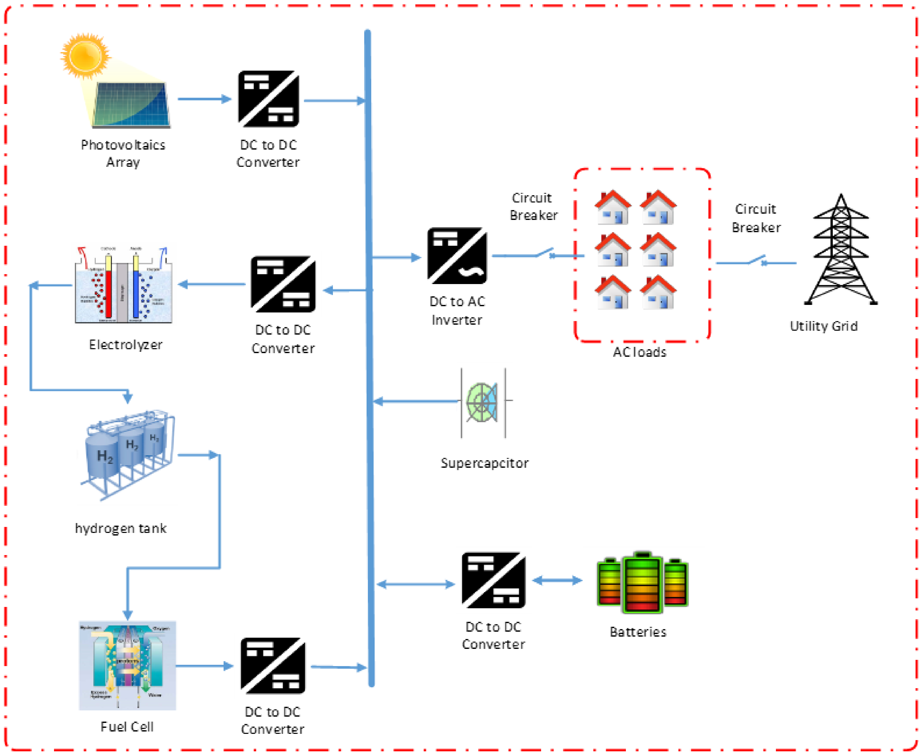
The hybrid microgrid evaluated comprises photovoltaic cells and fuel cells, along with super capacitors and batteries that are used for energy storage, an electrolyzer cell, and AC loads. These systems, when connected, create a small hybrid microgrid, which is connected to a low-voltage AC microgrid for distribution or islanded mode. Figure 1 depicts the configuration of such a hybrid system for the distribution microgrid case. The DC bus is used to interconnect the fuel cells to the boost converter. The battery is connected to the charging regulator using a two-way DC to DC converter, while the super capacitor has a direct connection to the DC bus. The one-way DC to DC converter is used to interconnect the FC and the DC buses, which maintains system stability in spite of varying electrical loads. Batteries are connected to the DC bus using a two-way DC to DC converter.
4. Distributed Hybrid Energy Generation System
4.1. Photovoltaic Cell Modeling
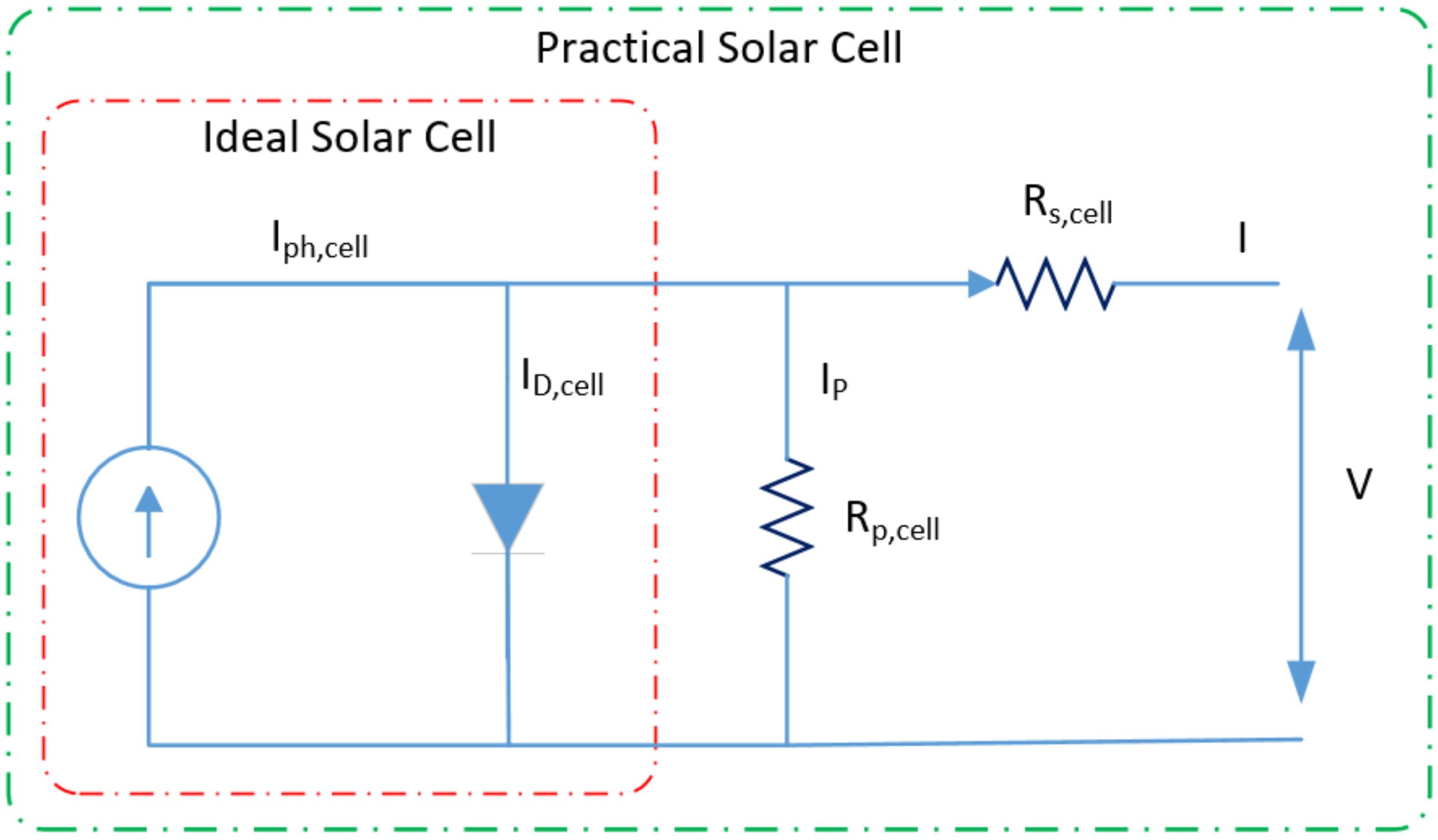
Figure 2 shows an equivalent circuit based on the diode of the solar cell, which can be represented as a parallel resistor, current source, diode, and serial resistance. The current and voltage properties of solar cells are described by the standard mathematical equation (Equation (1)) [21]:
where is reversed leakage current, is photocurrent (A) of photovoltaic, k is Boltzmann’s constant (), q is the electron charge (), and is parallel resistance (Ω). is the series resistance (Ω) and T is the diode temperature.
4.2. Modeling of Photovoltaic Module
As mentioned earlier, the photovoltaic modules are made up of connected photovoltaic cells in parallel form. Therefore, the standard mathematical equation is derived from Equation (2) and the characteristic description of the I–V photovoltaic unit [23] is:
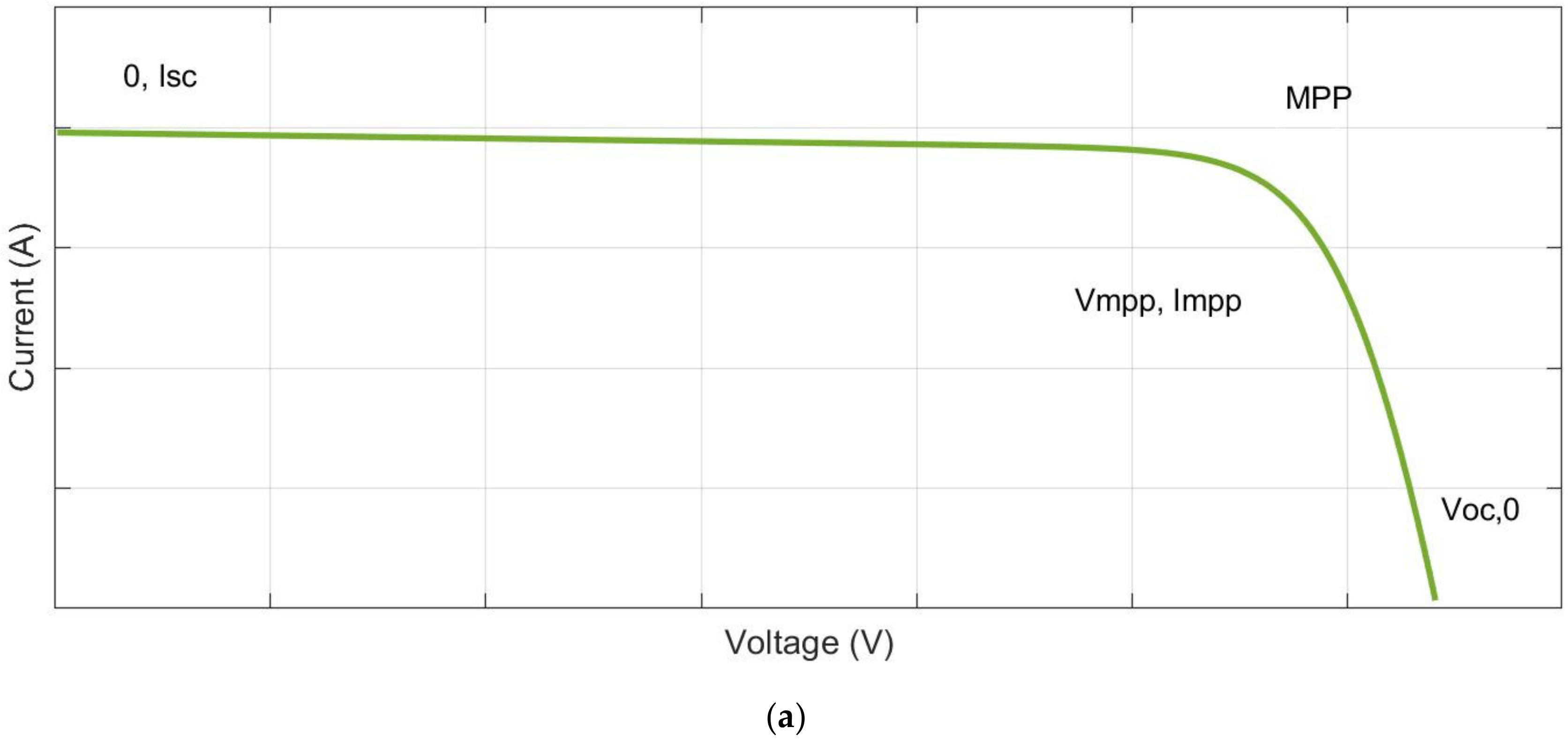
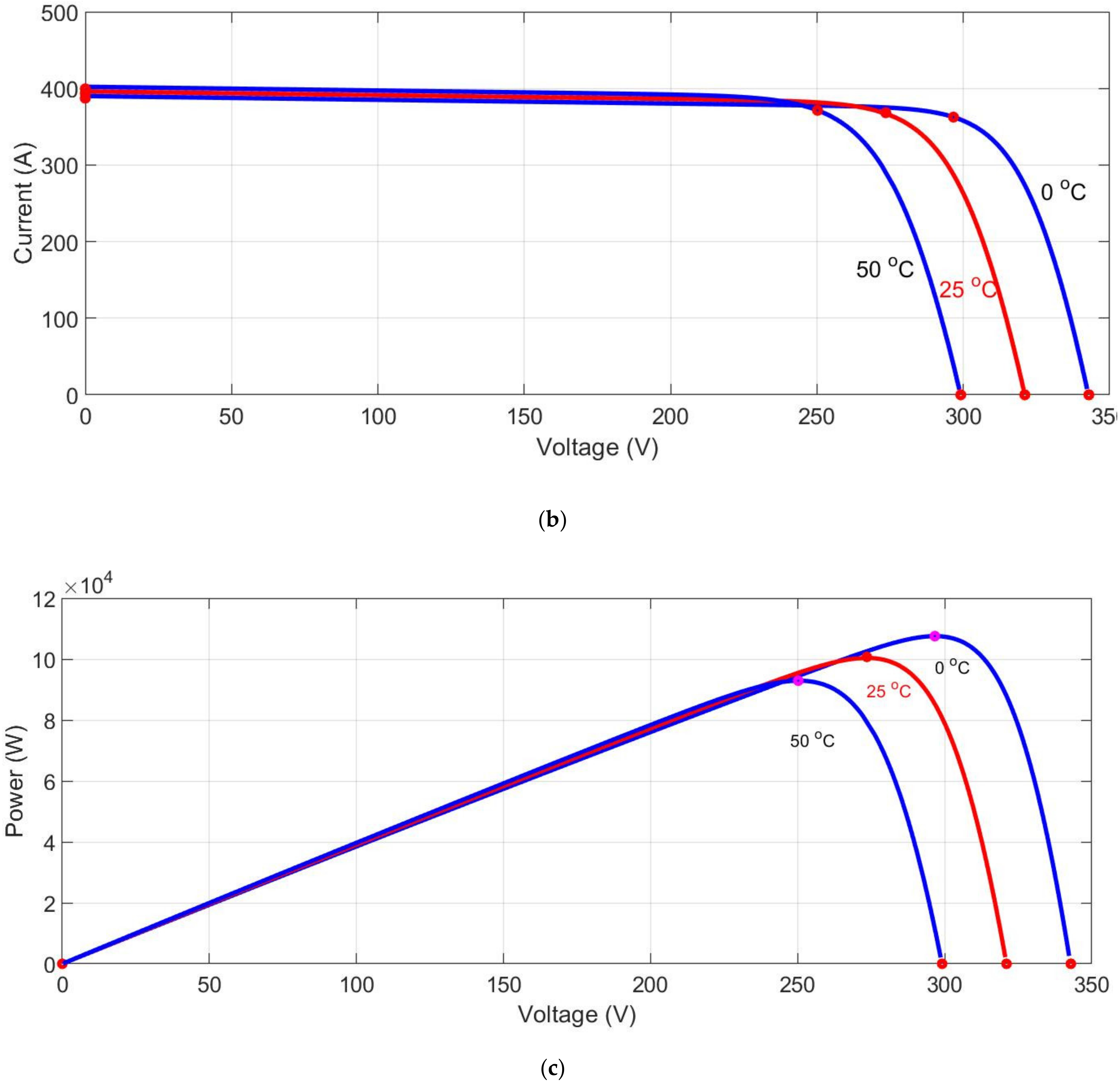
where is the photocurrent (A) of the photovoltaic, is photovoltaic reverse leakage current, is photovoltaic thermal voltage, is parallel resistance, is photovoltaic series resistance, Equation (2) generates the current and voltage curve as illustrated in Figure 4.
The current of a photovoltaic () based on the amount of the photovoltaic irradiance falling on the photovoltaic and the photovoltaic cell temperature corresponds to Equation (3) [24]:
where is the photocurrent, is the photovoltaic irradiance measured in , is the nominal irradiance (), and is the temperature coefficient.
is determined by the Equations (4) and (5):
where is coefficient of temperature and is the open circuit voltage under the nominal conditions.
where is the short-circuit current under the nominal conditions [25].
In this paper, the electrical parameters of the SPR-305E-WHT-D solar photovoltaic are extracted and used to simulate this modular model. These parameters are listed in Table 1.
4.3. Battery Storage System
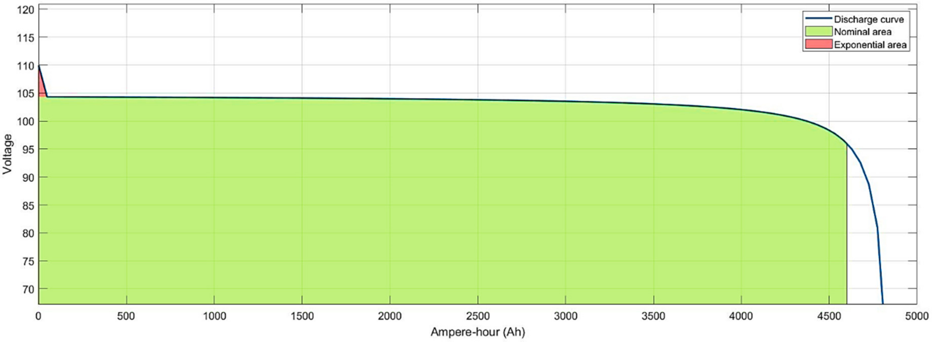
Battery storage systems store additional energy produced by renewable energy systems. However, if there is insufficient energy from the renewable energy generation system, the battery will be discharged to meet the load demand. It consists of a 4800 (Ah) Li-ion battery unit with a rated voltage of 96 VDC. Equations (6)–(9) govern the battery charge/discharge process [26]:
The equations that govern the discharging process of Li-ion batteries are:
The discharge–charge conditions are the same as those of the Ni–MH battery type. In the equations above, the variables and parameters are: , polarization constant (); , battery voltage; , maximum battery capacity, in Ah; , filtered low-frequency current dynamics, in A. In this paper, the electrical parameters of the lithium-ion battery module are extracted and used to simulate this modular model. These parameters are listed in Table 2. Figure 5 illustrates the battery current curves at 0.083333C.
4.4. Loads
The loads consist of residential and commercial loads. Commercial loads appear on asynchronous devices to show the effect of commercial inductive loads, such as air conditioning systems, on the microgrids. Residential loads are designed according to the daily nonseasonal consumption profile of the resort island. Residential loads are simulated according to the actual difference in the specific load profile for the specified resort island.
4.5. Fuel Cell Model
Chemical energy is transformed into electrical energy using fuel cells based on a proton exchange membrane. This hybrid system, consisting of fuel cells and photovoltaics, offers better efficiency along with several other advantages of fuel cells and photovoltaics, which are reduction in carbon dioxide emission, water management, cell stack heating, and the development of cost-effective material. One cell consists of two variants of porous gas diffusion electrodes that separate the electrolyte, thus defining the cell type. The electrolyte consists of a thin conductive film, which conducts cations but restricts the flow of electrons and gases. The fuel cell is fed hydrogen gas from the electrolyzer. At the same time, oxygen enters the cell from the other side and causes a chemical reaction, where hydrogen dissociates into a proton and an electron. The chemical reaction is specified as (Equations (10) and (11)):
Hydrogen dissociation occurs at the left anode, causing a concentration gradient between various electrodes across the membrane. The gradient leads to the protons spreading across the membrane, while the electrons are left behind. The protons drifting towards the cathode provide it a positive charge compared to the anode. Electrons are attracted to the cathode; however, their movement is restricted by the membrane, and the only way for the electrons to reach the cathode is through an external circuit, which causes a current flow. The output voltage VFC(t) for the fuel cell is specified as (Equation (12)):
where , , and are ohmic voltage, activation voltage, mass transport loss, and concentration voltage, respectively. The voltage created by a fuel cell is specified as (Equation (12)):
where refers to electric work, also called Gibbs free energy; F is the Faraday constant; n refers to number of moles; S is the specific entropy; T refers to the operational absolute temperature; is set at °C; , , and are the respective pressures of pure oxygen, hydrogen, and water as fuel; R refers to the gas constant. For the fuel cell stack, the total power output is specified as (Equation (14)):
where and refer to the stacked fuel cell rating and the fuel cell current, respectively. For modeling fuel cell power generation, the primary aspect is the hydrogen mass flow rate. The flow rate, , required by a 1 kW fuel cell, expressed in kg/hour, is specified as (Equation (15)):
where , , and refer to the fuel cell intercept coefficent in kh = g = kW rated, fuel cell curve slope in kg/h/W, and the rated fuel cell capacity in kW. For a fuel cell rated at 1 kW, assuming 1 and 2 at 0.00031 and 0.0581 kg/h/kW, respectively, is determined to be 0.059 kg/h, which indicates that the fuel cell requires this quantity of hydrogen per hour to produce its rated power [27].
4.6. Electrolyzer Model
The electrolyzer uses surplus electricity from the photovoltaic system to produce hydrogen for use in fuel cells, which is stored in a hydrogen tank until it is required. The aspect that requires attention is the quantity of hydrogen produced by the electrolyzer. For a 1 kW electrolyzer, the hydrogen mass-flow rate in kg/hour is specified as (Equation (16)):
where is 1 kW, refers to the heating value of hydrogen (in MJ/kg), and represents the efficency of the electrolyte. Electrolyzer efficiency is assumed to be 90% [28]. Given the heating value of hydrogen at 142 MJ/kg, the hydrogen mass flow would be 0.02268 kg/h/kW. Therefore, the 1 kW electrolyzer will output 0.02268 kg of hydrogen per hour [29].
5. Control Method for Photovoltaics and Full Cell System
5.1. Control of the Converter Interfaced Fuel Cell
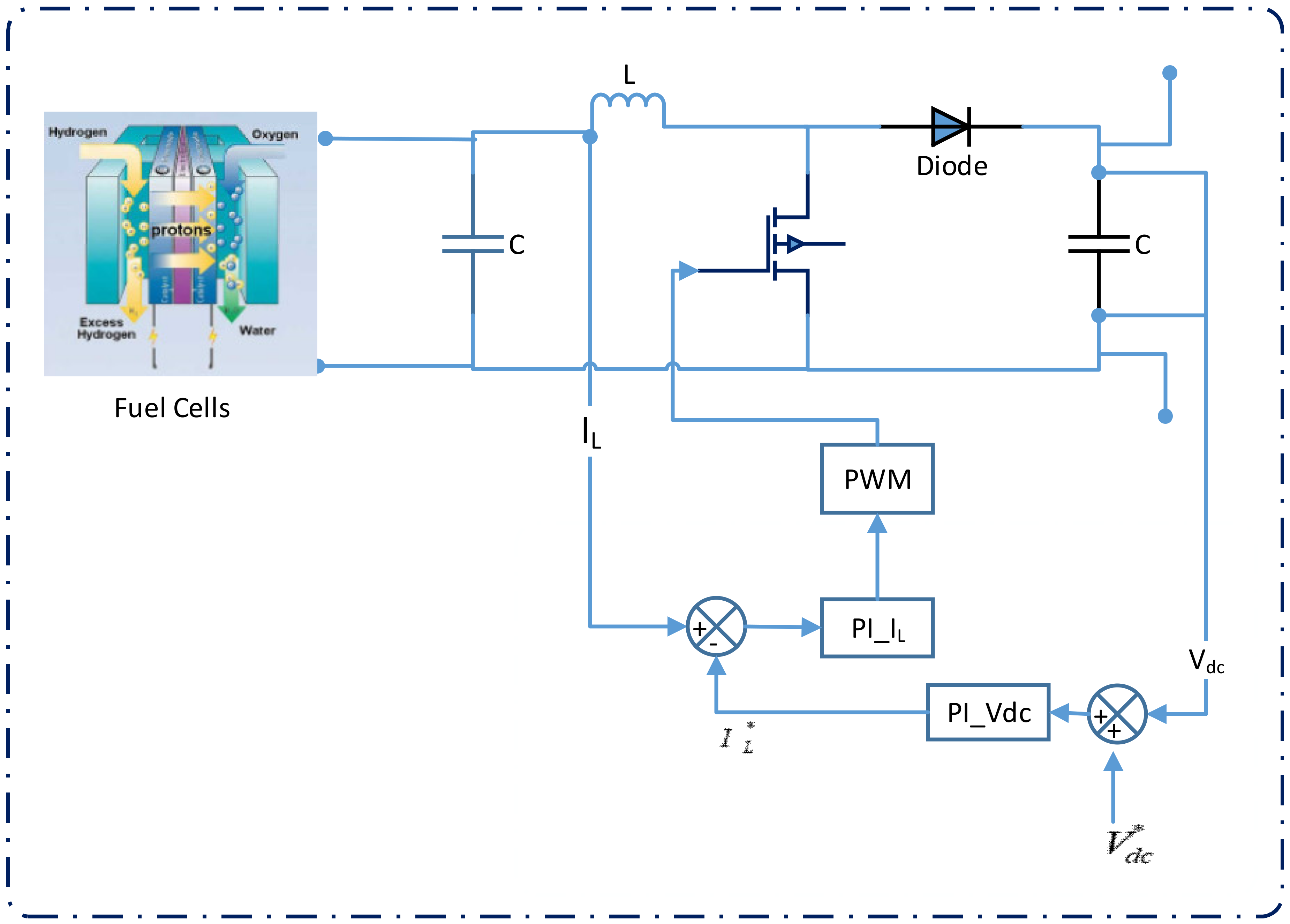
For the boost converter, general control comprising voltage stabilization and output current limitation is used (Figure 6). The current limit is fixed; however, it may be modified for varying sources (for instance, the current should be proportional to the amount of hydrogen injected in a fuel cell, depending on the attributes of the fuel cell). For the test considered in the study, the current is capped at 30 A. The DC reference voltage is aligned to the fixed value needed by the inverter connecting the energy source with the load or the grid. A deviation from the set values is assumed to be an energy deficit or surplus, and is indicated to the power management system. The reference voltage for this control system defines the maximum. Any DC voltage exceeding the maximum causes a decrease in inductor current. When State of Charge (SoC) falls below the reference, the load is powered using the fuel cells. Compared to previous schemes, the current scheme may be implemented with relative ease, while PI (Proportional Integral) gains are regulated online to provide a better response, PWM is the pulse width modulation signal, C is the capacitor, is the voltage of DC bus, L is the inductance.
5.2. Control of the Converter Interfaced Photovoltaics
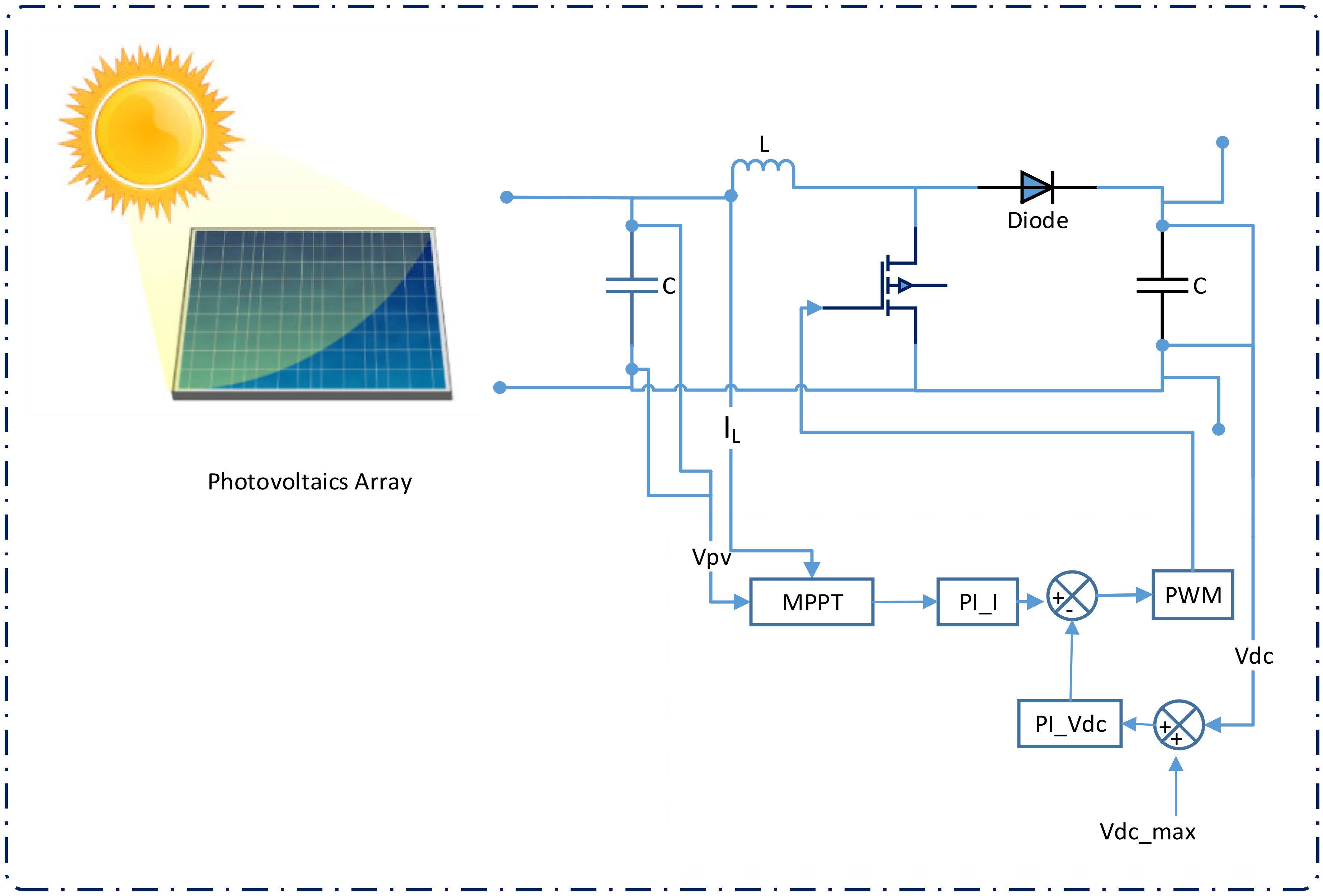
A single-phase boost is used to up the voltage from the panel and control maximum power point tracking. Input current () sensing happens before the measurement of input capacitance () in addition to the panel voltage (). The maximum power point tracking algorithm uses these two values. The MPPT algorithm determines a reference point, which, when maintained at the panel, provides maximum power to be extracted from the PV system. As depicted in Figure 7, MPPT is achieved using the voltage of the outer loop and the current flowing in the inner loop. Hence, the signs for the reference outer voltage compensator and feedback are reversed. The converter output is not adjusted. A voltage feedback mechanism provides input to the internal voltage comparators, which use Pulse-Width Modulation (PWM) in an overvoltage situation to control the voltage from rising beyond the components’ rated voltage.
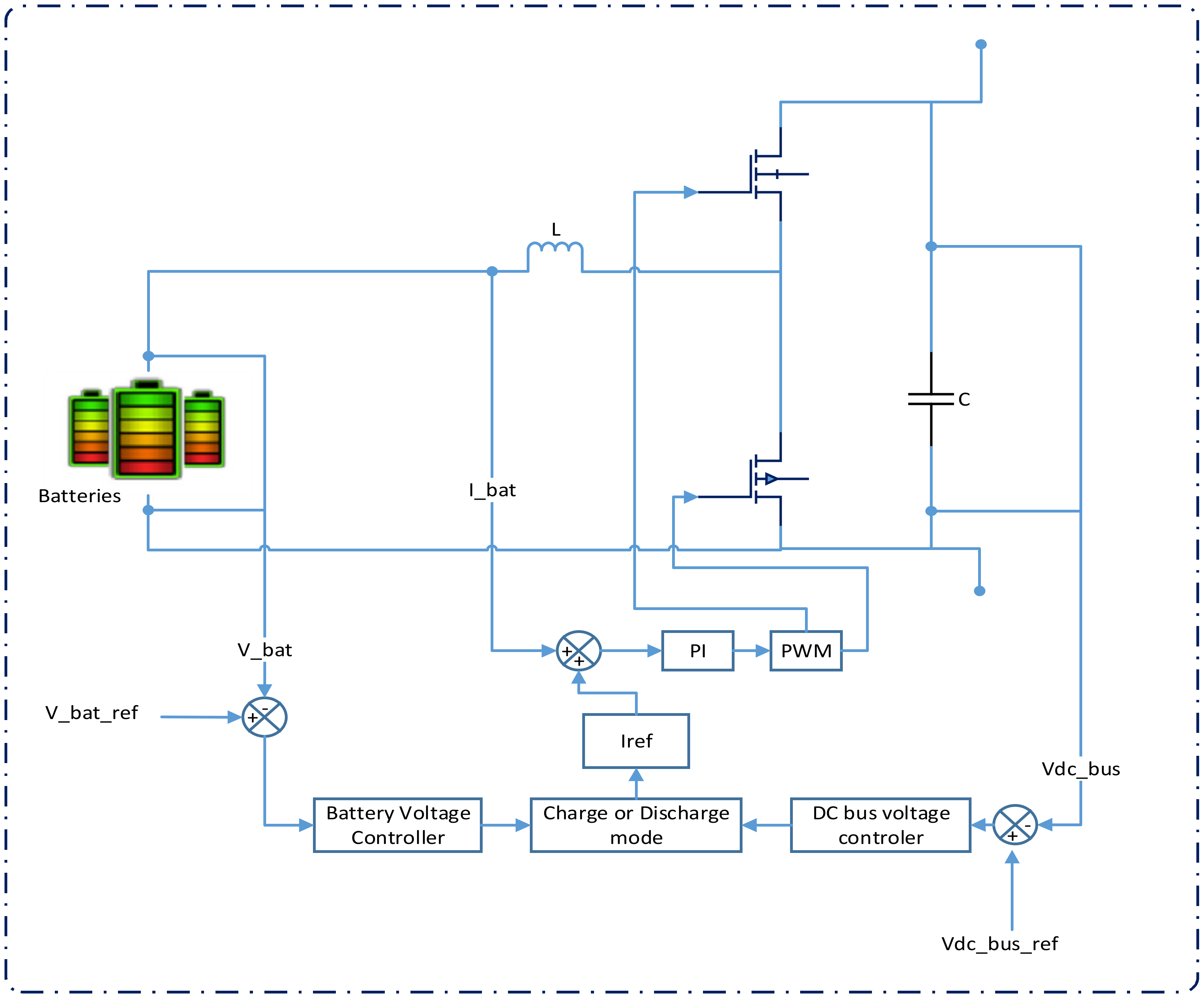
5.3. Control of Bidirectional-Converter Interfacing Battery
In the proposed setup, as depicted in Figure 8, the bidirectional converter has an output filter capacitor (), a high-frequency inductor (L), and two switches (S1 and S2) that permit bidirectional flow of current. The power management system consists of a two-voltage controller with appropriate limitation blocks to provide the necessary power flow under varying conditions. The controllers output a reference current for the storage of energy. The first aspect of control is DC bus voltage regulation, while the other controllers regulate battery voltage. To facilitate better power management in the microgrid, backup energy storage is a part of the system, which comprises a battery connected to the DC bus using a bidirectional converter. The converter serves multiple purposes: it serves as a battery charge regulator in grid-connected operation, and a boost converter to deliver energy from the batteries to the microgrid when the PV and fuel cell sources have insufficient power to feed the local loads in islanded operation. During island mode operation, the optimal operating scenario is the equivalence between load energy requirement and photoelectric power generation, where there is no need for the converter to process energy. Figure 8 depicts the bidirectional control structure and a simplified phase of the power from the converter.
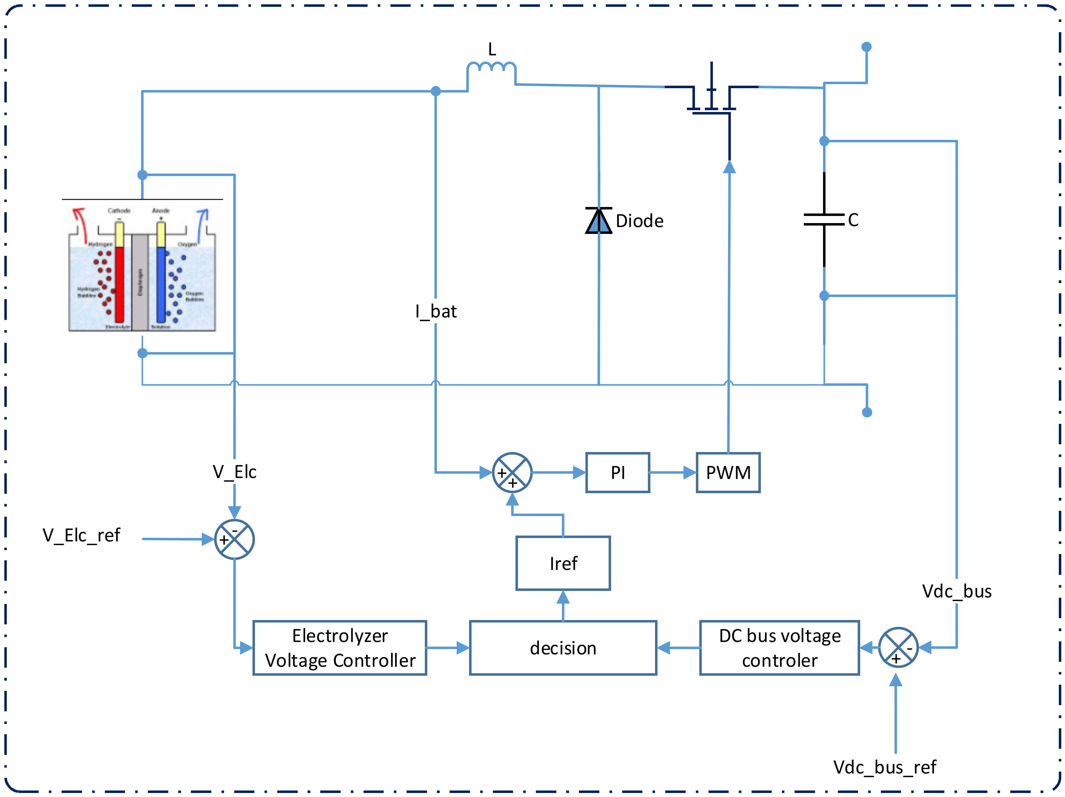
5.4. Control of Converter Interfaced Electrolyzer
The buck converter is a DC to DC power converter which steps down voltage from its input (source) to its output (load). For the buck converter, general control comprising voltage stabilization and output current limitation is used (Figure 9). The input of the buck converter in this system interfaces with the DC bus in the hybrid microgrid, and the output coupling with electrolyzer.
The control system consists of one PI controller, electrolyzer voltage controller, current controller, and DC bus voltage controller. The current control loop should be faster than the voltage control loop to minimize interaction between the two loops and therefore prevent instability. The pulse width modulation stage produces the duty cycle d that is proportional to the control voltage. The pulse width modulator makes a comparison between the control voltage and a reference waveform with peak to peak amplitude Vm. The value for Vm is selected by the designer. The frequency of the waveform corresponds to the desired converter switching frequency fs. This comparison is used to determine the switching on/off of the converter switch. The buck converter purpose, among others, is to act as an electrolyzer charge regulator during the islanded mode and grid-connected mode. Figure 9 depicts the unidirectional control structure and a simplified phase of the power from the buck converter.
5.5. Method of Hybrid Microgrid Control
The proposed microgrid has a control system implemented to stabilize the bus voltage and to regulate the power supply to serve the electrical demand during grid-connected as well as islanded mode. Table 3 lists the specifications for the design of the power management system. In such a control scheme, one unit is the master controller that controls the entire system, whereas the other units act as sources of current (slave). This case would not have a voltage differential between the outputs from the sources since the master unit is responsible for voltage regulation of all outputs. Hence, no current may circulate between the sources.
In the microgrid, the DC bus voltage is quantified and matched against the reference voltage (300 V). Error processing is done using a compensator (PI block) to get the required reference impedance current for the loop. This compensation may be exhibited as the following Equation (17):
The current controller regulates power flow using a comparison of the impedance current flowing through the master unit to the reference value required for system stability. Error processing is conducted using another PI block to get the appropriate duty cycle for the master converter. The PI block can be depicted as Equation (18):
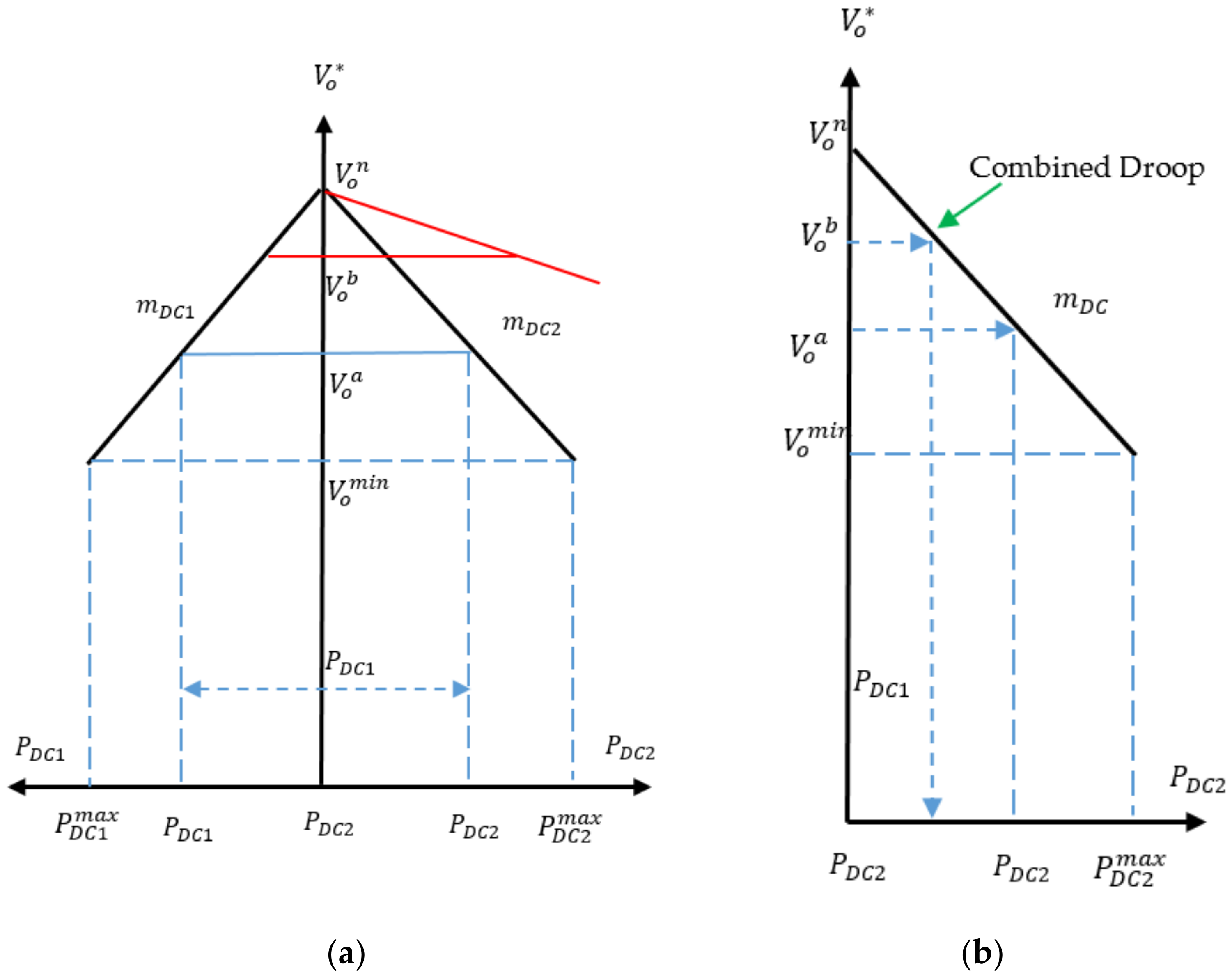
This topology presents the challenge of the master unit requirement. If a fault occurs, the control will not function correctly [30]. To enhance the reliability of the system, three individual sources may act as a master unit, thereby decreasing the chances of a fault in the microgrid control. The model studied has a voltage source converter (VSC) in the master role while the microgrid has a connection with the grid, where voltage and current loops are set up to regulate the voltage levels, so the VSC cannot change the power flow. The energy storage system uses a bidirectional converter to regulate voltage and power levels. During an islanded mode operation of the microgrid, this would be the master control where the voltage shall be maintained at 300 V while meeting the required load. Challenges include faults in the storage system or inappropriate SoC level for the system to operate in the island mode. There is a voltage control system having a voltage and current loop, as depicted in Figure 10.
Drooping-based power sharing is displayed in Figure 10a. Terminal voltage of the DC link for every DC–DC converter is drooped with the DC power generated (), using the droop coefficient , as specified below (Equation (19)):
where , are the reference and no-load DC link voltage of the converter, whereas the j represents a distributed generator unit. The injected DC power from each distributed generator unit () is determined to supply the common DC load () (Equation (20)):
6. Supervisory Control Method of the Proposed System
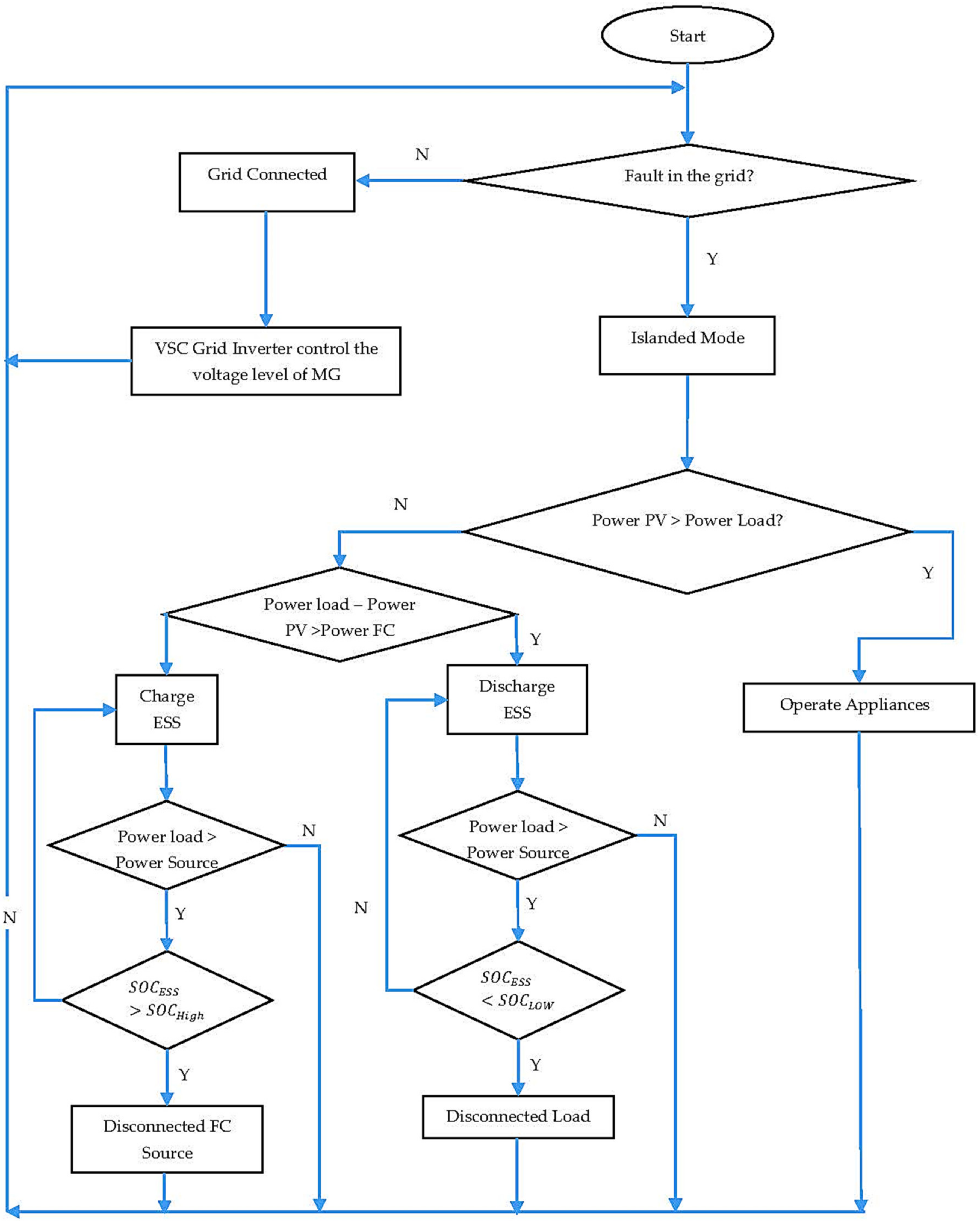
Calculations for the energy produced using the photovoltaic generator are done using temperature and solar radiation as input data points. The photovoltaic output () and the power demanded () are compared to evaluate the energy flow to the storage system and the load. The electrolyzer () produces hydrogen using surplus power generated by the photovoltaic system. During an energy deficit scenario, the backup fuel cell generator () may supply energy using hydrogen. Figure 11 depicts the flow of in a photovoltaic-fuel-cell hybrid system control method. According to Figure 11, the control strategy is based on the following three different cases:
- If > , then = − That is, if the radiation level is high enough, the photovoltaic powers the loads and the excess power is stored in hydrogen by the electrolyzer.
- If < and − ≤ , then − = . That is, if the photovoltaic cannot power the load, then the loads are connected directly to the photovoltaic and the fuel cell is switched on.
- If < and − > , then = = 0 and = .
Meaning, if the PV does not provide power for the load and the fuel cell does not start, the fuel cell and the load are separated, the electrolyzer is connected directly to the PV cells, then the load is connected according to the conditions in 1 or 2. Therefore, super capacitor units, which represent short-term volumes, provide a more stable energy response to transient load changes, or to stabilize fuel cell operation, are not considered here. Also, the electrolyzer of the proposed system is used to generate hydrogen by photovoltaic, so fuel cells can be turned on later when sufficient hydrogen is produced.
There are two levels in the higher-level controller. The first level uses individual component states to establish the operating modes. The second level is integrated with smart systems, which ascertain the way individual components behave in that operational mode. Operating modes consist of the normal mode, super capacitor charging mode, standby mode, battery charging mode, and transient mode. The standby mode has the DC–DC converter operational, while the others are disabled. When the power demand crosses a specific threshold, the controllers switch the mode from standby to transient, which sets up the console to include all controllers. A deficiency in the energy derived from the fuel cells and the battery is corrected using the super capacitor; when fuel is available, the controls switch the super capacitors to the charging mode. The super capacitor may have any magnitude of charge current until it reaches the fully charged state. Both the load and the super capacitor are powered using the fuel cells, while any shortage is supplemented using the batteries. After the super capacitor reaches 100% SoC, the controller transitions to normal load, where only the fuel cell provides power to the loads. This mode consists of the battery being disabled, while the super capacitor is still on. With a spike in load, the controller changes operation to the transient mode.
Battery charging mode may be set in two ways. The first situation, causing a switchover, is the battery state of charge falling below the minimum value. In contrast, the second situation comprises a sudden drop in load, and the batteries SoC is lesser than the maximum. Hence, with decreasing load power, the surplus flows to the battery if it is not fully charged. Splitting the complex control mechanism into several levels provides ease in modeling and controlling the individual components. Those are lower-level controllers, which include a converter controller along with the plant controller balance. The management system is examined for the proper operation of a microgrid in both grid-connected and island modes. Figure 10 depicts the general control.
In the case of grid connections, the master control is handled by the VSC inverter while the sources in the microgrid operate as slaves or sources of current. Hence, the VSC can regulate the DC voltage bus. When an unplanned event occurs, like a fault, a microgrid is required to work in the island mode and should be isolated from the grid. During such a situation, energy storage systems take master control and regulate voltage and power levels in the microgrid. Under all circumstances, the fuel cells and the photovoltaics behave as slave units. Any imbalance between the load and the power produced from the distributed generation sources is corrected by the energy management controls. Such imbalance is addressed by using battery power, given that those have an appropriate state of charge; otherwise, fuel cells are used. It must be noted that fuel cells, because of chemical reactions, respond slowly compared to an energy storage system. If the storage system is malfunctioning or has an unacceptable charge level, the fuel cell becomes the master. In case the microgrid controls are unable to balance the energy flow, and the load exceeds the power generation, the measure of last resort is load rejection. In case there is a power surplus in the grid, the DG (Distributed Generator) systems are disconnected from the microgrid, as required.
7. Energy Management Systems in Houses
In the case of houses, energy management systems incorporate intelligence to decrease energy consumption, enhance uptime, and provide added safety. Control and modeling framework for fuel cells and photovoltaics is designed. This technique uses primary performance attributes like super capacitor voltage, SoC, and DC bus voltage and subject to a proportional integral (PI). Proportional-integral control is straightforward to tune online for improved tracking. The load power is divided so as to permit the fuel cells to provide the steady load. An integrated system comprising these power sources may be considered by adding the current values where the system connects with the microgrid. The real power traded between the hybrid microgrid and the utility network is addition of power generated by the fuel cells (), batteries , and the photovoltaic system , and the electrical load (Figure 1) (Equation (21).
During extended periods, rapid power variations in regard to the super capacitor may be disregarded.
Equation (22) is specified for an extended time frame:
For such a short duration, the super capacitor, due to its rapid response time, takes control of power flow. Using the inverse of Equation (21), reference power for the super capacitor may be expressed as (Equation (23)):
Super capacitors have a very swift charge/discharge response, and, therefore, they are employed in this study for voltage control on the DC bus for the hybrid microgrid. The following constraints should be factored in when determining the energy storage capacity of super capacitors (Equation (24)):
where and are, respectively, the maximum and minimum permissible storage capacity for the supercapacitor. may be calculated as per Equation (25):
Therefore, the larger the power drawn from the super capacitor, the stored energy reduces likewise (Equations (26) and (27)).
Battery storage capacity is subject to the following constraints (Equations (28)–(35)):
Equations (29) and (30) stand for the power capacity constraints of the battery for charging and discharging status. Equation (31) keeps the simultaneous occurrence of discharging and charging of the battery. Finally, Equations (32)–(35) are related to SoC or the level of the stored energy in the battery. In the above equations, , , and stand in the charging power, discharging power, and the maximum available power from the battery, respectively. Also, and are ancillary binary variables indicating the charging or discharging status of the battery.
House-based microgrids may trade power with the utility grid. Any energy surplus produced by the microgrid after the batteries are fully charged could be sold to the grid. If the total production of the microgrid is insufficient to meet the load, power should be bought from the utility grid (Equation (36)).
Energy management and power control systems are very important for hybrid networks based on intermittent sources. The photoelectric control provides reference voltage (V_MPP) for the unidirectional converter. With the converter controlling the PV output, PV works at the voltage that uses the maximum power. Super capacitor discharge and charge circuit control maintains a DC voltage with a constant value of 270 V. Even with DC voltage ripples, controlling the transformer at the end of the load makes the load voltage as smooth as possible. Fuel cells can instantly provide maximum energy. The boost transformer sets the performance limit. Low capacitance and induction values accelerate transients and accelerate overall response, but require faster switches.
8. Results of Proposed System
Hybrid systems are corroborated by applying a thorough model in the environment of Simulink. This model represents a different emergency power system which is based on super capacitors, fuel cells, and Li-ion batteries. The proposed model also includes different power handling systems for fuel cell fusion power supplies. The findings are attained based on the standard profile of daily load for scrutinized homes, as displayed in Figure 12. Table 4 presents the details of the power system under study.
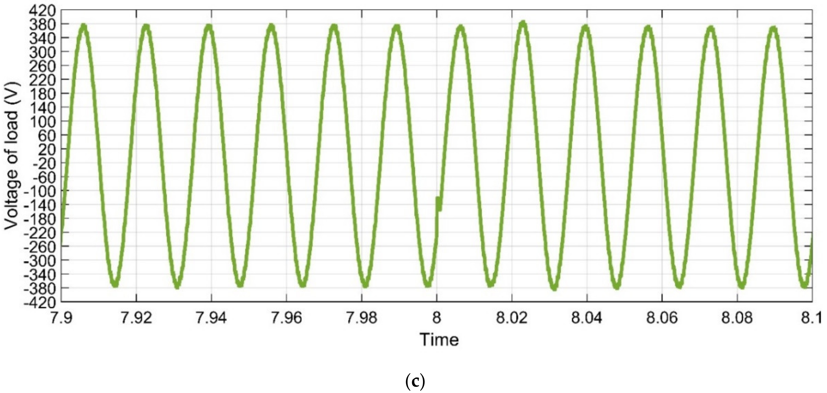
The 25 kV utility grid is connected to houses via a “25 KV/270 V line to line (V_rms)” transformer to step down voltage to the required grid voltage, which means the output of the transformer equal to 380 V line to line peak voltage (), meaning the transformer output voltage is equal 220 V line to ground.
where is the peak line to line voltage, is the RMS (Root Mean Square) line to line voltage, is the peak line to neutral voltage.
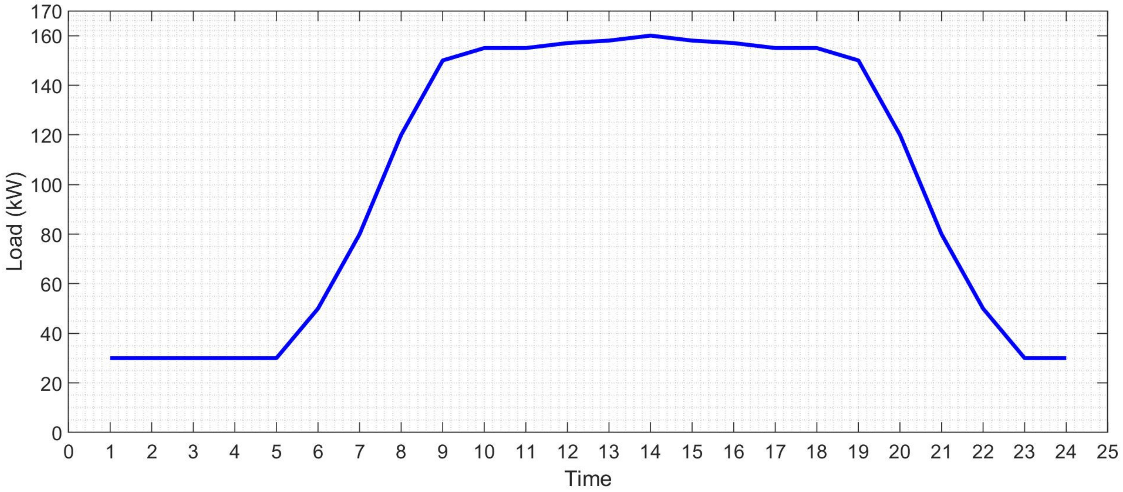
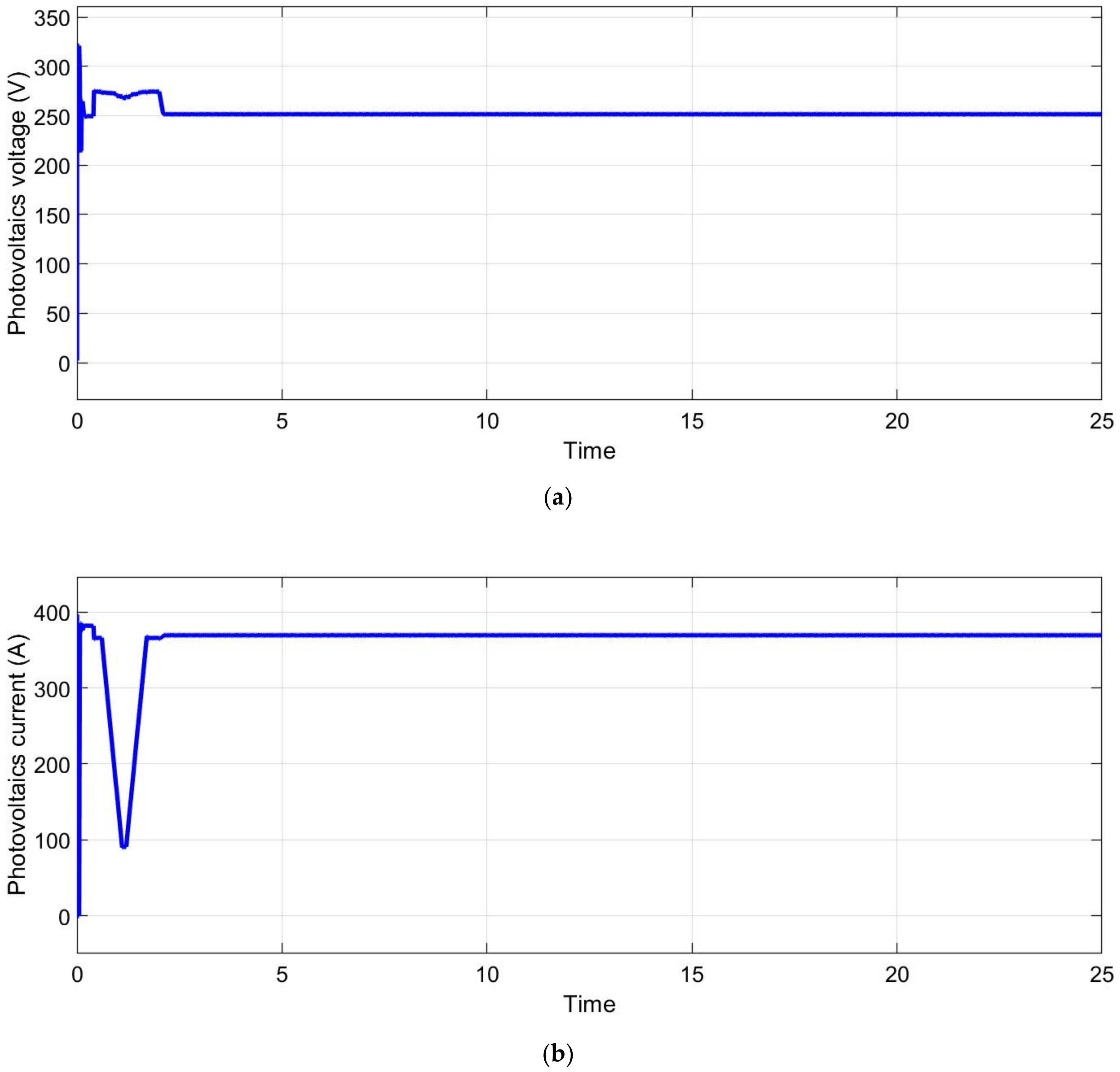
The three-phase AC loads with variable power factor and apparent power are used to simulate a residential load profile. The energy management system distributes energy between sources according to the given energy management strategies. The peak electrical load is 160 kW at 3 p.m., while the lowest load occurs at 29 kW from 10:30 p.m. to 8:30 a.m. Figure 13 shows the photoelectric voltage and photoelectric current. Photovoltaic power generation is set to track the maximum power point proportional to radiation. The meteorological data for the hybrid power generation system of photovoltaic/fuel cells are the amount of solar radiation (W/m2) and ambient temperature (°C). These typical weather data are collected every hour. The microgrid reference generated is set to one real energy step (25 s, Figure 13) and the energy detected between the microgrid and the main line is very close to the power reference. Super capacitors and batteries compensate for the differences in the reference power of the microgrid and all the differences of the negative energy of the microgrid (total load and photoelectric cells).
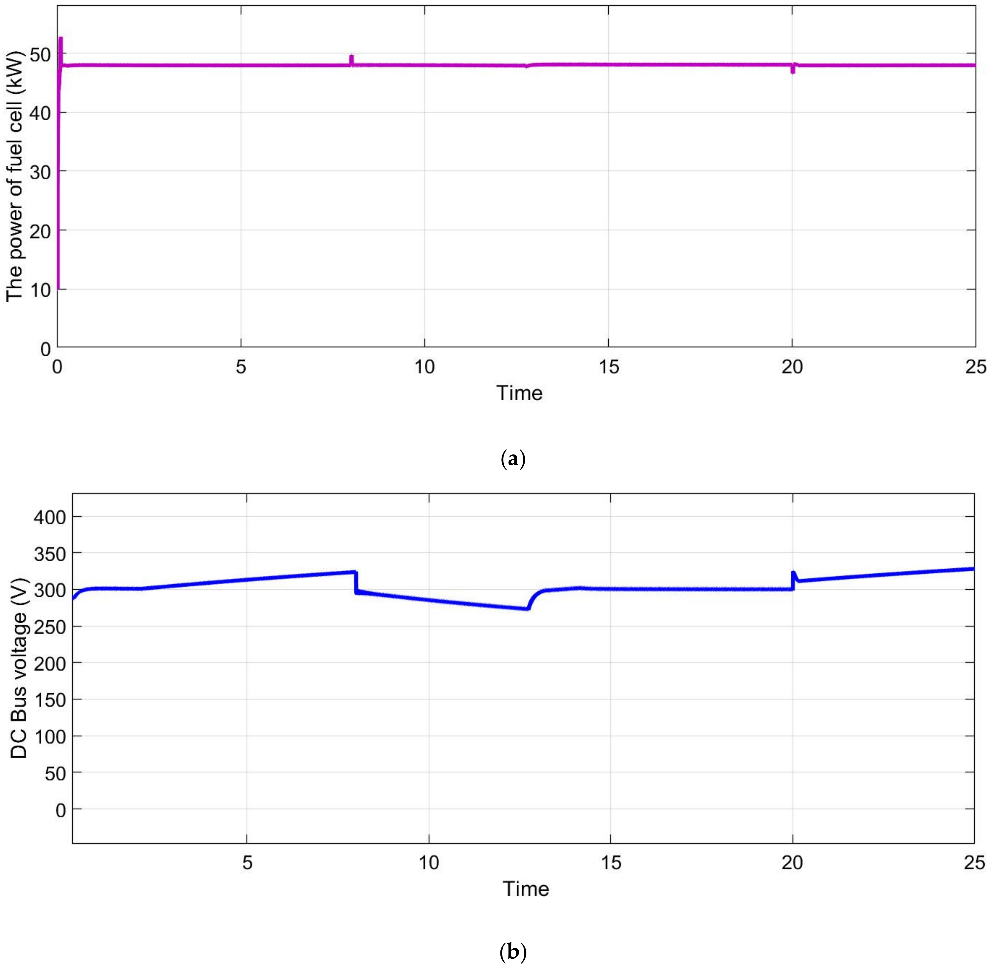
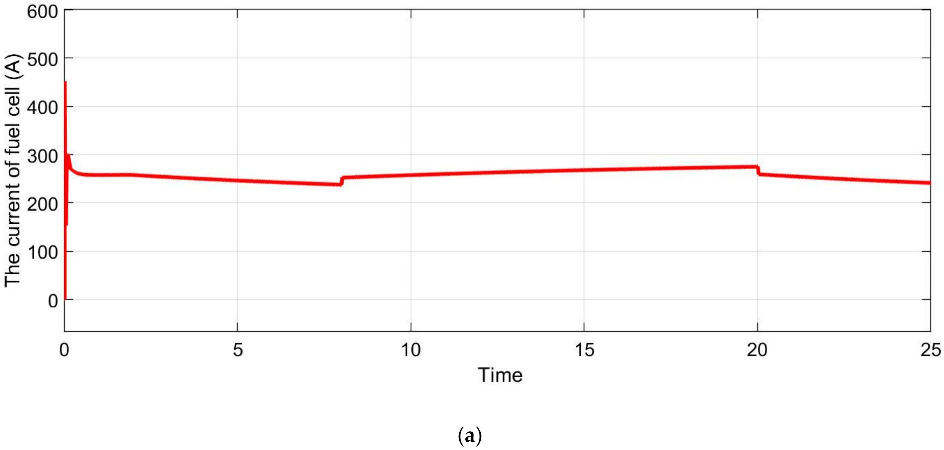
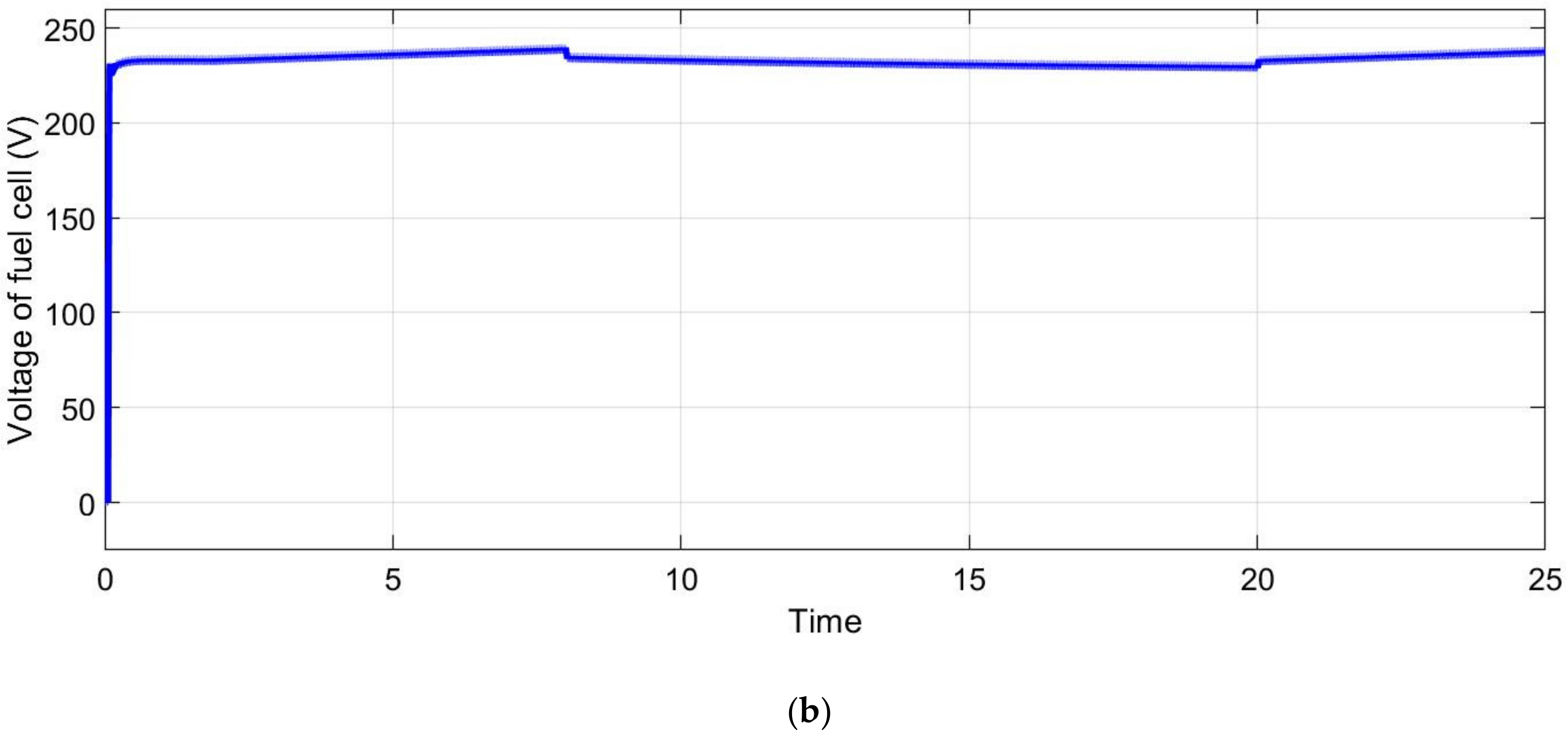
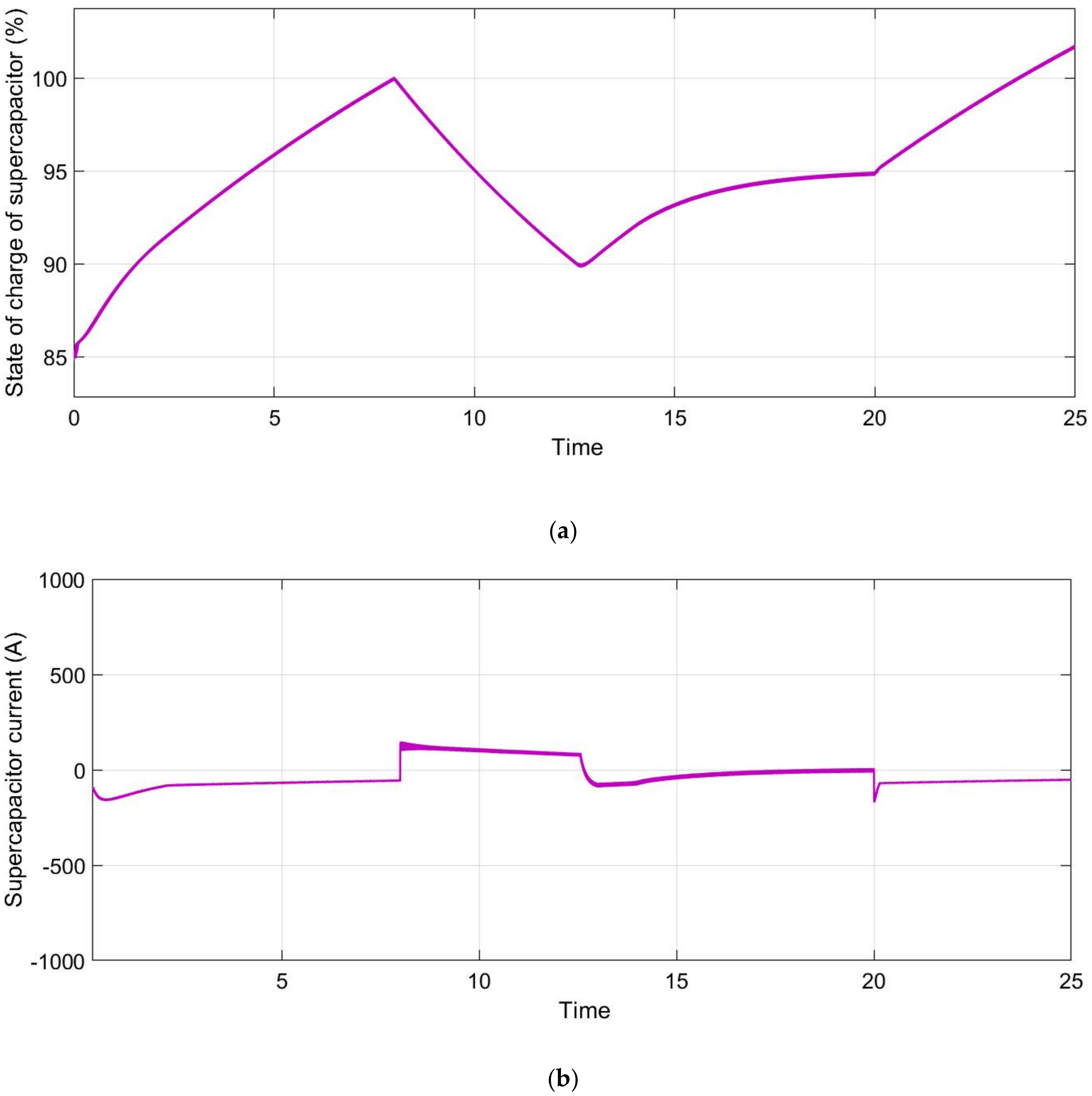
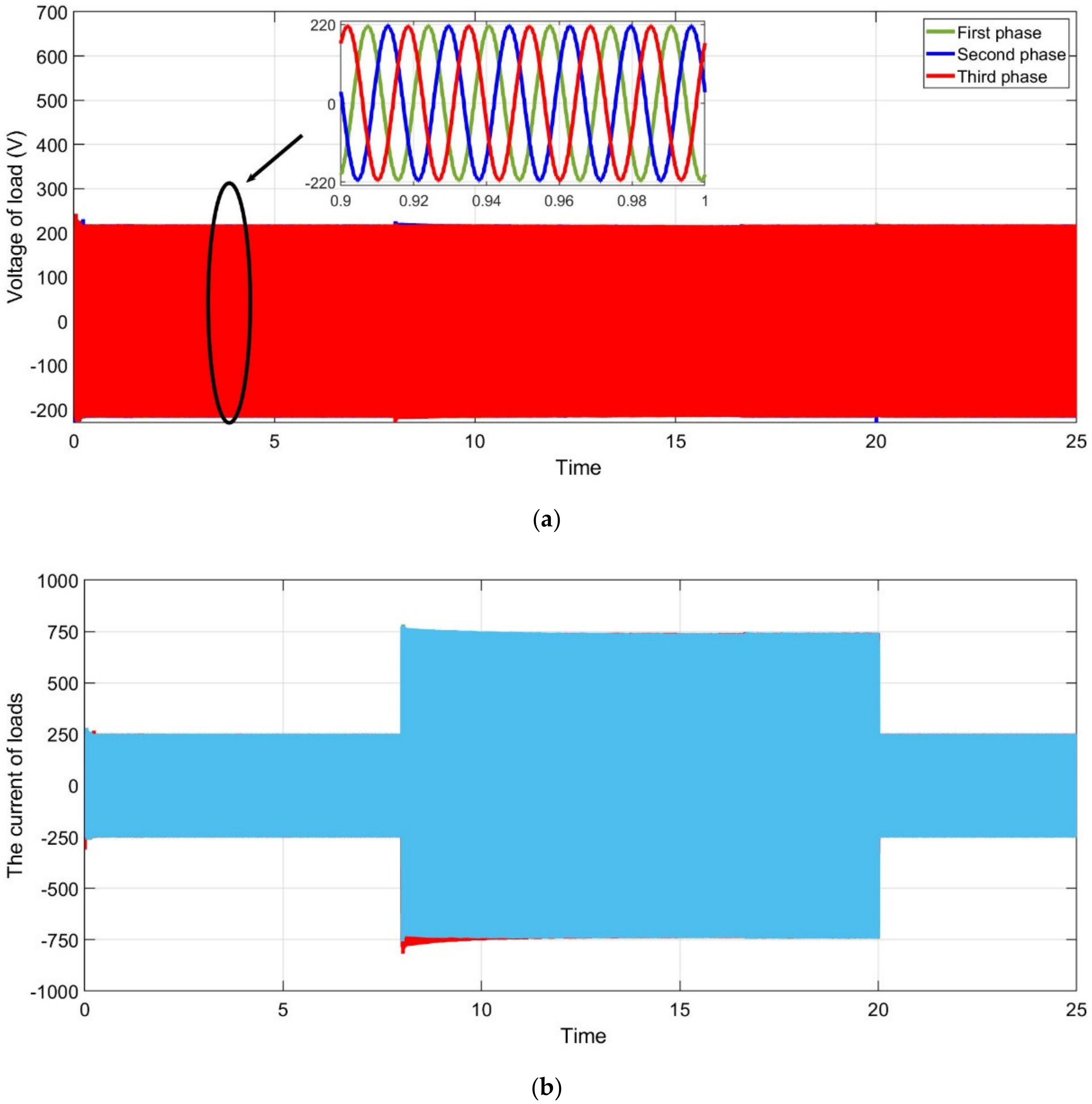
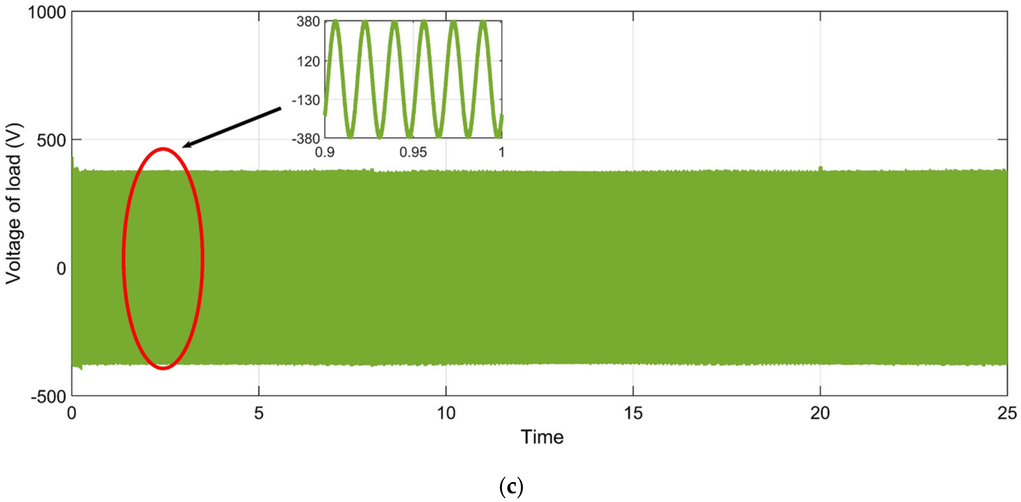
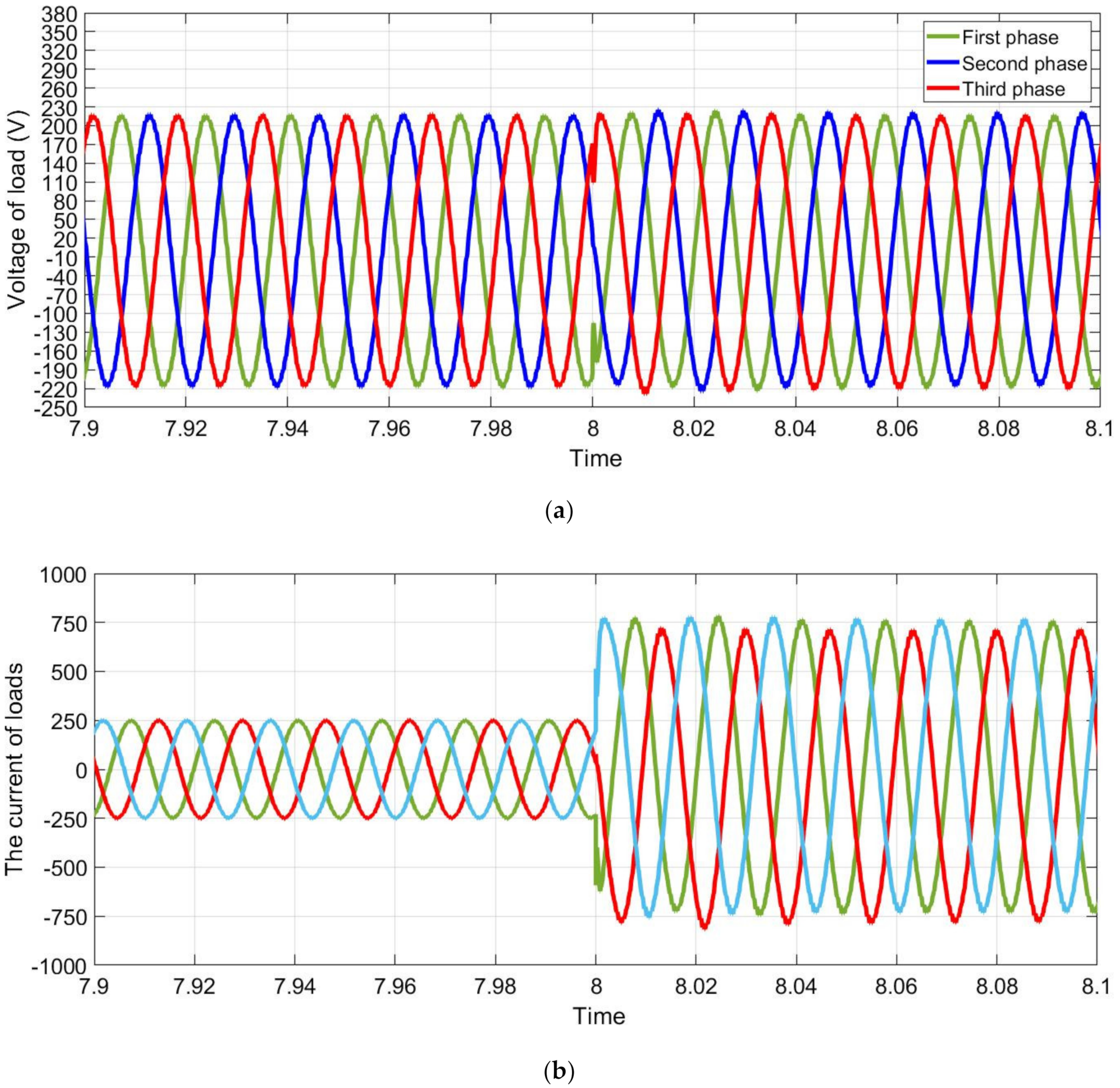
It can be seen that the fast power fluctuation due to the slow response time of the fuel cell is reduced in the short-term energy storage system, as shown in Figure 14. The fuel cell will try to charge the super capacitor to increase the SoC if the load is not too high. Figure 15 shows the fuel cell voltage and fuel cell current. Note that a positive super capacitor current means that the super capacitor will supply the load, and a negative current means that the super capacitor will be charged. In this case, the carrier voltage fluctuates in the permissible range from 226 to 270 V. The super capacitor voltage is properly controlled between 226 and 270 V, as shown in Figure 16c. SoC range for super capacitors is 85–100%. Figure 17 shows the load voltage and load current. The load current increases in 8 s and decreases in 20 s. As shown in Figure 18, the voltage decreases due to the sudden increase in the load current.
In this study, the fuel cell and photovoltaic hybrid power generation structure is either the island or grid-connected mode. The load demand regions are determined by a preset power. Nonetheless, most resident energy consumption of power, like lighting and apparatus, is always varying. Based on the scheme of energy management, the energy regulation system manages the power of every power supply apparatus through the reference signals of the photovoltaic and fuel cell converter, together with super capacitors, batteries, and fuel cells. A description of what happens in a virtual emergency situation follows. At t = 0 s, the primary load is provided by the chief generator, which switches on the fuel cell hybrid system, to plan for an emergency scenario. Now, the fuel cell starts recharging the battery as well as the super capacitor using its optimal power. At time t = 8 s, every load is connected and the loads soar to 160 kW. At this moment, the extra power needed is instantly provided by the super capacitor because of its fast dynamics, although the power in the fuel cell increases gradually. At time t = 13 s, the super capacitor gets discharged and its DC bus voltage goes below the required amount (270 V) and the battery starts supplying power to control the DC bus voltage to 270 V. At time t = 20 s, the DC bus or super capacitor voltage gets to 270 V and gradually the power of the battery drops down to zero. The fuel cell supplies complete load power and keep on recharging the super capacitor. At t = 13 s time, the battery also gets to its highest power and the super capacitor supplies additional load power. At time t = 20 s, the load power reduces below the fuel cell maximum power. Due to the slow fuel cell dynamics, the extra fuel cell power during transients is transferred to the supercapacitor. Owing to the fuel cells’ slow dynamics, power during transients is shifted towards the super capacitor. At time t = 20 s, the power of the load is reduced and falls below the fuel cell highest power, and the additional fuel cell power is shifted towards both the super capacitor and battery. At time t = 23 s, the load power gets reduced rapidly. The additional fuel cell energy gets stored in the batteries and super capacitor. The fuel cell provides nearly all the total load power needed and decreases its power gradually to its optimum and the battery gets recharged.
9. Conclusions
In this study, the new home management system demonstrates the effectiveness of this method to deliver constant power to the customer through different controller designs. Moreover, this paper recommends an effective control scheme for the effortless shift from grid-connected mode to island mode because of unintentional islanding. Furthermore, a technique for smart management and regulation was employed to ensure optimum functioning of a hybrid microgrid formed using different renewable energy sources, as well as different energy storage devices. Using this energy management strategy as component of the control design of a grid-linked microgrid can reduce the total operational cost. The regulatory control was included in the control model to correct any variation among the primary grid power and the intended reference power by altering the reference fixed power of the battery provided by this energy management system. This study put forward a full local regulatory design for the recommended system. The local controller regulates the local power, DC bus voltage, and the current of the microgrid where the local controller’s aim is to follow the fixed point of the monitoring controller. The outcomes show that the suggested robust energy management and regulation scheme in the hybrid microgrid system, which is based on ecofriendly energy, supports nominal use of the utility grid power. The proposed scheme is able to distribute power amongst the distributed generator components even under uneven conditions. Moreover, from the outcomes, it is apparent that the output voltage of the unit terminals of the distributed generator gets higher when the unit of fuel cell is attached along with the super capacitor and the photovoltaic. The loads of the houses for the hybrid microgrid were taken into account and the hybrid microgrid can swap power with the transmission grid. The hybrid microgrid used in this research is highly reliable.
The outcomes suggested that the alternating integration of solar energy sources and fuel cell in the microgrid should be devised carefully in individual operation. The recommended control schemes provide exceptional performance under various operating conditions. Batteries improve the system reliability since they store additional renewable energy when the demand is low and supply energy when the demand is high.
For future work, these results suggest (1) implementing the strategy presented on a real network and comparing the results, and (2) investigating the effects of other uncertain parameters, such as fuel cost, on microgrid planning.
Author Contributions
B.N.A.: writing—original draft, software, methodology, and validation; M.D.E.: formal analysis, investigation, resources, writing—review and editing; B.H.J.: supervision, funding, writing—review and editing. All authors have read and agreed to the published version of the manuscript.
Funding
This research received no external funding.
Conflicts of Interest
The authors declare no conflict of interest.
References
- Justo, J.J.; Mwasilu, F.; Lee, J.; Jung, J.W. AC-microgrids versus DC-microgrids with distributed energy resources: A review. Renew. Sustain. Energy Rev. 2013, 24, 387–405. [Google Scholar] [CrossRef]
- Basak, P.; Chowdhury, S.; Nee Dey, S.H.; Chowdhury, S.P. A literature review on integration of distributed energy resources in the perspective of control, protection and stability of microgrid. Renew. Sustain. Energy Rev. 2012, 16, 554–556. [Google Scholar] [CrossRef]
- Moradi, M.H.; Hajinazari, M.; Jamasb, S.; Paripour, M. An energy management system (EMS) strategy for combined heat and power (CHP) systems based on a hybrid optimization method employing fuzzy programming. Energy 2014, 86, 86–101. [Google Scholar] [CrossRef]
- Ma, X.; Wang, Y.; Qin, J. Generic Model of a Community-Based Microgrid Integrating Wind Turbines, Photovoltaic, and CHP Generations. Appl. Energy 2013, 112, 147–582. [Google Scholar] [CrossRef]
- Alonso, M.; Amaris, H.; Alvarez-Ortega, C. Integration of Renewable Energy Sources in Smart Grids by Means of Evolutionary Optimization Algorithms. J. Expert Syst. Appl. 2015, 39, 22–55. [Google Scholar] [CrossRef]
- Zhang, Y.; Gatsis, N.; Giannakis, B. Robust Energy Management for Microgrid with High-Penetration Renewables. IEEE Trans. Sustain. Energy 2015, 4, 45–53. [Google Scholar] [CrossRef] [Green Version]
- Lujano-Rojas, J.M.; Monteiro, C.; Dufo-López, R.; Bernal-Agustín, J.L. Optimum Load Management Strategy for Wind/Diesel/Battery Hybrid Power Systems. J. Renew. Energy 2015, 44, 288–295. [Google Scholar] [CrossRef]
- Delgado, C.; Navarro, D. Optimal Design of a Hybrid Renewable Energy System. In Proceedings of the 2014 Ninth International Conference on Ecological Vehicles and Renewable Energies (EVER), Monte-Carlo, Monaco, 25–27 March 2014. [Google Scholar] [CrossRef]
- Helal, S.; Najee, J.; Hanna, M.; Shaaban, F.; Osman, A.; Hassan, S. An Energy Management System for Hybrid Microgrids in Remote Communities. Can. Conf. Electr. Comput. Eng. 2019, 1275–1286. [Google Scholar] [CrossRef]
- Correa, C.; Marulanda, G.; Garces, A. Optimal microgrid management in the colombian energy market with demand response and energy storage. In Proceedings of the 2016 IEEE Power and Energy Society General Meeting (PESGM), Boston, MA, USA, 17–21 July 2016; pp. 145–156. [Google Scholar] [CrossRef]
- Dufo, R.; Agustín, B. Optimization of Control Strategies for Stand-Alone Renewable Energy Systems with Hydrogen Storage. Renew. Energy 2007, 34, 124–134. [Google Scholar] [CrossRef]
- Das, B.K.; Al-Abdeli, Y.M.; Kothapalli, G. Effect of Load Following Strategies, Hardware, and Thermal Load Distribution on Stand-Alone Hybrid CCHP Systems. Appl. Energy 2018, 4, 34–45. [Google Scholar] [CrossRef]
- Luna, A.; Meng, L.; Diaz, N.; Graells, M.; Vasquez, J.; Guerrero, J. Online Energy Management Systems for Microgrids: Experimental Validation and Assessment Framework. IEEE Trans. Power Electron. 2018, 33, 134–146. [Google Scholar] [CrossRef]
- Abedini, M.; Moradi, H.; Hosseinian, S. Optimal management of microgrids including renewable energy sources using GPSO-GM algorithm. Renew. Energy 2016, 56, 45–55. [Google Scholar] [CrossRef]
- Marzband, M.; Azarinejadian, F.; Savaghebi, M.; Guerrero, J. An Optimal Energy Management System for Islanded Microgrids Based on Multipored Artificial Bee Colony Combined with Markov Chain. IEEE Trans. Sustain. Energy 2017, 45, 67–87. [Google Scholar] [CrossRef] [Green Version]
- Rouholamini, M.; Mohammadian, M. Heuristic-Based Power Management of a Grid-Connected Hybrid Energy System Combined with Hydrogen Storage. Renew. Energy 2016, 89, 12–24. [Google Scholar] [CrossRef]
- Almada, B.; Leão, R.; Sampaio, F.; Barroso, G. A Centralized and Heuristic Approach for Energy Management of an AC Microgrid. Renew. Sustain. Energy Rev. 2016, 45, 67–87. [Google Scholar] [CrossRef]
- Merabet, A.; Tawfique, A.; Ibrahim, K.; Beguenane, R.; Ghias, A. Energy Management and Control System for Laboratory Scale Microgrid Based Wind-PV-Battery. IEEE Trans. Sustain. Energy 2017, 8, 217–224. [Google Scholar] [CrossRef]
- Farzin, H.; Firuzabad, F.; Moeini-Aghtaie, M. Stochastic Energy Management of Microgrids during Unscheduled Islanding Period. IEEE Trans. Ind. Inform. 2017, 13, 1079–1087. [Google Scholar] [CrossRef]
- Battistelli, C.; Agalgaonkar, Y.; Pal, B. Probabilistic dispatch of remote hybrid microgrids including battery storage and load management. IEEE Trans. Smart Grid 2017, 8, 1305–1317. [Google Scholar] [CrossRef]
- Hussaian Basha, C.; Rani, C.; Brisilla, R.M.; Odofin, S. Mathematical Design and Analysis of Photovoltaic Cell Using MATLAB/Simulink. Soft Computing for Problem Solving. Adv. Intel. Syst. 2019, 1048, 711–726. [Google Scholar] [CrossRef]
- Sangwongwanich, A.; Blaabjerg, F. Mitigation of Interharmonics in PV Systems with Maximum Power Point Tracking Modification. IEEE Trans. Power Elect. 2019, 34, 8279–8282. [Google Scholar] [CrossRef] [Green Version]
- Rakhshan, M.; Vafamand, N.; Khooban, M.H.; Blaabjerg, F. Maximum Power Point Tracking Control of Photovoltaic Systems: A Polynomial Fuzzy Model-Based Approach. IEEE J. Emerg. Sel. Top. Power Electron. 2018, 6, 292–299. [Google Scholar] [CrossRef]
- Subramaniyan, A.B.; Pan, R.; Kuitche, J.; TamizhMani, G. Quantification of En-vironmental Effects on PV Module Degradation: A Physics-Based Data-Driven Modeling Method. IEEE J. Photovolt. 2018, 8, 1289–1296. [Google Scholar] [CrossRef]
- Bilal Naji, A.; Basil, H.J.; Anvari-Moghaddam, A.; Blaabjerg, F. A New Robust Control Strategy for Parallel Operated Inverters in Green Energy Applications. Energies 2020, 13, 3480. [Google Scholar] [CrossRef]
- Fathima, A.H.; Palanisamy, K. Optimization in Microgrids with Hybrid Energy Systems—A Review. Renew. Sustain. Energy Rev. 2015, 45, 431–446. [Google Scholar] [CrossRef]
- Mao, L.; Jackson, L.; Davies, B. Effectiveness of a novel sensor selection algorithm in PEM fuel cell on-line diagnosis. IEEE Trans. Ind. Electron 2018, 65, 7301–7310. [Google Scholar] [CrossRef] [Green Version]
- Ghenai, C.; Salameh, T.; Merabet, A. Technical economic analysis of off-grid solar PV/fuel cell energy system for residential community in desert region. Int. J. Hydrog Energy 2018, 6, 97–105. [Google Scholar] [CrossRef]
- Ghenai, C.; Bettayeb, M. Optimized design and control of an off-grid solar PV/hydrogen fuel cell power system for green buildings. IOP Conf. Ser. Earth Environ. 2017, 93, 1–11. [Google Scholar] [CrossRef]
- García, P.; Torreglosa, J.; Fernández, L.; Jurado, F. Control Strategies for High-Power Electric Vehicles Powered by Hydrogen Fuel Cell, Battery and Supercapacitor. Expert Syst. Appl. 2016, 40, 4791–4804. [Google Scholar] [CrossRef]
Figure 1.
The proposed hybrid microgrid system structure.

Figure 2.
The circuit of photovoltaic cell based on single diode mode.

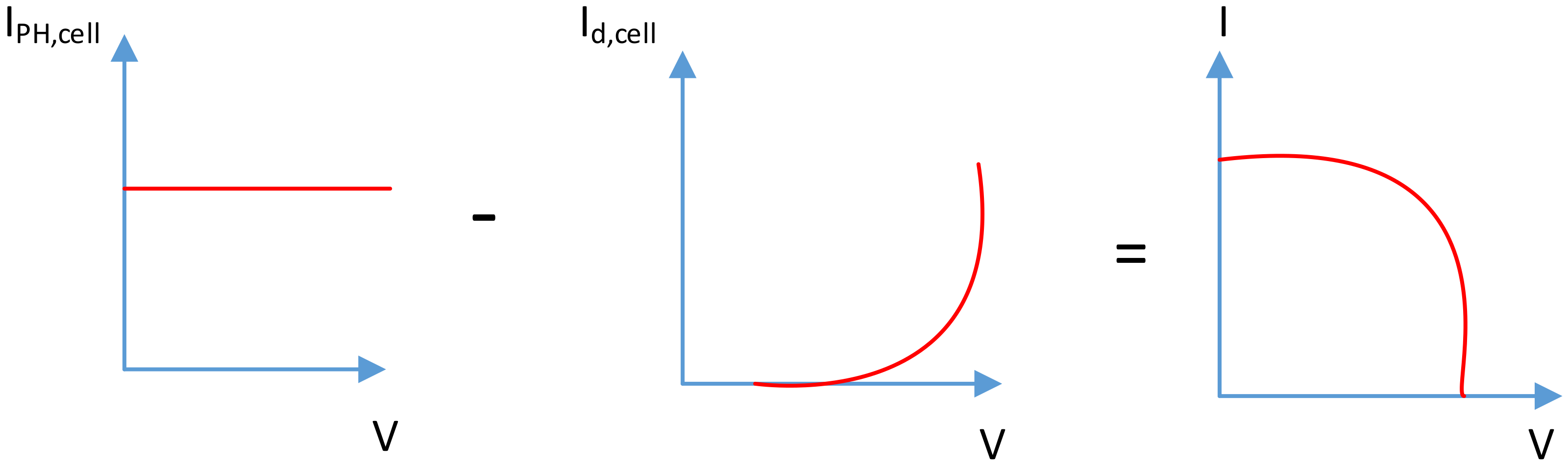
Figure 3.
Typical photovoltaic current and voltage curves.

Figure 4.
(a) A typical current–voltage curve of the photovoltaic (PV), (b) current–voltage curves of a photovoltaic at different temperature levels and constant irradiation, (c) Power–voltage curves of a photovoltaic at constant irradiation and different temperature levels.
Figure 4.
(a) A typical current–voltage curve of the photovoltaic (PV), (b) current–voltage curves of a photovoltaic at different temperature levels and constant irradiation, (c) Power–voltage curves of a photovoltaic at constant irradiation and different temperature levels.


Figure 5.
The battery current curves at 0.083333C (400A).

Figure 6.
The control of the fuel cell converter.

Figure 7.
Control of the converter with maximum power point tracking.

Figure 8.
The control of battery storage.

Figure 9.
The control of the electrolyzer buck converter.

Figure 10.
The droop curve: (a) droop curve of two distributed generators and (b) the droop for the entire DC subgrid.
Figure 10.
The droop curve: (a) droop curve of two distributed generators and (b) the droop for the entire DC subgrid.

Figure 11.
The proposed energy management control system.

Figure 12.
The curve of demand.

Figure 13.
(a) Photovoltaics voltage and (b) photovoltaics current.

Figure 14.
(a) Fuel cell power and (b) DC bus voltage.

Figure 15.
(a) Fuel cells current and (b) fuel cells voltage.


Figure 16.
(a) State of charge of the super capacitor, (b) super capacitor current, (c) super capacitor voltage.
Figure 16.
(a) State of charge of the super capacitor, (b) super capacitor current, (c) super capacitor voltage.


Figure 17.
(a) Line to neutral loads voltage, (b) loads current, (c) line to line load voltage.


Figure 18.
(a) Step change in load line to neutral voltage at 8 a.m., (b) step change in load current at 8 a.m., (c) load line to line voltage at 8 a.m.
Figure 18.
(a) Step change in load line to neutral voltage at 8 a.m., (b) step change in load current at 8 a.m., (c) load line to line voltage at 8 a.m.


Table 1.
Electrical parameters of the SPR-305E-WHT-D photovoltaic.
| Parameters | Value |
|---|---|
| Series connected modules | |
| Parallel string | |
| Voltage of open circuit | |
| Maximum voltage | |
| Temperature coefficient of | −0.27269 (%/°C) |
| Short-circuit current | |
| Maximum current | |
| Temperature coefficient of | 0.061745 (%/°C) |
| Shunt resistance | 269.5934 Ω |
| Series resistance | 0.37152 Ω |
| Diode ideality factor | 0.945 |
| Diode saturation current | (A) |
| PV type | SPR-305E-WHT-D |
| Number of cells | 96 |
Table 2.
Electrical parameter of lithium-ion battery module.
| Parameters | Values |
|---|---|
| Capacity | |
| Voltage | |
| Initial State of Charge (SoC) | |
| Battery response time | (s) |
| Voltage of fully charged | |
| Current of discharge | |
| Voltage of cutoff | |
| Resistance |
Table 3.
The requirements of energy-management design.
| Item | Symbols | Values |
|---|---|---|
| Power of fuel cell | – | 40–50 (kW) |
| Depth of battery discharge | – | 60–90 (%) |
| Voltage of DC bus | – | 280–330 (V) |
| Nominal voltage of fuel cell | 250 (V) |
Table 4.
The parameters of the proposed system.
| Item | Description |
|---|---|
| Photovoltaics | 100 kW |
| Proton exchange membrane (PEM) fuel cell | 50 kW (peak) |
| Capacity of battery | |
| Voltage of battery | |
| Initial SoC of battery | |
| Voltage of the fully charged of battery | |
| Current of battery discharge | |
| Super capacitor | 291 V, 15.6 F, (six 48.6 V cells in series) |
© 2020 by the authors. Licensee MDPI, Basel, Switzerland. This article is an open access article distributed under the terms and conditions of the Creative Commons Attribution (CC BY) license (http://creativecommons.org/licenses/by/4.0/).
Share and Cite
MDPI and ACS Style
Naji Alhasnawi, B.; Jasim, B.H.; Esteban, M.D. A New Robust Energy Management and Control Strategy for a Hybrid Microgrid System Based on Green Energy. Sustainability 2020, 12, 5724. https://0-doi-org.brum.beds.ac.uk/10.3390/su12145724
AMA Style
Naji Alhasnawi B, Jasim BH, Esteban MD. A New Robust Energy Management and Control Strategy for a Hybrid Microgrid System Based on Green Energy. Sustainability. 2020; 12(14):5724. https://0-doi-org.brum.beds.ac.uk/10.3390/su12145724
Chicago/Turabian StyleNaji Alhasnawi, Bilal, Basil H. Jasim, and M. Dolores Esteban. 2020. "A New Robust Energy Management and Control Strategy for a Hybrid Microgrid System Based on Green Energy" Sustainability 12, no. 14: 5724. https://0-doi-org.brum.beds.ac.uk/10.3390/su12145724
Note that from the first issue of 2016, this journal uses article numbers instead of page numbers. See further details here.