A Study on Recent Developments and Issues with Obstacle Detection Systems for Automated Vehicles


1
Mechanical and Systems Engineering School, Newcastle University, Newcastle upon Tyne NE1 7RU, UK
2
Engineering Systems and Management (ESM), Aston University, Birmingham B4 7ET, UK
*
Author to whom correspondence should be addressed.
Sustainability 2020, 12(8), 3281; https://0-doi-org.brum.beds.ac.uk/10.3390/su12083281
Submission received: 18 March 2020
/
Revised: 9 April 2020
/
Accepted: 15 April 2020
/
Published: 17 April 2020
(This article belongs to the Special Issue Methods for Improving Sustainability of Passenger and Freight Transport)
Abstract
:This paper reviews current developments and discusses some critical issues with obstacle detection systems for automated vehicles. The concept of autonomous driving is the driver towards future mobility. Obstacle detection systems play a crucial role in implementing and deploying autonomous driving on our roads and city streets. The current review looks at technology and existing systems for obstacle detection. Specifically, we look at the performance of LIDAR, RADAR, vision cameras, ultrasonic sensors, and IR and review their capabilities and behaviour in a number of different situations: during daytime, at night, in extreme weather conditions, in urban areas, in the presence of smooths surfaces, in situations where emergency service vehicles need to be detected and recognised, and in situations where potholes need to be observed and measured. It is suggested that combining different technologies for obstacle detection gives a more accurate representation of the driving environment. In particular, when looking at technological solutions for obstacle detection in extreme weather conditions (rain, snow, fog), and in some specific situations in urban areas (shadows, reflections, potholes, insufficient illumination), although already quite advanced, the current developments appear to be not sophisticated enough to guarantee 100% precision and accuracy, hence further valiant effort is needed.
1. Introduction
According to the World Health Organisation, in 2015, there was a total of 1.25 million traffic accidents, 270,000 people fatalities, resulting in over 700 life losses each day on average [1]. It was reported that over 90% of crashes were based on driver error [2]. To improve this situation, governments, car manufacturers and municipal departments have considered a large amount of investment to support the development of various technological solutions, including autonomous driving and cognitive robotics, where around 1 billion euros have already been invested by EU agencies [3].
In 2009, companies like Google and Uber, together with traditional car manufacturers like BMW and FORD, developed and piloted the first self-driving car prototype, which was tested in 4 states in the US [4]. Since then, this type of technology has evolved, and, currently, there are 33 states in the US where specific regulations related to autonomous driving have been introduced. In addition, the Victoria Transport Policy Institute has predicted that this technology will be widely used after the 2040s and 2050s [5]. In 2014, the Society of Automotive Engineers (SAE) proposed some operational requirements for autonomous (also called unmanned) driving (Figure 1). SAE defined six levels in this field, where for levels 0–2 human drivers still monitor the driving environment and operating conditions. Whilst for levels 3–5, a fully automated driving system is proposed to replace completely the function of human drivers [5].
With the continuous development of the highways, roads, city streets and expressways, increasing efforts have been devoted to developing an obstacle detection system for vehicles [6]. Current developments suggest that such a system now integrates functions of identifying positions, distance measurement, and automated braking when a potential risk of failure and collision is detected.
The Advanced Driver Assistance Systems (ADAS) have been invented, which include an intelligent computing unit that provides an accurate image of the driving environment. Other components of ADAS include adaptive cruise control, parking assistance, and lane-keeping assistance. Through ADAS, autonomous driving will be possible. The system will fully replace human drivers, improve road efficiency, increase traffic safety and ameliorate the traveller’s experience.
The main focus of this work is to discuss current developments and existing technologies for obstacle detection that can make autonomous driving possible in the near future. A thorough review of different technical and technological solutions is offered, followed by discussions on certain advances and limitations of existing systems, including visual cameras, LIDAR, RADAR, SONAR and IR. Discussions on how different technologies perform in different situations during daytime or at night and when dealing with, e.g., shadows, colours, and reflections from smooth surfaces, are also presented.
The key takeaways from this review include
- Radar: Performs mapping at medium to long range. Better than cameras and LIDAR in the worse weather possible, but lacks the fine resolution required for object identification.
- LIDAR: Provides 360-degree high-resolution mapping, from short to long range. Limited by harsh environments with low reflective targets.
- Ultrasound: Low cost and shows good performance in short-range measurement. Suitable for parking assistant in parking lots due to its fast response in a relatively short range.
- Camera: Provides a complete picture of the environment in a variety of situations, as well as able to accurately read road signals and colour buttons, but are limited by the visibility conditions within the driving environment.
- Infrared (IR): Gives excellent support for night vision among all sensors. LIDAR can also be used during night time because of its capabilities to work in low-visibility environments.
- Combining different technologies gives a more accurate detection, surveillance and recognition of the driving environment and all surroundings, including vehicle and pedestrian, lane and other objects; but, still, further effort is required to develop more precise sensor fusion systems.
- Data collected from different technologies is not homogeneous; as a result, a sophisticated data fusion mechanism is needed for accurate data analytics.
- In both extreme weather conditions (rain, snow, fog) and some specific situations in urban areas, although quite advanced, the current technological developments are not sophisticated enough to guarantee 100% precision and accuracy of obstacle detection. Hence, further work is needed.
The rest of this paper is organised as follows: In Section 2, the purpose of obstacle detection systems in automated vehicles is discussed. Section 3 looks at technologies and existing systems for obstacle detection like LIDAR, RADAR, vision camera, and ultrasonic sensors. Combining different technologies is also discussed, followed by an application of different technological solutions for accurate detection and measurement of objects and obstacles in day time or at night. Critical questions about data collection, data fusion, and data processing are also discussed. Section 4 reviews challenges with obstacle detection when dealing with shadows, colours and in extreme weather conditions. Section 5 extends the review by looking at several specific situations in urban areas (e.g., exhaust, reflections from smooth surfaces, paying attention when opening the door) that require particular attention. Section 6 offers conclusions followed by avenues for future work presented in Section 7.
2. The Purpose of Obstacle Detection System
Human beings spend more time on daily driving than ever before. With the higher density of cars on the roads and city streets, it is sometimes difficult for the human drivers to distinguish immediately and clearly identify static and moving objects and obstacles like trollies, buggies, pedestrians, bicycles, and cyclists. Consequently, reliable obstacle detection systems are needed to operate in real-time to detect any potential risk of collision and signal so that evasive reaction can take place [7].
The emphasis has been gradually transferred from manual control of mechanical systems to software/computing units for decision-making, where operation systems can manipulate the whole vehicle by itself. With the more complexity of the driving surroundings, the vehicle must be equipped with more detecting and analysing modules to achieve smooth and safe autonomous driving. Currently, the most advanced cars may have more sensors and software on them than a fighter airplane [8], but they still cannot guarantee safety on the road. That is why it is critical to ensure a precise obstacle detection mechanism [9] is in place that can easily detect static and moving objects that may present risks of crash and impact when driving.
There are two methods to consider: active and passive. Generally speaking, the active method refers to sensors with laser sender and receiver, such as RADAR/LIDAR or ultrasound. The frequency and direction can be controlled and manipulated by the system itself or the driver. In contrast, the passive method is based on passive scene measurements, like cameras [7]. The detection system has to respond according to what is captured and received through camera images but no choice to select what object or where to scan.
Reliable obstacle detection systems must handle a huge amount of information and data, which is collected and processed in real-time. For this to happen, an “active” approach (Figure 2) is employed and implemented. Specifically, an active approach refers to an autonomous system having the ability for intelligent decision-making in regards to image capturing and data acquisition [3]. Here, the primary functions are road detection as well as obstacle detection [10]. Generally speaking, the processes include perceiving information via sensors, estimating and evaluating the risk, and finally providing feedback to the driver for further actions, if required [9].
For the human visual system, the eyes move, and the visual sensitivity is extremely high [3]. The image captured by human eye when perceiving the world can contain several GB of information with a single blink if converted from an abstract scale into a computing number for easier comparison, while the latest generation obstacle detection system is only able to deal with MB data in a short period. In urban areas, there would be around 300 million points in each square kilometre in a 3D point cloud, which is regarded as too bulky for internal storage [11,12].
Through data collection, data fusion and data processing, the estimation of time before impact with another object can be calculated and shown on a screen. When this system “thinks” that there is a possibility of a crash, and the distance to static or moving objects is too close, an alarm informs the driver to slow down or bypass. According to SAE, the first 3 levels, so-called semi-autonomous vehicles, require a human driver to interact with a computing system, which serves as a back-up in case there is some failure of the software. So here, there is a state of “disengagement”, which includes a switch mode [11]. Additionally, in extreme situations, when there is no response from the driver towards the warning message, this mode is to take action and activate the brakes automatically so that a possible collision with another vehicle and or object can be avoided.
3. Technology and Existing Systems
3.1. Background
Like human drivers, the autonomous vehicles (AVs) have to ensure a continuous observation of the driving environment and all surroundings [13]. Five key elements are involved: the obstacle, the road, the ego-vehicle, the environment, and the driver [9]. Amongst these, the obstacle with its different properties—size, shape, weight, material, frequency of appearance—is the most significant element to focus on. To provide AVs with the abilities to detect an obstacle and obtain information about its properties, sensors are integrated and installed in and around the vehicle.
Recently, some vehicle manufacturers already have made some progress on this front. For example, the pilot assist system by VOLVO, which consists of cameras and RADAR, gives warnings and auto-steering turning when a critical situation occurs. BMW has demonstrated pedestrian alert, lane-departure warning and lane-change warning, which are all components of obstacle detection technology; please see the Daimler-Benz VIsion Technology Application project (VITA). Other components of safety-related systems involve the anti-lock braking system (ABS), electronic stability control (ESC), and latest emergency brake automation (AEB) [9]. The general requirement for these systems is for them to be simple, reliable and accurate enough in terms of real-time data processing [12]. Table 1 shows luxury commercial vehicles of different brands equipped with autonomous support functions. It appears that autonomous freeway driving, semi-autonomous parking and braking are the most common functions amongst these brands. The autonomous lane-change function is only available in Tesla Model S.
3.2. RADAR/LIDAR
In addition to the traditional image-based 3D modelling technology using cameras, there is an obstacle detection technology with remote sensors and fast-capture image functions using laser [14]. To achieve the obstacle detection function, hardware and software must work closely with each other. The combination of RADAR (radio detection and ranging) and LIDAR (light detection and ranging) can capture images and transfer them through electrical interfaces. Then an in-vehicle micro-computer will process the information acquired and analyse the data. Afterwards, all signals and images will be displayed on the dashboard for the driver to utilise.
Distance detection is one of the major functions of LIDAR. By measuring the travelling time of light pulse between the sender and photodetector after reflection of the target surface, the distance refers to d = /2 (d, v, and t represent distance, light velocity and time between journey, respectively). With this function, LIDAR traditionally serves to obtain 3D geometry of objects, in fields of civil-engineering, architecture, and current autonomous driving applications [15].
As for trains, in order to achieve obstacle detection, different types of sensors have been used, e.g., video cameras (optical passive), LIDAR (optical active) and RADAR (electromagnetic active). Initially, several conditions of the train, like its position on the track or driving speed, can be obtained by virtual sensors. A computer system unit will process the information captured by the sensors and then give a warning to the train driver in case there is a potential obstacle detected ahead. As a result, such a function can cause automatic braking or simply give a warning by sound to the driver [16].
Light laser has higher energy, higher frequency and shorter wavelength than radio waves, which gives a better reflection rate in non-metallic material [15]. It can operate with a wider range of electromagnetic spectrum such as ultraviolet, visible and infrared regions [17].
LIDAR on vehicles can be divided into two categories: short-distance LIDAR and two-dimensionally scanning long-distance LIDAR.
The remote 3D LIDAR sensing system calculates the target position according to the process as below [18]:
- i.
- Filtering: A pre-processing step to separate non-ground objects from ground information, which can reduce the data size and shorten the calculation time afterwards.
- ii.
- Data structuring: The geometry information about objects detected is encoded with X, Y, Z coordinates, and then fit into grids [14].
- iii.
- Segmentation: Point Cloud Library (PCL), an open-source software with VC++ language [19], can create clusters based on the Euclidean algorithm.
- iv.
- Cluster detection: With the aid of statistical means and histograms, the target cluster would be separated by visualization software from the other clusters (due to its nature, this process can be quite complicated and time-consuming).
- v.
- Detection with software: Terrasolid finally utilizes a progressive densification algorithm to classify and label the target category and other objects; for example, in the case of Anandakumar’s research, detecting buildings from the background together with plants.
LIDAR has several advantages: accurate, wide field of range, long-distance range, irrelevant to different light conditions [20]. However, compared to RADAR, LIDAR performs less satisfyingly in rainy or snowy climates [17].
The typical LIDAR sensor for autonomous driving is Velodyne 64 (incorporating 64 laser diodes and spinning at up to 15Hz, it can achieve the coverage for 360 degrees in a horizontal direction and 26.8 degrees in a vertical direction) [21]. The sensor feedback is the cloud information with X, Y, Z coordinates of the point.
RADAR can “see” over 150 m in bad weather like foggy or rainy conditions, while the human drivers can only detect around 10 m in these conditions [17].
Mapping the surroundings properly is key for accurate path planning and precise obstacle detection for autonomous vehicles. Two RADARs installed on the rear bumper could help to observe a blind spot when driving [22]. The blind spot locates in the rear left/right corner (Figure 3), an area which the driver cannot observe with either the external or internal reflection mirror. Usually, drivers have to turn their head in 90 degrees and give a glance to check and guarantee that there is no vehicle on the side in order to avoid this issue when changing lanes. However, for this 1-s, the driver will lose vision in the front direction, which is around 30-m-blind driving if the velocity is about 100 km/h. A longitudinal detective RADAR sensor could provide 130-degree horizontal viewing and an 180-degree vertical viewing angle, with 30 m of coverage [22].
Line Frequency Modulated Continuous Wave (LFMCW) millimetre waver RADAR has the middle range of coverage, from 0.5 to 45 m, which is suitable for blind-spot warning systems (BSW) [22]. Speed of target vehicle and the relative distance between two cars need to be calculated for correct timing of an alarm to give warning in time for the driver to intervene if needed to avoid collision. In principle, there are two alarm levels:
1st level: A light-on LED near the external mirror, indicating there is a vehicle in rear/side position (Figure 4)
2nd level: Buzzer sounds when too close to the target car.
3.3. Vision Cameras
One of the most widely used methods for observing the surroundings is via digital camera imaging. In the beginning, only one camera was utilized to create the image, but because the dark region or reflection in the photo is hard to distinguish, the quality of the object cannot be extracted very clearly [12]. It is hard to reflect the real situation of 3D scenes using a 2D picture, neither are we able to determine the distance to the targeted object. As a result, two digital cameras on each side of the vehicle are installed, and with the combination of those images at the same time, a 3D point cloud can be created and calculated using epipolar geometry to achieve a three-dimensional space. It is not easy to extract 3D details from a classical image during real-time object detection [12].
The static obstacles can be detected by depth maps through calculation from multiple consecutive images captured by monocular cameras. By using this system, a precise visual odometry estimation can be replaced by wheel odometry [7]. Compared to a LASER detector, video cameras have the advantages of being low-cost and more flexible. More importantly, they provide rich contextual information similar to human visual capture [6]. That is the main reason for video cameras being widely utilized in traffic surveillance, control, and analysis. The main purpose of this technology is to make the most of current car manufacturing, which is able to afford certain improvements in software while adding nothing to the hardware, and meanwhile being able to detect static objects like parked cars and signals on streets with a distance-estimating function [7]. Although this approach can utilize current monocular cameras to achieve accurate obstacle detection, it still has some limitations. Only static obstacles in short distances can be detected successfully [7].
Due to variations of colour, shape, size and sidetrack, a single view camera cannot figure the obstacle out very accurately [10]. Figure 5 shows a simulation map drawn by a combination of real-time GPS images and several cameras/sensors through a complex calculation process. The estimated pathway of each vehicle is simulated clearly. To obtain an accurate image of the surroundings, drivers still rely on the support of an intelligent interaction network system. It is now important that a reliable system on the vehicle can map the surroundings so that the path planning and obstacle detection can be done and ensured by the vehicle itself [7].
Cameras are low-cost, low-space devices that provide accurate information of the surroundings Cameras work in different weather conditions. Usually, one camera on the front of the vehicle and one camera on the rear can cover 360-degrees of the surroundings, tracking other vehicles more effectively when entering a curve, for example. This surpasses the laser-based detection methods [17]. By involving the fisheye camera, the number of cameras required for observation can be minimized. Every camera has a nominal 185-degree FOV and is able to send 12.5 frames per second (fps) to the processing computer.
A visual navigation system could detect surrounding obstacles and localize the car position during self-parking. In a restricted area like a garage, an accurate full-view of the environment is very important. This can be achieved by a combination of stereo vision techniques [7], which normally include two cameras mounted at a horizontal level [13]. An accurate dense map can be built-up with the support of real-time depth map extraction, in the sequence of depth map extraction, obstacle extraction, and fusion over several camera frames to obtain an accurate estimation [7].
A stereo camera system proposed by Deukhyeon et al. [10] can be used to inform the driver about the precise real-time depth measurement between the obstacle behind the vehicle using a hierarchical census transform, as well as eliminating the blind points. When the distance and driving or pulling-back velocity are known, an intelligent computing system can be used to calculate the estimated time before impact, hence such a system can be used in order to prevent and avoid accidents. The closer the obstacle detected, the louder the alarm [10].
In addition, an infrared radar can be used for an adaptive highway cruise control system for normal vehicles. As for a multi-beam infrared radar, the range can reach 150 m with an opening angle of around 8 degrees.
3.4. Sonar/Ultrasound Sensor
Sound Navigation And Ranging (SONAR) sensing is an alternative for laser sensing in some fields, with similar working principles like RADAR. By providing a pulse of sound and listening to how long before the echo returns, such as with airplanes and underwater vessels, SONAR is able to provide high resolution and long range as well but presents better performance in different light conditions. For aircraft equipped with LADAR, the sunlight might be too strong in the sky and cause problems when flying towards the sun, leading to an overexposure [23]. while underwater, for example, the ocean would absorb the light in red spectrum regions, which may cause worse accuracy if using laser sensing.
The example of a sonar system shown in Figure 6 is made up of a one combined transmitter and receiver and another two individual sonar receivers, which can work with low voltage and with 40 kHz frequency [24]. In a general situation, the sonar system on the vehicle equipped with a vehicle plug-in sonar device (Figure 8), can be activated, if the speed is below 10 km/h, to help detect any obstacles nearby [25].
Because sonar is for near obstacle detection, it works well as a parking assistance system. Due to its short coverage range (<2 m) and poor angular resolution in terms of normal sonar sensing [26], sonar does not work well for obtaining information about the location and velocity of vehicles on the road and motorways. According to Wong’s research, the integration of 6 ultrasonic sensors could help to obtain the location and velocity of other vehicles around and behind on the road and motorways [22].
However, SONAR easily “suffers” disruptions in noisy environments. Many sources on the road, streets and highways generate noise: horns, engine vibrations or wind sound due to high relative velocity. In such noisy environments, laser sensing works better than SONAR and has more advantages. Moreover, if trying to enlarge the coverage range, the ping/pulse from the emitter can go very loud, which is harmful for citizens and is environmentally unfriendly. Consequently, sonar systems should be used in parking lots to detect the obstacles accurately [27]. For better accuracy, the sonar sensors in the front and on the rear bumpers should not be covered in snow, ice and/or dirt.
3.5. Combining Different Technologies
Through a series of monocular fisheye cameras, Christian Hane et al. were able to detect a wide range of the driving environment and observe static obstacles around the vehicle. Compared to cameras, LIDAR systems have better accuracy and larger field of view (FOV), as the 3D system for environment mapping and 2D system for human detecting. When detecting a human, both geometric and motion-based methods are utilized for handling static and moving pedestrians at the same time [21]. After a series of eigenvector calculations, the pedestrian can be detected with high efficiency, and not occupying too much computer storage and memory resources.
However, sometimes the laser beams become invalid when the walker is either for too close or too far, which is very vital for autonomous driving cars. Moreover, the motion-based detection using cameras is sensitive to noise [28,29], so to avoid this situation, other detective sensors should be considered [21].
Wong and Qidwai utilized a combination of 6 sonar and 3 visual cameras to observe the areas around a vehicle while on-road. According to the data and images obtained, a fuzzy inference generates information about the potential risks of collision [30].
S. Budzan and J. Kasprzyk built up an autonomous experimental vehicle by using a visual camera and laser scanner to simulate the obstacle detection and recognition process [12]. Otto et al. also adopted cameras and RADARs for detecting pedestrians and protecting them by tracking system when walking on the streets and crossing the roads [31]. A. Asvadi et al. combined LIDAR and colour cameras to generate dense-depth and reflectance maps using the KITTI algorithm for a comprehensive understanding of the real world [32]. A multi-sensor detection system applied to the railways included the optically passive camera and optically active LIDAR that successfully built up a prototype system for up-to-400 m detection range in normal weather, which guaranteed its safety for long distances with over 120 km/h speed [16]. For further rail-focused applications, please see [33] and [34]. When comparing day and night time, it was proved that the illumination condition has little influence on the RADAR detection method, while the camera system had the higher false-positive rate, mainly at night [22]. Similarly, LIDAR also tends to work well in the absence of ambient sunlight. According to [35,36,37,38,39], LIDAR can work in low visibility environments and is not affected by low light conditions.
When vehicles move at the same speed and in the same direction, there would be interference between each laser-based sensor of some sort, which would somehow influence their performance [17]. In order to solve this issue, a multi-shot wavelength laser could be generated automatically by wavelength adjuster if the receiver obtains two signals in a similar range and it is difficult to distinguish them from the host car. Next, the correct distance could be measured by the laser pulses of LIDAR on the vehicle [40].
It appears that the integration with other wave/pulse-based sensors, such as radar, LIDAR and ultrasonic, could enhance the precision of the final result, ensuring a perfect level of correctness and accuracy. The sensor selection seems to be highly unified among AV developments and commercial luxury vehicles in the market [13]. LIDAR, due to its outstanding capabilities for obstacle detection, high solution 3D mapping and accurate distance measurement, is considered as a standard hardware in most developments. However, because of its relatively high costs, currently, very few of the mass-production car manufacturers utilise it. It seems though, in a complex urban traffic condition, the integration of vision camera and RADAR is able to meet all requirements of ADAS, which include accurate information and good coverage, long–short range, obstacle classification according to their colour and size, and correct distance and velocity estimation.
In addition to LIDAR and RADAR’s good performance on distance measurement, a vision camera can obtain more information such as target objects and traffic signals [41]. The majority of signals in traffic systems are designed according to drivers’ visual perception, and, here, the idea is for cameras to mimic drivers’ visual perception. A clustering approach supports the division function for traffic light colours: three circular lenses (green–yellow–red) and a horizontal or vertical structure [42]. After detecting the traffic signals, the distance between the approaching car and the traffic signals, it can be estimated in the range of 10–115 m in both day and night [42]. Combined with GPS and self-locating systems, the accuracy can be quite good together with an extremely low false rate. Furthermore, the deceleration rate can be calculated precisely before the cross-section for the purpose of fuel-saving. The accurate performance of this system must be ensured to avoid any serious consequences. Needless to say, if the traffic sign STOP has not been distinguished by the system, the vehicle may continue to travel, pass the red signal and cause an accident [43,44].
Sensor characteristics are determined by their functions for observing the driving environment. A single type of sensor cannot provide sufficient understanding of the whole driving environment and be sufficient for every situation. A multi-sensor solution increases the reliability and accuracy of the system [17]. Hence a layout of different sensors is proposed (Figure 7).
Positioning and installation of sensors include:
- Rear—single laser sensor: detecting the vehicles in the rear (especially velocity and distance).
- Front—two independent LIDAR sensors: 45-degree corners, detecting obstacles in curves and when turning.
- Front—two powerful long-range sensors (e.g., vision camera): obtaining a full understanding of the environment, like traffic signals, pedestrians and vehicles. During cruise control, over 200 m is required to be covered.
- Front—single infrared camera: for detecting pedestrians during night time.
- Side—four short-range (20–30 m) RADAR sensors: determining if there is a vehicle in parallel and or in the blind corner.
- Corner—two sonar sensors at the four corners: for detecting obstacles during starting and pulling-back (measuring range less than 2 m);
- Inside—GPS, IMU, odometry modules: to obtain the exact location of the car;
- Inside—computer system: for data fusion, and data processing, output displayed on the control panel.
During the process of data collection and processing, a rule-based decision multi-sensor classifier is utilized for giving information about obstacle detection [12]. In the case of data redundancy, both the data processing and reaction time slow down. In normal driving, where velocity is around 70 mph (112km/h), the data processing cycle time should be no longer than 100 ms (sampling frequency is 15Hz; 15 frames per second) [17], then the system is set up to alert the driver if an emergency happens in every 2.07-m driving interval in the highway, which is almost half the length compared to a normal car. Consequently, different layers of sensors with overlapping functions are required to ensure high accuracy and reliability of the system. For example, if the visual camera missed capturing an incoming vehicle, another system like RADAR can take over and act as a fail-safe and provide accurate information [43].
3.6. Data Fusion
The accurate fusion of data collected from different sources of sensors would largely improve the effectiveness of the result of obstacle detection [12]. A multi-sensor industrial detection system is presented in [39] that fuses camera and LiDAR detections for a more accurate and robust beacon detection system and showed promising results. For autonomous vehicles, to leverage the strengths and drawbacks of different technologies and integrate them in a reliable sensor fusion system, the Kalman Filter [45,46] is used as the most popular method to integrate the data together [47,48], and find the optimal estimation of the exact position of a car.
Firstly, it can be used for estimating the position, speed and acceleration [46]. Before providing more insight on how it works, three subsystems should be considered (Figure 8):
- Inertial Measurement Unit (IMU): an electronic device for dynamic measurement for the relative position of a vehicle. It can provide high-frequency updates but sometimes with inaccurate results due to measurement error [49].
- Wheel odometry: to receive data about the wheel speed through a specific sensor to estimate the vehicle velocity [50].
- Global Positioning System (GPS): the GPS receiver can provide an absolute and exact location, although there are issues such as infrequent updates, noise occurrence, the signal being easily obstructed by surrounding solid structures, e.g., mountains or buildings [48].
Briefly speaking, when GPS is unavailable, the database from the previous state would be utilized to evaluate the current state, with the assumption of constant acceleration and direction. However, the logical principle above is based on the relationship with the internal system when GPS signal is accessible, which makes the system to be self-learning and self-trained. For example, when the vehicle is inside a tunnel, and the GPS signal is missing, the in-time-position on the navigation screen still moves according to how fast it runs and at what angle the steering wheel is operated [48].
The quality of identifying the exact vehicle’s position decreases significantly in urban areas due to signal loss and malfunctioning of GPS [20]. LIDAR-based localisation combines Simultaneous Localization And Mapping (SLAM) and map-based technology. Mostly, the high-definition 3D point cloud combined with the LIDAR system could help obtain the vehicle in-time position [20]. Some parameters, such as location, speed and direction, are stored in a matrix. The simplified formula is XK = A*XK-1 + WK, (WK is error, and might be equivalent to 0), where XK = (here x, dx, is location, speed, acceleration, respectively, and symbol k refers to the current state, while k-1 indicates the previous state [48].
Error measurement issue is inevitable in this process. An object recognition technology for capturing building corners (Figure 9) can be utilized to eliminate and rectify this error in real-time by generating a landmark map with the vehicle localization through visual sensors [51]. Therefore, the inaccuracy of data would be eliminated along the driving process.
3.7. Shadows and Colours
Shadows are the main and important feature of the vehicles on streets; by the shadow underneath, one would determine the presence and location of cars. The region that is projected on the vehicle’s image is called a cast shadow [29]. The illumination condition affects the results significantly [52]. Normally in the daytime, in greyscale, the shadows would be distinctly dark and others such as road, sky, grass and pedestrian pathways would be brighter, which is easy to distinguish, both for naked eye and computer system, especially if they are constantly moving (Figure 10). That is to say, the cast-shadow pixels are darker than other background colours in channels of RGB (red, green and blue) [29,53,54]. So, the most important thing is to successfully remove the background. By involving the mean-shift (MS) algorithm, the numbers of segments are well-recognised and eliminated using pixel grey-scale behaviour [55].
However, one example of the failure modes is that of a small car hidden in the shadow of a huge truck so that their shadows are connected to each other; the small car is neglected through the system [52]. The richest information from the image captured by the vision camera is colour, which is the same scenario as the human eye version. The colour features are analysed in RGB mode (named by the three primary colours—red, green and blue).
For example, vehicle lights and license plates are colour-contextual features for vehicles, while traffic lights and speed limitation signals are also obvious to distinguish through colour-matching. As an international regulation, both brake and tail lamps should be in red [56], in the hope of attracting attention to braking. Given the complex attentional requirement during driving, many reports took this failure to detect the brake lamp as the main trigger in collisions [57].
Afterwards, YCrCb color space was utilized to convert colour into meaningful information since RGB signals are not efficient as a representation for storage and transmission due to the redundancy. So this processing can be regarded as a RGB-decoding procedure.
Fuzzy classifier (FC), with the savings in memory requirement and computational load, can perform well in colour classification as well [58,59]. After a combination of left/right images, the depth and shape can be evaluated. Among a complex environment, a target object such as rear lamps of vehicles can be successfully retrieved [59].
During night time, nearly all appearance features work inefficiently, such as edge/symmetry, shadow and vehicle colour. However, the integrated lights (like brake lights) are easily captured [60]. Due to insufficient illumination, the night time images always have low contrast and lots of “noise” [61,62]. Therefore, the far infrared (FIR) video is utilized together with a normal vision camera to detect pedestrians. LIDAR can also be considered as it performs reasonably well in low light environments.
4. Weather and Obstacle Detection
4.1. Statistics
An investigation between 36 companies, including OEMs and Tier-1 supplies under the authorization of the California Department of Motor Vehicles, showed that in terms of disengagement location breakdown, around 50% failure scenarios happened in urban areas, the interstate region accounted for 38%, while only 7% occurred on highways. Given that the urban areas include most complicated structures, static and dynamic objects like cross-roads, parking lanes, sidewalks, zebras, pedestrians and cyclists, much attention should be paid for solving system failures in urban areas [11].
A UV-disparity based resolution can only create a real-time map of the surroundings on a well-structured road, such as the highways. However, it does not work well in a complex environment like urban areas [63,64]. Interestingly, as stated in [11], according to a database, with a total number of 610 disengagement affairs, only around 16% related to cloudy weather, and another 1% to rainy and snowy days. Most errors have no connection with bad weather, as 82% of disengagements happened in good weather. Consequently, in addition to shadows and reflective surfaces that are still difficult to distinguish, the influence from rain (high humidity condition) and snow (possible to be highly reflective in the daytime) would be a specific scenario to study [10,11].
Environmental parameters can be divided into light conditions and different weather circumstances, which greatly influence on visibility. It was evaluated that the worse visibility conditions in special weather might influence the drivers with threat-related feelings such as fear and anxiety [65]. The vehicle must be operated with absolute safety under atmospheric conditions, like rain, fog or snow. Considering the powerful capability of laser sensors, it seems to be the most suitable hardware for autonomous driving. However, it suffers from a major defect—poor perception performance in special weather such as rain, fog and snow [66].
4.2. Rain
Both rain and fog are made up of small water droplets. These droplets are likely to act as reflectors and generate false alarms during obstacle detection [66]. The laser path and reflection rate on material surface changes of LIDAR performs well in rainy environments with rain intensity lower than 20 cm difference [15]. Rain is considered as a periodic noise that distorts the image of the object captured. By involving an automatic rain removal technique, any coefficient value less than 0.5 is replaced by 0, the quality and accuracy of the object captured are both improved significantly. An example showing the image of an object captured before and after the removal procedure was implemented is given in Figure 11. The difference is apparent [67].
4.3. Fog
According to S. Hasirlioglu et al.’s research, the relationship between temperature and visibility is in inverse proportion during foggy weather [68]. This attenuation refers to the intensity of water molecular in fog, while visibility means how far the laser can reach under that circumstance. In lower temperatures, the fog causes more loss of the detecting range of the laser sensors [69].
The Chinese Academy of Social Sciences reported that the issue of haze and fog in northern China has become the most serious problem since 1961 [70]. Due to the coal-powered heating systems and low standard of vehicle emissions, the visibility was below 50 m in Harbin during the worst periods [71]. Experiments were conducted in both real foggy environments and simulation laboratories, which proved that the LADAR and vision cameras experienced difficulty in accurately scanning and surveying the driving environment and surroundings to some extent [72]. To improve this situation, the alternative for sensing in foggy conditions is the infrared sensor.
4.4. Snow
In snowy winters, the sensors of LIDAR/RADAR can be covered by snow during driving. In such cases, one should either utilise the camera system behind the window or spin the laser-detector in fast angular speed to stop snow collection. Cameras and LIDAR optical sensors are found to experience extreme difficulty in snowy weather [26]. The AV car barely stays in one lane if optical sensors cannot see key surfaces and mark both the road ahead and the areas around. In addition, an accumulation of snow on and along the road can influence the LIDAR beams as “phantom obstacle” due to reflections [73], which may lead to the false judgement of the driving environment.
To solve this issue, during the extreme weather such as heavy fog or snow, the Localizing Ground-Penetrating Radar (LGPR) technology can be used, which keeps the vehicle always in its lane by inserting some special tubes and a radar sensor under the chassis to generate and receive the signals (Figure 12). The pulse of electromagnetic radiation is projected by radar, and reflections of signals from underground pre-buried, specially designed tubes are received and calculated afterwards by two adopters for keeping central. During this process, the rocks, soils, roots of plants and pipes will be not solid enough to block the transferring of signals because they are semi-transparent towards the radio waves. Until 60 mph velocity, the LGPR demonstrates an in-lane accuracy of 4.3 cm on snow-covered roads, whereas GPS with INS demonstrates an accuracy of 35 cm [74,75].
In adverse weather conditions, the results vary dramatically as they are heavily dependent on the real-time conditions and can hardly be reproduced again within the same environment [66]. In order to achieve the most accurate mode for obstacle detection during poor weather, the fusion of all sensing on the vehicle together, including cameras, LIDAR, RADAR and even infrared, should be ensured to largely mimic the method of human perception and avoid any accidents due to poor visibility [73].
5. Obstacle Detection in Urban Areas
There are many different driving situations and challenging obstacle detection requirements to handle in urban areas.
5.1. Exhaust from Front Vehicle
Road transport remains a major contributor to air pollution [76,77,78]. Besides the negative impact on the environment, the exhaust from the vehicles may also have a negative effect on the performance of the obstacle detection technology. According to H. Guo et al., exhaust can be measured by utilizing infrared and ultrasonic sensors; the intensity of transmitted light would change between the laser sender and retro-reflector (Figure 13) [79]. Also, during wintertime, the hot exhaust instantly condenses into fog and this has a negative impact on the laser scanners’ performance [68].
An experiment using a smoke machine was conducted, which showed that the glycerol- and oil-based evaporation weakened the performance range of the LIDAR sensor [68]. Therefore, regardless of the variety of sensors being integrated, the autonomous driving system may malfunction because of the front vehicle exhaust gases, to some extent.
Infrared (IR; thermal imaging) proves very useful in smoky environments. As it can be seen in Figure 14 [80], before filling the environment with smoke, both normal and infrared cameras can capture the people clearly. It is apparent that after filling in the environment with smoke, only IR can capture the people and give real-time images. Consequently, in case of excessive exhaust, IR (thermal imaging) should be used for front and rear vehicle detection.
5.2. Reflection from Glass and Smooth Surfaces
During driving on the roads, sometimes there is an image of a moving car or cyclist reflected in the window of buses or in outer mirror walls, which can be misidentified as a real one (Figure 15). Because cameras utilize a feature-based approach to distinguish the obstacle by matching colour, symmetry and shape with a database, there is a high probability of a false obstacle detection.
The accuracy of obstacle detection would significantly decrease due to strong reflections [81]. An infrared beam generated by a sensor will not be reflected by a glass or any other smooth surfaces and as a result will not return to the receiver after reflection from extremely smooth surfaces, such as glass walls, mirrors and stationary waters on the ground. It is suggested that a 3D LIDAR system combined by cameras with a highly accurate range and outstanding angular performance can overcome this shortcoming in urban areas [51].
5.3. Small Obstacles the Vehicle can Pass-by, Drive on, Over and Through
A rules-based classification method is used to divide all the obstacles into two categories: small obstacles (SOs) and large obstacles (LOs). The dimension of the objects will influence the final results.
According to Cuong Cao Pham’s research, from the Gaussian distributions, anything lower than 0.3 m is treated as background, so a special classifier should be applied to detect these objects [82,83]. The purpose of obstacle classification is to determine the different risk levels. It is relatively easy to detect if there is a big rock on the road. Small bricks and stones are not easy to detect. They can be dangerous when a tire passes over it because they can fly and hit another vehicle and/or passengers on the sidewalk. That is why it is very important to classify obstacles and decide on what size of obstacle should be detected under certain speeds [66]. The current solution is that the sensors/cameras mounted on the top of the car scan and observe the area in front and in case of an obstacle (Figure 16) [21] and will pick up different parameters, for example, H (height of monitoring scanner), β (the angle), b (the horizontal distance from obstacle), and send the information to an on-board computer to calculate h (height of obstacle).
In this field, negative obstacles—holes on the streets—require special attention. A major question associated with citizens’ complaints refers to bad street quality [84,85]. The pothole is a structural failure in asphalt pavement with bowl shape caused by traffic fatigue due to water erosion in the underlying soil [86]. The consequences include streets not being safe, lack of comfort, harsh impacts and damage on vehicles suspension systems, heavy repair bills, and the like. Currently, both Ford and Jaguar Land Rover are working on this application. The aim is for suspension systems to capture and provide information about the location and depth of potholes after passing through in order to share real-time data with other vehicles, and, as a result, avoid accidents and inform the authorities that there is a hole and that there is a need for repair [87]. By involving the pothole detection algorithm, vehicles can automatically detect and assess the severity of pothole, via a video recorded by fisheye cameras on the rear bumper of the vehicle [88].
In terms of visual inspection, the potholes (Figure 17) are a sort of elliptical shape, characterised by distress region, partially surrounded by dark shadows [89]. By using the image segmentation algorithm, the shape and dimension of the distressed region can be estimated to some extent. Still, it is difficult to obtain the exact location and depth of potholes in advance without any negative impact of driving through them. This is an area for further research as, at the moment, the available obstacle detection systems can only “see” the protrusion from a faraway distance [88,89,90].
5.4. Detection of Emergence Service Vehicles
The emergency service vehicles, such as ambulances, fire trucks, and police cars, [91], can be detected according to shape, colour and size [17]. The common physical appearance and coloured patterns are the key properties considered to distinguish each vehicle [43]. A sound/alarm generated may also be considered, given that for each region, the sounds for ambulance and fire trucks are unique and easy to distinguish. Emergency service vehicles approaching can possibly send information across, specifying their exact location. This information can be displayed on the dashboard of every nearby vehicle to inform and advise if and when any specific actions should be taken [91,92].
To give way to emergency vehicles, some abnormal driving may happen, e.g., passing a red signal, driving onto sidewalks or entering the opposite lane, which the ADAS system may evaluate as a potential risk of danger and therefore interfere. In such situations, measures should be in place to make sure that obstacle detection systems continue to function properly.
5.5. Opening Vehicle’s Doors
Special attention should be paid when opening a vehicle’s doors in urban areas (Figure 18). A driving support system should be in place to advise when it is safe to open vehicle doors. The best way possible is to keep vehicle doors locked if a potential risk of collision, an incoming object, a runner or a cyclist has been detected [93]. The DeepSeeroOP algorithm can possibly be implemented to handle this effectively.
5.6. Autonomous Vehicle Driving in a Smart City Context
Smart ICT systems have been implemented in Singapore, Brisbane and Stockholm to reduce traffic congestion [94,95]. With the implementation of autonomous vehicle driving (AVD), cities can benefit greatly from crash saving, driving time reduction and fuel efficiency [96]. It is predicted that the mixture of normal cars with human drivers and AVDs will be extreme chaos on our city streets. The AV technology may reach mass production by 2022 or 2025; before that, the policymakers and insurance industry need to prepare practical rules and regulations. Since all vehicles will be automatically controlled by computers, several systems could be installed and controlled remotely in order to improve the existing traffic. For example, a traffic smoothing algorithm [97] to effectively assist the traffic flow through a bottleneck or big traffic jam by informing each vehicle about the real-time situation and providing advice on less congested routes. Moreover, the smart parking decision systems [98] can advise on available parking lots as well; in such a case, the system could find another location as a backup plan [99].
The “Integrated Smart Spatial Exploration System” (INSPEX; Figure 19) is developing a 3D map with obstacle detection systems, which can be widely utilized in different poor conditions, such as bad weather and/or insufficient illumination [100]. It transfers all the technologies from the ADAS system into a portable or wearable facility, combining the LIDAR, RADAR and ultrasonic systems. The original purpose of this initiative is to provide a “visual sense” and audio representation of the surroundings for blind people and inform them if there is any risk for traffic accidents, injury or collusion. This development can be extended to all citizens to protect them from accidents on the city streets no matter if they are disabled or not, or if they are pedestrians, cyclists, elderly, youngsters or teenagers.
6. Conclusions
The development of a reliable and efficient obstacle detection system is a critical step to achieving autonomous driving. This modern concept, called “autonomous-driving”, will also be a solution to accidents in urban areas. Autonomous driving is the motivation for increased safety, sustainability and improved mobility in the future.
In this paper, a thorough review of current developments of technologies for obstacle detection is presented. The purpose of an obstacle detection system is discussed, followed by an emphasis on its importance for preventing accidents on the road and in urban areas. A sophisticated obstacle detection system will detect any static and moving (dynamic) object in any driving environment and alarm for any potential risk of accidents and collisions.
The review suggests that, at the moment, individual technologies for obstacle detection experience certain limitations and cannot be successfully applied in different situations such as during night time, poor weather conditions, in presence of smoke, or when surrounded by smooth surfaces generating lots of reflection and the like. In these situations, a combination of deferent technologies is required. However, data collected from different technologies like visual cameras, LIDAR, RADAR, SONAR, or IR is heterogeneous. The data would need to be processed accurately to create a single view; a sophisticated data fusion mechanism is required. Hence there is a need for further developments at this front to develop more reliable and accurate sensor fusion systems.
The future challenge of autonomous driving and sophisticated obstacle detection systems is associated with the intimate and delicate integration of this modern concept in a smart city context. For this to happen, future work is required.
7. Future Work
In order to achieve the fully automated level on the roads and city streets in the near future, it is absolutely important to ensure the accuracy of automatic tracking, object recognition and distance measurement. By giving priority control to machines and advanced computer systems, human driver error may be avoided to a large extent. Computer-aided vehicles cannot “communicate” with each other yet. Further developments at this front are required to make sure vehicles autonomously recognise each other on the road, city streets and in urban areas.
Performance of obstacle detection system in poor weather conditions needs to be further improved, and further developments on risk mitigation tactics for data redundancy are expected. In addition, better accuracy of obstacle detection is needed when identifying the exact location and depth of potholes in advance without any negative impacts during driving; the obstacle detection technology is not sophisticated enough to provide the level of accuracy required.
Furthermore, the security of data, reliable data fusion systems, and proper data management, together with cloud storage are critical for further implementation, because there will be tons of GB data being transferred simultaneously between vehicles and control centres to achieve real-time interaction. If the data is not protected but utilized for some sort of improper purposes, there are risks that the whole traffic system will malfunction and collapse.
Author Contributions
X.Y. developed the initial draft of the paper. M.M. formulated the aims and the scope of this work. M.M. was instrumental for editing and organising critical reviews and improvements throughout. All authors have read and agreed to the published version of the manuscript.
Funding
This research received no external funding.
Conflicts of Interest
The authors declare no conflict of interest.
References
- Jeppsson, H.; Östling, M.; Lubbe, N. Real life safety benefits of increasing brake deceleration in car-to-pedestrian accidents: Simulation of Vacuum Emergency Braking. Accid. Anal. Prev. 2018, 111, 311–320. [Google Scholar] [CrossRef]
- AASHTO. American Association of State Highway and Transportation Officials; Highway Safety Manual; AASHTO: Washington, DC, USA, 2010. [Google Scholar]
- Andreopoulos, A.; Tsotsos, J.K. 50 Years of object recognition: Directions forward. Comput. Vis. Image Underst. 2013, 117, 827–891. [Google Scholar] [CrossRef]
- Poczter, S.L.; Jankovic, L.M. The Google car: Driving toward a better future? J. Bus. Case Stud. 2014, 10, 7–14. [Google Scholar] [CrossRef] [Green Version]
- Xu, X.; Fan, C.K. Autonomous vehicles, risk perceptions and insurance demand: An individual survey in China. Transp. Res. Part A 2018. [Google Scholar] [CrossRef]
- Yang, Z.; Pun-Cheng, L.S.C. Vehicle detection in intelligent transportation systems and its applications under varying environments: A review. Image Vis. Comput. 2018, 69, 143–154. [Google Scholar] [CrossRef]
- Hane, C.; Sattler, T.; Pollefeys, M. Obstacle detection for self-driving cars using only monocular cameras and wheel odometry. In Proceedings of the International Conference on Interlligent Robots and Systems, Hamburg, Germany, 28 September–2 October 2015; pp. 5101–5108. [Google Scholar]
- Pelliccione, P.; Knauss, E.; Heldal, R.; Ågren, S.M.; Mallozzi, P.; Alminger, A.; Borgentun, D. Automotive Architecture Framework: The experience of Volvo Cars. J. Syst. Archit. 2017, 77, 83–100. [Google Scholar] [CrossRef]
- Gruyer, D.; Magnier, V.; Hamdi, K.; Claussmann, L.; Orfila, O.; Rakotonirainy, A. Perception, information processing and modeling: Critical stages for autonomous driving applications. Annu. Rev. Control 2017, 44, 324–340. [Google Scholar] [CrossRef]
- Kim, D.; Choi, J.; Yoo, H.; Yang, U.; Sohn, K. Rear obstacle detection system with fisheye stereo camera using HCT. Expert Syst. Appl. 2015, 42, 6295–6305. [Google Scholar] [CrossRef]
- Favarò, F.; Eurich, S.; Nader, N. Autonomous vehicles’ disengagements: Trends, triggers and regulatory limitations. Accid. Anal. Prev. 2018, 110, 136–148. [Google Scholar] [CrossRef]
- Budzan, S.; Kasprzyk, J. Fusion of 3D laser scanner and depth images for obstacle recognition. Opt. Lasers Eng. 2016, 77, 230–240. [Google Scholar] [CrossRef]
- Van Brummelen, J.; O’Brien, M.; Gruyer, D.; Najjaran, H. Autonomous vehicle perception: The technology of today and tomorrow. Transp. Res. Part C 2018, 89, 384–406. [Google Scholar] [CrossRef]
- Baltsavias, E. Airborne laser scanning: Basic relations and formulas. ISPRS J. Photogramm. Remote Sens. 1999, 54, 199–214. [Google Scholar] [CrossRef]
- Filgueira, A.; González-Jorge, H.; Lagüela, S.; Díaz-Vilariño, L.; Arias, P. Quantifying the influence of rain in LiDAR performance. Measurement 2017, 95, 143–148. [Google Scholar] [CrossRef]
- Mockel, S.; Scherer, F.; Schuster, P.F. Multi-sensor obstacle detection on railway track. Vitronic Dr. Ing. Stein Bildverarbeitungssysteme. In Proceedings of the IEEE IV2003 Intelligent Vehicles Symposium, Proceedings (Cat. No.03TH8683), Columbus, OH, USA, 9–11 June 2003; pp. 42–46. [Google Scholar]
- Sun, Z.; Bebis, G.; Miller, R. On-Road Vehicle Detection: A Review. IEEE Trans. Pattern Anal. Mach. Intell. 2006, 28, 694–711. [Google Scholar] [PubMed]
- Ramiya, A.M.; Nidamanuri, R.R.; Krishnan, R. Segmentation based building detection approach from LiDAR point cloud. Egypt. J. Remote Sens. Space Sci. 2017, 20, 71–77. [Google Scholar] [CrossRef] [Green Version]
- Rusu, R.B.; Cousins, S. 3D is here: Point Cloud Library (PCL). In Proceedings of the IEEE International Conference on Robotics and Automation, Shanghai, China, 9–13 May 2011. [Google Scholar]
- Javanmardi, E.; Gu, Y.; Javanmardi, M.; Kamijo, S. Autonomous vehicle self-localization based on abstract map and multichannel. IATSS Res. 2018, 43, 1–13. [Google Scholar] [CrossRef]
- Wang, H.; Wang, B.; Liu, B.; Meng, X.; Yang, G. Pedestrian recognition and tracking using 3D LiDAR for autonomous. Robot. Auton. Syst. 2017, 88, 71–78. [Google Scholar] [CrossRef]
- Liu, G.; Zhou, M.; Wang, L.; Wang, H.; Guo, X. A blind spot detection and warning system based on millimeter wave radar for driver assistance. Optik 2017, 135, 353–365. [Google Scholar] [CrossRef]
- Gibbs, G.; Jia, H.; Madani, I. Obstacle Detection with ultrasonic sensors and signal analysis metrics. Transp. Res. Procedia 2017, 28, 173–182. [Google Scholar] [CrossRef]
- Devantech. SRF02 Ultrasonic range finder-Technical Specification. 10 January 2006. Available online: http://www.robot-electronics.co.uk/htm/srf02tech.htm (accessed on 16 April 2019).
- INFINITI-USA. 2014 Infiniti QX70-AroundView® Monitor with Moving Object Detection and Sonar System. 26 July 2013. Available online: https://www.youtube.com/watch?v=7JwJj6BlpJ0 (accessed on 30 June 2019).
- Rasshofer, R.H.; Gresser, K. Automotive radar and lidar systems for next generation driver assistance functions. Adv. Radio Sci. 2005, 3, 205–209. [Google Scholar] [CrossRef] [Green Version]
- Langer, D.; Thorpe, C.E. Sonar Based Outdoor Vehicle Navigation and Collsion Avoidance; The Robotics Institute, Carnegie Mellon University: Pittsburgh, PA, USA, 1992. [Google Scholar]
- Chen, X.; Kundu, K.; Zhu, Y.; Berneshawi, A.G.; Ma, H.; Fidler, S.; Urtasun, R. 3D Object Proposals for Accurate Object Class Detection. In Advances in Neural Information Processing Systems; MIT Press: Cambridge, MA, USA, 2015; pp. 424–432. [Google Scholar]
- Wang, G.; Xiao, D.; Gu, J. Review on Vehicle Detection Based on Video for Traffic Surveillance. In Proceedings of the International Conference on Automation and Logistics, Qingdao, China, 1–3 September 2008. [Google Scholar]
- Yet, W.C.; Qidwai, U. Intelligent surround sensing using fuzzy inference system. In Proceedings of the 2005 IEEE Sensors, Irvine, CA, USA, 30 October–3 November 2005; pp. 1034–1037. [Google Scholar]
- Otto, C.; Gerber, W.; León, F.P.; Wirnitzer, J. A joint integrated probabilistic data association filter for pedestrian tracking across blind regions using monocular camera and redar. In Proceedings of the 2012 IEEE Intelligent Vehicles Symposium, Alcala de Henares, Spain, 3–7 June 2012; pp. 636–641. [Google Scholar]
- Asvadi, A.; Garrote, L.; Premebida, C.; Peixoto, P.; Nunes, U.J. Multimodal vehicle detection: Fusing 3D-LIDAR and color camera data. Pattern Recognit. Lett. 2017, 1–10. [Google Scholar] [CrossRef]
- Dent, M.; Marinov, M. Introducing Automated Obstacle Detection to British Level Crossings. In Sustainable Rail Transport: Proceedings of RailNewcastle 2017; a collection of articles presented at the RailExchange conference in October 2017 at Newcastle University, Newcastle upon Tyne, UK; Fraszczyk, A., Marinov, M., Eds.; Springer: Berlin/Heidelberg, Germany, 2018; pp. 37–80. [Google Scholar] [CrossRef] [Green Version]
- Sabu, B.; Marinov, M. An Obstacle Detection System for Freight Yards. IF Ing. Ferrov. 2018, 73, 539. [Google Scholar]
- Kirk, R. Cars of the furture: The Internet of things in the automotive industry. Netw. Secur. 2015, 2015, 16–18. [Google Scholar] [CrossRef]
- Seif, H.G.; Hu, X. Autonomous Driving in the iCity—HD Maps as a Key Challenge of the Automotive Industry. Engineering 2016, 2, 159–162. [Google Scholar] [CrossRef] [Green Version]
- Ramasamy, S.; Sabatini, R.; Gardi, A.; Liu, J. LIDAR obstacle warning and avoidance system for unmanned aerial vehicle sense-and-avoid. Aerosp. Sci. Technol. 2016, 55, 344–358. [Google Scholar] [CrossRef]
- Mousazadeh, H.; Jafarbiglu, H.; Abdolmaleki, H.; Omrani, E.; Monhaseri, F.; Abdollahzadeh, M.R.; Mohammadi-Aghdam, A.; Kiapei, A.; Salmani-Zakaria, Y.; Makhsoos, A. Developing a navigation, guidance and obstacle avoidance algorithm for an unmanned surface vehicle (USV) by algorithms fusion. Ocean Eng. 2018, 159, 56–65. [Google Scholar] [CrossRef]
- Wei, P.; Cagle, L.; Reza, T.; Ball, J.; Gafford, J. LiDAR and Camera Detection Fusion in a Real-Time Industrial Multi-Sensor Collision Avoidance System. Electronics 2018, 7, 84. [Google Scholar] [CrossRef] [Green Version]
- SensLTech. SensL Solid State LiDAR Design Consideration. 8 February 2017. Available online: https://www.youtube.com/watch?v=npnAr1BlQhw&t=240s&list=PL4zcvv-9jq2lyaY70fWG8SiUgs5A2sJo0&index=3 (accessed on 13 March 2019).
- Chen, Y.; Zhao, D.; Lv, L.; Zhang, Q. Multi-task learning for dangerous object detection in autonomous driving. Inf. Sci. 2018, 432, 559–571. [Google Scholar] [CrossRef]
- Diaz-Cabrera, M.; Cerri, P.; Medici, P. Robust real-time traffic light detection and distance estimation using a single camera. Expert Syst. Appl. 2015, 42, 3911–3923. [Google Scholar] [CrossRef]
- Shi, W.; Alawieh, M.B.; Li, X.; Yu, H. Algorithm and hardware implementation for visual perception system in autonomous vehicle: A survey. Integr. VLSI J. 2017, 59, 148–156. [Google Scholar] [CrossRef]
- Árnason, J.I.; Jepsen, J.; Koudal, A.; Schmidt, M.R.; Serafin, S. Volvo intelligent news: A context aware multi modal. Pervasive Mob. Comput. 2014, 14, 95–111. [Google Scholar] [CrossRef]
- Häne, C.; Heng, L.; Lee, G.H.; Fraundorfer, F.; Furgale, P.; Sattler, T.; Pollefeys, M. 3D visual perception for self-driving cars using a multi-camera system: Calibration, mapping, localization, and obstacle detection. Image Vis. Comput. 2017, 68, 14–27. [Google Scholar] [CrossRef] [Green Version]
- Ruder, M.; Mohler, N.; Ahmed, F. An obstacle detection system for automated trains. Driver assistance and operations control. In Proceedings of the IEEE IV2003 Intelligent Vehicles Symposium, Proceedings (Cat. No.03TH8683), Columbus, OH, USA, 9–11 June 2003; pp. 180–185. [Google Scholar]
- Soták, M.; Labun, J. The new approach of evaluation differential signal of airborne FMCW radar-altimeter. Aerosp. Sci. Technol. 2012, 17, 1–6. [Google Scholar] [CrossRef]
- Yao, Y.; Xu, X.; Zhu, C.; Chan, C.Y. A hybrid fusion algorithm for GPS/INS integration during GPS outages. Measurement 2017, 103, 42–51. [Google Scholar] [CrossRef]
- Jiang, W.; Yin, Z. Combining passive visual cameras and active IMU sensors for persistent pedestrian tracking. J. Vis. Commun. Image Represent. 2017, 48, 419–431. [Google Scholar] [CrossRef]
- De la Escalera, A.; Izquierdo, E.; Martín, D.; Musleh, B.; García, F.; Armingol, J.M. Stereo visual odometry in urban environments based on detecting ground features. Obotics Auton. Syst. 2016, 80, 1–10. [Google Scholar] [CrossRef]
- Im, J.H.; Im, S.H.; Jee, G.I. Vertical Corner Feature Based Precise Vehicle Localization Using 3D LIDAR in Urban Area. Sensors 2016, 16, 1268. [Google Scholar] [CrossRef] [Green Version]
- Yan, G.; Yu, M.; Yu, Y.; Fan, L. Real-time vehicle detection using histograms of oriented gradients and AdaBoost classification. Optik 2016, 127, 7941–7951. [Google Scholar] [CrossRef]
- NagaRaju, C.; NagaMani, S.; Rakesh Prasad, G.; Sunitha, S. Morphological Edge Detection Algorithm Based on Multi-Structure Elements of Different Directions. Int. J. Inf. Commun. Technol. Res. 2011, 1, 37–43. [Google Scholar]
- Betke, M.; Haritaoglu, E.; Davis, L.S. Real-Time Multiple Vehicle Detection and Tracking from a Moving Vehicle. Mach. Vis. Appl. 2000, 12, 621–631. [Google Scholar] [CrossRef] [Green Version]
- Meher, S.K.; Murty, M.N. Efficient method of moving shadow detection and vehicle classification. Int. J. Electron. Commun. 2013, 67, 665–670. [Google Scholar] [CrossRef]
- National Highway Traffic Safety Administration. The Effectiveness of Amber Rear Turn Signals for Reducing Rear Impacts; Patent Technical No. DOT HS 811 115; National Highway Traffic Safety Administration: Washington, DC, USA, 2009.
- Lee, S.E.; Wierwille, W.W.; Klauer, S.G. Enhanced Rear Lighting and Signaling Systems: Literature Review and Analyses of Alternative System Concepts; National Highway Traffic Safety Administration: Washington, DC, USA, 2002.
- Goerick, C.; Noll, D.; Werner, M. Artificial Neural Networks in real-time car detection and tracking applications. Pattern Recognit. Lett. 1996, 17, 335–343. [Google Scholar] [CrossRef]
- Juang, C.F.; Chen, G.C.; Liang, C.W.; Lee, D. Stereo-camera-based object detection using fuzzy color histogramsand a fuzzy classifier with depth and shape estimations. Appl. Soft Comput. 2016, 46, 753–766. [Google Scholar] [CrossRef]
- Cucchiara, R.; Piccardi, M. Vehicle Detection under Day and Night Illumination. In Proceedings of the International Symposia on Intelligent Industrial Automation, Genova, Italy, 1–4 June 1999. [Google Scholar]
- Wu, B.F.; Huang, H.Y.; Chen, C.J.; Chen, Y.H.; Chang, C.W.; Chen, Y.L. A vision-based blind spot warning system for daytime and nighttime driver assistance. Comput. Electr. Eng. 2013, 39, 846–862. [Google Scholar] [CrossRef]
- Kim, J.H.; Batchuluun, G.; Park, K.R. Pedestrian detection based on faster R-CNN in nighttime by fusing deep convolutional features of successive images. Expert Syst. Appl. 2018, 114, 15–33. [Google Scholar] [CrossRef]
- Sarkar, B.; Saha, S.; Pal, P.K. A novel method for computation of importance weights in Monte Carlo localization on line segment-based maps. Robot. Auton. Syst. 2015, 74, 51–65. [Google Scholar] [CrossRef]
- Kim, B.; Son, J.; Sohn, K. Illumination invariant road detection based on learing method. In Proceedings of the IEEE Interlligent Transportation Systems Conference, Washington, DC, USA, 5–7 October 2011; pp. 1009–1014. [Google Scholar]
- Bassani, M.; Catani, L.; Cirillo, C.; Mutani, G. Night-time and daytime operating speed distribution in urban arterials. Transp. Res. Part F 2016, 42, 56–69. [Google Scholar] [CrossRef]
- Rasshofer, R.H.; Spies, M.; Spies, H. Influences of weather phenomena on automotive laser radar systems. Adv. Radio Sci. 2011, 9, 49–60. [Google Scholar] [CrossRef] [Green Version]
- Azam, S.; Islam, M.M. Automatic license plate detection in hazardous condition. J. Vis. Commun. Image Represent. 2016, 36, 172–186. [Google Scholar] [CrossRef]
- Hasirlioglu, S.; Riener, A.; Huber, W.; Wintersberger, P. Effects of Exhaust Gases on Laser Scanner Data Quality at Low Ambient Temperatures. In Proceedings of the IEEE Intelligent Vehicles Symposium, Redondo Beach, CA, USA, 11–14 June 2017. [Google Scholar]
- McKnight, D.; Miles, R. Impact of Reduced Visibility Conditions on Laser-Based DP Sensors; Marine Technology Society: Washington, DC, USA, 2014. [Google Scholar]
- Wang, K.; Liu, Y. Can Beijing fight with haze? Lessons can be learned from London and Los Angeles. Natual Hazards 2014, 72, 1265–1274. [Google Scholar] [CrossRef]
- Zhang, D.; Liu, J.; Li, B. Tackling Air Pollution in China—What do We Learn from the Great Smog of 1950s in London. Sustainability 2014, 6, 5322–5338. [Google Scholar] [CrossRef] [Green Version]
- Zhu, J.; Dolgov, D.; Ferguson, D. Methods and Systems for Detecting Weather Conditions Including Fog Using Vehicle Onboard Sensors. U.S. Patent US8983705B2, 17 March 2015. [Google Scholar]
- Radecki, P.; Campbell, M.; Matzen, K. All Weather Perception: Joint Data Association, Tracking, and Classification for autonomous vehicles. arXiv 2016, arXiv:1605.02196. [Google Scholar]
- Cornick, M.; Koechling, J.; Stanley, B.; Zhang, B. Localizing Ground Penetrating RADAR: A Step toward Robust Autonomous Ground Vehicle Localization. J. Field Robot. 2016, 23, 82–102. [Google Scholar] [CrossRef]
- Jo, J.; Tsunoda, Y.; Stantic, B.; Liew AW, C. A Likelihood-Based Data Fusion Model for the Integration of Multiple Sensor Data: A Case Study with Vision and Lidar Sensors. In Robot Intelligence Technology and Applications 4; Advances in Intelligent Systems and Computing; Springer International Publishing: Cham, Switzerland, 2017; Volume 447, pp. 489–500. [Google Scholar]
- Chen, Y.; Han, C. Night-time pedestrian detection by visual-infrared video fusion. In Proceedings of the 7th World Congress on Intelligent Control and Automation, Chongqing, China, 25–27 June 2008; pp. 5079–5084. [Google Scholar]
- Olmeda, D.; de la Escalera, A.; Armingol, J.M. Far infrared pedestrian detection and tracking for night driving. Robotica 2011, 29, 495–505. [Google Scholar] [CrossRef]
- Franco, V.; Kousoulidou, M.; Muntean, M.; Ntziachristos, L.; Hausberger, S.; Dilara, P. Road vehicle emission factors development: A review. Atmos. Environ. 2013, 70, 84–97. [Google Scholar] [CrossRef]
- Guo, H.; Zhang, Q.; Shi, Y.; Wang, D. On-road remote sensing measurements and fuel-based motor vehicle emission inventory in Hangzhou, China. Atmos. Environ. 2007, 41, 3095–3107. [Google Scholar] [CrossRef]
- HanwhaTechwinEurope. Samsung Thermal Camera Sees through Smoke-Thermal vs Optical Camera. 15 June 2010. Available online: https://www.youtube.com/watch?v=uz0Ee8hFudY (accessed on 17 August 2018).
- Zhang, T.H.; Tang, C.W. Multiple-target tracking on mixed images with reflections and occlusions. J. Vis. Commun. Image Represent. 2018, 52, 45–57. [Google Scholar] [CrossRef]
- Pham, C.C.; Jeon, J.W. Robust object proposals re-ranking for object detection in autonomous driving using convolutional neural networks. Signal Process. Image Commun. 2017, 53, 110–122. [Google Scholar] [CrossRef]
- Yuan, Y.; Zhao, Y.; Wang, X. Day and Night Vehicle Detection and Counting in Complex Environment. In Proceedings of the 28th International Conference on Image and Vision Computing, Wellington, New Zealand, 27–29 November 2013. [Google Scholar]
- Weiss, Y. Deriving intrinsic images from image sequences. In Proceedings of the IEEE International Conference on Computer Vision, Vancouver, BC, Canada, 7–14 July 2001; Volume 2, pp. 68–75. [Google Scholar]
- Mani, S. Intelligent Pothole Detection. 19 June 2018. Available online: https://www.youtube.com/watch?v=w6RMC_io--U (accessed on 23 August 2018).
- Miller, J.S.; Bellinger, W.Y. Distress Identification Manual for the Long-Term Pavement Maintenance Program; Federal Highway Administration: Washington, DC, USA, 2003.
- Repairer Driven News. Jaguar Land Rover Pothole Detection System. 11 June 2015. Available online: https://www.youtube.com/watch?v=KQIL5585pPA (accessed on 23 August 2018).
- Ouma, Y.O.; Hahn, M. Pothole detection on asphalt pavements from 2D-colour pothole images using fuzzy c-means clustering and morphological reconstruction. Autom. Constr. 2017, 83, 196–211. [Google Scholar] [CrossRef]
- Koch, C.; Brilakis, I. Pothole detection in asphalt pavement images. Adv. Eng. Inform. 2011, 25, 507–515. [Google Scholar] [CrossRef]
- Huidrom, L.; Das, L.K.; Sud, S.K. Method for automated assessment of potholes, cracks and patches from road surface video clips. Procedia Soc. Behav. Sci. 2013, 104, 312–321. [Google Scholar] [CrossRef] [Green Version]
- Derevitskii, I.; Kurilkin, A.; Bochenina, K. Use of video data for analysis of special transport movement. Procedia Comput. Sci. 2017, 119, 262–268. [Google Scholar] [CrossRef]
- D. f. &. r. r. CC TUBE. OPEN DOORS DAY! CAR CRASH COMPILATION. 6 May 2016. Available online: https://www.youtube.com/watch?v=imy4xYr9GM0 (accessed on 29 June 2019).
- McIntyre, S.; Gugerty, L.; Duchowski, A. Brake lamp detection in complex and dynamic environments: Recognizing limitations of visual attention and perception. Accid. Anal. Prev. 2012, 45, 588–599. [Google Scholar] [CrossRef] [PubMed]
- eMarketer. 2 Billion Consumers Worldwide to Get Smartphones by 2016. 11 December 2014. Available online: www.emarketer.com/Article/2-Billion-Consumers-World-wide-Smartphones-by-2016/1011694 (accessed on 27 November 2019).
- Vasseur, J.; Dunkels, A. Smart Cities and Urban Networks. In Interconnecting Smart Objects with IP: The Next Internet; Morgan Kaufmann: Burlington, MA, USA, 2010; pp. 335–351. [Google Scholar]
- Fagnant, D.J.; Kockelman, K. Preparing a nation for autonomous vehicles: Opportunities, barriers and policy recommendations. Transp. Res. Part A 2015, 77, 167–181. [Google Scholar] [CrossRef]
- Atiyeh, C. Predicting Traffic Patterns, One Honda at a Time. MSN Auto, 25 June 2012. [Google Scholar]
- Bullis, K. How Vehicle Automation Will Cut Fuel Consumption. MIT’s Technology Review, 24 October 2011. [Google Scholar]
- Kunze, R.; Ramakers, R.; Henning, K.; Jeschke, S. Organization of electronically coupled truck platoons on German motorways. In Proceedings of the Intelligent Robotics and Applications: Second International Conference, Singapore, 16–18 December 2009; Volume 5928, pp. 135–146. [Google Scholar]
- Inspex-H2020-project. Overall Presentation of Inspex Project. 20 March 2017. Available online: http://www.inspex-ssi.eu/Pages/Presentation-overall.aspx (accessed on 13 September 2019).
Figure 1.
Autonomous vehicle (AV) levels of automation by SAE 2014 [5].
Figure 1.
Autonomous vehicle (AV) levels of automation by SAE 2014 [5].

Figure 2.
An active approach involving multiple layers for information filtering, processing, modelling [3].
Figure 2.
An active approach involving multiple layers for information filtering, processing, modelling [3].

Figure 3.
Bird-view of tracking pathway and blind area layout [22].
Figure 3.
Bird-view of tracking pathway and blind area layout [22].

Figure 4.
Photo when 1st alarm level is applied (LED on) [22].
Figure 4.
Photo when 1st alarm level is applied (LED on) [22].

Figure 5.
A system simulation of real-time traffic current and allocation (by Chris Urmson).

Figure 6.
An illustration of advanced (left) and vehicle plug-in (right) sonar device [25].
Figure 6.
An illustration of advanced (left) and vehicle plug-in (right) sonar device [25].

Figure 7.
The close-to-ideal layout of sensors [17].
Figure 7.
The close-to-ideal layout of sensors [17].

Figure 8.
Three main systems in vehicles to locate a car [46].
Figure 8.
Three main systems in vehicles to locate a car [46].

Figure 9.
Corner definition in 3D and 2D systems [51].
Figure 9.
Corner definition in 3D and 2D systems [51].

Figure 10.
Shadow detection images in a computer system and the real world.

Figure 11.
Before and after implementation of the rain removal procedure.

Figure 12.
The concept drawing of LGPR technology [74].
Figure 12.
The concept drawing of LGPR technology [74].

Figure 13.
The diagram of exhaust measurement using a remote-sensing system.

Figure 14.
Comparison between a normal camera and a thermal camera [80].
Figure 14.
Comparison between a normal camera and a thermal camera [80].

Figure 15.
An example—a reflection of a bus on an outer wall glass [81].
Figure 15.
An example—a reflection of a bus on an outer wall glass [81].

Figure 16.
View of the laser scanner with ground and obstacle [21].
Figure 16.
View of the laser scanner with ground and obstacle [21].

Figure 17.
Image segmentation of potholes, (a) before algorithm implementation; (b) after algorithm implementation; (c) before algorithm implementation; (d) after algorithm implementation; [89].
Figure 17.
Image segmentation of potholes, (a) before algorithm implementation; (b) after algorithm implementation; (c) before algorithm implementation; (d) after algorithm implementation; [89].

Figure 18.
A door-opening accident captured by tachograph [92].
Figure 18.
A door-opening accident captured by tachograph [92].

Figure 19.
Integrated Smart Spatial Exploration System (INSPEX) demonstrator of individual supporting systems.
Figure 19.
Integrated Smart Spatial Exploration System (INSPEX) demonstrator of individual supporting systems.


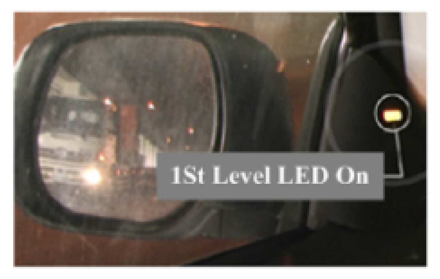
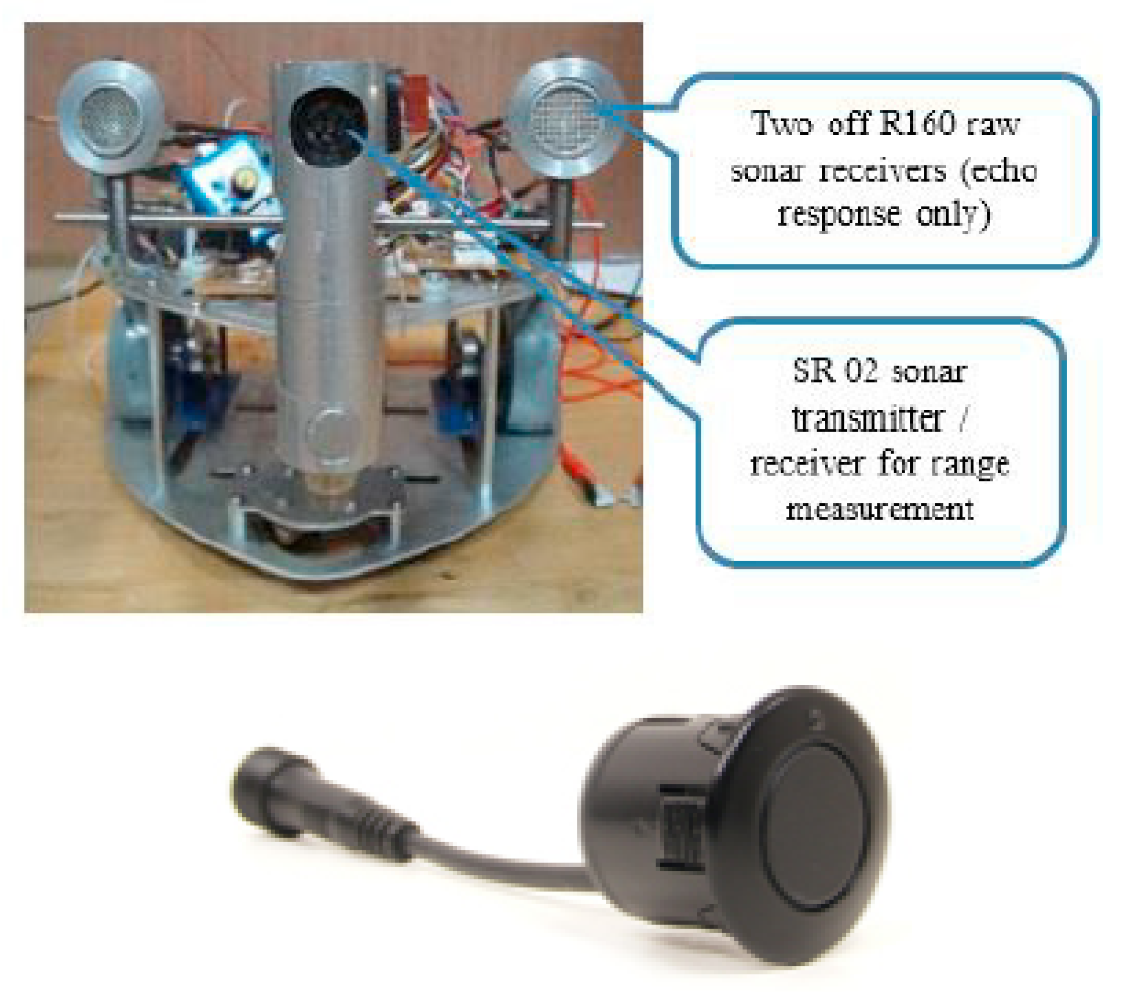
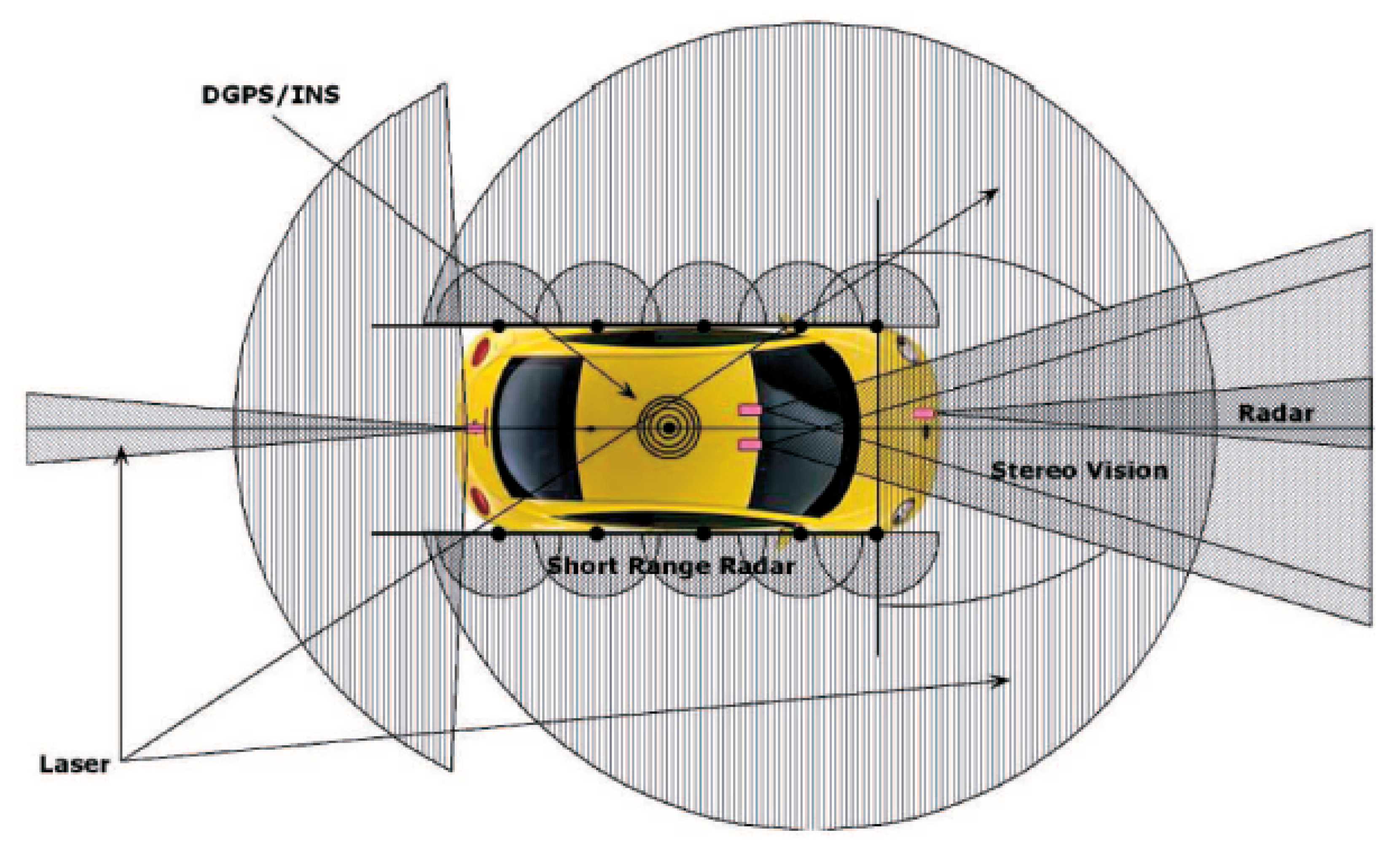
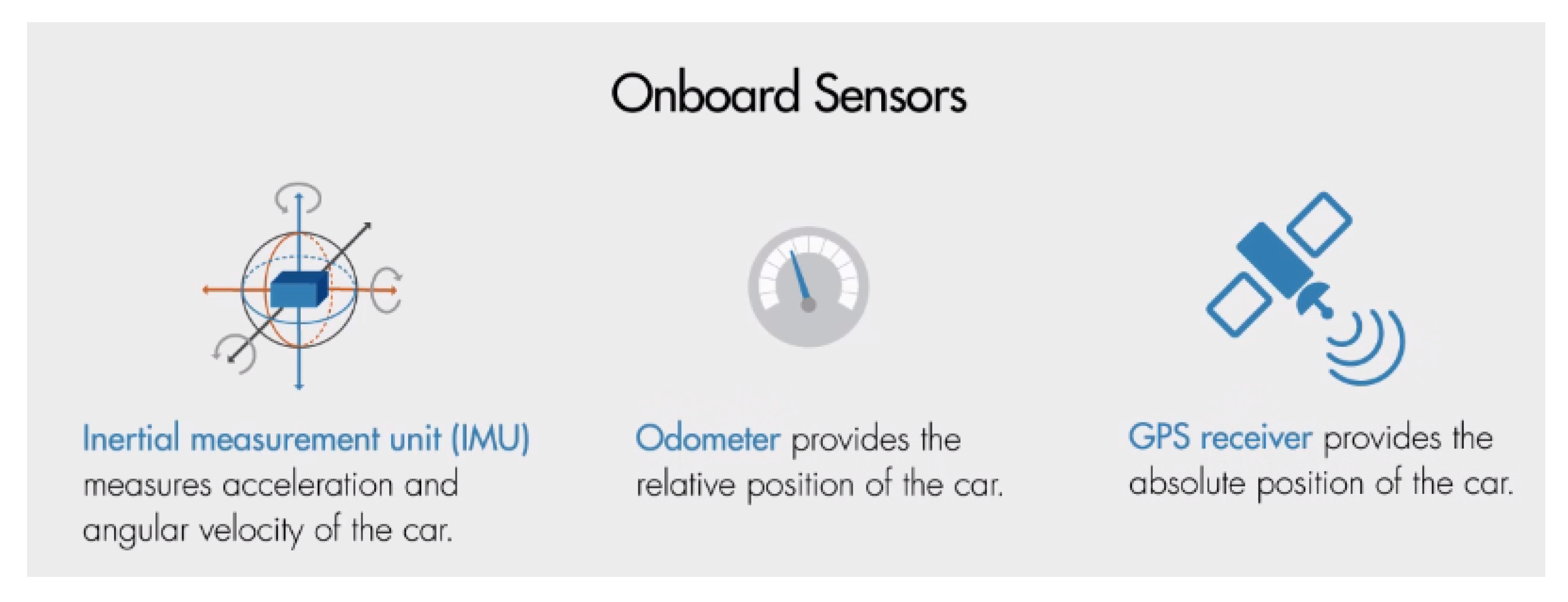
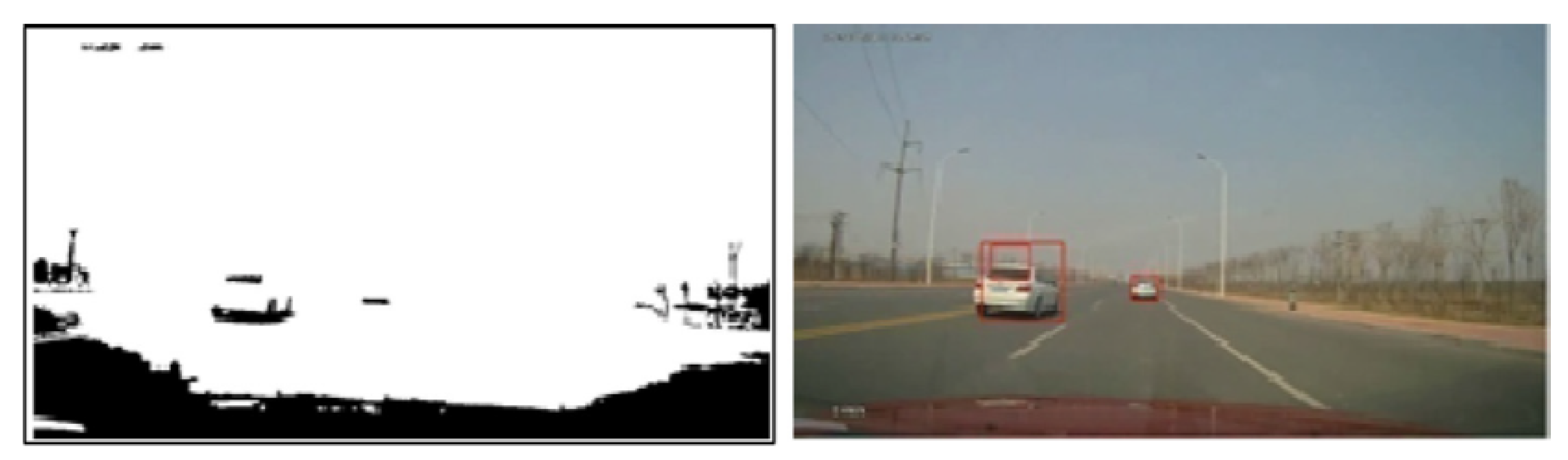
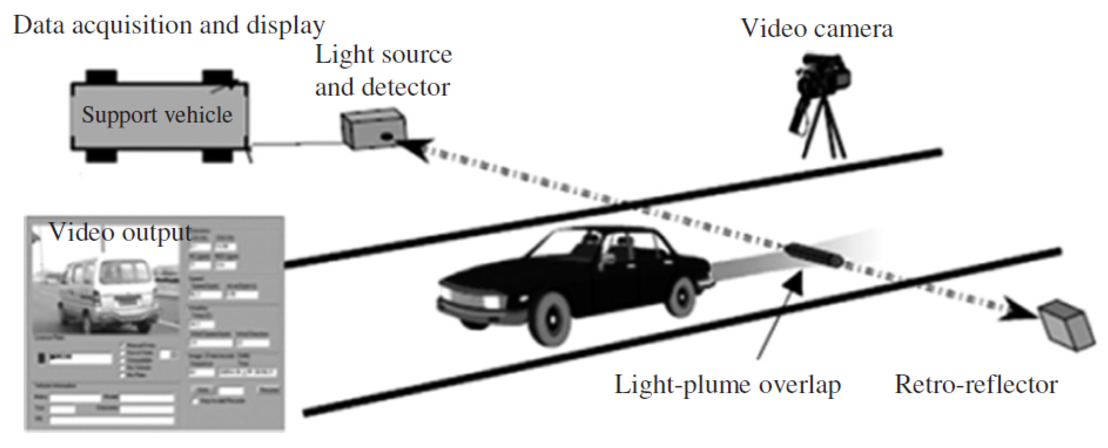
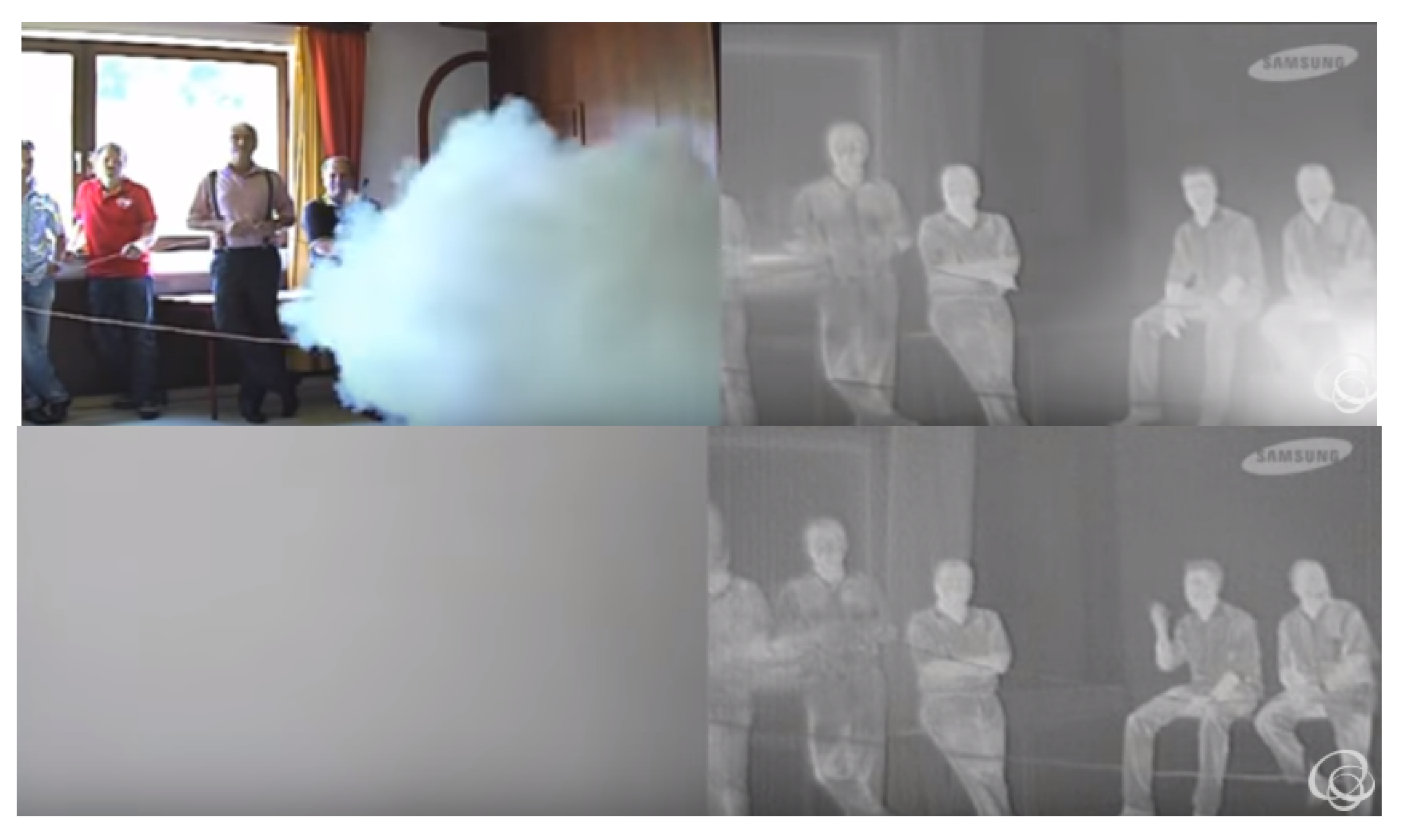
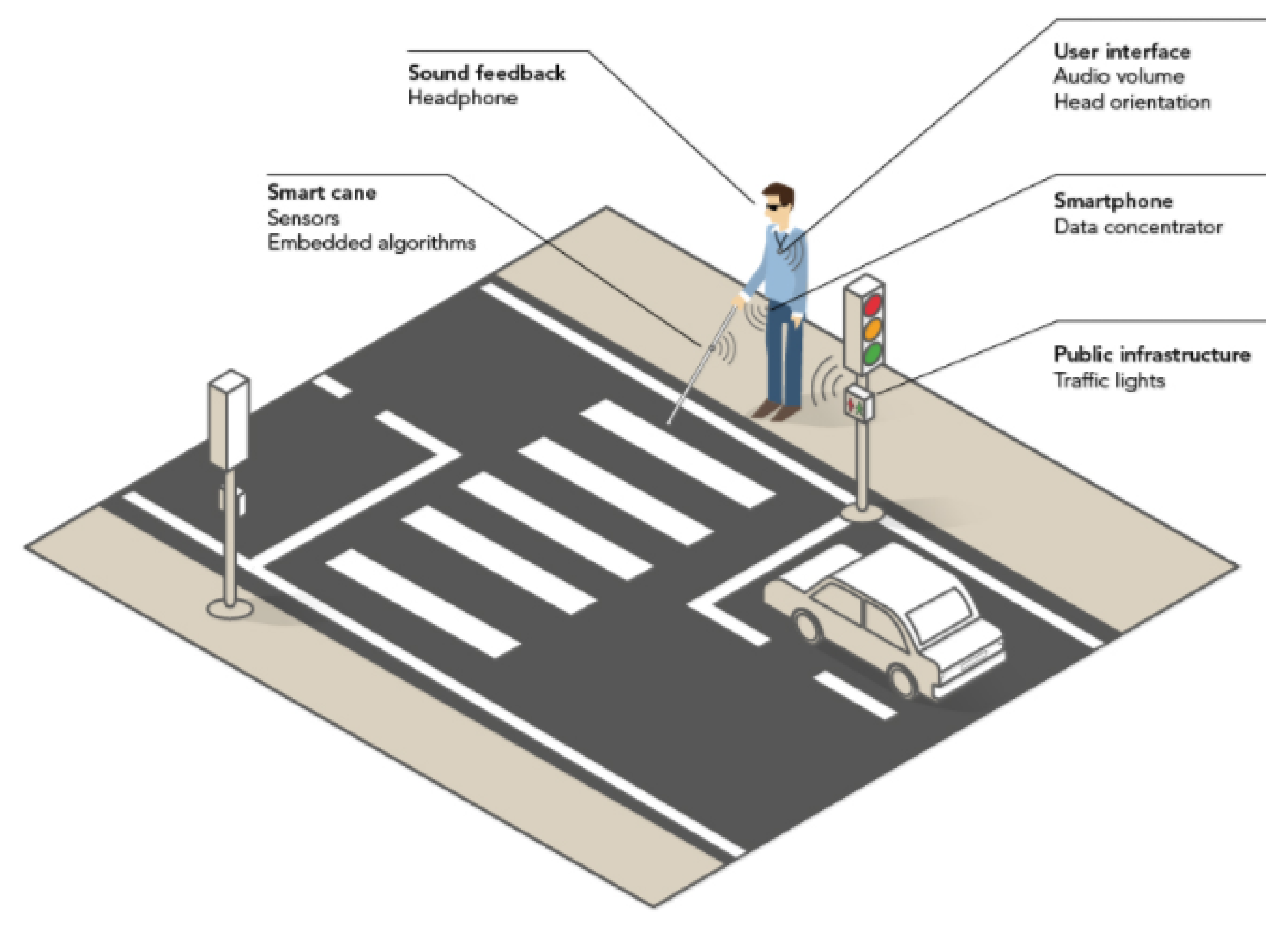
Table 1.
Luxury-brand vehicles with autonomous functions available [13].
Table 1.
Luxury-brand vehicles with autonomous functions available [13].
| Vehicles | Autonomous Freeway Driving | Autonomous Lane Change | Semi-Autonomous Parking | Semi-Autonomous Braking |
|---|---|---|---|---|
| BMW750i xDrive (BMW,2017; Sherman, 2016) | √ | √ | √ | |
| Ford (high-end production vehicles) (Company, 2014) | √ | √ | √ | |
| 2015 Infiniti Q50S (Sherman, 2016) | √ | √ | ||
| Lexus RX (Lexus, 2017) | √ | √ | ||
| Mercedes-Benz E and S-class(Sherman, 2016; Mercedes-Benz, 2013; Ulrich, 2014; Tingwall, 2013; Vanderbilt, 2012) | √ | √ | √ | |
| Otto Semi-Trucks(Stewart, 2016) | √ | √ | ||
| Renault GT Nav(Renault, 2017) | √ | √ | ||
| Tesla, Model S (Golson, 2016; Sherman, 2016) | √ | √ | √ | √ |
| Volvo XC90(Volvo, 2106) | √ | √ | √ |
© 2020 by the authors. Licensee MDPI, Basel, Switzerland. This article is an open access article distributed under the terms and conditions of the Creative Commons Attribution (CC BY) license (http://creativecommons.org/licenses/by/4.0/).
Share and Cite
MDPI and ACS Style
Yu, X.; Marinov, M. A Study on Recent Developments and Issues with Obstacle Detection Systems for Automated Vehicles. Sustainability 2020, 12, 3281. https://0-doi-org.brum.beds.ac.uk/10.3390/su12083281
AMA Style
Yu X, Marinov M. A Study on Recent Developments and Issues with Obstacle Detection Systems for Automated Vehicles. Sustainability. 2020; 12(8):3281. https://0-doi-org.brum.beds.ac.uk/10.3390/su12083281
Chicago/Turabian StyleYu, Xiaoyan, and Marin Marinov. 2020. "A Study on Recent Developments and Issues with Obstacle Detection Systems for Automated Vehicles" Sustainability 12, no. 8: 3281. https://0-doi-org.brum.beds.ac.uk/10.3390/su12083281
Note that from the first issue of 2016, this journal uses article numbers instead of page numbers. See further details here.