Detailed Assessment of Embodied Carbon of HVAC Systems for a New Office Building Based on BIM


1
Chair of Sustainable Construction, Institute of Construction and Infrastructure Management, Swiss Federal Institute of Technology (ETH), Stefano Franscini Platz 5, 8093 Zurich, Switzerland
2
Research Group Sustainable Building, Division of Building Technology, Department of Architecture and Civil Engineering, Chalmers University of Technology, 41296 Gothenburg, Sweden
*
Author to whom correspondence should be addressed.
Sustainability 2020, 12(8), 3372; https://0-doi-org.brum.beds.ac.uk/10.3390/su12083372
Submission received: 2 March 2020
/
Revised: 12 April 2020
/
Accepted: 16 April 2020
/
Published: 21 April 2020
(This article belongs to the Special Issue Integration of LCA and BIM for Sustainable Construction)
Abstract
:The global shift towards embodied carbon reduction in the building sector has indicated the need for a detailed analysis of environmental impacts across the whole lifecycle of buildings. The environmental impact of heating, ventilation, and air conditioning (HVAC) systems has rarely been studied in detail. Most of the published studies are based on assumptions and rule of thumb techniques. In this study, the requirements and methods to perform a detailed life cycle assessment (LCA) for HVAC systems based on building information modelling (BIM) are assessed and framed for the first time. The approach of linking external product data information to objects using visual programming language (VPL) is tested, and its benefits over the existing workflows are presented. The detailed BIM model of a newly built office building in Switzerland is used as a case study. In addition, detailed project documentation is used to ensure the plausibility of the calculated impact. The LCA results show that the embodied impact of the HVAC systems is three times higher than the targets provided by the Swiss Energy Efficiency Path (SIA 2040). Furthermore, it is shown that the embodied impact of HVAC systems lies in the range of 15–36% of the total embodied impact of office buildings. Nevertheless, further research and similar case studies are needed to provide a robust picture of the embodied environmental impact of HVAC systems. The results could contribute to setting stricter targets in line with the vision of decarbonization of the building sector.
1. Introduction
In 2019, the unprecedented frequency of heatwaves and temperature extremes following an increase in sea level and further biodiversity loss brought climate change to the center of attention [1,2,3]. These alarming indicators require consistent effort and drastic changes towards decarbonization of all sectors. The building sector is a key player in the fight against climate change, as it is responsible for nearly 40% of the total global CO2 emissions [4]. So far, both global and European strategies have focused on reducing the operational greenhouse gas (GHG) emissions through measures such as efficient building technologies and replacing fossil fuel-based energy carriers with renewable sources.
The global efforts towards zero operational GHG emissions shift the remaining emissions to so-called embodied carbon. Embodied carbon refers to GHG emissions that are released during the manufacturing, transportation, construction, and end of life phases of building materials. According to the UN Global Status Report, the embodied GHG emissions of the building sector are 11% of the total annual global emissions [4]. Furthermore, it has been estimated that embodied carbon in buildings can contribute up to 80% of lifetime GHG emissions for energy efficient building [5].
These developments indicate the need to assess the embodied carbon of the whole building. The importance of reducing embodied carbon is underlined in many recent studies [6,7,8,9,10,11] as well as in the most recent World Green Building Council’s report “Bringing Embodied Carbon Upfront” [12], which outlines the vision of zero operational and embodied carbon for new buildings by 2050. In the same report, the importance of life cycle assessment (LCA) as a consistent and globally accepted method to assess and communicate environmental impact through the lifecycle of the building is clearly stated and structured according to the lifecycle stages or modules defined in the widely-adopted European standard EN 15978.
In new buildings, reduction of operation energy has usually been achieved through better insulation of houses and improved technical systems [13]. The embodied energy of energy efficient buildings is usually equal to, if not higher than, a less energy efficient building, but usually, this increased embodied emission during the construction is quickly paid back during building operation [13]. However, most LCA studies have the tendency to reduce the system boundaries to the main construction materials of a building, leaving on the side the heating, ventilation, and air conditioning (HVAC) systems [14,15]. These systems are usually quite complex, made of many different materials, and it is difficult to quantify the total mass of the materials from plans as usual LCA are carried. Very few studies include detailed HVAC system calculation in their LCA [9,16,17,18].
Furthermore, despite the increasing number of LCA studies which make use of building information modelling (BIM) [19,20,21], HVAC systems are neglected. This leaves a knowledge gap regarding the embodied impact of HVAC systems and therefore a blind spot in the building’s overall embodied carbon footprint [9,16,17,18].
This study aims to provide transparency about the embodied impact of HVAC systems for a new office building in Switzerland. Therefore, detailed information is retrieved from the manufacturers and the project documentation and combined with the data extracted from the BIM model. Furthermore, through the detailed assessment, this study seeks to provide insights about the share of the different HVAC components (i.e., pipes, insulation) to the overall embodied impact of the HVAC systems. The second objective is to identify an appropriate workflow to perform an automated LCA for HVAC systems using a nearly as-built BIM model as a basis. A way to relate geometrical and environmental data coming from the HVAC manufacturers and the LCA databases to the BIM model under the scope of digitalizing and automating the LCA is proposed.
2. State of the Art of Life Cycle Assessment (LCA) of Heating, Ventilation, and Air Conditioning (HVAC) Systems and Building Information Modelling (BIM)-Based LCA
LCA has been used in many studies, mainly for residential and office buildings [11].
In recent years, BIM is increasingly used to facilitate establishing a bill of quantities of materials for the life cycle inventory (LCI) phase of LCA and reducing the amount of manual data input as shown in several recent review papers [20,22,23]. The accuracy of the LCI depends on the level of development (LOD) of the BIM model. The LOD defines the minimum content requirements for each element of the BIM at five progressively detailed levels of completeness, from LOD 100 to LOD 500 [24]. However, most papers on BIM-based LCA methods do not declare the LOD for the LCA [20].
Most studies examine the environmental impact of the structural elements and the building envelope [16]. Only a few studies focus on the impact of building services, including HVAC systems. However, there is increasing research interest in generating knowledge about the environmental impact of building services as they play a significant role in embodied carbon reduction [6,17,18]. One of the biggest challenges is that existing studies generally cannot perform a detailed assessment, mainly due to the lack of data and methods to estimate the embodied environmental impact, especially for HVAC components that are composed of various raw materials [6].
The impact of HVAC systems is usually assessed together with other building services like electrical equipment and plumbing [25,26]. It has been estimated that embodied carbon related to building services represents up to 10–12% of the total embodied carbon of a typical building [8,27]. In Switzerland, the GHG emissions during the manufacturing and maintenance of HVAC systems (heating, ventilation, heat distribution) account for about 13% of the total emissions of new office buildings [28]. However, the numbers are based on average values.
To date, only a few studies measure the embodied impact of HVAC systems [17]. Moreover, even fewer studies use BIM to assess the impact of HVAC systems [18,29,30,31]. Only one of them [31] uses an as-built or nearly as-built BIM HVAC model. None of them implement such a high level of detail as this study.
In general, there are two types of LCA studies for HVAC systems. The first type of study conducts a comparison between two or more HVAC systems, to identify which system has a smaller environmental impact, or to assess how multiple parameters such as climate, energy mix, and local policies influence the resulting environmental impact [6,7,8,16,32,33]. These studies are not interested in a detailed assessment. In most cases, they are based on generic data and assumptions. Hence, the first type of study does not relate to the scope of this study and cannot be used for comparison reasons.
The second type of LCA for HVAC refers to the detailed assessment of an HVAC system and is aligned with the scope of this research. One of the main purposes of such studies is to provide transparency of the actual impact of HVAC systems and avoid simplifications that can lead to inaccurate and misleading environmental impact calculations. In the context of this research, only four studies [7,29,30,31] have been found to follow a similar approach and are further discussed in more detail.
The study by Borg et al. [29] conducts a cradle-to-grave LCA for the ventilation system of a six-story office building in Trondheim. It uses a BIM model for the material quantity extraction, which was the basis for construction and thus very accurate, according to the authors. In terms of BIM and LCA methodology, it follows a unidirectional and fragmented process. The material information must be exported whenever changes are applied to the model (and thus the LCA calculations must be redone). The embodied impact results are based on an optimistic scenario for the European electricity supply mix and show that the impact of materials, construction, and demolition for ventilation is 33.7 kgCO2eq/m2. This information can be used for comparison reasons, although it represents only one aspect of the overall HVAC systems impact.
The second study by Dokka et al. [30], investigates a typical four-story office building in Norway modeled with BIM in order to identify the most critical parameters in the design of a zero energy building (ZEB). In terms of methodology, the material inventories are exported from the BIM model, and the calculations are performed in the LCA tool SimaPro, which is again a unidirectional and fragmented process. The total heated floor area (HFA) is 1980 m², and the lifetime of the building is set to 60 years. The total embodied emissions are approximately 8.5 kgCO2eq/m2 in annualized emissions, and the emissions due to ventilation are 0.4 kgCO2eq/m2 per year. The study does not provide insights into the embodied impact of the cooling and heating system. Finally, the authors highlight that the technical systems used in the concept model have not been properly dimensioned, and only rough estimates have been used in the embodied emission analysis. Thus, the results might deviate from the actual impact.
The study conducted by Hollberg et al. [31] follows a cradle-to-grave BIM-based dynamic LCA similar to the one used in this research. It establishes automated and bidirectional links with the model and the LCA database, allowing for continuous and real-time LCA monitoring throughout the planning phase. The LCA is done for a new office building in Switzerland. The building has an HFA of 675 m2, and the reference service life (RSL) is 60 years. The BIM model has a high level of geometry at the end of the planning phase. The results show that the interior (ceilings, doors, furniture, railings), with 43%, has the highest embodied impact on the environment, followed by 24% for technical equipment, 21% for structural parts, and 12% for envelope. This study focuses more on the LCA methodology, and the accuracy of the data used for the environmental assessment of the technical installations is unclear.
Ylmén et al. [7] use a real case study of a new office building in Sweden to perform a detailed post-construction LCA using site-specific data provided by the contractors. This LCA has a similar scope, functional unit, and boundary conditions. Although it does not use a BIM model for material quantity extraction and the LCA data were adapted to the Swedish conditions, this study can be used for benchmarking purposes. The results relevant to the global warming potential (GWP) of HVAC systems show that the production and operation phase contribute most to the overall HVAC carbon emissions, with production reaching up to 38 kgCO2eq/m2 and operation up to 100 kgCO2eq/m2. The study highlights the importance of assessing HVAC systems as they were proven to have a considerable impact, especially due to replacements.
BIM-based LCA is used in many studies as an attempt to move away from conventional LCA (manual-based calculations) and provide designers with a tool that facilitates environmental impact assessment of buildings during the design phase as well as for post-construction evaluation (i.e., for compliance with standards or for knowledge generation) [34,35,36,37].
Currently, a few commercial tools exist that combine LCA with BIM (e.g., Tally or OneClickLCA). The common practice is to extract information from the BIM model (usually in IFC or gbXML format) and later insert it into the LCA software where the assessment is performed. Another approach often suggested by researchers [38,39,40] uses BIM with a visual programming language (VPL). This method enables the automatic extraction of information from the BIM model and the creation of updatable links to LCA databases.
Although these two approaches have been used considerably, they neglect or oversimplify HVAC systems. There is a research gap in terms of embodied environmental impact but also of how to assess HVAC systems using a BIM model and the existing tools or methods.
3. Method
3.1. BIM and LCA Workflow for HVAC Systems
In general, three types of information are needed to perform the BIM-based LCA, namely geometrical data, material data (quantity and name), and LCA data. This information can be acquired from different sources. Geometrical information is extracted directly from the BIM model. Material information can be extracted directly from the BIM model. If this information is not available in the model, then product datasheets are used instead. In some cases, material quantity information can be directly retrieved from the BIM model or product datasheet. In other cases, the quantity needs to be calculated by combining mathematical formulas with geometrical information coming from the BIM model.
The integrated BIM and LCA workflow for the HVAC systems is described in Figure 1. The schematic diagram shows the different data sources that are linked to the VPL. Specifically, information from the BIM model (1), the product datasheets (2), and the LCA database (3) are combined in the VPL environment where the impact is calculated, and the results are exported in the desired format.
The BIM software used in this study is Revit 2019, and the VPL is Dynamo 2.0. The VPL serves as the basis and performs the main functions that are necessary to conduct the BIM-based LCA. These functions are:
- Directly extracting object and material data from the BIM model.
- Establishing bidirectional linking between the BIM objects and the product datasheet/catalogs and between materials and the LCA database.
- Performing LCA calculations and exporting results in an Excel file.
The flexibility of the tool makes it possible to customize the proposed workflow according to the desired (LCA) boundary conditions, the available data, as well as the data format and its structure.
3.2. Geometrical Data and Material Data
The BIM model is used as the main source for material and geometrical data. The analysis starts from the object level and refines calculations to the material level in three steps. Initially, an advanced grouping and sorting of the elements is done according to the level of complexity and the nature of the elements. For example, pipes are grouped together with the ducts because they are both linear elements and have a similar level of detail (complexity). At a second level, elements are further subdivided. For example, ducts are sub-grouped into rectangular and round ducts. The third and lowest level of grouping/sorting is done according to material type, for example, round steel ducts and round copper ducts. Four distinct groups are created according to common characteristics, namely geometry and level of complexity. These four groups are ducts and pipes, fittings, mechanical equipment and air terminals, and pipe and duct accessories.
Overall, three methods are applied for the material quantity calculations of the assessed groups. In the first method, the material and geometrical information are extracted from the BIM model, and the weight of the materials is calculated in Dynamo with the use of scientific formulas (BIM data combined with scientific formulas). In the second method, the material and geometrical information is extracted from the BIM model and combined in Dynamo with product datasheet information (BIM data combined with product datasheet data). In most cases, the weight information coming from the product datasheet is provided per object and not per material. Thus, a percentage share of the total weight to the various object materials must be assumed. The third method includes the direct mapping of objects to their weight information coming from product datasheets (BIM objects linked to product datasheets). Again, a percentage share of the total weight to the product materials must be assumed. If none of the abovementioned is applicable, as in the case of the fittings, then rule of thumb estimations are applied.
3.2.1. Ducts and Pipes
Pipes and ducts are linear elements that have width, length, and area predefined parameters in Revit. For the material quantity calculation of the steel pipes, the Equation (1) according to EN 10220: 2002 [41] is used. The material constant 0.0246615 is for steel pipes with a density of 7.85 kg/dm3.
where:
- M = mass per unit length in kg/m,
- D = specified outside diameter in mm, and
- T = specified wall thickness in mm.
Equation (2) should be used in the case of different materials (i.e., aluminum, copper). The resulting value is later multiplied with the total length of the pipes to calculate the total material quantity of the pipes. The calculation script is fully automated and generic in the sense that it can be used for any similar calculations.
where:
- OD = specified outside diameter and
- W = specified wall thickness.
The ducts belong to the same group as pipes, yet some properties such as the wall thickness, which is required to calculate the material quantity, are not included in the predefined parameters of Revit (software-related restrictions). Thus, it is not possible to calculate the weight by solely extracting information from the BIM model. To calculate the material quantity of the ducts, information from a manufacturer’s datasheet is extracted and mapped to the duct components. The mapping is performed based on the height and the width of the duct opening. Similarly, to the ducts, flex tubes are combined with the product datasheet information based on their diameter size.
The insulation type of the pipes and the ducts and its volume is extracted directly from the BIM model and multiplied with the density of the insulation material. The developed script initially extracts and groups the different types of insulation existing in the model. Then the volumes of each group are extracted and summed up to be combined with the density of the material.
3.2.2. Fittings
Fittings have complex geometry (polyhedrons). In this case, they were modelled as solid objects (no wall thickness, no openings). Furthermore, these objects had no length or area parameter, and no material was applied during the modelling phase. To calculate the weight of the fittings, first, a material is applied to their surface. Thus, it is possible to extract the surface area based on the material area. Second, the ratio of the openings to the total area is calculated for the different types of fittings (55 types). Finally, the weight of the fittings is calculated as a percentage of the total pipes and ducts weight based on area ratio, as shown in Equation (3). The resulting value was verified using empirical values.
3.2.3. Mechanical Equipment and Air Terminals
Mechanical equipment and air terminals are complex objects that can only be assessed if the necessary information from the manufacturer is provided or if the BIM object contains this information. When information is not available, similar equipment from other manufacturers is used instead.
3.2.4. Pipe and Duct Accessories
Pipe and duct accessories refers to all components that control air and water flow and pressure, such as valves and dampers. Most of these elements have a mechanical device (meter, actuator, sensor) that is operating the equipment. Like the mechanical equipment and the air terminals, these components require information from the manufacturers, or the information should be included in the BIM object. Control devices and meters contain materials such as solder alloys, TBBA, and FR-4, which are mainly part of the printed circuit boards (PCB) that cannot be found in the existing LCA databases. Therefore, they are calculated based on primary materials such as steel and brass.
3.3. LCA Data
The LCA data are retrieved from the KBOB and the Ecoinvent database. The KBOB [42] is an LCA dataset provided by the Swiss Conference of the Construction and Real Estate Organs of Public Builders (KBOB) for typical building materials in Switzerland, and it is based on Ecoinvent. The linking of the LCA values for the calculation of the embodied carbon is based on material mapping. The reason why material-based mapping is used is twofold; first, the case study model consists of around 60,000 elements. The complexity of these elements varies widely as well as the number of materials that they are composed of. In many cases, mainly mechanical equipment and air terminals, this information was not available in the provided model, and the material information had to be retrieved from the producers and inputted manually in an Excel file. Second, the LCA databases still lack a great deal of product-specific data for construction products. Thus, in many cases, similar materials must be used instead of the actual ones, ending up with 16 materials that describe the whole HVAC systems model.
To perform the material-based mapping, an Excel file was created containing information about the materials existing in the model and their LCA values, which were retrieved from the LCA database. Once the materials from the model were extracted and grouped together for the defined assessment groups (i.e., pipes and ducts, fittings, air terminals), the mapping/linking with the customized Excel LCA database was made possible in Dynamo.
3.4. Case Study
The case study is the Siemens International Headquarters office building in Switzerland. The office building was completed in 2018 and is part of the new Siemens campus in Zug. It has a LEED platinum certification and the Swiss Minergie label, which focuses on the building shell and energy consumption. The building consists of seven floors and has a gross floor area (GFA) of 32,000 m2, including two underground floors, which are used mainly as a garage. In terms of HVAC systems, the building runs on water to water heat pumps and uses water from lake Zug for heating and free cooling purposes.
This is one of the first Siemens construction projects to use BIM. The BIM model for the HVAC systems (Figure 2) has undergone extensive revisions after the completion of the construction. It has a level of development (LOD) above 300, although it was observed that some elements were more detailed than others. Furthermore, the project was well documented including product datasheet and detailed information for most of the HVAC equipment. It can be said that the post-construction BIM model combined with manufacturer’s information fulfils as-built requirements.
In terms of LCA, a cradle-to-grave analysis is conducted for HVAC products and services, and the system boundary is based on the lifecycle modules defined in EN 15804 [43]. The modules assessed in the study are A1–A3 (fabrication), B4 (replacement), B6 (operation), and C1–C3 (disposal). The rest of the modules were kept out of the scope of this study due to a lack of relevant data. The reference unit was set to 1 m2 AE to comply with the Swiss standards for planning and construction. According to SIA 380/1 2016 [44], the AE stands for the energy reference area, which is the sum of all over- and underground floor areas that lie within the thermal building envelope and are heated or air-conditioned. The energy reference area equals the heated floor area and is 22,000 m2. The reference study period is 60 years, as defined in SIA 2032 [45]. The replacement frequency of the equipment is estimated using combined information from manufacturers and the ASHRAE standard. These estimations are based on a most-likely scenario. This study focuses on the impact of HVAC systems with regards to climate change. For this reason, global warming potential (GWP) is used to quantify the GHG emissions in units of CO2-equivalent.
4. Results
4.1. Material Quantities
The implemented customized workflows, as well as the various groups and the materials used to perform the BIM-based LCA, are summarized in Table 1. It is concluded that the more complex the BIM objects, the higher the dependency on the manufacturer’s information. This is inversely proportional to the flexibility of the tool.
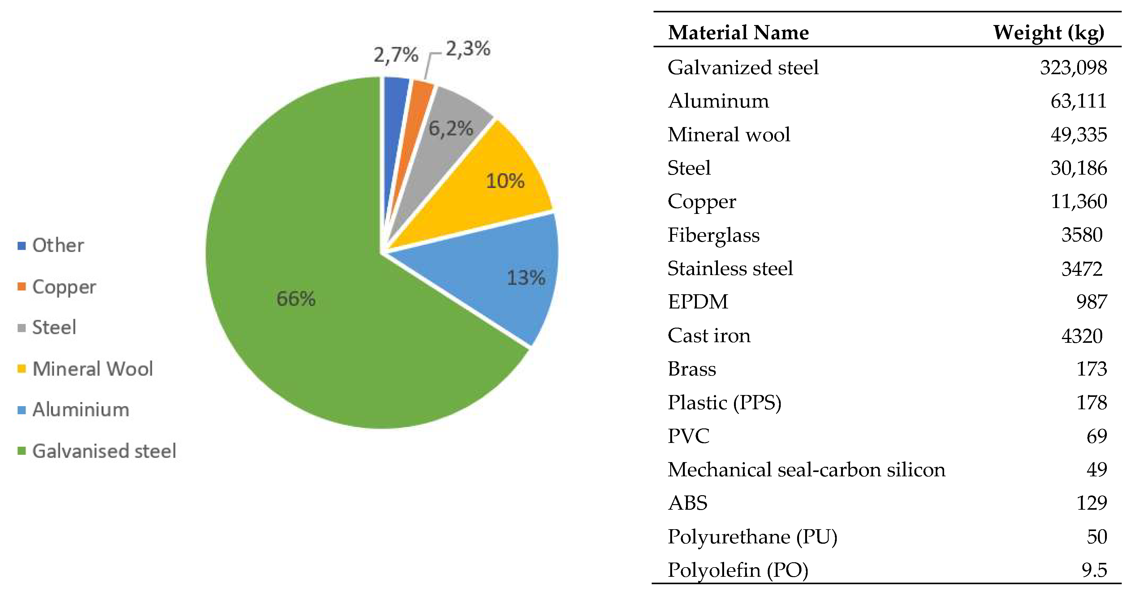
The results from the material quantity extraction show that galvanized steel (66%), aluminum (13%), and mineral wool (10%) are the prevailing materials. As expected, steel is the most common material found in HVAC equipment, coming primarily from the pipes and the ducts, which are heavy elements used for water and air distribution. The total amount of steel, including galvanized steel, stainless steel, and steel, is 356 tons, which correspond to about 80% of the total material quantity (Figure 3).
4.2. LCA Results per Component
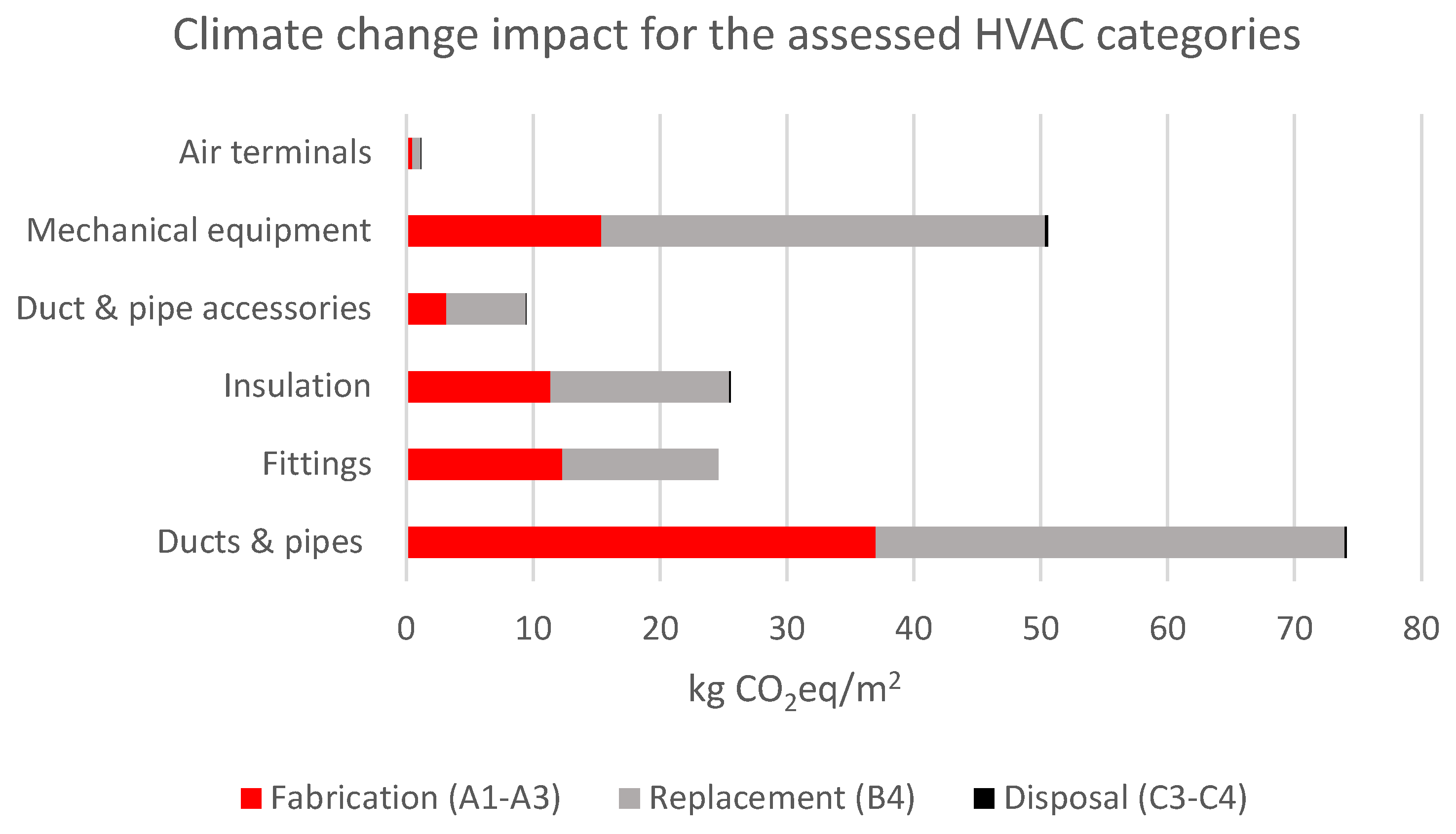
These results become more intriguing when the whole life cycle of the building is considered, as the replacement of ductwork and mechanical equipment takes place. The resulting GHG emissions in the replacement phase show that the impact of the mechanical equipment, the air terminals, and the insulation is increased compared to the manufacturing phase (Figure 4). The impact of the mechanical equipment is almost doubled during the use phase (35 kgCO2eq/m2) compared to its fabrication impact (15.3 kgCO2eq/m2). This increase is related to the frequency of the equipment replacement during the building’s use phase. For example, heat pumps are replaced every 20 years. Subsequently, they are replaced twice during the 60-year building’s lifetime. The quantity of the material has an immediate effect on the resulting environmental impact, which in the case of the heat pump, would be double the fabrication impact. Overall, it is concluded that the mechanical equipment, together with the ducts and pipes, are the main contributors to the total lifecycle GHG emissions of the HVAC systems.
At a higher level, results about the investigated modules show that replacement (B4) with 1.70 kgCO2eq/m2 annualized emissions is the most carbon-intensive building lifecycle stage, while fabrication (A1–A3) with 1.32 kgCO2eq/m2 annualized emissions, and operation (B6) with 1.25 kgCO2eq/m2 annualized emissions and are of similar importance. The operational impact calculations were based on energy consumption data from the utility company combined with the as-planned energy distribution diagrams from the energy engineer. The energy consumption of HVAC systems accounts for 57% of total energy consumption. The disposal impact is very little (0.4 kgCO2eq/m2) coming mainly from insulation and secondary materials.
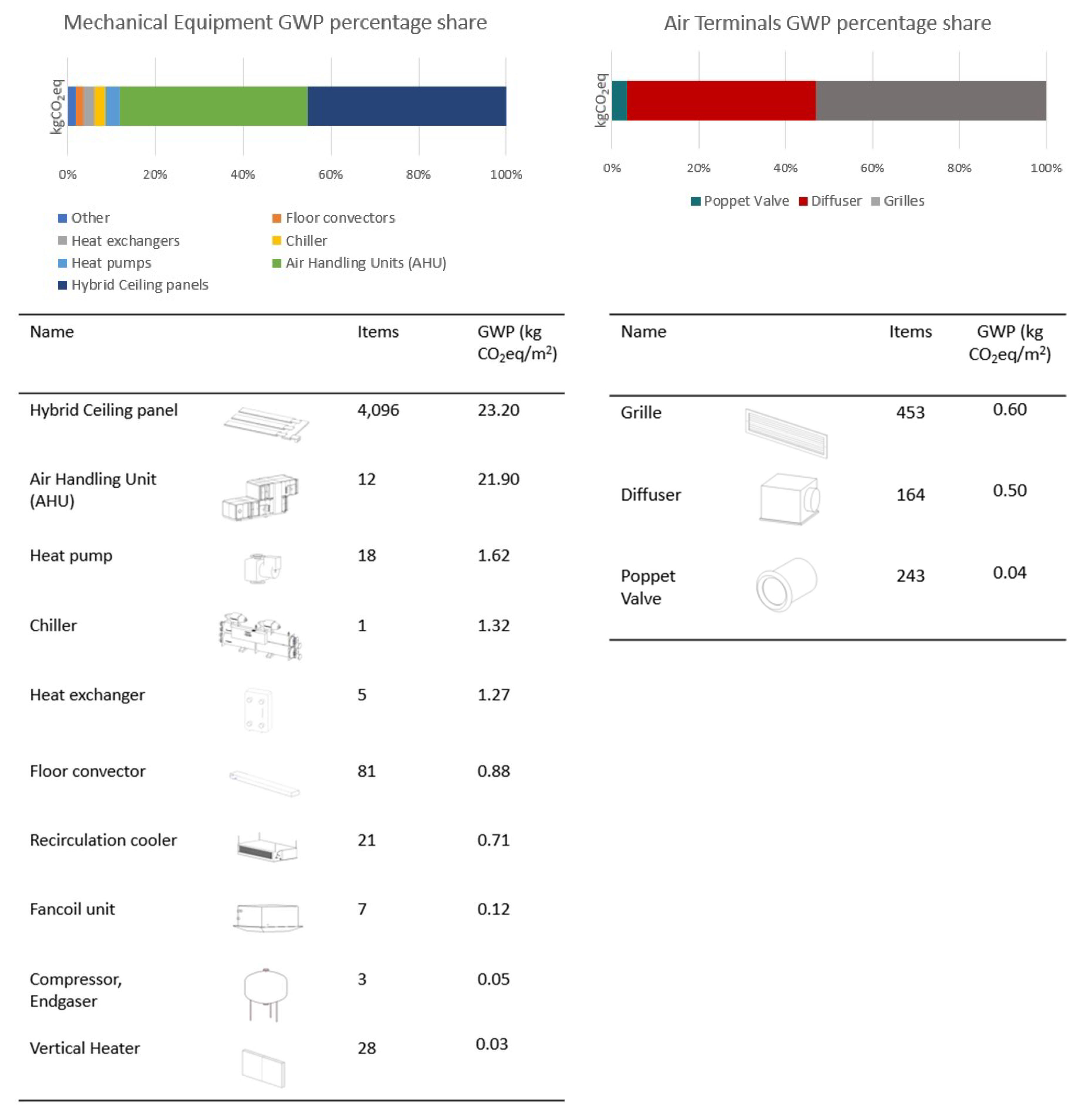
A critical finding of this study is that it is worth investigating the amount and the impact of the air filters existing in the HVAC equipment. According to the maintenance instructions for the case study building, the filters should be replaced at least once per year during the 60-year service life of the building. For the big air handling units (AHU), which are part of the mechanical equipment (Figure 5), this amount becomes considerable. Filters are responsible for 65% of the total replacement impact of the AHUs. When looking at the whole HVAC system, the total impact coming from the filters during the use phase of the building amounts to 11% of the total replacement impact.
The various components of the mechanical equipment and the air terminals are shown in Figure 5. Among the mechanical equipment components, the hybrid ceiling panel is the most recurrent component and has the highest impact of 23.2 kgCO2eq/m2. Very close, with 21.9 kgCO2eq/m2, are the AHUs, which are massive blocks of equipment containing, among other air filters, heat exchangers, fans, and air coolers. The rest of the elements have around 95–99% fewer emissions. It is noteworthy that the emissions of one chiller are comparable to the emissions of 18 small-sized heat pumps. The air terminal components have a minimal impact, with no significant variations among the impact of the different component types.
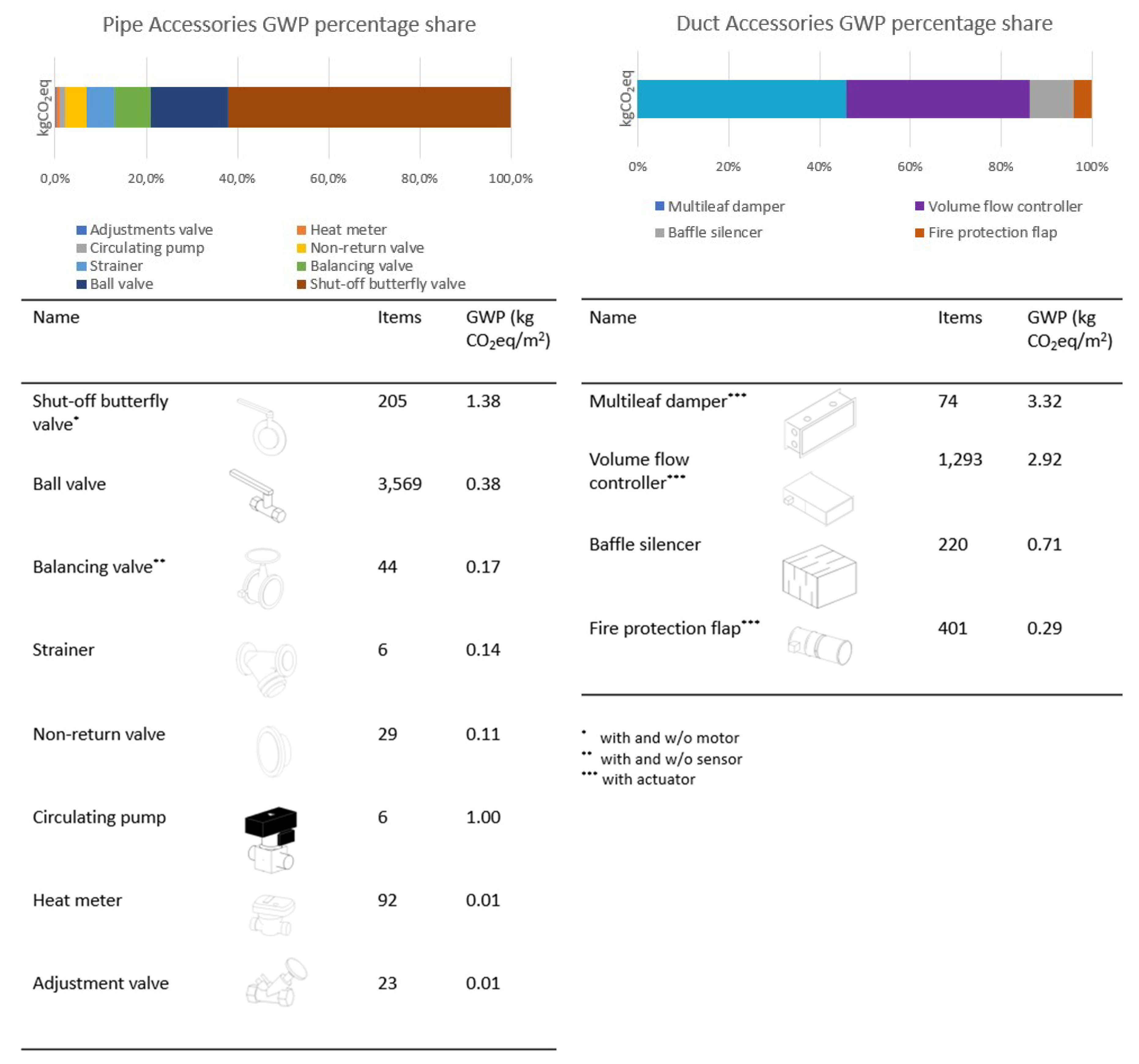
Accordingly, Figure 6 shows the components that belong to the pipe and duct accessories. It is shown that while the pipes have more types and a higher number of components, their overall GWP is only one-third of the ducts. This is mainly since the duct components are bigger and thus have more material. Among the pipe components, the butterfly shut-off valve has the highest impact of 1.38 kgCO2eq/m2. From the duct accessories, the multi-leaf dampers and volume flow controllers are the most emission-intensive elements.
4.3. Comparison to Benchmarks
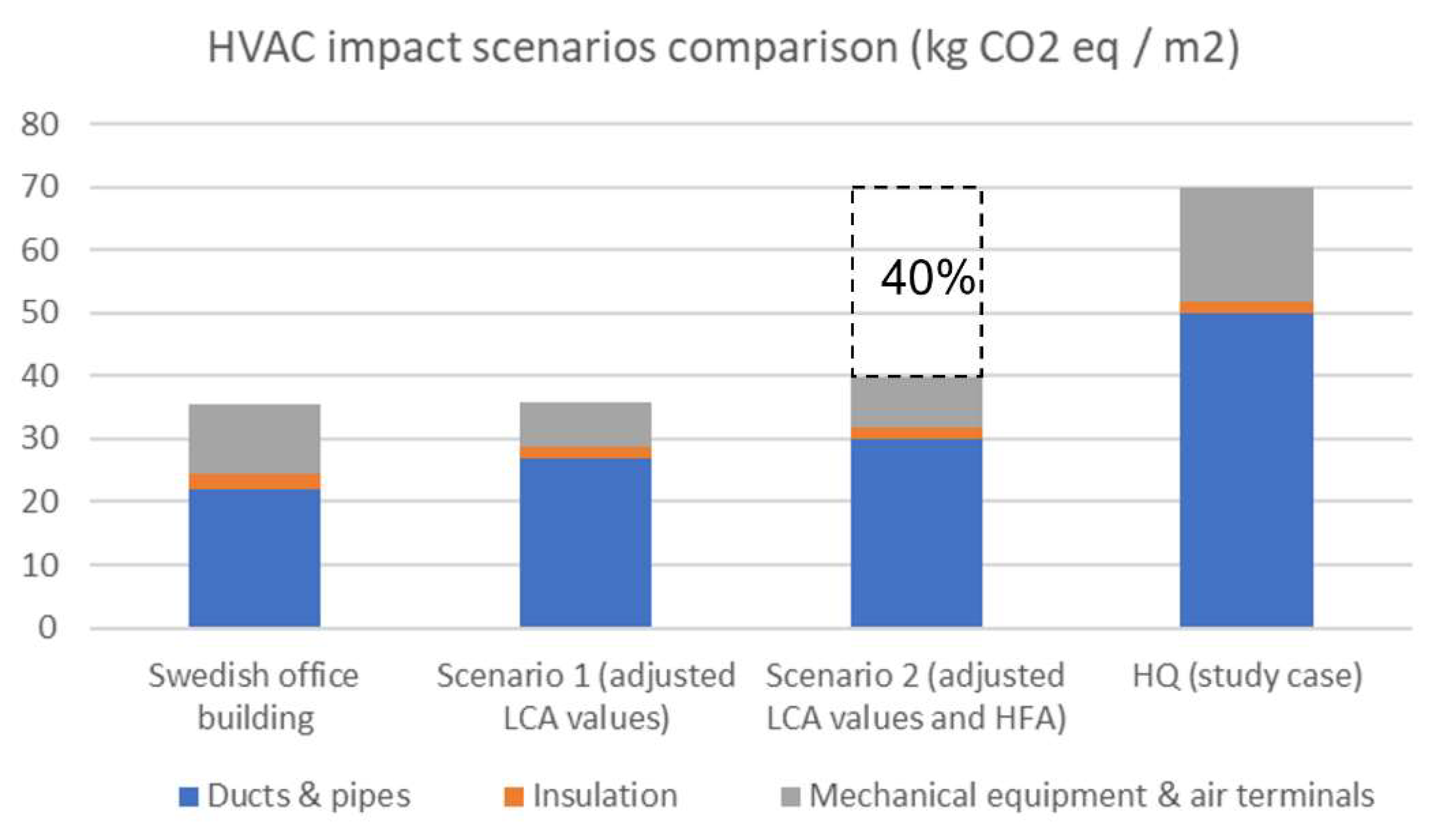
The resulting GWP due to fabrication are compared to a similar case study in the Swedish context [7]. The two case studies are implemented for the new office building and have a similar LCA scope and boundary conditions. Nevertheless, the calculations are adjusted to country-specific conditions. To account for uncertainty, two scenarios are developed investigating how country-specific parameters, namely LCA values and HFA, can affect the resulting values measured in kgCO2eq/m2. The categories compared are ducts and pipes (ductwork and pipework), insulation (only mineral wool), and mechanical equipment and air-terminals. In the first scenario (Scenario 1), the same LCA values as in the Swiss case study of the Siemens International Headquarters office building (HQ) are applied to the Swedish case study. It is shown that the LCA values have only a minor effect on the total fabrication impact. However, there are differences in the share of the impact among the different HVAC categories (Figure 7). In the second scenario (Scenario 2), the HFA for the Swedish case is assumed according to the Swiss building regulations. The Swedish HFA is defined as the total floor area that is heated to at least 10 degrees Celsius, excluding outer walls. Adjusting the HFA to Swiss conditions was done using the method and the factors proposed in [46]. It is shown that the adjusted HFA does not differ a lot from the Swedish HFA, and thus the difference between Scenario 2 and the HQ base-case remains quite high. Specifically, there is a 40% deviation in the total emissions, with the pipes and ducts being the main contributors to this difference. This can be attributed to the use of different HVAC systems and distribution networks, as well as to quantities miscalculations and assumptions that were made due to lack of data.
Benchmark values from the SIA 2040 technical book are used to assess the resulting GWP impact against Swiss norms. SIA 2040 sets target values towards a 2000 watts society by defining intermediate goals for 2050 [47]. The embodied GHG emissions for the 2050 efficient scenario are 8.5 kgCO2eq/m2 a. According to [28] which is based on the SIA 2040 technical book, the shares of heating, ventilation, and heat distribution impact on the total embodied GHG of new office buildings is 13%. Therefore, it can be concluded that the SIA 2040 target for HVAC systems is about 1.1 kgCO2eq/m2a. The embodied GHG emissions of the HVAC systems for this case study are 3.05 kgCO2eq/m2a, which is almost three times higher than the SIA 2040 emissions target.
Finally, the results are framed in the context of whole building lifecycle carbon emissions. For this reason, information from many studies on the embodied carbon emissions of office buildings was considered. The draft of the Royal Institution of Chartered Surveyors (RICS) “Practitioner’s Guidance to Whole Life Carbon Assessments” [5] shows that the embodied impact of buildings can vary a lot (400–1000 kgCO2eq/m2) depending on the building type, even by a factor of two with the highest values corresponding to highly serviced areas (i.e., hospitals, high rise apartments). For the specific case of office buildings, the information paper [10] summarizes embodied carbon case studies that were conducted from different companies. It is summarized that embodied impact for offices can range between 500 kgCO2eq/m2 and 1200 kgCO2eq/m2. The total embodied impact for the HVAC systems of this case study is 183 kgCO2eq/m2. Compared to the existing knowledge for the total embodied impact of office buildings, the HVAC embodied impact would be in the range of 15–36%, which is significantly higher than previous studies and estimations.
5. Discussion
The proposed workflow allows automating the LCA by establishing links between the databases and the BIM model in the VPL environment. The responsive design of the tool enables real-time tracking of the environmental impact when changes are applied to the BIM model or the linked information. Furthermore, linking information instead of inputting data in the BIM objects solves the problem of creating “heavy” and inoperable BIM models.
The developed approach focuses on the material data collection for the LCA. Different methods for HVAC material quantity calculations are implemented based on the information existing in the BIM objects. It is shown that the flexibility of the tool depends on data availability and object geometrical complexity. Thus, the pipes and the ducts which have a simple geometry allow for multiple ways of calculation of their weight, and subsequently, their environmental impact. On the contrary, for mechanical equipment such as heat pumps, which are complex objects and consist of multiple components, it is not possible to calculate their weight based on the BIM model unless the object is modelled as 1-1 representation or if this information is included as an object property.
The realistic BIM objects are usually provided by the manufacturers and then imported into the model. When the BIM object is not provided, it can be modelled by the designer as a placeholder (rough geometry). A placeholder, although it is not an accurate geometrical representation of the product, can carry detailed information which can be shown as object properties. In this study case, the level of geometry of the equipment was varying as well as the level of information attached to the BIM objects. The post-construction BIM model has a LOD of 300 which alone does not fulfil the requirements of a detailed LCA. Most objects had a generic name (i.e., shut-off valve with motor), the dimensions, and occasionally the material name and the name of the manufacturer. Hence, a lot of effort had to be put into looking through the project documentation to identify the products, or the information had to be acquired directly from the producers. It should be noted that the quality of the material data retrieved from the various data sources can affect the accuracy of the resulting impact.
Data challenges other than the level of development of the BIM model, refer to deficient or outdated LCA databases and the accuracy and granularity of the data provided by the manufacturers. A critical point for the success of the proposed method is to have the data in an appropriate format. Currently, most manufacturers provide their product information in PDF format. Adding to that, very few give information about the impact of their products. Especially for highly sophisticated manufactured equipment such as HVAC systems, access to machine-readable data is vital; otherwise, the proposed process could never be truly automated.
In the context of this study, all the files were stored and processed locally (PC). Moreover, the data were extracted directly from the BIM model that was created in Revit software. In the future, this “isolated” approach would be very limiting and not serving the complex tasks arising from AEC processes, which are characterized by high collaboration among all the involved parties (architects, engineers, contractors, etc.), processes integration, and cross-platform flow of information.
The major limitation of extracting information directly from the BIM model or performing the LCA within the BIM software is that the language can only be read and understood by this specific software and its users. For example, Revit categories and families are not used outside the Revit environment. Hence, interoperability can only be achieved within the Revit environment and the relevant Autodesk solutions. Nevertheless, most BIM software offers the possibility to export data in IFC (Industry Foundation Classes) format, making it possible to share information across the entire BIM ecosystem in a consistent and repeatable way. LCA databases should also be represented in a common data format like IFC in order to be reusable and understood by other software and users. Using the proposed tool to link building data to product LCA data based on open standard formats can enable enormous possibilities for the future of LCA, such as generating consistent knowledge regarding buildings and building products, providing transparency of processes among all involved project parties, and finally contributing to the improvement of existing LCA databases.
In terms of the LCA, the results show that the embodied impact of the case study is three times higher compared to the SIA 2040 embodied carbon target values for HVAC systems. This finding raises the question of whether SIA 2040 is underestimating the impact of HVAC systems or this difference is due to the high complexity of smart buildings. The former would imply that buildings should consider a higher embodied impact for HVAC systems, while the latter indicates that as the buildings become “smarter” and thus more energy-efficient, their embodied impact increases. In this case, the GHG savings as a result of the increased energy efficiency should be compared to the added material impact to understand the trade-offs between them. Further research is required to adequately address this question and understand the contribution of the HVAC systems to the embodied impact of new office buildings.
The presented study assessed HVAC control devices wherever this was possible. However, these devices include components such as printed circuit boards and transducers, which consist of materials with unknown impact. This hinders the detailed assessment of these elements. Furthermore, for this study, only information about the devices (motors, meters, actuators) of the duct and pipe accessories were available. Therefore, an assessment that includes all the HVAC electronic components could reveal their actual contribution to the impact and would eventually shift the impact even more towards the material side.
Noteworthy is the impact of the HVAC filters. The replacement frequency of the filters is high compared to the rest of the equipment. Thus, it makes sense to study their environmental footprint during the lifetime of the building. In this study only fiberglass was considered for the calculation of the filter impact, and only for the equipment that this information was available. Despite data limitations, it is shown that the replacement impact of the filters is substantially high compared the total HVAC replacement impact. Until now, LCA studies tend to overlook the filters’ impact, which, according to the results of this study, is not insignificant, especially in the case of big commercial and office buildings.
Finally, it is crucial to define the data requirements for each BIM model even before the design phase and make sure that the requirements fulfil the project objectives. Pinpointing the end-use of the model is critical. For example, if the model is used for energy optimization, the data relevant for the optimization process must be inputted or linked to the model. One project might serve more than one purpose. This is not a problem if the requirements for each end-use are clearly defined and as long as the model can stay “lightweight” and operable. This can always be achieved by linking the information instead of inputting data at the BIM object level, as described in the proposed workflow.
6. Conclusions
This study focuses on the detailed environmental assessment of HVAC systems using BIM and proposes an integrated method to perform a complete LCA. The method is based on the following three functions: (a) Directly extracting object data from the BIM model; (b) establishing bidirectional links between BIM objects and product datasheets, and between materials and LCA databases; and (c) calculating the embodied carbon and exporting data. The application to a case study shows that the tool is flexible and can be adjusted/extended according to the available data. However, the more complex the objects, the less flexible and the more vendor dependent the tool becomes. It is concluded that using this or similar tools can enable transparency for the impact of HVAC systems in all stages of the building lifecycle.
The LCA results show that the embodied impact for the HVAC system is three times higher than the targets provided by SIA 2040. Although SIA targets that are based on a global factor and the heated floor area of the building seem to work as a tool to assess the impact of the HVAC system, they do not allow to reduce the impact by optimizing the HVAC system towards embodied carbon. The proposed approach allows for the first time to compare different variants in detail and empowers designers to perform product comparisons, identify hot spots in their HVAC design, and make environmentally conscious decisions.
Nevertheless, more research is needed to determine the environmental impact of different kinds of HVAC systems. Once this knowledge is generated, current embodied carbon targets should be reviewed, and the necessity of setting stricter targets should be assessed against the 2050 vision of net-zero embodied carbon.
Author Contributions
Conceptualization, all; methodology, A.H., G.H.; formal analysis, C.K.; writing—original draft preparation, C.K.; writing—review and editing, all; supervision, A.H., G.H. All authors have read and agreed to the published version of the manuscript.
Funding
This research received no external funding
Conflicts of Interest
The authors declare no conflict of interest.
References
- NOAA National Centers for Environmental Information. State of climate: Global Climate Report for March 2019. Available online: https://www.ncdc.noaa.gov/sotc/global/201903 (accessed on 7 December 2019).
- IPCC. Global Warming of 1.5 C. An IPCC Special Report on the Impacts of Global Warming of 1.5 C above Pre-Industrial Levels and Related Global Greenhouse Gas Emission Pathways, in the Context of Strengthening the Global Response to the Threat of Climate Change. 2018. Available online: https://www.ipcc.ch/sr15/download/ (accessed on 20 November 2019).
- Nunez, S.; Arets, E.; Alkemade, R.; Verwer, C.; Leemans, R. Assessing the Impacts of Climate Change on Biodiversity: Is below 2 °C Enough? Clim. Chang. 2019, 154, 351–365. [Google Scholar] [CrossRef] [Green Version]
- International Energy Agency and the United Nations Environment Programme. Towards a Zero-Emission, Efficient and Resilient Buildings and Construction Sector; 2018 Global Status Report; 2018; Available online: https://www.worldgbc.org/sites/default/files/2018%20GlobalABC%20Global%20Status%20Report.pdf (accessed on 25 November 2019).
- Royal Institution of Chartered Surveyors (RICS). Whole Life Carbon Assessment for the Built Environment; Royal Institution of Chartered Surveyors (RICS): London, UK, 2017. [Google Scholar]
- Medas, M.; Cheshire, D.; Cripps, A.; Connaughton, J.; Peters, M. Reducing Uncertainty in Predicting Embodied Energy of HVAC Systems. In Proceedings of the ASHRAE Annual Conference, St. Louis, MO, USA, 25–29 June 2016. [Google Scholar]
- Ylmén, P.; Peñaloza, D.; Mjörnell, K. Life Cycle Assessment of an Office Building Based on Site-Specific Data. Energies 2019, 12, 2588. [Google Scholar] [CrossRef] [Green Version]
- Hitchin, R. Embodied Carbon and Building Services; CIBSE Research Report; 2013; Available online: https://www.cibse.org/knowledge/knowledge-items/detail?id=a0q20000008I754AAC (accessed on 10 December 2019).
- Alwan, Z.; Jones, P. The Importance of Embodied Energy in Carbon Footprint Assessment. Struct. Surv. 2014, 32, 49–60. [Google Scholar] [CrossRef]
- Clark, D. Information Paper—12: Embodied Carbon in Case Studies for Office Buildings. 2013. Available online: https://cundall.com/Cundall/fckeditor/editor/images/UserFilesUpload/file/WCIYB/IP-12%20-%20Embodied%20carbon%20case%20studies%20for%20office%20buildings.pdf (accessed on 13 October 2019).
- Röck, M.; Ruschi, M.; Saade, M.; Balouktsi, M.; Nygaard, F.; Birgisdottir, H.; Frischknecht, R.; Habert, G.; Lützkendorf, T. Embodied GHG Emissions of Buildings—The Hidden Challenge for Effective Climate Change Mitigation. Appl. Energy 2020, 258, 114107. [Google Scholar] [CrossRef]
- World Green Building Council. Bringing Embodied Carbon Upfront. 2019. Available online: https://www.worldgbc.org/news-media/bringing-embodied-carbon-upfront (accessed on 5 November 2019).
- Sartori, I.; Hestnes, A.G. Energy Use in the Life Cycle of Conventional and Low-Energy Buildings: A Review Article. Energy Build. 2007, 39, 249–257. [Google Scholar] [CrossRef]
- Ortiz, O.; Castells, F.; Sonnemann, G. Sustainability in the Construction Industry: A Review of Recent Developments Based on LCA. Constr. Build. Mater. 2009, 23, 28–39. [Google Scholar] [CrossRef]
- Hoxha, E.; Jusselme, T. On the Necessity of Improving the Environmental Impacts of Furniture and Appliances in Net-Zero Energy Buildings. Sci. Total Environ. 2017, 596, 405–416. [Google Scholar] [CrossRef]
- Tan, A.J.; Nutter, D.W. CO2e Emissions from HVAC Equipment and Lifetime Operation for Common U.S. Building Types. J. Energy 2011, 2, 415–426. [Google Scholar]
- Passer, A.; Kreiner, H.; Maydl, P. Assessment of the Environmental Performance of Buildings: A Critical Evaluation of the Influence of Technical Building Equipment on Residential Buildings. Int. J. Life Cycle Assess. 2012, 17, 1116–1130. [Google Scholar] [CrossRef]
- Medas, M.; Cripps, A.; Connaughton, J.; Peters, M. Towards BIM-Integrated, Resource-Efficient Building Services. In Proceedings of the CIBSE Technical Symposium, London, UK, 16–17 April 2015. [Google Scholar]
- Galiano-garrigós, A.; García-figueroa, A.; Rizo-maestre, C.; González-avilés, Á. Evaluation of BIM Energy Performance and CO2 Emissions Assessment Tools: A Case Study in Warm Weather Case Study in Warm Weather. Build. Res. Inf. 2019, 47, 787–812. [Google Scholar] [CrossRef]
- Soust-verdaguer, B.; Llatas, C.; García-martínez, A. Critical Review of Bim-Based LCA Method to Buildings. Energy Build. 2017, 136, 110–120. [Google Scholar] [CrossRef]
- Antón, L.Á.; Díaz, J. Integration of LCA and BIM for Sustainable Construction. World Acad. Sci. Eng. Technol. Int. J. Soc. Educ. Econ. Manag. Eng. 2014, 8, 1356–1360. [Google Scholar]
- Chong, H.Y.; Lee, C.Y.; Wang, X. A Mixed Review of the Adoption of Building Information Modelling (BIM) for Sustainability. J. Clean. Prod. 2017, 142, 4114–4126. [Google Scholar] [CrossRef] [Green Version]
- Eleftheriadis, S.; Mumovic, D.; Greening, P. Life Cycle Energy Efficiency in Building Structures: A Review of Current Developments and Future Outlooks Based on BIM Capabilities. Renew. Sustain. Energy Rev. 2017, 67, 811–825. [Google Scholar] [CrossRef] [Green Version]
- AIA. Document E203TM—Building Information Modeling and Digital Data Exhibit. The American Insitute of Architects. 2013. Available online: https://www.aiacontracts.org/contract-documents/19026-building-information-modeling-and-digital-data-exhibit (accessed on 15 April 2020).
- Hoxha, E.; Habert, G.; Lasvaux, S.; Chevalier, J.; Le Roy, R. Influence of Construction Material Uncertainties on Residential Building LCA Reliability. J. Clean. Prod. 2017, 144, 33–47. [Google Scholar] [CrossRef]
- Lasvaux, S.; Lebert, A.; Achim, F.; Grannec, F.; Hoxha, E.; Nibel, S.; Schiopu, N.; Chevalier, J. Towards Guidance Values for the Environmental Performance of Buildings: Application to the Statistical Analysis of 40 Low-Energy Single Family Houses’ LCA in France. Int J Life Cycle Assess 2017, 22, 657–674. [Google Scholar] [CrossRef]
- Hoxha, E.; Habert, G.; Chevalier, J.; Bazzana, M.; Le Roy, R. Method to Analyse the Contribution of Material’s Sensitivity in Buildings’ Environmental Impact. J. Clean. Prod. 2014, 66, 54–64. [Google Scholar] [CrossRef]
- Jakob, M.; Catenazzi, G.; Forster, R.; Egli, T.; Kaiser, T.; Looser, R.; Melliger, M.; Nägeli, C.; Reiter, U.; Soini, M.; et al. Erweiterung des Gebäudeparkmodells Gemäss SIA-Effizienzpfad Energie; TEP Energy und Lemon Consult i.A. Bundesamt für Energie (BFE): Bern, Switzerland, 2016; Available online: https://www.tep-energy.ch/docs/2016_GEPAMOD_GPM_SIA_Effizienzpfad_Schlussbericht.pdf (accessed on 15 October 2019).
- Borg, A.A. The Environmental Impact of Ventilation Systems in a Norwegian Office Building from a Life Cycle Perspective. Master’s Thesis, Norwegian University of Science and Technology, Trondheim, Norway, 2016. [Google Scholar]
- Dokka, T.H.; Kristjansdottir, T.F.; Time, B.; Mellegård, S.E.; Haase, M.; Tønnesen, J. A Zero Emission Concept Analysis of an Office Building; ZEB Project Report; 2013; Available online: https://core.ac.uk/download/pdf/154669884.pdf (accessed on 10 October 2019).
- Hollberg, A.; Genova, G.; Habert, G. Evaluation of BIM-Based LCA Results for Building Design. Autom. Constr. 2019, 109, 102972. [Google Scholar] [CrossRef]
- Li, M. Life Cycle Assessment of Residential Heating and Cooling Systems in Minnesota: A Comprehensive Analysis on Life Cycle Greenhouse Gas (GHG) Emissions and Cost-Cost Effectiveness of Ground Source Heat Pump (GSHP) Systems Compared to the Conventional Gas Furnace and Air Conditioner System. Master’s Thesis, University of Minnesota, Minneapolis, MN, USA, 2012. Available online: http://hdl.handle.net/11299/146449 (accessed on 30 September 2019).
- Shah, V.P.; Debella, D.C.; Ries, R.J. Life Cycle Assessment of Residential Heating and Cooling Systems in Four Regions in the United States. Energy Build. 2008, 40, 503–513. [Google Scholar] [CrossRef]
- Andújar-Montoya, M.D.; Galiano-Garrigós, A.; Echarri-Iribarren, V.; Rizo-Maestre, C. BIM-LEAN as a Methodology to Save Execution Costs in Building Construction—An Experience under the Spanish Framework. Appl. Sci. 2020, 10, 1913. [Google Scholar] [CrossRef] [Green Version]
- Andújar-Montoya, M.D.; Gilart-Iglesias, V.; Montoyo, A.; Marcos-Jorquera, D. A Construction Management Framework for Mass Customisation in Traditional Construction. Sustainability 2015, 7, 5182–5210. [Google Scholar] [CrossRef] [Green Version]
- Miettinen, R.; Paavola, S. Beyond the BIM Utopia: Approaches to the Development and Implementation of Building Information Modeling. Autom. Constr. 2014, 43, 84–91. [Google Scholar] [CrossRef]
- Galiano-Garrigós, A.; Andújar-Montoya, M.D. Building Information Modelling in Operations of Maintenance at the University of Alicante. Int. J. Sustain. Dev. Plan. 2018, 13, 1–11. [Google Scholar] [CrossRef] [Green Version]
- Röck, M.; Hollberg, A.; Habert, G.; Passer, A. LCA and BIM: Integrated Assessment and Visualization of Building Elements’ Embodied Impacts for Design Guidance in Early Stages. Procedia CIRP 2018, 69, 218–223. [Google Scholar] [CrossRef]
- Tsikos, M.; Negendahl, K. Sustainable Design with Respect to LCA Using Parametric Design and BIM Tools. In Proceedings of the World Sustainable Built Environment Conference, Hong Kong, China, 5–7 June 2017; Available online: https://backend.orbit.dtu.dk/ws/portalfiles/portal/133787517/Sustainable_Design_with_Respect_to_LCA_Using_Parametric_Design_and_BIM_Tools.pdf (accessed on 10 November 2019).
- Bueno, C.; Pereira, L.M.; Fabricio, M.M. Life Cycle Assessment and Environmental-Based Choices at the Early Design Stages: An Application Using Building Information Modelling. Archit. Eng. Des. Manag. 2018, 14, 332–346. [Google Scholar] [CrossRef]
- Technical Committee ECISS/TC 29. DIN EN 10220: 2002 Seamless and Welded Steel Tubes—Dimensions and Masses Per Unit Length. European Committee for Standardization (CEN). 2002. Available online: https://www.en-standard.eu/din-en-10220-seamless-and-welded-steel-tubes-dimensions-and-masses-per-unit-length/ (accessed on 22 November 2019).
- KBOB ECO-BAU & IPB. Ökobilanzdaten Im Baubereich 2009/1:2016 (LCA Data for the Construction Sector). 2016. Available online: https://www.kbob.admin.ch/kbob/de/home/publikationen/nachhaltiges-bauen/oekobilanzdaten_baubereich.html (accessed on 10 September 2019).
- DIN EN 15804. Sustainability of Construction Works—Environmental Product Declarations—Core Rules for the Product Category of Construction Products (includes Amendment: 2019). European Committee for Standardization (CEN). 2020. Available online: https://www.en-standard.eu/din-en-15804-sustainability-of-construction-works-environmental-product-declarations-core-rules-for-the-product-category-of-construction-products-includes-amendment-2019/ (accessed on 10 March 2020).
- SIA. SIA 380/1: 2016 Heizwärmebedarf; Swiss Society of Engineers (SIA): Zurich, Switzerland, 2016; Available online: http://shop.sia.ch/normenwerk/architekt/380-1_2016_d/D/Product (accessed on 20 September 2019).
- SIA. Merkblatt 2032: Graue Energie von Gebäuden; Swiss Society of Engineers (SIA): Zurich, Switzerland, 2010; Available online: http://shop.sia.ch/normenwerk/architekt/sia%202032/d/D/Product (accessed on 20 September 2019).
- Schneider, S.; Hollmuller, P.; Le Strat, P.; Khoury, J.; Patel, M.; Lachal, B. Spatial–Temporal Analysis of the Heat and Electricity Demand of the Swiss Building Stock. Front. Built Environ. 2017, 3, 1–17. [Google Scholar] [CrossRef]
- SIA. Merkblatt 2040: SIA—Effizienzpfad Energie; Swiss Society of Engineers (SIA): Zurich, Switzerland, 2011; Available online: http://shop.sia.ch/normenwerk/architekt/sia%202040/d/D/Product (accessed on 16 August 2019).
Figure 1.
Schematic diagram of the integrated building information modelling (BIM) and life cycle assessment (LCA) tool for heating, ventilation, and air conditioning (HVAC) systems.
Figure 1.
Schematic diagram of the integrated building information modelling (BIM) and life cycle assessment (LCA) tool for heating, ventilation, and air conditioning (HVAC) systems.

Figure 2.
The BIM model of the HVAC systems of the case study building.

Figure 3.
Calculated material quantities and percentage distribution of materials for the HVAC systems.
Figure 3.
Calculated material quantities and percentage distribution of materials for the HVAC systems.

Figure 4.
Climate change impact results for the assessed HVAC categories in kgCO2eq/m2.

Figure 5.
Contribution of the mechanical equipment and the air terminals to the overall global warming potential (GWP) for the assessed impact categories (A1–A3, B4, C3–C4).
Figure 5.
Contribution of the mechanical equipment and the air terminals to the overall global warming potential (GWP) for the assessed impact categories (A1–A3, B4, C3–C4).

Figure 6.
Contribution of the pipe and duct accessories to the overall GWP for the assessed impact categories (A1–A3, B4, C3–C4).
Figure 6.
Contribution of the pipe and duct accessories to the overall GWP for the assessed impact categories (A1–A3, B4, C3–C4).

Figure 7.
Two scenarios developed for the Swedish office building using parameters adjusted to the Swiss context, and comparison to the case-study (Siemens International Headquarters—HQ) results.
Figure 7.
Two scenarios developed for the Swedish office building using parameters adjusted to the Swiss context, and comparison to the case-study (Siemens International Headquarters—HQ) results.


Table 1.
Number of elements and calculation method per HVAC proposed categories.
| Category | Items | Materials | Material Weight Calculation Methods |
|---|---|---|---|
| Flex tubes | 1693 | Stainless steel, aluminum | BIM geometrical data (length) combined with product datasheet data. |
| Ducts | 8860 | Galvanized steel, copper | BIM geometrical data (section dimensions) combined with product datasheet data. |
| Pipes | 12,500 | Galvanized steel, copper | BIM geometrical data combined with scientific formulas (based on EN 10220). |
| Fittings | 23,720 | Galvanized steel, copper | Rule of thumb estimation based on area and duct weight. |
| Insulation | 5000 | Mineral wool, fiberglass, EPDM rubber, | BIM data combined with scientific formulas. |
| Mechanical equipment | 4272 | Galvanized steel, fiberglass, copper, aluminum, plastic, EPDM rubber, thermoplastic polymer (ABS), polyolefin (PO), brass, plastic (PPS), polyurethane (PU), mechanical seal-carbon silicon | BIM objects linked to product datasheets. A percentage share of the material’s quantity had to be assumed when not provided. |
| Air terminals | 860 | Aluminum, mineral wool, glass wool, steel, polyurethane sealing (PU) | BIM objects linked to product datasheets. A percentage share of the material’s quantity had to be assumed when not provided. |
| Pipe and duct accessories | 5957 | Galvanized steel, fiberglass, copper, aluminum, plastic, EPDM, ABS, polyolefin (PO), polyurethane (PU), stainless steel, mineral wool, cast iron, brass | BIM objects linked to product datasheets. A percentage share of the material’s quantity had to be assumed when not provided. |
© 2020 by the authors. Licensee MDPI, Basel, Switzerland. This article is an open access article distributed under the terms and conditions of the Creative Commons Attribution (CC BY) license (http://creativecommons.org/licenses/by/4.0/).
Share and Cite
MDPI and ACS Style
Kiamili, C.; Hollberg, A.; Habert, G. Detailed Assessment of Embodied Carbon of HVAC Systems for a New Office Building Based on BIM. Sustainability 2020, 12, 3372. https://0-doi-org.brum.beds.ac.uk/10.3390/su12083372
AMA Style
Kiamili C, Hollberg A, Habert G. Detailed Assessment of Embodied Carbon of HVAC Systems for a New Office Building Based on BIM. Sustainability. 2020; 12(8):3372. https://0-doi-org.brum.beds.ac.uk/10.3390/su12083372
Chicago/Turabian StyleKiamili, Christina, Alexander Hollberg, and Guillaume Habert. 2020. "Detailed Assessment of Embodied Carbon of HVAC Systems for a New Office Building Based on BIM" Sustainability 12, no. 8: 3372. https://0-doi-org.brum.beds.ac.uk/10.3390/su12083372
Note that from the first issue of 2016, this journal uses article numbers instead of page numbers. See further details here.