
Performance Improvement of Thermoelectric Air Cooler System by Using Variable-Pulse Current for Building Applications


Interdisciplinary Research Center for Renewable Energy and Power Systems, King Fahd University of Petroleum & Minerals, Dhahran 31261, Saudi Arabia
Sustainability 2021, 13(17), 9682; https://0-doi-org.brum.beds.ac.uk/10.3390/su13179682
Submission received: 27 July 2021
/
Revised: 23 August 2021
/
Accepted: 24 August 2021
/
Published: 28 August 2021
(This article belongs to the Special Issue Synergies of Soft Computing, Artificial Intelligence and Signal/Image Processing Techniques in the Advancement of Sustainable Technologies.)
Abstract
:The thermoelectric air conditioning system (TE-AC) is a small, noiseless alternative to standard vapor compression refrigeration (VCR) systems. The cooling characteristics of a TE-AC system operating under two conditions, i.e., steady current and current pulses, are investigated in this study. This system consists of three thermoelectric modules, a heat sink, and an air circulation fan. The result shows that maximum temperature reduction in cooling side of TE-AC system was achieved at 6 A input current under steady state operation. The optimum performance of the TE-AC system under steady state operation depends upon the combined effect of the cooling load, Joule, Fourier, and Peltier heat. In TE-AC pulse operation, both current width and cooling load applied on the cold side of the thermoelectric module (TEMs) play an important role in achieving optimum cooling performance of the system. When normal input current operation (i.e., no current pulse) was compared to pulse-operated TE-AC system operation, it was found that pulse operation provides an additional average temperature reduction of 3–4 °C on the cold side of TEMs. Although on the hot side, it maintains a temperature in the range of 18 °C to 24 °C to reduce overshoot heat flux. The duration of operation is also important in determining pulse width and pulse amplitude. Minimum and overshoot peak temperature rises during each cycle for longer run operation. In the TE-AC system, the accumulated Joule heat during a current pulse frequently causes a temperature overshoot, which lasts much longer. As a result, the next current pulse was not released until the temperature of TE was restored to its initial value.
1. Introduction
Thermoelectric cooler (TEC) is a device that uses the Peltier effect to convert electrical energy to heat and cooling energy [1]. In comparison to traditional cooling methods [2], the TEC has received a lot of interest in recent years because of its numerous benefits [3], including zero moving component, high reliability, high density of cooling, small and light in weight [4]. When the hot end of the TEC is kept at room temperature, it can reach a maximum temperature differential of approximately –40 °C between the hot and cold ends [5,6]. As the TEM’s input current gradually increases, the temperature of the cold side decreases [7]. This occurs as a result of the Peltier effect’s interfacial heat property and the Joule effect’s volume heat property [8]. The Joule heating spread evenly throughout the thermoelectric semiconductor, that is why it takes longer time to reach the contact owing to the limited thermal diffusion rate [9]. However, exceeding a specific current range, which varies depending on the TEM’s material properties, has no additional cooling effect but does increase Joule heating, reducing the TEM’s cooling capacity [10]. To increase the coefficient of performance (COP) of TEM used in building cooling applications, researchers combined many methods, such as solar powered TEM [11,12], evaporative cooling [13,14], and thermal energy storage [15,16]. Integration of these additional system increases complexity and overall cost of the configuration [17].
Thus, in order to improve the performance of the TEMs in a hassle-free manner, limited studies were carried out by changing the electric pulse settings to further decrease cold side temperature of TEMs below the temperature achieved during steady-state conditions [18,19]. This is referred to as the super cooling effect, and it occurs when a current many times greater is applied across TEMs for a specified period, resulting in a rapid decrease in the cold end temperature [20]. The physical process behind this method is based on mediating the interaction between Joule heating and Peltier cooling, which have spatially and temporally distinct properties [21]. The Peltier cooling causes a rapid decrease in temperature during pulse operation and TEC attains its lower temperature. Following that, the temperature on the cold side of the TEC rises to its maximum value, which is referred to as the overshoot temperature due to Joule heat [22]. Finally, the temperature eventually recovers to its steady-state value after a certain period of time.
The thermodynamic behavior of TEC during pulse operation was further explored by Chakraborty and Choon Ng [23] by employing energy balance and the Gibbs method. Yang et al. [24] investigated the TEC transient cooling by using the finite difference technique. The parameters regulated in the study were current pulse amplitude, pulse shape, TEC geometry, and thermoelectric element length. The cold side temperature was found to be substantially decreased during current pulse experimentation. Manno et al. [25] found that pulse operated TEC reduces hot spot by 30% and cold side temperature by 50% as compared with steady state operation. Snyder et al. [26] used theoretical and experimental techniques to investigate the connection between many fundamental characteristics of TEC’s transient super cooling performance, including temperature, pulse amplitude, and length of thermoelectric element. They found that increasing the input current amplitude results in an increase in cooling capacity. The performance of TEC operated at an optimum pulse amplitude become thrice as compared with the steady-state current. Manikandan et al. [27] investigated the impact of various current pulse operation on the thermoelectric cooler’s performance in space cooling applications. According to the published findings, the coefficient of performance and cooling power of the TEC were increased by 2.12% and 23.3%, respectively, as compared to no-pulse circumstances. Ma et al. [28] performed a numerical analysis of the TEC characteristics while operating with continuous current pulse. Their findings indicated that when a current pulse is applied before the temperature of cold end of TEC has fully recovered to its original value, the temperature increases during the subsequent current cycle. The increment, on the other hand, approximated a constant value as the number of pulses grew. Additionally, the temperature curve of the initial pulse current was critical in continuous pulse operations. Thus, the amplitude and breadth of the pulse current should be deliberately addressed during design. Piggott et al. [29] investigated the performance of a TEC when operated in pulse current mode and found that the cooling rate is substantially increased when compared to settings at steady state. Additionally, the COP was found to drop during pulse operation. Shen et al. [30] examined the performance of TE elements under variable current pulse operation numerically and experimentally. It was found that various voltage pulse settings successfully decreased the cold side temperature. Ma and Yu [31] investigated the cooling capacity of a conventional thermoelectric cooler that operates through current pulses (single and square continuous). Cooling at each current pulse followed a soaring pattern consistent with the first-order step response. With the exception of the variable starting temperature, cooling performance at different cooling loads was fairly comparable. Lv et al. [32] investigate optimum pulse amplitude and pulse width applied on TEC. This finding indicates that raising the amplitude has both good and negative impacts on transient super cooling; therefore, one cannot determine whether transient super cooling performance is enhanced only by lowering Tc,min.
Recently, some researchers [33,34,35] used a pulse-operated technique on multiple stage TECs, as it has been noticed that multiple stage TEC designs can achieve more lower cold side temperatures than single stage TEC designs. The majority of the studies reported in this area were numerically based, and an experimentally based study carried out by Li et al. [36] discovered an interesting fact that the cold side temperature of TEC decreases rapidly as current pulse increases. However, higher current pulse levels do not allow TEC to achieve minimum cold side temperatures, suggesting that the heat sink was unable to remove an adequate amount of heat from the TEC system.
According to the above-mentioned literature review, no experimental studies on pulse-operated TEMs for a longer period of time have been conducted. The operating time of TEMs is critical for building cooling applications because the Joule and Thomson effects become more pronounced as the experiment progresses, altering the thermodynamic behavior of TEMs over time. As a result, this study determines the optimal operational parameters for long-run pulse operations of TEMs, such as current width and amplitude. The pulse operated TEMs system is further evaluated by varying the cooling load to ensure that it is suitable for building cooling applications. Furthermore, the optimal operation conditions of TECs operated under steady-state conditions are determined and compared to the conditions of pulse-operated TECs.
2. Experimental Methodology
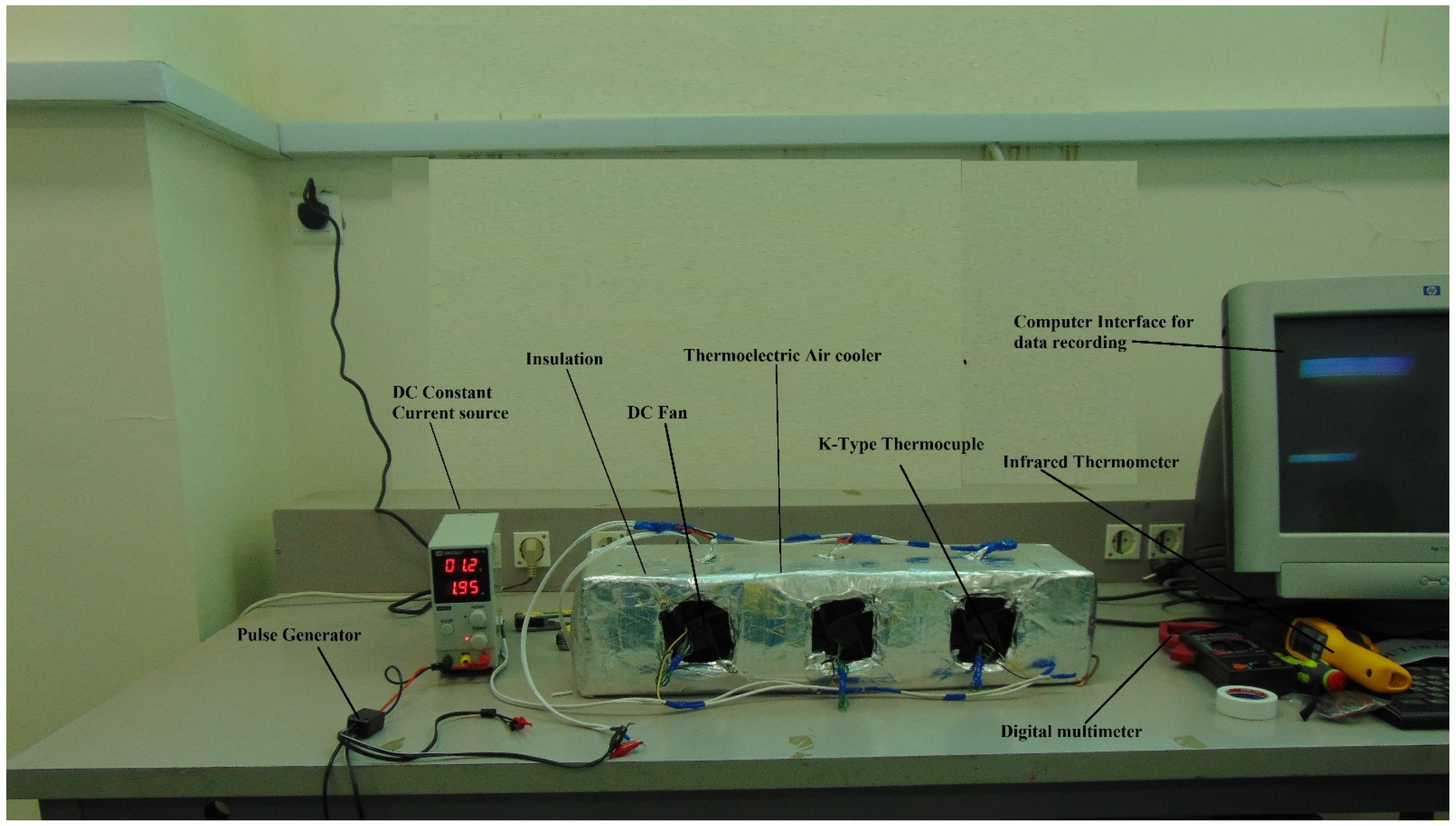
Using variable current pulses, the transient thermal characteristics of a thermoelectric air cooling system (TE-AC) were investigated. Three Ferrotec TEMs, model 9500/391/085b, are arranged inside an air duct, along with a heat sink and fans to dissipate the heat. Figure 1 depicts the experimental test setup, and Table 1 lists the TEM specifications. Under maximum operating conditions of 8.5 A current and 53.8 V voltage, the TEMs have a maximum cooling capacity of 248 W and a maximum temperature differential of 72 °C, as shown in Table 1. The experimental setup consist of constant DC supplier by Extech 382270. K-Type thermocouples were used to measure temperature, and data were continuously recorded in a data logger from a Graphtec GL840-20 channel and then transferred to a computer interface. The TEMs were installed inside an air duct that had been thermally insulated with aluminum foil to prevent heat transmission between the external environment and the air in the chamber. To increase the rate of heat dissipation, a heat sink and then a fan were also attached to both the cold and hot surfaces of TEMs. The time-varying electric current is measured using a digital multi-meter. The tests are carried out in a controlled environment with a temperature of 24 °C and a relative humidity of 60%.
Firstly, a steady test is performed to determine the input electric current that corresponds to the lowest cold side temperature, i.e., the optimal current. The input current to the TE-AC system was controlled by the DC current supply, which varied from 1 A to 7 A. It took over three hours to get the inlet and outlet temperatures of the heat sink connected to one of the TEMs to be nearly identical. The temperature recording trail was then stopped. Maintain constant monitoring of the heat sink’s intake and outlet temperatures for 10–20 min, then change the electric current input and start the next steady state experiment. By looking for the temperature data with the lowest recorded value, the optimal electric current can be found. During the transient trial, the first and second steps of the procedure are exactly the same as they are during the steady-state test. An electric current is then given to the TECs for 3 min at a constant rate, following which the current abruptly changes to a pulse current and then returns to the constant current after a specified time period has passed. In the current study, the pulse current is greater than the steady state current.
3. Results
The performance of both steady state and pulse operated thermoelectric air coolers is discussed in this section. The input operation current supply is increased from 1 A to 7 A in steady state operation, and the optimum performance is determined. The effect of different cooling loads on pulse width is evaluated in pulse operation, and the best configuration is determined.
3.1. Steady Continuous Operation of Thermoelectric Air Conditioner
The applied input currents to the TE-AC system range from 1 A to 7 A with a 1 A interval between each current applied. It was observed that the temperature of TEMs on the cold side initially decreases with time in the presence of a constant current applied to the TE-AC system before stabilizing at a stable value, as shown in Figure 2. Figure 2 also showed that the stable temperatures of the cold side of TEMs differed at different applied currents, implying that there is a critical current that allows the TEMs to reach the lowest possible temperature of the cold side. Moreover, it was found that the temperature of the cold side of the TEMs drops abruptly at the start of the experiment in all operational cases. This was because during the first phase of the experiment, the amount of Thomson and Joule heat generated inside TEMs was lower, and the Pettier cooling effect was stronger. The cold side temperature of TEMs increases with time when the input current is 4 A and 7 A, but decreases with time when the input operation current is 3 A, 5 A, and 6 A. This decrease in cold side temperature was not permanent because the Seebeck effect offset the applied current, resulting in increased Joule heating. The cold side temperature of TEMs increases after reaching its minimum value, as illustrated in Figure 2. After a period of time, the temperature of the cold side curve becomes monotonic in almost all operational situations. The temperature of the cold side of TEMs eventually reaches equilibrium regardless of the applied current due to the presence of equilibrium in Fourier heat, Peltier heat, and Joule heat, as shown in Figure 2. This implies that the stable cold-end temperatures at three currents, 3 A, 5 A, and 6 A, are lower than at the remaining two currents, 4 A and 7 A.
Figure 3 represent temperature variation cold side of TEMs with time when 10 W cooling load is applied at different operational currents. During the start of the experiment the temperature of cold side of the TEMs decreases for all operational cases. Because the Peltier effect prevails on the cold side of TEMs, all temperature curves fall. The temperature difference between the cold and hot sides grows larger as the experiment progresses. That is why, as shown in Figure 3, there was a significant increase in temperature on the cold side of the TEM. This occurs when the Seebeck effect takes precedence over the Peltier effect, resulting in an increase in cold side temperature. As the applied current to the TEMs increases from 3 A to 6 A, the Seebeck effect diminishes, resulting in a decrease in the cold side temperature of the TEMs. Further increase in input current, i.e., 7 A, results in a significant increase in cold side temperature. This occurs as a result of the Joule heating effect taking precedence over other phenomena. Because Joule heating is a volumetric effect as opposed to the Peltier effect, which is a surface effect, its effect appears later and lasts longer. During the initial stages of the experiment, the influence of the cooling load is the most significant. When comparing TEM with and without cooling load, the former case requires a higher input current to achieve the desired cold side temperature. As a result, TEMs have a higher initial surface temperature, as shown in Figure 3, than TEMs without a cooling load, as shown in Figure 2. The performance of TEMs is optimal when the input current is 6 A, as compared to other levels of input current, because both lower and higher current increase the cooling side temperature, lowering the sysTEM’s COP.
3.2. Pulse Operated Thermoelectric Air Conditioner
3.2.1. At Pulse Width of 40 s and Cooling Load 0 W to 20 W
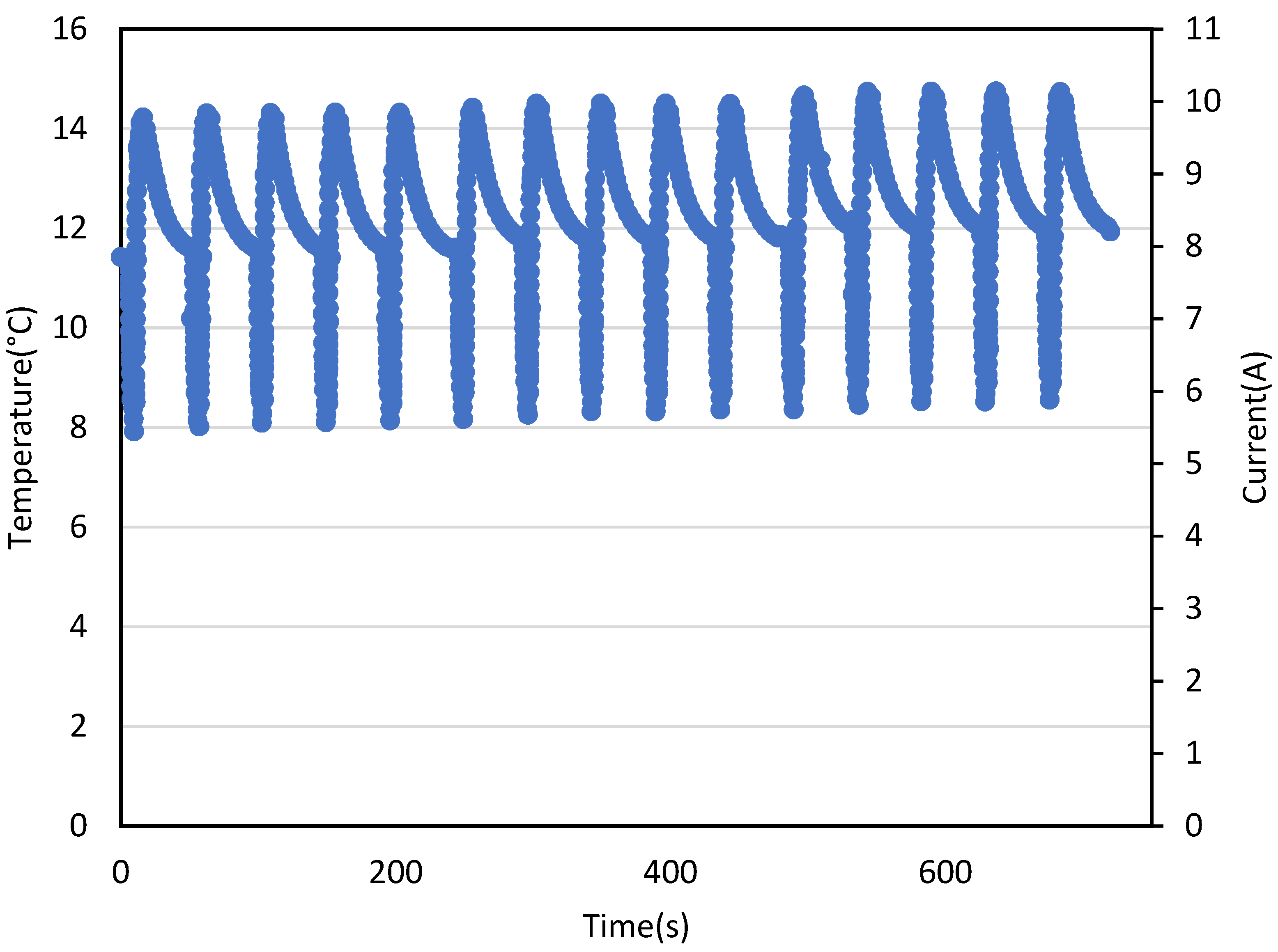
Figure 4, Figure 5 and Figure 6 show the fluctuation in temperature of cold side of TEMs operated under various cooling loads and constant current pulse widths of 40 s. For all of the cooling loads, the peak overshoot temperature of cold side of TEMs rises with time. As the experiment progresses, the hot side temperature of the TEMs rises due to accumulating Joule heat and Fourier heat conduction in the element of TEMs. These two factors causing peak overshoot in the TEMs. It is worthwhile to note that, as a result of the aforementioned cause, the lowest cold side temperatures are also rising. Initial minimum cold side temperature and overshoot peak temperature for TEMs operated at pulse width of 40s and cooling load of 0W were 3.75 °C and 9.89 °C, respectively, which increased with duration of experiment and reached to 4.21 °C and 10.76 °C, as shown in Figure 4. This could be because the Joule heat accumulated during each current pulse was not completely dissipated, resulting in a slight increase in the minimum temperature of TEMs.
In addition, as shown in Figure 4 and Figure 5, increasing the cooling load from 0 W to 10 W raises the initial minimum cold side temperature when compared to TEMs with no cooling load. For TEMs operating at a pulse width of 40 s and a cooling load of 10 W, the initial cold side temperature and overshoot peak temperature were 6.24 °C and 13.24 °C, respectively, which increased with the duration of the experiment and reached 7.32 °C and 13.81 °C, as shown in Figure 5.
Furthermore, as shown in Figure 6, increasing the cooling load from 10 W to 20 W increases the initial minimum cold side temperature more than TEMs with 10 W and no cooling load. For TEMs operating at a pulse width of 40 s and a cooling load of 10 W, the initial cold side temperature and overshoot peak temperature were 7.91 °C and 14.36 °C, respectively, which increased with the duration of the experiment and reached 8.51 °C and 14.92 °C, as shown in Figure 6.
3.2.2. At Pulse Width of 30 s and Cooling Load 0 W to 20 W
Figure 7, Figure 8 and Figure 9 show the fluctuation in temperature of cold side of TEMs operated under various cooling loads (i.e., 0 W, 10 W, and 20 W) and constant current pulse widths of 30 s. As the pulse width decreases from 40 s to 30 s the average cold side temperature increases. By comparing the initial minimum cold side temperature and overshoot peak temperature for TEMs operated at a pulse width of 40s, 30s, and a cooling load of 0 W, the temperatures were increased from 3.75 °C to 3.92 °C and 9.89 °C to 10.13 °C, respectively, as illustrated in Figure 4 and Figure 7. This increase in peak is greater than the current operation at pulse width of 40s. This implied that a decrease in pulse width resulted in more Joule heat accumulation during each current pulse that was not completely dissipated, resulting in a higher minimum temperature of TEMs.
The initial cold side and overshoot temperatures were increased from 6.24 °C to 7.17 °C and 13.24 °C to 13.69 °C, respectively, by increasing cooling load from no load condition to 10 W and current pulse width by 10 s, as shown in Figure 5 and Figure 8. As the experiment progresses, the overshoot temperature rises to 14.09 °C, as shown in Figure 8.
3.2.3. At Pulse Width of 9 s and Cooling Load 0 W to 20 W
Figure 10, Figure 11 and Figure 12 depict the temperature fluctuation of the cold side of TEMs operating under various cooling loads (such as 0 W, 10 W, and 20 W) and constant current pulse widths of 9 s. The average cold side temperature increases when the pulse width reduces from 40 to 9 s. Furthermore, as the experiment progressed to the middle phases, a jump in the minimum and overshoot temperature of the cold side of the TEMs was observed as shown in Figure 10, Figure 11 and Figure 12. This anomaly occurs due to a lack of current width, causing the hot side temperature of the TEMs to rise abruptly due to the accumulation of Joule heat in the element of the TEMs. Smaller pulse width resulted in more Joule heat accumulation during pulse operation, and lower thermal conductivity resulted in improper heat dissipation, lowering the TE-AC performance.
When no cooling load is applied, the initial minimum temperature and overshoot temperature of TEM were 4.75 °C and 10.28 °C, respectively, as illustrated in Figure 10. When the experiment is performed for 100 s, aberrant behavior occurs, and the minimum and overshoot temperatures rapidly climb to 10.32 °C and 17.43 °C, respectively, as shown in Figure 10.
The cooling performance of TEMs is degraded as the cooling load is increased from 0 W to 10 W and then to 20 W in successive steps. Such an effect is caused by increasing the load on TEMs in order to produce cooling within a specified time limit. As illustrated in Figure 11 and Figure 12, the 9 s current width is insufficient to enable adequate heat dissipation, and increasing cooling load causes additional Joule heating on the cold side of the TEMs. As a result, the minimum and overshoot temperature of cold side of TEMs’ rises. Furthermore, the thermal conductivity of TEMs has a significant impact on the performance of the TE-AC system during transient pulse operation. As shown in the graphs above, the cold side temperature of TEMs does not change significantly with thermal conductivity in the early stages of the experiment. Because Peltier cooling is the most critical component at first. The thermal conductivity increases as the experiment progresses, causing the cold side temperature to rise as more Joule heat is produced. Due to the reduced current width, the generated Joule heat did not have enough time to dissipate after each cycle and began to accumulate with the following pulses. Thus, decreasing the thermal conductivity of TEMs results in an increase in the ZT value and, consequently, in the COP of the TE-AC system.
4. Conclusions
In this study, performance of thermoelectric air conditioner system was investigated both under steady state current operation and pulse operated current operation. The following conclusions can be obtained from the study:
- The combined action of the Peltier heat, cooling load, Fourier heat, and Joule heat, all of which operate simultaneously during steady-state operation, determines the optimum performance of the cold side temperature of TEMs;
- During pulse operation, the peak overshoot and minimum temperature of the cold side of TEMs increased as the experiment progressed for all cooling loads;
- As the experiment progresses, two factors contribute to the increase in peak overshoot and minimum temperature of the cold side of TEMs. These factors include the accumulation of Joule heat in the element of TEMs and the increasing Fourier heat conduction in the element of TEMs;
- It was observed that the average cold side temperature increases as the pulse width was decreased from 40 s to 9 s;
- Lower current width causes an abrupt increase in the TEMs’ cold side minimum and overshoot temperatures. This anomaly occurs due to a lack of current width, which causes the hot side temperature of the TEMs to rise abruptly due to the accumulation of Joule heat in the TEMs’ element.
Finally, the pulse operation of a thermoelectric air conditioning system can provide better performance for building thermal management when compared to steady state operation. This research could be useful in the design of thermoelectric air conditioning systems for building space cooling applications that operate on pulses current.
Funding
This research was funded by the Deanship of Scientific Research (DSR) at King Fahd University of Petroleum & Minerals (KFUPM) through project number SR191010.
Institutional Review Board Statement
Not Applicable.
Informed Consent Statement
Not Applicable.
Data Availability Statement
The data presented in this study are available on request from the corresponding author.
Acknowledgments
The author would like to acknowledge the support provided by the Deanship of Scientific Research (DSR) at King Fahd University of Petroleum & Minerals (KFUPM) for funding this work through Project Number SR191010.
Conflicts of Interest
The authors declare no conflict of interest
References
- Lu, T.; Li, Y.; Zhang, J.; Ning, P.; Niu, P. Cooling and mechanical performance analysis of a trapezoidal thermoelectric cooler with variable cross-section. Energies 2020, 13, 6070. [Google Scholar] [CrossRef]
- Faddel, S.; Tian, G.; Zhou, Q. Decentralized management of commercial HVAC systems. Energies 2021, 14, 3024. [Google Scholar] [CrossRef]
- Lv, S.; Qian, Z.; Hu, D.; Li, X.; He, W. A comprehensive review of strategies and approaches for enhancing the performance of thermoelectric module. Energies 2020, 13, 3142. [Google Scholar] [CrossRef]
- Irshad, K.; Habib, K.; Saidur, R.; Kareem, M.W.; Saha, B.B. Study of thermoelectric and photovoltaic facade system for energy efficient building development: A review. J. Clean. Prod. 2019, 209, 1376–1395. [Google Scholar] [CrossRef]
- He, W.; Zhang, G.; Zhang, X.; Ji, J.; Li, G.; Zhao, X. Recent development and application of thermoelectric generator and cooler. Appl. Energy 2015, 143, 1–25. [Google Scholar] [CrossRef]
- Teffah, K.; Zhang, Y.; Mou, X.L. Modeling and experimentation of new thermoelectric cooler-thermoelectric generator module. Energies 2018, 11, 576. [Google Scholar] [CrossRef] [Green Version]
- Russel, M.K.; Ewing, D.; Ching, C.Y. Characterization of a thermoelectric cooler based thermal management system under different operating conditions. Appl. Therm. Eng. 2013. [Google Scholar] [CrossRef]
- Shittu, S.; Li, G.; Zhao, X.; Ma, X. Review of thermoelectric geometry and structure optimization for performance enhancement. Appl. Energy 2020. [Google Scholar] [CrossRef]
- Pourkiaei, S.M.; Ahmadi, M.H.; Sadeghzadeh, M.; Moosavi, S.; Pourfayaz, F.; Chen, L.; Yazdi, M.A.P.; Kumar, R. Thermoelectric cooler and thermoelectric generator devices: A review of present and potential applications, modeling and materials. Energy 2019. [Google Scholar] [CrossRef]
- Irshad, K.; Habib, K.; Kareem, M.W.; Basrawi, F.; Saha, B.B. Evaluation of thermal comfort in a test room equipped with a photovoltaic assisted thermo-electric air duct cooling system. Int. J. Hydrog. Energy 2017, 42, 26956–26972. [Google Scholar] [CrossRef] [Green Version]
- Cai, Y.; Wang, L.; Wang, W.W.; Liu, D.; Zhao, F.Y. Solar energy harvesting potential of a photovoltaic-thermoelectric cooling and power generation system: Bidirectional modeling and performance optimization. J. Clean. Prod. 2020. [Google Scholar] [CrossRef]
- Zhou, Y.; Zhang, T.; Wang, F.; Yu, Y. Numerical study and optimization of a combined thermoelectric assisted indirect evaporative cooling system. J. Therm. Sci. 2020. [Google Scholar] [CrossRef]
- Zheng, L.J.; Lim, S.; Kim, N.K.; Kang, D.H.; Youn, Y.J.; Lee, W.; Kang, H.W. Experimental study of a thin water-film evaporative cooling system to enhance the energy conversion efficiency of a thermoelectric device. Energy 2020. [Google Scholar] [CrossRef]
- Lamba, R.; Kaushik, S.C.; Tyagi, S.K. Geometric optimization of trapezoidal thermoelectric heat pump considering contact resistances through genetic algorithm. Int. J. Energy Res. 2018. [Google Scholar] [CrossRef]
- Liao, X.; Liu, Y.; Ren, J.; Guan, L.; Sang, X.; Wang, B.; Zhang, H.; Wang, Q.; Ma, T. Investigation of a double-PCM-based thermoelectric energy-harvesting device using temperature fluctuations in an ambient environment. Energy 2020. [Google Scholar] [CrossRef]
- Borhani, S.M.; Hosseini, M.J.; Pakrouh, R.; Ranjbar, A.A.; Nourian, A. Performance enhancement of a thermoelectric harvester with a PCM/Metal foam composite. Renew. Energy 2021. [Google Scholar] [CrossRef]
- Irshad, K.; Habib, K.; Algarni, S.; Saha, B.B.; Jamil, B. Sizing and life-cycle assessment of building integrated thermoelectric air cooling and photovoltaic wall system. Appl. Therm. Eng. 2019. [Google Scholar] [CrossRef]
- Ruiz-Ortega, P.E.; Olivares-Robles, M.A. Peltier supercooling in transient thermoelectrics: Spatial temperature profile and characteristic cooling length. Entropy 2019, 21, 226. [Google Scholar] [CrossRef] [PubMed] [Green Version]
- Mao, J.N.; Chen, H.X.; Jia, H.; Qian, X.L. The transient behavior of Peltier junctions pulsed with supercooling. J. Appl. Phys. 2012. [Google Scholar] [CrossRef]
- Wang, T.; Wu, H.; Gao, D.; Zhang, K.; Meng, J. Achieving better super-cooling in a two-stage transient thermoelectric device with constraint-free pulse current by multi-objective optimization. J. Therm. Sci. 2021. [Google Scholar] [CrossRef]
- Wang, S.L.; Liu, H.B.; Gao, Y.W.; Shen, Y.; Yang, Y.R.; Wang, X.D.; Lee, D.J. Transient supercooling performance of thermoelectric coolers with a continuous double current pulse. J. Taiwan Inst. Chem. Eng. 2021. [Google Scholar] [CrossRef]
- Gao, Y.W.; Shi, C.L.; Wang, X.D. Numerical analysis for transient supercooling effect of pulse current shapes on a two-stage thermoelectric cooler. Appl. Therm. Eng. 2019. [Google Scholar] [CrossRef]
- Chakraborty, A.; Ng, K.C. Thermodynamic formulation of temperature-entropy diagram for the transient operation of a pulsed thermoelectric cooler. Int. J. Heat Mass Transf. 2006. [Google Scholar] [CrossRef]
- Yang, R.; Chen, G.; Kumar, A.R.; Snyder, G.J.; Fleurial, J.P. Transient cooling of thermoelectric coolers and its applications for microdevices. Energy Convers. Manag. 2005. [Google Scholar] [CrossRef]
- Manno, M.; Wang, P.; Bar-Cohen, A. Pulsed thermoelectric cooling for improved suppression of a germanium hotspot. IEEE Trans. Compon. Packag. Manuf. Technol. 2014. [Google Scholar] [CrossRef]
- Snyder, G.J.; Fleurial, J.P.; Caillat, T.; Yang, R.; Chen, G. Supercooling of Peltier cooler using a current pulse. J. Appl. Phys. 2002. [Google Scholar] [CrossRef]
- Manikandan, S.; Kaushik, S.C.; Yang, R. Modified pulse operation of thermoelectric coolers for building cooling applications. Energy Convers. Manag. 2017, 140, 145–156. [Google Scholar] [CrossRef]
- Ma, M.; Yu, J.; Chen, J. An investigation on thermoelectric coolers operated with continuous current pulses. Energy Convers. Manag. 2015. [Google Scholar] [CrossRef]
- Piggott, A.J.; Allen, J.S. Peltier supercooling with isosceles current pulses: Cooling an object with internal heat generation. ECS J. Solid State Sci. Technol. 2017. [Google Scholar] [CrossRef]
- Shen, L.M.; Xiao, F.; Chen, H.X.; Wang, S.W. Numerical and experimental analysis of transient supercooling effect of voltage pulse on thermoelectric element. Int. J. Refrig. 2012. [Google Scholar] [CrossRef]
- Ma, M.; Yu, J. Experimental study on transient cooling characteristics of a realistic thermoelectric module under a current pulse operation. Energy Convers. Manag. 2016. [Google Scholar] [CrossRef]
- Lv, H.; Wang, X.D.; Meng, J.H.; Wang, T.H.; Yan, W.M. Enhancement of maximum temperature drop across thermoelectric cooler through two-stage design and transient supercooling effect. Appl. Energy 2016. [Google Scholar] [CrossRef]
- Gao, Y.W.; Lv, H.; Wang, X.D.; Yan, W.M. Enhanced Peltier cooling of two-stage thermoelectric cooler via pulse currents. Int. J. Heat Mass Transf. 2017. [Google Scholar] [CrossRef]
- Ruiz-Ortega, P.E.; Olivares-Robles, M.A.; Badillo-Ruiz, C.A. Transient thermal behavior of a segmented thermoelectric cooler with variable cross-sectional areas. Int. J. Energy Res. 2021. [Google Scholar] [CrossRef]
- Yin, T.; He, Z.Z. Analytical model-based optimization of the thermoelectric cooler with temperature-dependent materials under different operating conditions. Appl. Energy 2021. [Google Scholar] [CrossRef]
- Li, W.K.; Chang, J.H.; Amani, M.; Yang, T.F.; Yan, W.M. Experimental study on transient supercooling of two-stage thermoelectric cooler. Case Stud. Therm. Eng. 2019. [Google Scholar] [CrossRef]
Figure 1.
Experimental setup.

Figure 2.
Steady state operation of thermoelectric air cooler at 0 W cooling load.

Figure 3.
Steady state operation of thermoelectric air cooler at 10 W cooling load.

Figure 4.
Variation of TEM cold side temperature with time and current with a current pulse of 40 s and a cooling load of 0 W.
Figure 4.
Variation of TEM cold side temperature with time and current with a current pulse of 40 s and a cooling load of 0 W.

Figure 5.
Variation of TEM cold side temperature with time and current with a current pulse of 40 s and a cooling load of 10 W.
Figure 5.
Variation of TEM cold side temperature with time and current with a current pulse of 40 s and a cooling load of 10 W.

Figure 6.
Variation of TEM cold side temperature with time and current with a current pulse of 40 s and a cooling load of 20 W.
Figure 6.
Variation of TEM cold side temperature with time and current with a current pulse of 40 s and a cooling load of 20 W.

Figure 7.
Variation of TEM cold side temperature with time and current at 30 s current pulse and 0 W cooling load.
Figure 7.
Variation of TEM cold side temperature with time and current at 30 s current pulse and 0 W cooling load.

Figure 8.
Temperature variation of TEMs’ cold sides with time and current at 30 s current pulse and 10 W cooling load.
Figure 8.
Temperature variation of TEMs’ cold sides with time and current at 30 s current pulse and 10 W cooling load.

Figure 9.
Variation of TEM cold side temperature with time and current at 30 s current pulse and 20 W cooling load.
Figure 9.
Variation of TEM cold side temperature with time and current at 30 s current pulse and 20 W cooling load.

Figure 10.
Variation of TEM cold side temperature with time and current at 9 s current pulse and 0 W cooling load.
Figure 10.
Variation of TEM cold side temperature with time and current at 9 s current pulse and 0 W cooling load.

Figure 11.
Cold side temperature of TEMs varies with time and current at 9 s current pulse and 10 W cooling load.
Figure 11.
Cold side temperature of TEMs varies with time and current at 9 s current pulse and 10 W cooling load.

Figure 12.
Variation of TEM cold side temperature with time and current at 9 s current pulse and 20 W cooling load.
Figure 12.
Variation of TEM cold side temperature with time and current at 9 s current pulse and 20 W cooling load.


Table 1.
Specification of thermoelectric module.
| Specifications | Values | Units |
|---|---|---|
| Ferrortech 9500/391/085b | ||
| 53.8 | V | |
| 248 | W | |
| 8.5 | A | |
| 72 | °C | |
| 2.882 × 10⁻³ | K-1 | |
| ZT (50 °C on the hot side of TEM) | 0.93 | - |
Publisher’s Note: MDPI stays neutral with regard to jurisdictional claims in published maps and institutional affiliations. |
© 2021 by the author. Licensee MDPI, Basel, Switzerland. This article is an open access article distributed under the terms and conditions of the Creative Commons Attribution (CC BY) license (https://creativecommons.org/licenses/by/4.0/).
Share and Cite
MDPI and ACS Style
Irshad, K. Performance Improvement of Thermoelectric Air Cooler System by Using Variable-Pulse Current for Building Applications. Sustainability 2021, 13, 9682. https://0-doi-org.brum.beds.ac.uk/10.3390/su13179682
AMA Style
Irshad K. Performance Improvement of Thermoelectric Air Cooler System by Using Variable-Pulse Current for Building Applications. Sustainability. 2021; 13(17):9682. https://0-doi-org.brum.beds.ac.uk/10.3390/su13179682
Chicago/Turabian StyleIrshad, Kashif. 2021. "Performance Improvement of Thermoelectric Air Cooler System by Using Variable-Pulse Current for Building Applications" Sustainability 13, no. 17: 9682. https://0-doi-org.brum.beds.ac.uk/10.3390/su13179682
Note that from the first issue of 2016, this journal uses article numbers instead of page numbers. See further details here.