Article

High-Efficiency Combined Heat and Power through a High-Temperature Polymer Electrolyte Membrane Fuel Cell and Gas Turbine Hybrid System

Department of Economics, Engineering, Society and Business Organization, University of Tuscia, 01100 Viterbo, Italy
*
Author to whom correspondence should be addressed.
Sustainability 2021, 13(22), 12515; https://0-doi-org.brum.beds.ac.uk/10.3390/su132212515
Submission received: 4 October 2021 / Revised: 5 November 2021 / Accepted: 9 November 2021 / Published: 12 November 2021

Abstract

:
High-temperature proton-exchange membrane fuel cells are a promising technology for distributed power generation thanks to their high-power density, high efficiency, low emissions, fast start-up, and excellent dynamic characteristics, together with their high tolerance to CO poisoning (i.e., CO in the feed up to 3%). In this paper, we present an innovative, simple, and efficient hybrid high-temperature proton-exchange membrane fuel cell gas turbine combined heat and power system whose fuel processor relies on partial oxidation. Moreover, we demonstrate that the state-of-the-art fuel processors based on steam reformation may not be the optimal choice for high-temperature proton-exchange membrane fuel cells’ power plants. Through steady-state modeling, we determine the optimal operating conditions and the performance of the proposed innovative power plant. The results show that the proposed hybrid combined heat and power system achieves an electrical efficiency close to 50 % and total efficiency of over 85 % , while a state-of-the-art system based on steam reformation has an electrical efficiency lower than 45 % . The proposed innovative plant consists of a regenerative scheme with a limited power ratio between the turbine and fuel cell and limited optimal compression ratio. Therefore, micro-gas turbines are the most fitting type of turbomachinery for the hybrid system.

1. Introduction

The development of high-efficiency distributed energy conversion systems is a major achievement towards the reduction in anthropic emissions of greenhouse gases and the increase in energy accessibility [1,2]. According to the Intergovernmental Panel on Climate Change [3], if the CO 2 concentration remains below 450 ppm, the average global temperature rise should remain below 2 ° C. Notably, a global temperature increase of over 2 ° C could significantly affect human life through sea level rises and more frequent extreme weather events [4]. In 2019, the atmospheric CO 2 concentration was to 410 ppm [5], while it was never higher than 300 ppm before the 20th century (in the past 420,000 years), clearly indicating the impact of recent human activities [6]. Energy generation is one of the major sources of CO 2 emissions, accounting, together with cement, for more than 35 billion tons in 2019 [7]. In the US, the percentage of CO 2 for electricity generation and energy-related uses is 61% of the total emissions [8], while in the European union, the share of CO 2 emitted by energy generation ranges from 10% to 70% [9].
Combined Heat and Power (CHP) systems dominate Distributed Generation (DG), ensuring a reliable energy conversion with relevant economic savings [10,11,12,13,14,15,16,17], while offering several other opportunities, such as: (i) Higher total efficiency compared to separate production [2,18]; (ii) Reduced pollutants and green-house gas emissions [1,2]; (iii) Reduced investments in large-capacity power plants [2], and transmission and distribution lines [1]; (iv) Reduced distribution losses [1]; (v) Grid-support and ancillary service [1], and (vi) local integration with Renewable Energy Sources (RES) [2,19,20,21,22,23,24]. Fuel Cells (FCs) particularly fit the application in distributed CHP plants [16,25,26,27,28,29] due to their high efficiency in a broad range of nominal power [30], favorable part-load characteristics [18,31,32,33], low pollutant emissions [34], and operation without noise and vibrations [35]. The positive technical characteristics of FCs result in a continuously developing market [36,37,38,39]. In 2020, the newly shipped FC systems accounted for 82,400 units, corresponding to more than 1.3GW of the nominal power, considering transportation, stationary, and portable systems. The figures were 72,500 units in 2019 for 1.2 GW, and 68,500 units for 0.8GW in 2018. In this context, the stationary systems alone accounted for 57,800 shipped units over the total 82,400 units (i.e., more than 70%) meaning that stationary power generation is one of the most relevant applications for FCs.
Proton Exchange Membrane Fuel Cells (PEMFCs) are the most commercially successful type, with more than 1GW of the nominal power of new shipped systems in 2020 (78% of the total) [39]. This commercial success compared to other types of FCs is due to their reliability, high-power density, fast start-up, and excellent dynamic characteristics [31,32,33]. However, the state-of-the-art Low Temperature-Proton Exchange Membrane Fuel Cells (LT-PEMFCs), that operate between 60 ° C and 90 ° C [40], need high-purity hydrogen (i.e., CO concentration lower than 10 ppm) and show large polarization losses at high current densities for limited oxygen mass transport [41]. When hydrogen is produced from hydrocarbons, the purification can significantly affect the overal CHP system efficiency [42,43], even considering efficient alternatives to state-of-the-art Pressure Swing Adsorption (PSA) systems, such as selective mebranes [43,44,45,46,47,48,49,50,51]. High-Temperature Proton-Exchange Membrane Fuel Cells (HT-PEMFCs) operate between 120 ° C and 250 ° C with several advantages compared to LT-PEMFCs, such as [41]: (i) improved reaction kinetics that can lead to lower Pt loading or even Pt-free designs; (ii) increased fuel impurity tolerance (CO up to 3% [25,41,52,53,54,55,56]); (iii) simplified plate design; (iv) easier thermal and water management; (v) easier integration in CHP systems. As a consequence, HT-PEMFCs are competitive on the market. Table 1 shows that several companies are commercially developing HT-PEMFCs components as well as complete systems for transportation (passenger cars, light and heavy-duty vehicles), stationary power generation (CHP systems, back-up power, and off-grid), portable power generation, maritime, and aviation (aircrafts, electric vertical takeoff and landing flying cars, and drones) applications.
However, HT-PEMFCs still need some improvements, such as [41] limiting the degradation of the catalysts and the proton exchange membrane, avoiding corrosion and mechanical failure of bipolar plates, and improving the design of the the system, so that it has better thermal integration. The research into catalysts has focused on improving platinum group material-based components by studying innovative alloys [62,63], improving carbon support with carbon doping [64,65,66,67] and polymer wrapping [68], and modifying the catalyst layer structure [69]. Moreover, alternative catalyst platinum-group materials have been studied, obtaining promising results [70,71,72,73,74]. Phosphoric Acid (PA)-doped polybenzimidazole (PBI) membranes represent the state-of-the-art material for HT-PEMFCs membranes, given their high conductivity and excellent thermal stability, and the low PA vapor pressure at high temperatures. The research on such membranes resulted in the development of PA-doped BI composite mebranes [75,76,77,78,79] with higher mechanical and thermal stability, along with improved conductivity. Moreover, innovative acid base membranes that implement non-aqueous solvents and alternative polymers have been developed [80,81,82,83]. Several bipolar plate materials such as graphite [84,85], and different types of stainless steel [86,87], have been investigated. Moreover, several techniques, such as coatings [88,89,90,91] and innovative manufacturing processes, have been studied to improve the performance of such components [86,92,93].
Modeling and experimental analyses of complete systems based on HT-PEMFCs are pivotal when evaluating the impact of the above-mentioned research on innovative materials and technological development. System-level studies found in the literature mostly focuses on a single cell or stack, which often do not consider fundamental aspects such as fuel-processing to produce hydrogen from hydrocarbons [41]. Only a few studies have explored the steady-state performance of an HT-PEMFCs CHP, including a steam reformation-based fuel processors with simplified or absent purification, considering Natural Gas (NG) [16,25,56], methanol [94], and glycerol [95] feeds. Other studies focus on the dynamic performance [96,97], control and operation [98,99], and long-term performance and degradation [55,100,101] of such systems. Steam reformation is the most efficient reaction when considering only the hydrogen yield of the reactor. However, when considering the whole fuel processor, the thermal power necessary to sustain such a reaction should also be taken into account. In this scenario, the exothermic Partial Oxidation (POX) is potentially more efficient [102], with a better dynamic performance than an endothermic steam-reformation reactor. The usage of POX-based fuel processors for HT-PEMFC’s stationary systems is almost untapped in the literature, with only a few applications for mobility and aviation systems [103].
The POX reactor has an optimal operation at 1000 ° C [32,102], producing syngas with a higher temperature and enthalpy than the requirements of HT-PEMFC (i.e., at a temperature between 160 ° C and 200 ° C). By increasing the operating pressure of the POX, this enthalpy difference can be converted into electrical power through a Gas Turbine (GT). Although the yield of the POX reaction decreases at high pressures, the overall CHP efficiency can increase, thanks to the additional electric power from the GT. Moreover, the fuel processor would not rely on FC power to run the auxiliary systems; therefore, the overall system would have a better dynamic. Notably, state-of-the-art turbines materials tolerate temperatures up to 1000 ° C without the need for special coatings or blade cooling. Therefore, the syngas produced athrough POX reaction can expand in GTs of any size, ranging from a few kW to multi-MW nominal power [104,105].
Several FC-GT hybrid systems have been studied, but only focusing on high-temperature fuel cells such as Solid Oxide Fuel Cells (SOFCs) [106,107] and Molten Carbonate Fuel Cells (MCFCs) [108,109,110,111,112]. Several working prototypes of such systems have been studied from Siemens-Westinghouse [113], Rolls-Royce Fuel Cell Systems [114], and Mitsubishi Hitachi Power Systems [115], etc. [106]. The most advanced and substantial of sthese prototypes is the Mitsubishi Hitachi Power Systems, which reached commercial readiness with the 250kW MEGAMIE system developed in collaboration with Toyota as supplier of the micro-turbine [39,116,117]. However, we note that none of the cited papers integrates the turbine in the fuel processor of an FC-based CHP plant. Only a few works consider hybrid systems with HT-PEMFCs, but these only concern the conversion of thermal power through organic Rankine cycles [118].
In this paper, we study the performance of a hybrid HT-PEMFC-GT CHP system whose fuel processor runs on the POX reaction to produce hydrogen. Specifically, we build a 0-D model for the fuel processor and a 1-D model for the HT-PEMFC to characterize the performance of the proposed innovative system while evaluating the optimal operating parameters. Moreover, we compare the results to those obtained with state-of-the-art systems, with HT-PEMFC CHP system implementing a steam-reformation-based fuel processor. The paper is organized as follows. Section 2 introduces the innovative analyzed CHP system. Section 3 describes the modeling methodology, while Section 4 and Section 5 present and discuss the results. Finally, Section 6 draws the conclusions of the work.

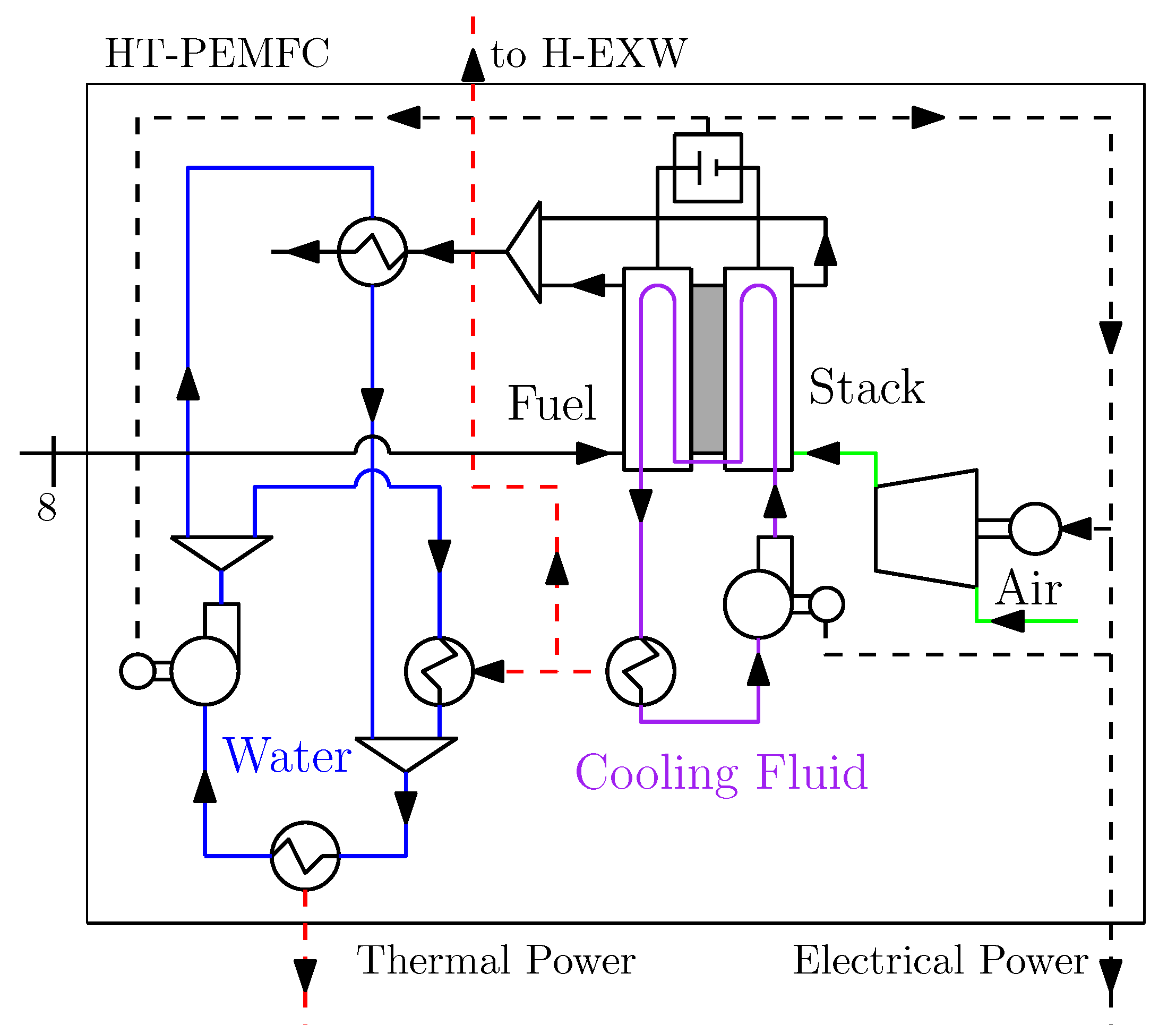
2. System Description

In this paper, we preliminarily design and dissect the performance of a hybrid CHP system, integrating a HT-PEMFC and a micro-Gas Turbine (Figure 1). Specifically, we consider: (i) a gas turbine made of state-of-the-art materials that can withstand 1000 ° C inlet temperature without blade cooling, and (ii) a state-of-the-art HT-PEMFC stack based on phosphoric-acid-doped PBI membranes. The FC operates in a temperature range from 160 ° C to 200 ° C, and at a pressure between 1 bar and 2 bar [103]. The tolerance to impurities in the feeding fuel can be increased by increasing both operating temperature and pressure [103]. However, one of the main degradation mechanisms for HT-PEMFC is phosphoric acid evaporation, which exponentially increases as a function of the operating temperature [103,119]. Therefore, we selected an operating temperature T FC = 180 ° C as a trade-off between expected durability and impurity tolerance. Moreover, the FC operates at atmospheric pressure to avoid back-pressure downstream the gas turbine.
The fuel-processing section of the proposed CHP system derives from a regenerative gas turbine scheme with the addition of a Low-Temperature Water Gas Shift Reactor (LT-WGSR). Referring to Figure 1, the compressors NG-C and AIR-C increase the pressure of NG and air, respectively, according to the imposed pressure ratio (see Section 3.4). Herein, we conservatively consider the NG as being available at 1bar, as for small applications. However, we note that, for larger systems, the NG is usually available at a much higher pressure and the NG compressor is unnecessary. The compressed mix of NG and air (state 1) goes through the heat exchanger H-EX, increasing its temperature (state 2) by subtracting thermal power from the syngas expanded in the GT. The amount of thermal power exchanged in H-EX is determined to keep the oxidizer outlet temperature (state 3) at 1000 ° C, assuming that the oxidizer is an adiabatic reactor. This temperature is thermodynamically optimal for the POX reaction, as evidenced from the peak value of the fuel conversion and of the CO and H 2 reflectivities [102]. The main reaction occurring in the oxidizer is partial oxidation:
C y H z + y 2 O 2 y CO + z 2 H 2 ,
which is exothermic ( Δ h POX = 35.7 kJ / mol for methane) and takes place at 1000 ° C [32,102]. Moreover, the produced carbon monoxide can react with water to produce hydrogen according to the Water Gas Shift (WGS) reaction:
CO + H 2 O H 2 + CO 2 .
Depending on the ratio of oxygen to natural gas flow rate, complete oxidation can also occur:
C y H z + z 4 + y O 2 z 2 H 2 O + y CO 2 ,
which is exothermic ( Δ h SW = 890 kJ / mol for methane) and does not produce hydrogen. After the Oxidator (state 3), the syngas expands in the GT (state 4), and then goes through the H-EX (state 5). The cooled syngas mixes with water before entering the WGSR (state 7). The water is pre-heated (state 6) with thermal power from the FC cooling system to keep the mixture temperature just above the dew point. This gas mixture proceeds through the WGSR, a cooled reactor that operates at the FC temperature (180 ° C). Thus, the WGSR also works as a pre-heater for the FC stack, simplifying its thermal management. The WGSR temperature complies with the operating range of state-of-the-art copper-based catalysts for low-temperature WGS [120,121].
Figure 1 represents a simplified conceptual system that might be modified for a detailed design, without affecting the presented conclusions. The simplifications mainly regard the mixing of air and NG, and the single driveshaft configuration for turbine and compressors. In state-of-the-art gas turbine systems, that work with a high level of air excess, NG is injected directly in the combustion chamber. However, in the proposed scheme, the NG and the air mass flow rates are comparable. Therefore, pre-heating the NG with air has a relevant impact on the performance of the overall system. For this reason, we mix air and NG before H-EX. We note that this mixture is rich (NG molar fraction > 23 % ) and should not generate unwanted spontaneous reactions in the H-EX. In any case (e.g., safety requirements), the pre-heating of air and NG could also take place in an ad-hoc-designed heat exchanger that keeps the reactants separated (i.e., concentric tubes). The single driveshaft configuration may not be practically realizable because the volumetric flow rates processed in the two compressors and the turbine are different. However, with an ad-hoc design (e.g., electrical power transmission or specific turbomachinery selection), a system that achieves the presented thermodynamic results can be realized.
Figure 2 represents a schematic overview of the HT-PEMFC stack with a balance of plant components. External air enters the cathode after being compressed to overcome FC pressure drops. Syngas from the fuel processor (state 8) enters the anode. The hot flue gases (180 ° C) are used for cogeneration. The thermal power extracted from the FC through the cooling fluid is used to pre-heat water in H-EXW and for cogeneration. We assume that the return temperature of cogenerative water is 70 ° C, and that it is incremented to 80 ° C. We define W FC as the net fuel cell electrical power. To obtain W FC , we subtract the power to run the compressor of the air feeding the fuel cell cathode, and the pumps to circulate the coolant fluids from the gross fuel cell power output.

3. Methodology

3.1. Fuel Processor Modeling

We study the performance of the proposed energy system through a steady-state lumped parameter approach in Aspen Plus [122] environment. We use the Peng Robinson equation [122] of state and the steamNBS tables [123] to compute the thermodynamic properties of the working fluids. The main submodels are: (i) oxidation reactor, (ii) water gas shift reactor, (iii) heat exchangers, and (iv) turbine, compressors and pumps.
The oxidizer and the water gas shift reactors are modeled as equilibrium reactors (called RGibbs in the modeling environment), calculating the equilibrium composition of the reaction products by minimizing the Gibbs free energy [122]. We assume that the POX reactor is adiabatic. Therefore, the produced thermal power increases the syngas temperature. The WGS is a constant temperature reactor, where the produced thermal power is both absorbed by the reactants to reach the operating temperature and available for cogeneration purposes.
We model the H-EX and the cogenerative heat exchangers in the FC plant through the logarithmic mean temperature difference approach. Conversely, only the cold side of the H-EXW is modelled because the thermal power is directly supplied by the FC stack and temperature crossover between water and the heat transfer fluid is not possible. In fact, the water at the outlet of H-EXW is changing phase at 104 ° C (i.e., 1.08bar pressure) with a steam quality between 0.2 and 0.55, whereas the FC stack thermal power is available at a constant temperature of 180 ° C (or, more practically, 160 ° C considering 10 ° C temperature difference for both the heat exchange in the FC and in H-EXW), and is almost 10 times larger than required. Since we do not perform any off-design analysis, we implicitly vary the heat exchangers size for every case, and consider the heat transfer coefficient constant.
Equation (4) defines the electrical power produced by the turbine:
W T = η m , T h 3 h 4 ,
where η m , T = 0.9 is the mechanical efficiency of the turbine, while h 3 and h 4 are the input and output enthalpy of the fluid, calculated according to the Peng–Robinson equation of state [122] and assuming the polytropic efficiency of the turbine η p , T = 0.825 . Similarly, the electrical power consumed by pumps and compressors is:
W C = h out h in η m , C ,
where η m , C = 0.9 is the mechanical efficiency of the compressor or pump and the enthalpy values are calculated assuming the polytropic efficiency η p , C = 0.85 . The values assumed for polytropic and mechanical efficiency are conservative, so that they are appropriate for small-scale systems as well [104,105].
We also consider the following relative pressure drops [52,104,105]: 1% in the inlet, 3% in both the cold and hot sides of H-EX, 3% in the oxidizer, 3% in WGSR, and finally 5% in the FC stack.

3.2. Fuel Cell Modeling

We study the performance of the HT-PEMFC stack through a 1D flux-based mathematical model [32,124,125,126,127,128,129,130], where the molar fraction of reactants and products vary according to the thickness of the anode and the cathode. Moreover, the temperature is homogeneous and the convective and diffusive transport phenomena are negligible. The catalyst layers are thin enough to act as interfaces [131]. At an operating temperature of 180 ° C, water exists only in the vapor-phase. The membrane only conducts protons and is impervious to gases and liquids. As a consequence, the back-diffusion of water is negligible [54,132,133]. Finally, the voltage loss due to carbon monoxide is discarded because the CO molar fraction in the anode feed is always lower than 1% (specifically, between 0.2% and 0.4% depending on the operating condition, as reported in Section 3.4 and Section 4) [53,95,134,135].
Equation (6) defines the fuel cell operating voltage
V = E η Ω η act η conc ,
where η Ω , η act , and η conc are the ohmic, activation, and concentration overpotentials, respectively. E is the thermodinamically predicted reversible FC voltage:
E = Δ g ^ n H 2 F ,
where Δ g ^ is the Gibbs free energy variation for hydrogen oxidation H 2 + 1 2 O 2 H 2 O at the inlet reactants operating conditions, n H 2 = 2 is the number of electrons involved in the reaction, and F = 96,485 C / mol is the Faraday’s constant.
Ohmic losses occur in the membrane and electrode and linearly vary with the current density j[2j]jFC current density:
η Ω = j t m σ m + t a + t c σ el + r conc ,
where r conc is an additional resistance used as a fitting parameter for variable inlet hydrogen concentration, t m , t a , and t c are the thickness of the membrane, the anode, and the cathode, respectively; σ m is the membrane proton conductivity, and σ el is the electron conductivity of the electrodes.
The proton conductivity of the PA-doped PBI membrane can be expressed in S / m with the following semi-empirical correlation based on Arrhenius Law and experimental data [134,135]
σ m = A B T FC exp E a T FC ,
where A and B are pre-exponential factors, and E a is the activation energy, expressed in J / kmol , T FC [ K ] is the FC temperature, and = 8314 J / ( kmol K ) is the universal gas constant. The activation energy varies as a function of the phosphoric acid doping level of PBI membranes:
E a = 619.6 Θ + 21 , 750 ,
where Θ is the doping level and is defined as the number of phosphoric acid molecules per PBI repeat unit. The pre-exponential factor A also considers the effect of the doping level:
A = 168 Θ 3 6324 Θ 2 + 65 , 760 Θ + 8460 .
The pre-exponential factor B if a function of the average relative humidity ( ξ ) between anode and cathode) and of T FC :
B = 1 + 0.01704 T FC 4.767 ξ if 373 K T FC 413 K 1 + 0.1432 T FC 56.89 ξ if 413 K < T FC 453 K 1 + 0.7 T FC 309.2 ξ if 453 K < T FC 473 K .
The mathematical formulation for η act derives from the Butler–Volmer equation for ideal gases in the simplified form for high-current densities (i.e., it only considers the reactants concentration):
η act = η act , c + η act , a = T FC n O 2 α c F ln j j 0 , c p c x O 2 , c + T FC n H 2 α a F ln j j 0 , a p a x H 2 , a ,
where n O 2 = 4 is the number of electrons moles consumed per O 2 mole. In Equation (13), the subscripts c and a refer to cathode and anode, respectively, α is the transfer coefficient, j 0 is the exchange current density, p is the operating pressure, x O 2 and x H 2 are the oxygen and hydrogen molar fractions in the reacting gas mixtures. Specifically, x O 2 and x H 2 are computed through the following equations, derived from the Fick’s law of binary diffusion:
x O 2 , c = x O 2 , cIN t c j T FC n O 2 F p c D O 2 H 2 O eff Δ D ,
x H 2 , a = x H 2 , aIN t a j T FC n H 2 F p a D H 2 CO 2 eff Δ D ,
where x O 2 , cIN is the oxygen molar fraction at the cathode feed, and x H 2 , aIN is the hydrogen molar fraction at the anode feed, D O 2 H 2 O eff is the effective diffusivity of oxygen in water, and D H 2 CO 2 eff is the effective diffusivity of hydrogen in carbon dioxide, Δ D is a correction factor used to update the model for variable inlet hydrogen concentrations. The general relation for the effective binary diffusivity of species i through species j reads [136]:
D i j eff = ζ p T FC T c i T c j θ p c i p c j 1 / 3 T c i T c j 5 / 12 1 M i + 1 M j 1 / 2 ε τ ,
where T c is the critical temperature, p c is the critical pressure, M is the molecular weight, and ε and τ are the porosity and the tortuosity of the media through which diffusion occurs. For non-polar gases, ζ = 2.745 × 10 4 and θ = 1.823 , while ζ = 3.64 × 10 4 and θ = 2.334 for couples including polar gases [136]. We only consider binary diffusion because N 2 is a neutral gas and the molar fraction of components other than O 2 , H 2 O, H 2 , and CO 2 is lower than 1%.
The concentration overpotential is modeled through the Nernst equation:
η conc = η conc , c + η conc , a = T FC n O 2 F ln j L , c j L , c j + T FC n H 2 F ln j L , a j L , a j ,
where j L , c and j L , a are the cathodic and anodic current densities at which the reactants concentrations in the catalyst layer is zero. They are determined through Equations (18) and (19):
j L , c = n O 2 F D O 2 H 2 O eff Δ D c O 2 , cIN t c ,
j L , a = n H 2 F D H 2 CO 2 eff Δ D c H 2 , aIN t a ,
where c O 2 , cIN and c H 2 , aIN are the concentration of oxygen at the cathode feed, and of hydrogen at the anode feed.

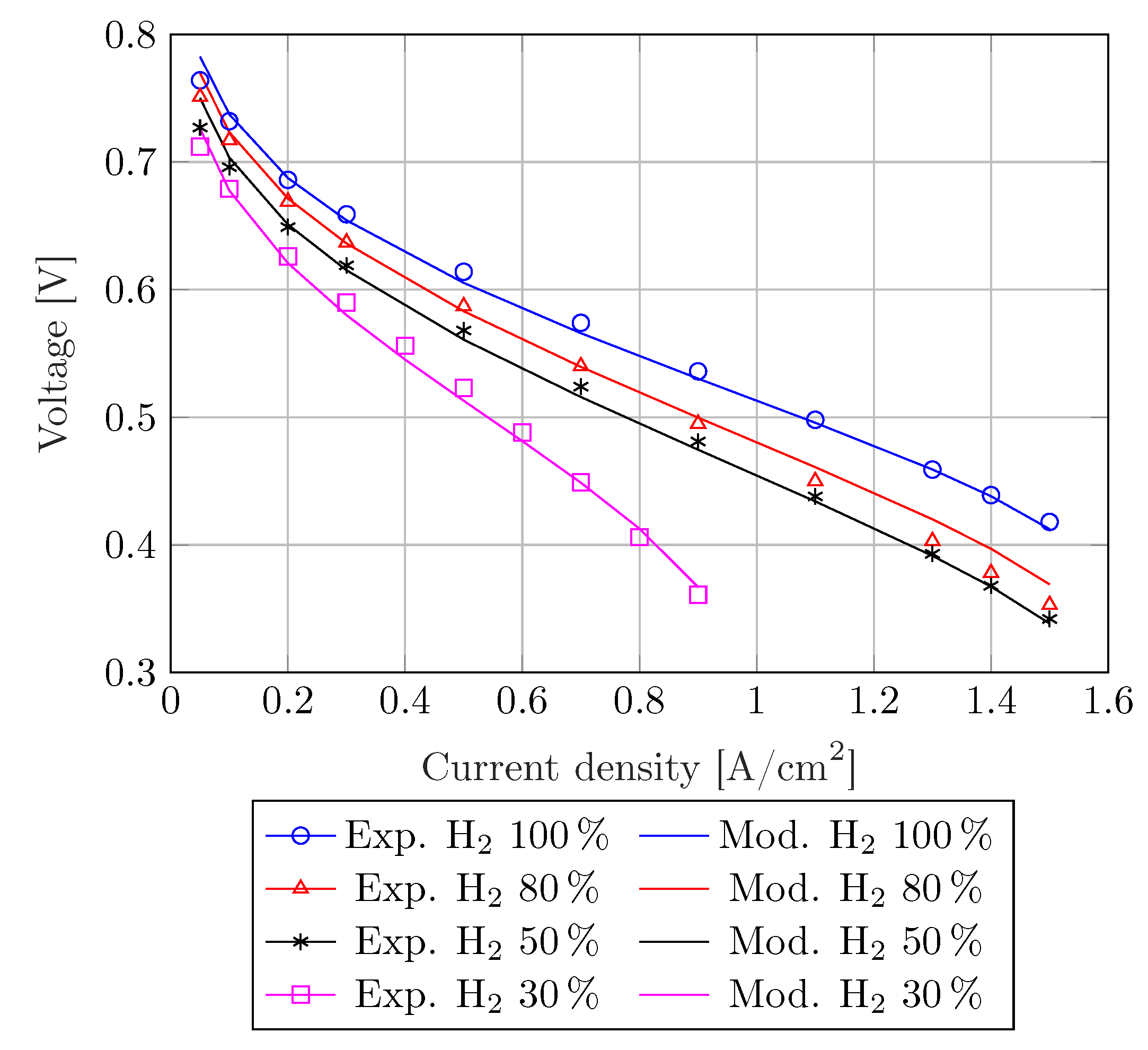
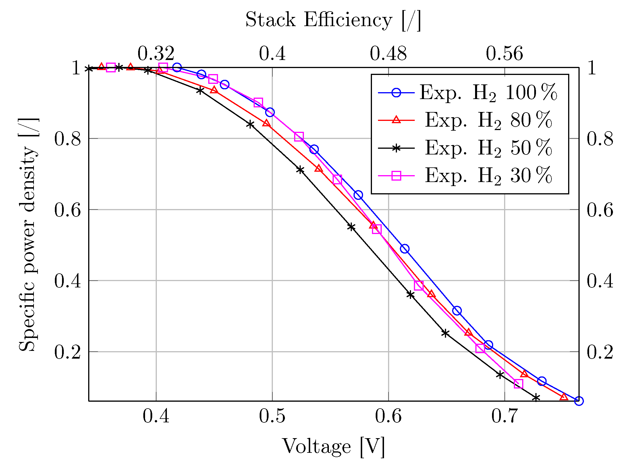
Fuel Cell Model Validation

The proposed FC model is validated against experimental data from [52] for a PA-doped, PBI-based HT-PEM (BASF Celtec) operating at 180 ° C and 1bar, and with an anodic hydrogen fraction ranging from 30 % to 100%. Table 2 and Table 3 report the model inputs, including the Utilization Factor (UF) of oxygen and of hydrogen [52,54]. The values of r conc , j 0 , a , and Δ D are linearly interpolated for intermediate hydrogen fractions. The anodic exchange current density j 0 , a monotonically decreases as the H 2 fraction in the feeding fuel decreases, as expected from j 0 , a definition. Conversely, the additional resistance r conc has a threshold behavior, switching from pure hydrogen to syngas mixture operation. Finally, we note that Δ D is only relevant for very low H 2 fractions (i.e., ≤ 30 % ). To quantify the agreement between experiments and model, we use the overall mean absolute percentage error [137,138]:
MAPE = 1 n k = 1 n 100 × V m ( k ) V e ( k ) V m ( k ) ,
where n is the number of samples, V m is the model predicted voltage, and V e is the experimental value. Experimental and modeled polarization curves, reported in Figure 3, show a good qualitative agreement. Quantitatively, MAPE = 1.31 % , assuming the parameters of Table 3.
For the studied CHP power plant, the H 2 fraction in the feeding syngas ranges from 42% to 62%, depending on the fuel-processor operating conditions (see Section 3.4 and Section 4), and is within the experimental data range ([30–100%]). Therefore, the validated model is suitable for predicting the performance of the analyzed system. Since we never consider pure hydrogen operation and the H 2 fraction is higher than 30% r conc = 1.875 × 10 2 cm 2 / S and Δ D is close to 1. Finally, the HT-PEMFC operates between 0.5V and 0.7V (see Section 4.1), where the influence of the concentration losses and, therefore, of Δ D is negligible.

3.3. Performance Parameters

To evaluate the performance of the system, we first leverage the fuel processor efficiency, which reads:
η fp = m ˙ H 2 LHV H 2 m ˙ NG LHV NG ,
where m ˙ H 2 is the mass flow rate of the produced H 2 and LHV H 2 = 120 MJ / kg is the lower heating value, m ˙ NG is the natural gas flow rate entering the fuel processor, and LHV NG = 46.7 MJ / kg is the lower heating value of the natural gas. We consider an NG based on a UK composition that represents the average of all European compositions (Table 4) [139].
The power plant efficiency reads:
η pp = W FC + W T W C m ˙ NG LHV NG .
We also introduce the total, or first principle efficiency,
η Ip = W FC + W T W C + Q cog m ˙ NG LHV NG ,
where Q cog is the cogenerative thermal power.
Finally, we quantify the ratio between the net turbine power and the net fuel cell power:
Π = W T W C W FC .

3.4. Operating Parameters

The pressure ratio ( β ) and the air and water equivalence ratios ( ψ and ϕ ) impact the system performance by affecting the chemical reactions’ yield, the thermal balance of the CHP plant, and the net power of the turbine.
β = p 1 p atm , ψ = n ˙ air n ˙ air , STO , ϕ = n ˙ H 2 O n ˙ H 2 O , STO .
In Equation (25) p atm is the atmospheric pressure, n ˙ air and n ˙ H 2 O are the air and water molar flow rates, while n ˙ air , STO and n ˙ H 2 O , STO are their stoichiometric corresponding values for reactions of Equations (1) and (2).
We set the pressure ratio of the compressor and pumps; therefore, the expansion ratio of the turbine varies according to the pressure drops. In Section 4.2 and Section 5, we explore the range of 1.2 β 9 . Specifically, β = 1.2 is the minimum value that compensates for the pressure drops in the CHP system without producing any useful expansion in the turbine. Conversely, β = 9 is the upper limit for regernerative GT systems with a net electric power lower than 1MW [104,105], which is the expected power range for the presented system (see Section 5).

4. Results

4.1. HT-PEMFC Operating Point Design

The design operating point of fuel cell systems is ambiguous because the efficiency and the power density of the stack do not have a maximum value within the relevant operating range (i.e., excluding minimum and maximum voltage). Therefore, this was selected as a techno-economic trade-off between efficiency and power density. The efficiency determines the OPerational EXpense (OPEX) and the use of environmental resources associated with the operation of the system. The power density dominates the CAPital EXpense (CAPEX) and the use of environmental resources associated with the production of the system.
The power density monotonically decreases as the efficiency increases (Figure 4). The specific power density linearly decreases from 80% to 20% for 0.5 V V 0.7 V , following the linear ohmic losses trend. In this range, the stack efficiency increases from 40% to 56%. Moreover, the specific power density decreases from 100% to 80% less than linearly as the voltage goes from around 0.35V (i.e., 28% stack efficiency) to around 0.5V. This trend results from the concentration losses that dominate the polarization curve at high current densities (i.e., low voltage). Finally, at about 0.7V, the specific power density curves show a concavity change following the activation losses trend that dominate in a high-voltage (i.e., low current densities) operation.
We select two operating points at the boundary of the linear regime. In fact, operating the cell at 0.5V is the compromise that favours the power density. Any further decrease in the operating voltage (and, therefore, in the efficiency) yields a minor power density gain. Conversely, 0.7V is the operating point that practically maximizes the efficiency if we exclude the activation losses’ operating region with a specific power density lower than 20%. Moreover, a higher operating voltage would reduce the utilization factor. Such operating points are frequently found in the relevant literature for HT-PEMFC-based CHP systems [25,56]. Finally, we note that the stack efficiency is 56% at 0.7V and meets the 2030 targets of the European Fuel Cells and Hydrogen Joint Undertaking [140]. Such targets require an electrical stack efficiency between 39% and 65% for residential micro-CHP systems (0.3–5 kW), and between 50% and 65% for mid-sized installations for commercial and larger buildings (5–400 kW). We also note that the 0.7V operating point presumably maximizes the expected stack life, thanks to the low operating current density [141]. Moreover, by assuming this operating point at the beginning of the stack life, it is possible to maintain a constant power output by increasing the current density as the stack degradates.
In Section 4.2 and Section 5, the fuel cell operates at a constant voltage to obtain the same efficiency for all the system configurations [25]. Therefore, the power density varies as a function of the H 2 fraction in the feeding fuel.

4.2. CHP System Performance and Optimal Parameter Selection

For ψ > 1 there is excess air for partial oxidation (Equation (1)) and the fuel processor increasingly oxidizes the input NG through complete oxidation (Equation (3)), reducing the amount of produced H 2 . In particular, considering the selected NG composition, when ψ = 3.9 , air quantity is sufficient to completely oxidize all the fuel. Therefore, we operate with the minimum possible excess air that guarantees a POX thermal equilibrium for every β . This value is a function of β through the turbine discharge temperature. In fact, the thermal balance requires an increase in ψ as β increases (see Figure 5), since complete oxidation produces more thermal power than POX. In detail, the minimum ψ increases from 1.02 to 1.2 for β in the range 1.2 to 9 (Figure 5). Notably, ψ = 1.20 is the minimum possible air equivalence ratio, given that complete oxidation is always required to a certain extent, even at atmospheric pressure. In fact, this value is constant for β 2 .
Figure 6 shows that, for β = 1.2 , the larger the water excess the larger the fuel processor efficiency. In fact, water excess shifts the WGS reaction towards the products. However, the marginal efficiency gain decreases as ϕ increases, given the limited CO content in the syngas. Specifically, η fp ϕ = 1.3 is only 0.31% higher than η fp ϕ = 1.2 . For β > 1.2 , the system requires more complete oxidation and the CO content in the syngas is lower. Hence, the efficiency marginal gain is even lower. Therefore, we consider ϕ = 1.3 as a reasonable trade-off. This value is also a compromise between power density and membrane conductivity. In fact, the excess water reduces the H 2 fraction, thus decreasing the FC power density (see Section 4.1). Conversely, the excess water increases the relative humidity of reactants, thus improving the membrane conductivity.
The power plant efficiency varies between 48% and 50% as a function of β (Figure 7a). The maximum η fp is for β = 4 as a trade-off between the negative effects on the fuel processor efficiency and the positive effects on the power extracted from the turbine. According to Le Chatelier’s principle [32], by increasing β , the equilibrium constant of the mole-preserving complete oxidation reaction (Equation (3)) does not change, while the equilibrium constant of the mole-augmenting POX reaction (Equation (1)) decreases. Moreover, higher β entails a higher degree of complete oxidation over the partial oxidation, as a consequence of the higher ψ that is required (see Figure 5), reducing both H 2 and CO, which, in turn, negatively impact the hydrogen generation in the water gas shift reactor. As a consequence, η fp monotonically decreases from 88.6% to 82.6% for β in the range [1.2, 9] (Figure 7b). We comment that, for β 1.2 , η pp is higher than η fp × η FC , due to the turbine power.
The first principle efficiency varies between 85.6% and 87.4% as a function of β (Figure 7c). Overall, η Ip is inversely proportional to β , except for a local minimum at β = 2 . In fact, both the FC electrical and thermal power decrease by increasing β as a consequence of the reduction in η fp . Moreover, the thermal power to pre-heat water Q ˙ H EXW increases by increasing β from 1.2 to 2 because the syngas leaves the turbine at a lower temperature. At higher β , the higher ψ (see Figure 5) dominates with respect to the expansion ratio, thus increasing the syngas enthalpy and reducing Q ˙ H EXW . Note that, at β = 9 , Q ˙ H EXW is lower than at β = 1.2 , as a consequence of the higher ψ . The local minimum observed in Figure 7c) for β = 2 is determined by the global maximum in Q ˙ H EXW . The thermal power extracted from the WGS reactor decreases as a function of β , mainly due to the lower fraction of CO in the syngas, due to the increased fuel complete combustion.

5. Discussion

5.1. Gas Turbine and Fuel Cell Integration

Figure 8 shows that the power ratio, Π increases from 2.7% to 8.2% with β rising from 2 to 9. This is mainly related to the net turbine power output growth and to the FC power output reduction, as functions of β . At the optimal β = 4 , Π = 6 % and, as a consequence, showing that the GT is much smaller than the FC. Given the limited available size of FC stacks, only a Micro-Gas Turbine (MGT) can be considered. As most common commercial MGTs have a nominal power that ranges from 3kW to 200kW (Table 5), Π = 6 % requires FC systems with a nominal power in the range 50kW–3.3MW. This range is already partly compatible with the established industry standards and will fully comply these standards as the industry evolves to maturity. In more detail, the nominal power of HT-PEMFC commercial products (Table 1) is still limited to the range [1–100] kW, but we expect that the development of this market will increase their size. In fact, the power of low-temperature PEMFCs that share most of their system components with HT-PEMFCs ranges up to almost 3MW for commercial vehicles and maritime applications [36,37,38,39,142].
The regenerative scheme and operating conditions of the proposed fuel processor match the typical layout of the available commercial micro-gas turbines. We further note that micro-gas turbines, featuring a simple architecture without blade-cooling, work with turbine inlet temperatures of around 1000 ° C [104,105], which is the optimal operating temperature for POX reactions. Conversely, the mass flow balance between turbine and compressor is slightly different compared to traditional MGTs, due to the lower air excess. Therefore, minor modifications to the MGT design might be required.
Micro-gas turbine equipment (including heat recovery, the gas compression systems, and the installation) costs range from 2500 $ / kW for systems with 1MW electric power to 3900 $ / kW for 30kW systems [106]. The manufacturing rate significantly impacts the investment cost estimation of commercial HT-PEMFCs plants, in addition o system size [156]. Specifically, systems in the hundreds of kilowatts power range have an estimated cost that decreases from 2840 $ / kW to 2020 $ / kW as the manufacturing rate increases from 100 to 50,000 systems per year. This estimation includes the sales margin and the cost of the stack, fuel processor, power electronics, CHP heat exchangers, and installation [156]. Therefore, in the most conservative scenario (manufacturing rate of 100 systems per year), a hybrid system composed of a 30kW gas turbine and a 500kW HT-PEMFC stack would have a specific cost of 2900 $ / kW , without considering possible economies of scale resulting from the hybridization. Assuming a complete substitution of the fuel processor with the MGT and a manufacturing rate of 50,000 systems per year, the cost reduces to 1960 $ / kW . CHP systems based on established technologies such as internal combustion engines in the power range between 500kW and 1MW have a capital cost of 2840 $ / kW and an electrical efficiency of 34.5% [157]. Therefore, the proposed hybrid system is competitive in terms of CAPEX and more convenient in terms of OPEX.

5.2. Comparison against State-of-the-Art HT-PEM Systems

We compare the results of the proposed hybrid CHP with a baseline system whose fuel processor represents the state-of-the-art by implementing Steam Reformer (SR), high- and low-temperature water gas shift reactors, and a catalytic combustor. This system, schematically represented in Figure 9, derives from the fuel processor presented in previous papers [42,44], appropriately modified eliminating syngas purification and adding an additional low-temperature water gas shift stage at 180 ° C for a fair comparison with the present POX-based fuel processor. The state-of-the-art power plant achieves fuel processor efficiency η fp , SR = 82.4 % and power plant efficiency η pp , SR = 44.6 % in optimal operating conditions.
We observe that the maximum fuel processor efficiency ( η pp = 49.9 % ) of the MGT HT-PEMFC hybrid system is 12% higher than the state-of-the-art. Moreover, the non-pressurized case outperforms the state-of-the-art system by 8% η pp = 48.2 % ). When syngas purification is not necessary, as in the case of HT-PEMFCs, a POX-based fuel processor is more efficient than an SR-based one because a higher fraction of the reacted hydrocarbons take part in hydrogen production. In fact, the POX does not require an external source of thermal power that oxidizes additional fuel [102]. This also makes the system intrinsically faster to activate, and easier to operate. We note that these results are peculiar to HT-PEMFC and do not generalize to low-temperature PEM fuel cells or to SOFCs or MCFCs. In fact, the HT-PEMFCs operating temperature allows CO fractions to be tolerated up to 3%, but this is not high enough to produce the thermal power required by steam reformation. Therefore, steam reformation is still the most convenient fuel-processing system for low-temperature PEMFCs. The higher H 2 fraction in the produced syngas, in fact, allows for a more effective and smaller cleaning section (i.e., PSA or membrane unit). The purification process generally produces a tail gas with a relevant chemical energy content, which can be recovered in the burner.
From these results, we conclude that partial oxidation outperforms autothermal reforming. In fact, the latter reaction operates in the temperature range 600–900 ° C [32], which is not optimal for the integration of a gas turbine in the fuel processor. Moreover, autothermal reforming still requires the pre-heating of reactants and the production of steam with thermal power produced from an external source that oxidizes additional fuel, lowering η fp .
For constant voltage operation ( 0.7 V), the HT-PEMFC power density decreases from 641 W / m 2 to 594 W / m 2 (with reference to the FC membrane surface) by increasing β from 1.2 to 9 (Figure 10), as a consequence of the lower hydrogen fraction in the syngas at higher β . At β = 4 the power density is 620 W / m 2 , which is only 3% lower than the maximum value observed at β = 1.2 . The power density of an HT-PEMFC stack connected to a state-of-the-art fuel processor (Figure 9) is 760 W / m 2 , which is 21% higher compared to the hybrid system, due to the higher H 2 fraction in the syngas. This lower power density would result in a higher CAPEX. To overcome this limitation, it is possible to operate the HT-PEMFC at a lower voltage. To achieve a state-of-the-art power density, the HT-PEMFC voltage should be 0.683V. In this case, the system efficiency would be η pp = 48.7 % , still 9.2% higher than the state-of-the-art (with V = 0.7 V). Moreover, at 0.625V the proposed configuration has the same efficiency of the state-of-the-art ( η pp = 44.6 % ) and a 79% higher power density (1361 W / m 2 ). Finally, operating at the maximum reasonable FC voltage of 0.5V, the POX-based system achieves η pp = 36.2 % and 2880 W / m 2 stack power density, which is 2.75 times higher than the baseline value. We also note that the proposed POX-based fuel processor is simpler, more compact, and presumably cheaper that a state-of-the-art fuel-processor based on SR and WGS.

6. Conclusions

Fuel-cell-based cogeneration systems are an efficient way to convert energy, which can help to reduce the CO 2 emissions while providing cheaper and more accessible energy, even in high-renewable-source-penetration scenarios. In particular, HT-PEMFCs implement fuel tolerance with the established advantages of low-temperature PEMFCs, besides being inherently more suitable for cogeneration, and, therefore, are a promising technology. However, HT-PEMFCs CHP systems require a specific fuel processor design, thanks to the increased fuel tolerance and the operating temperature. Specifically, endothermic steam-reformation-based fuel processors (which are optimal for low-temperature PEMFCs) are not the best choice for HT-PEMFC. Instead, a thermally self-sufficient, partial-oxidation-based fuel processor is a better alternative. Moreover, the enthalpy of the syngas that exits such a fuel processor at 1000 ° C can be converted into electrical power through a gas turbine by increasing the operating pressure of the reactor. To this end, this paper presents and dissects the concept of a partial-oxidation-based hybrid HT-PEMFC-gas turbine CHP plant. Specifically, we determine the performance and optimal operating parameters of such system using a steady-state modeling approach that combines a lumped parameters model of the fuel processor with a 1D model of the fuel cell.
The results show that the power plant electric efficiency of the proposed hybrid system is η pp = 49.9 % and the overall first principle efficiency is η Ip = 86.6 % when operating at β = 4 , which is the optimal trade-off value. The efficiency of the hybrid system is 12% higher than a state-of-the-art HT-PEMFCs CHP whose fuel processor is based on steam reformation ( η pp , SR = 44.6 % ). The results prove that partial oxidation by itself is more efficient than steam reformation when using HT-PEMFCs. Notably, the hybrid scheme is relevant because it outperforms the two composing systems (i.e., the non-pressurized HT-PEM and the gas turbine). Moreover, the GT produces more power than is required from the auxiliaries, further increasing the dynamic performance of the CHP. In fact, the turbine power output could also be used in the start-up phase to heat the HT-PEMFC, with the fuel processor eventually operating with higher air excess to further boost the available thermal and electrical power.
Under optimal operating conditions, the net electrical power produced from the gas turbine is 6% of the fuel cell electrical power. Therefore, micro-gas turbines appear to be the most fitting type of turbomachinery to select for the hybrid system. The proposed hybrid system is also competitive, with state-of-the-art high-temperature fuel cell systems. In fact, the best-performing commercial SOFC-based CHP systems have an electrical efficiency between 53% and 55%, with a first-principle efficiency of around 87% [39]. However, SOFCs and MCFCs have a poor dynamic performance and long start-up and shut-down times compared to the proposed scheme.
The partial-oxidation-based fuel processor, under optimal operating conditions, has a power density of 620 W / m 2 , which is 21% lower than the value of a steam-reformation-based system. However, when operating at lower voltage, it is possible to achieve the same power density as the reference case, maintaining η pp = 48.7 % . Moreover, considering the complete power plant, we expect that the volumetric power density of the hybrid HT-PEMFC-gas turbine CHP is higher than that of the state-of-the-art system. In fact, the proposed hybrid plant is composed of two heat exchangers, two reactors, a turbine, two compressors and a pump (Figure 1). Conversely, the state-of-the-art plant features four heat exchangers, four reactors, three compressors, and a pump (Figure 9). Hence, the lower number of elements of the hybrid system result in a more compact and presumably cheaper solution. Moreover, we expect that the hybrid system will have better dynamic characteristics and lower start-up time with respect to the state-of-the-art as a result of the exothermic partial oxidation reaction and the net power extracted from the turbine, which can be used to heat the cold stack in the start-up phase. However, a quantitative estimation of the volumetric power density and the dynamic performance of the proposed systems has to be addressed after a detailed design.
The detailed design should also focus on few components of the hybrid HT-PEMFC-gas turbine CHP that have peculiar characteristics. The proposed schemes inherits the majority of design elements from conventional micro-turbines, due to the limited optimal pressure ratio and the regenerative scheme. However, some dedicated considerations have to made regarding turbomachinery selection and driveshaft configuration, as the regenerative heat exchanger. In particular, the volume flow rates in the natural gas compressor, the air compressor, and the gas turbine are all different. This could require the ad-hoc selection of the turbomachinery, and/or a dedicate driveshaft configuration development. Finally, the regenerative heat-exchanger that processes a mix of air and natural gas could be realized with a specific design if the mixing of such elements is not possible for safety reasons.
We also note that the proposed hybrid system can effectively be integrated with renewable energy sources. In fact, the partial oxidation-based fuel processor can be fed with the oxygen produced from an electrolyzer to produce high-purity syngas that is not diluted from nitrogen carried with air. In this way, it is possible to valorize and potentially store the O 2 produced from the electrolyzers, which is generally dispersed in the atmosphere. Moreover, we underline that the fuel processor of the CHP scheme will be relevant for bio-methane and synthetic fuel conversion even if, in the future, the use of fossil natural gas is avoided.

Author Contributions

Conceptualization, A.L.F.; methodology, G.L. and A.L.F.; validation, G.L.; investigation, G.L.; writing—original draft preparation, G.L.; writing—review and editing, A.L.F. and S.U.; visualization, G.L.; supervision, A.L.F.; project administration, A.L.F. and S.U.; funding acquisition, S.U. All authors have read and agreed to the published version of the manuscript.

Funding

This research was funded by the Italian Ministry of Education, Universities and Research, MIUR, as Project of National Interest, PRIN 2017F4S2L3.

Institutional Review Board Statement

Not applicable.

Informed Consent Statement

Not applicable.

Conflicts of Interest

The authors declare no conflict of interest.

References

  1. International Energy Agency. Distributed Generation in Liberalised Electricity Markets; International Energy Agency: Paris, France, 2002; Available online: https://www.iea.org/reports/distributed-generation-in-liberalised-electricity-markets (accessed on 12 November 2021).
  2. Chicco, G.; Mancarella, P. Distributed multi-generation: A comprehensive view. Renew. Sustain. Energy Rev. 2009, 13, 535–551. [Google Scholar] [CrossRef]
  3. Edenhofer, O. Climate Change 2014: Mitigation of Climate Change; Cambridge University Press: Cambridge, MA, USA, 2015; Volume 3. [Google Scholar]
  4. Solomon, S.; Plattner, G.K.; Knutti, R.; Friedlingstein, P. Irreversible climate change due to carbon dioxide emissions. Proc. Natl. Acad. Sci. USA 2009, 106, 1704–1709. [Google Scholar] [CrossRef] [PubMed] [Green Version]
  5. Climate.gov. Climate Change: Atmospheric Carbon Dioxide. Available online: https://www.climate.gov/news-features/understanding-climate/climate-change-atmospheric-carbon-dioxide#:~:text=The%20global%20average%20atmospheric%20carbon,least%20the%20past%20800%2C000%20years (accessed on 22 September 2021).
  6. Petit, J.R.; Jouzel, J.; Raynaud, D.; Barkov, N.I.; Barnola, J.M.; Basile, I.; Bender, M.; Chappellaz, J.; Davis, M.; Delaygue, G.; et al. Climate and atmospheric history of the past 420,000 years from the Vostok ice core, Antarctica. Nature 1999, 399, 429–436. [Google Scholar] [CrossRef] [Green Version]
  7. Ritchie, H.; Roser, M. CO2 and Greenhouse Gas Emissions. Our World in Data. 2020. Available online: https://ourworldindata.org/co2-and-other-greenhouse-gas-emissions (accessed on 12 November 2021).
  8. Agency, United States Environmental Protection Agency Sources of Greenhouse Gas Emissions. Available online: https://www.epa.gov/ghgemissions/sources-greenhouse-gas-emissions (accessed on 22 September 2021).
  9. Ornaldo, G.; Ciaran, L. How Much Carbon Dioxide Is European Energy Production Emitting? Voxeurop. 2021. Available online: https://voxeurop.eu/en/how-much-carbon-is-europe-power-production-emitting/ (accessed on 12 November 2021).
  10. Agency, International Energy Agency. Combined Heat and Power Evaluating the Benefits of Greater Global Investment; IEA Publications: Paris, France, 2008; Available online: https://energiatalgud.ee/sites/default/files/images_sala/5/5a/IEA._Combined_Heat_and_Power._2008.pdf (accessed on 12 November 2021).
  11. Facci, A.L.; Andreassi, L.; Martini, F.; Ubertini, S. Comparing energy and cost optimization in distributed energy systems management. J. Energy Resour. Technol. 2014, 136, 032001. [Google Scholar] [CrossRef]
  12. Facci, A.L.; Andreassi, L.; Ubertini, S. Optimization of CHCP (combined heat power and cooling) systems operation strategy using dynamic programming. Energy 2014, 66, 387–400. [Google Scholar] [CrossRef]
  13. Facci, A.L.; Ubertini, S. Analysis of a fuel cell combined heat and power plant under realistic smart management scenarios. Appl. Energy 2018, 216, 60–72. [Google Scholar] [CrossRef]
  14. Facci, A.L.; Andreassi, L.; Ubertini, S.; Sciubba, E. Analysis of the influence of thermal energy storage on the optimal management of a trigeneration plant. Energy Procedia 2014, 45, 1295–1304. [Google Scholar] [CrossRef]
  15. Loreti, G.; Facci, A.L.; Baffo, I.; Ubertini, S. Combined heat, cooling, and power systems based on half effect absorption chillers and polymer electrolyte membrane fuel cells. Appl. Energy 2019, 235, 747–760. [Google Scholar] [CrossRef]
  16. Cappa, F.; Facci, A.L.; Ubertini, S. Proton exchange membrane fuel cell for cooperating households: A convenient combined heat and power solution for residential applications. Energy 2015, 90, 1229–1238. [Google Scholar] [CrossRef]
  17. Chiappini, D.; Facci, A.L.; Tribioli, L.; Ubertini, S. SOFC management in distributed energy systems. J. Fuel Cell Sci. Technol. 2011, 8, 1–12. [Google Scholar] [CrossRef]
  18. Onovwiona, H.; Ugursal, V.I. Residential cogeneration systems: Review of the current technology. Renew. Sustain. Energy Rev. 2006, 10, 389–431. [Google Scholar] [CrossRef]
  19. Lau, K.; Yousof, M.; Arshad, S.; Anwari, M.; Yatim, A. Performance analysis of hybrid photovoltaic/diesel energy system under Malaysian conditions. Energy 2010, 35, 3245–3255. [Google Scholar] [CrossRef]
  20. Franco, A.; Salza, P. Strategies for optimal penetration of intermittent renewables in complex energy systems based on techno-operational objectives. Renew. Energy 2011, 36, 743–753. [Google Scholar] [CrossRef]
  21. Branchini, L.; Bignozzi, M.C.; Ferrari, B.; Mazzanti, B.; Ottaviano, S.; Salvio, M.; Toro, C.; Martini, F.; Canetti, A. Cogeneration Supporting the Energy Transition in the Italian Ceramic Tile Industry. Sustainability 2021, 13, 4006. [Google Scholar] [CrossRef]
  22. Felseghi, R.A.; Așchilean, I.; Cobîrzan, N.; Bolboacă, A.M.; Raboaca, M.S. Optimal Synergy between Photovoltaic Panels and Hydrogen Fuel Cells for Green Power Supply of a Green Building—A Case Study. Sustainability 2021, 13, 6304. [Google Scholar] [CrossRef]
  23. Utomo, O.; Abeysekera, M.; Ugalde-Loo, C.E. Optimal Operation of a Hydrogen Storage and Fuel Cell Coupled Integrated Energy System. Sustainability 2021, 13, 3525. [Google Scholar] [CrossRef]
  24. Gonzalez-Diaz, A.; Sánchez Ladrón de Guevara, J.C.; Jiang, L.; Gonzalez-Diaz, M.O.; Díaz-Herrera, P.; Font-Palma, C. Techno-Environmental Analysis of the Use of Green Hydrogen for Cogeneration from the Gasification of Wood and Fuel Cell. Sustainability 2021, 13, 3232. [Google Scholar] [CrossRef]
  25. Jannelli, E.; Minutillo, M.; Perna, A. Analyzing microcogeneration systems based on LT-PEMFC and HT-PEMFC by energy balances. Appl. Energy 2013, 108, 82–91. [Google Scholar] [CrossRef]
  26. Pellegrino, S.; Lanzini, A.; Leone, P. Techno-economic and policy requirements for the market-entry of the fuel cell micro-CHP system in the residential sector. Appl. Energy 2015, 143, 370–382. [Google Scholar] [CrossRef]
  27. Adam, A.; Fraga, E.S.; Brett, D.J. Options for residential building services design using fuel cell based micro-CHP and the potential for heat integration. Appl. Energy 2015, 138, 685–694. [Google Scholar] [CrossRef]
  28. Calise, F.; Figaj, R.D.; Massarotti, N.; Mauro, A.; Vanoli, L. Polygeneration system based on PEMFC, CPVT and electrolyzer: Dynamic simulation and energetic and economic analysis. Appl. Energy 2017, 192, 530–542. [Google Scholar] [CrossRef]
  29. Jannelli, E.; Minutillo, M.; Cozzolino, R.; Falcucci, G. Thermodynamic performance assessment of a small size CCHP (combined cooling heating and power) system with numerical models. Energy 2014, 65, 240–249. [Google Scholar] [CrossRef]
  30. Sammes, N.; Boersma, R. Small-scale fuel cells for residential applications. J. Power Sources 2000, 86, 98–110. [Google Scholar] [CrossRef]
  31. Barbir, F. PEM fuel cells. In Fuel Cell Technology; Springer: London, UK, 2006; pp. 27–51. [Google Scholar]
  32. O’hayre, R.; Cha, S.W.; Colella, W.; Prinz, F.B. Fuel Cell Fundamentals; John Wiley & Sons: Hoboken, NJ, USA, 2016. [Google Scholar]
  33. EG and G Technical Services. Fuel Cell Handbook, 7th ed.; DOE/NETL-2004/1206; EG and G Technical Services Inc.: Albuquerque, NM, USA, 2004. [Google Scholar]
  34. Baratto, F.; Diwekar, U.M.; Manca, D. Impacts assessment and tradeoffs of fuel cell based auxiliary power units: Part II. Environmental and health impacts, LCA, and multi-objective optimization. J. Power Sources 2005, 139, 214–222. [Google Scholar] [CrossRef]
  35. Singhal, S.C. Advances in solid oxide fuel cell technology. Solid State Ionics 2000, 135, 305–313. [Google Scholar] [CrossRef]
  36. Hart, D.; Lehner, F.; Rose, R.; Lewis, J.; Klippenstein, M. The Fuel Cell Industry Review 2017. Technical report, E4tech. 2017. Available online: http://www.fuelcellindustryreview.com/archive/TheFuelCellIndustryReview2017.pdf (accessed on 22 September 2021).
  37. Hart, D.; Lehner, F.; Jones, S.; Lewis, J.; Klippenstein, M. The Fuel Cell Industry Review 2018. Technical Report, E4tech. 2018. Available online: http://www.fuelcellindustryreview.com/archive/TheFuelCellIndustryReview2018.pdf (accessed on 22 September 2021).
  38. Hart, D.; Lehner, F.; Jones, S.; Lewis, J. The Fuel Cell Industry Review 2019. Technical Report, E4tech. 2019. Available online: http://www.fuelcellindustryreview.com/ (accessed on 22 September 2021).
  39. Hart, D.; Jones, S.; Lewis, J. The Fuel Cell Industry Review 2020; Hydrogen Knowledge Centre: Kegworth, UK, 2020. [Google Scholar]
  40. Jayakumar, A. An assessment on polymer electrolyte membrane fuel cell stack components. In Applied Physical Chemistry with Multidisciplinary Approaches; Apple Academic Press: Palm Bay, FL, USA, 2018; pp. 23–49. [Google Scholar]
  41. Haider, R.; Wen, Y.; Ma, Z.F.; Wilkinson, D.P.; Zhang, L.; Yuan, X.; Song, S.; Zhang, J. High temperature proton exchange membrane fuel cells: Progress in advanced materials and key technologies. Chem. Soc. Rev. 2021, 50, 1138–1187. [Google Scholar] [CrossRef]
  42. Facci, A.L.; Loreti, G.; Ubertini, S.; Barbir, F.; Chalkidis, T.; Eßling, R.P.; Peters, T.; Skoufa, E.; Bove, R. Numerical Assessment of an Automotive Derivative CHP Fuel Cell System. Energy Procedia 2017, 105, 1564–1569. [Google Scholar] [CrossRef]
  43. Roses, L.; Manzolini, G.; Campanari, S.; De Wit, E.; Walter, M. Techno-economic assessment of membrane reactor technologies for pure hydrogen production for fuel cell vehicle fleets. Energy Fuels 2013, 27, 4423–4431. [Google Scholar] [CrossRef]
  44. Loreti, G.; Facci, A.L.; Peters, T.; Ubertini, S. Numerical modeling of an automotive derivative polymer electrolyte membrane fuel cell cogeneration system with selective membranes. Int. J. Hydrogen Energy 2019, 44, 4508–4523. [Google Scholar] [CrossRef]
  45. Di Marcoberardino, G.; Knijff, J.; Binotti, M.; Gallucci, F.; Manzolini, G. Techno-economic assessment in a fluidized bed membrane reactor for small-scale h2 production: Effect of membrane support thickness. Membranes 2019, 9, 116. [Google Scholar] [CrossRef] [Green Version]
  46. Di Marcoberardino, G.; Foresti, S.; Binotti, M.; Manzolini, G. Potentiality of a biogas membrane reformer for decentralized hydrogen production. Chem. Eng. Process.-Process Intensif. 2018, 129, 131–141. [Google Scholar] [CrossRef]
  47. Di Marcoberardino, G.; Sosio, F.; Manzolini, G.; Campanari, S. Fixed bed membrane reactor for hydrogen production from steam methane reforming: Experimental and modeling approach. Int. J. Hydrogen Energy 2015, 40, 7559–7567. [Google Scholar] [CrossRef]
  48. Gallucci, F.; Paturzo, L.; Basile, A. A simulation study of the steam reforming of methane in a dense tubular membrane reactor. Int. J. Hydrogen Energy 2004, 29, 611–617. [Google Scholar] [CrossRef]
  49. Kim, C.H.; Han, J.Y.; Kim, S.; Lee, B.; Lim, H.; Lee, K.Y.; Ryi, S.K. Hydrogen production by steam methane reforming in a membrane reactor equipped with a Pd composite membrane deposited on a porous stainless steel. Int. J. Hydrogen Energy 2017, 43, 7684–7692. [Google Scholar] [CrossRef]
  50. Kim, C.H.; Han, J.Y.; Lim, H.; Lee, K.Y.; Ryi, S.K. Methane steam reforming using a membrane reactor equipped with a Pd-based composite membrane for effective hydrogen production. Int. J. Hydrogen Energy 2017, 43, 5863–5872. [Google Scholar] [CrossRef]
  51. Fedotov, A.; Antonov, D.; Uvarov, V.; Tsodikov, M. Original hybrid membrane-catalytic reactor for the Co-Production of syngas and ultrapure hydrogen in the processes of dry and steam reforming of methane, ethanol and DME. Int. J. Hydrogen Energy 2018, 43, 7046–7054. [Google Scholar] [CrossRef]
  52. Waller, M.G.; Walluk, M.R.; Trabold, T.A. Performance of high temperature PEM fuel cell materials. Part 1: Effects of temperature, pressure and anode dilution. Int. J. Hydrogen Energy 2016, 41, 2944–2954. [Google Scholar] [CrossRef] [Green Version]
  53. Devrim, Y.; Albostan, A.; Devrim, H. Experimental investigation of CO tolerance in high temperature PEM fuel cells. Int. J. Hydrogen Energy 2018, 43, 18672–18681. [Google Scholar] [CrossRef]
  54. Krastev, V.K.; Falcucci, G.; Jannelli, E.; Minutillo, M.; Cozzolino, R. 3D CFD modeling and experimental characterization of HT PEM fuel cells at different anode gas compositions. Int. J. Hydrogen Energy 2014, 39, 21663–21672. [Google Scholar] [CrossRef]
  55. Mamaghani, A.H.; Najafi, B.; Casalegno, A.; Rinaldi, F. Predictive modelling and adaptive long-term performance optimization of an HT-PEM fuel cell based micro combined heat and power (CHP) plant. Appl. Energy 2017, 192, 519–529. [Google Scholar] [CrossRef]
  56. Zuliani, N.; Taccani, R. Microcogeneration system based on HTPEM fuel cell fueled with natural gas: Performance analysis. Appl. Energy 2012, 97, 802–808. [Google Scholar] [CrossRef]
  57. Serenergy. Fuel Cell Systems Specifications. Available online: https://www.serenergy.com/units/ (accessed on 22 September 2021).
  58. SIQENS. SIQENS Ecoport Specifications. Available online: https://www.siqens.de/en/products-2/#ecoport (accessed on 22 September 2021).
  59. Technologies, A. Advent Power Stacks Specifications. Available online: https://www.advent.energy/advent-power-stacks/ (accessed on 22 September 2021).
  60. Technologies, B.W. The Methanol Fuel Cell: Superior HT PEM Fuel Cell Technology. Available online: https://www.blue.world/products/ (accessed on 22 September 2021).
  61. Hypoint. We Make Zero Emission Air Transport Possible. Available online: https://hypoint.com/ (accessed on 22 September 2021).
  62. You, D.J.; Kim, D.H.; De Lile, J.R.; Li, C.; Lee, S.G.; Kim, J.M.; Pak, C. Pd core-shell alloy catalysts for high-temperature polymer electrolyte membrane fuel cells: Effect of the core composition on the activity towards oxygen reduction reactions. Appl. Catal. A Gen. 2018, 562, 250–257. [Google Scholar] [CrossRef]
  63. Schenk, A.; Gamper, S.; Grimmer, C.; Bodner, M.; Weinberger, S.; Hacker, V. Phosphoric Acid Tolerant Oxygen Reduction Reaction Catalysts for High-Temperature Polymer Electrolyte Fuel Cells. ECS Trans. 2016, 75, 939. [Google Scholar] [CrossRef]
  64. Yin, G.; Zhang, J.; Xing, W. Rotating Electrode Methods and Oxygen Reduction Electrocatalysts; Elsevier: Amsterdam, The Netherlands, 2014. [Google Scholar]
  65. Devrim, Y.; Arıca, E.D. Multi-walled carbon nanotubes decorated by platinum catalyst for high temperature PEM fuel cell. Int. J. Hydrogen Energy 2019, 44, 18951–18966. [Google Scholar] [CrossRef]
  66. Zhang, Q.; Ling, Y.; Cai, W.; Yu, X.; Yang, Z. High performance and durability of polymer-coated Pt electrocatalyst supported on oxidized multi-walled in high-temperature polymer electrolyte fuel cells. Int. J. Hydrogen Energy 2017, 42, 16714–16721. [Google Scholar] [CrossRef]
  67. Orfanidi, A.; Daletou, M.; Neophytides, S. Preparation and characterization of Pt on modified multi-wall carbon nanotubes to be used as electrocatalysts for high temperature fuel cell applications. Appl. Catal. B Environ. 2011, 106, 379–389. [Google Scholar] [CrossRef]
  68. Yang, Z.; Nakashima, N. Poly (vinylpyrrolidone)–wrapped carbon nanotube-based fuel cell electrocatalyst shows high durability and performance under non-humidified operation. J. Mater. Chem. A 2015, 3, 23316–23322. [Google Scholar] [CrossRef]
  69. Yao, D.; Zhang, W.; Ma, Q.; Xu, Q.; Pasupathi, S.; Su, H. Achieving high Pt utilization and superior performance of high temperature polymer electrolyte membrane fuel cell by employing low-Pt-content catalyst and microporous layer free electrode design. J. Power Sources 2019, 426, 124–133. [Google Scholar] [CrossRef]
  70. Cheng, Y.; He, S.; Lu, S.; Veder, J.P.; Johannessen, B.; Thomsen, L.; Saunders, M.; Becker, T.; De Marco, R.; Li, Q.; et al. Iron single atoms on graphene as nonprecious metal catalysts for high-temperature polymer electrolyte membrane fuel cells. Adv. Sci. 2019, 6, 1802066. [Google Scholar] [CrossRef] [Green Version]
  71. Gokhale, R.; Asset, T.; Qian, G.; Serov, A.; Artyushkova, K.; Benicewicz, B.C.; Atanassov, P. Implementing PGM-free electrocatalysts in high-temperature polymer electrolyte membrane fuel cells. Electrochem. Commun. 2018, 93, 91–94. [Google Scholar] [CrossRef]
  72. Byeon, A.; Lee, K.J.; Lee, M.J.; Lee, J.S.; Lee, I.H.; Park, H.Y.; Lee, S.Y.; Yoo, S.J.; Jang, J.H.; Kim, H.J.; et al. Effect of Catalyst Pore Size on the Performance of Non-Precious Fe/N/C-Based Electrocatalysts for High-Temperature Polymer Electrolyte Membrane Fuel Cells. ChemElectroChem 2018, 5, 1805–1810. [Google Scholar] [CrossRef]
  73. Hu, Y.; Jensen, J.O.; Pan, C.; Cleemann, L.N.; Shypunov, I.; Li, Q. Immunity of the Fe-NC catalysts to electrolyte adsorption: Phosphate but not perchloric anions. Appl. Catal. B Environ. 2018, 234, 357–364. [Google Scholar] [CrossRef]
  74. Wang, Y.C.; Zhu, P.F.; Yang, H.; Huang, L.; Wu, Q.H.; Rauf, M.; Zhang, J.Y.; Dong, J.; Wang, K.; Zhou, Z.Y.; et al. Surface fluorination to boost the stability of the Fe/N/C cathode in proton exchange membrane fuel cells. ChemElectroChem 2018, 5, 1914–1921. [Google Scholar] [CrossRef]
  75. Eguizábal, A.; Lemus, J.; Urbiztondo, M.; Garrido, O.; Soler, J.; Blazquez, J.; Pina, M. Novel hybrid membranes based on polybenzimidazole and ETS-10 titanosilicate type material for high temperature proton exchange membrane fuel cells: A comprehensive study on dense and porous systems. J. Power Sources 2011, 196, 8994–9007. [Google Scholar] [CrossRef]
  76. Chu, F.; Lin, B.; Qiu, B.; Si, Z.; Qiu, L.; Gu, Z.; Ding, J.; Yan, F.; Lu, J. Polybenzimidazole/zwitterion-coated silica nanoparticle hybrid proton conducting membranes for anhydrous proton exchange membrane application. J. Mater. Chem. 2012, 22, 18411–18417. [Google Scholar] [CrossRef]
  77. Ghosh, P.; Halder, D.; Ganguly, S.; Banerjee, D.; Kargupta, K. Phosphosilicate gel-polybenzimidazole nanocomposite novel membrane for fuel cell application. Int. J. Plast. Technol. 2014, 18, 403–408. [Google Scholar] [CrossRef]
  78. Aili, D.; Allward, T.; Alfaro, S.M.; Hartmann-Thompson, C.; Steenberg, T.; Hjuler, H.A.; Li, Q.; Jensen, J.O.; Stark, E.J. Polybenzimidazole and sulfonated polyhedral oligosilsesquioxane composite membranes for high temperature polymer electrolyte membrane fuel cells. Electrochim. Acta 2014, 140, 182–190. [Google Scholar] [CrossRef]
  79. Rao, S.S.; Hande, V.R.; Sawant, S.M.; Praveen, S.; Rath, S.K.; Sudarshan, K.; Ratna, D.; Patri, M. α-ZrP Nanoreinforcement Overcomes the Trade-Off between Phosphoric Acid Dopability and Thermomechanical Properties: Nanocomposite HTPEM with Stable Fuel Cell Performance. ACS Appl. Mater. Interfaces 2019, 11, 37013–37025. [Google Scholar] [CrossRef] [PubMed]
  80. Hasiotis, C.; Qingfeng, L.; Deimede, V.; Kallitsis, J.; Kontoyannis, C.; Bjerrum, N. Development and characterization of acid-doped polybenzimidazole/sulfonated polysulfone blend polymer electrolytes for fuel cells. J. Electrochem. Soc. 2001, 148, A513. [Google Scholar] [CrossRef] [Green Version]
  81. Guo, W.; Tang, H.; Sun, M.; Yang, H.; Pan, M.; Duan, J. Physically stable proton exchange membrane with ordered electrolyte for elevated temperature PEM fuel cell. Int. J. Hydrogen Energy 2012, 37, 9782–9791. [Google Scholar] [CrossRef]
  82. Hu, Z.; Yin, Y.; Okamoto, K.I.; Moriyama, Y.; Morikawa, A. Synthesis and characterization of sulfonated polyimides derived from 2,2’-bis (4-sulfophenyl)-4,4’-oxydianiline as polymer electrolyte membranes for fuel cell applications. J. Membr. Sci. 2009, 329, 146–152. [Google Scholar] [CrossRef]
  83. Abouzari-Lotf, E.; Ghassemi, H.; Mehdipour-Ataei, S.; Shockravi, A. Phosphonated polyimides: Enhancement of proton conductivity at high temperatures and low humidity. J. Membr. Sci. 2016, 516, 74–82. [Google Scholar] [CrossRef]
  84. Dhakate, S.; Mathur, R.; Sharma, S.; Borah, M.; Dhami, T. Influence of expanded graphite particle size on the properties of composite bipolar plates for fuel cell application. Energy Fuels 2009, 23, 934–941. [Google Scholar] [CrossRef]
  85. Cui, T.; Li, P.; Liu, Y.; Feng, J.; Xu, M.; Wang, M. Preparation of thermostable electroconductive composite plates from expanded graphite and polyimide. Mater. Chem. Phys. 2012, 134, 1160–1166. [Google Scholar] [CrossRef]
  86. Alnegren, P.; Grolig, J.; Ekberg, J.; Göransson, G.; Svensson, J.E. Metallic bipolar plates for high temperature polymer electrolyte membrane fuel cells. Fuel Cells 2016, 16, 39–45. [Google Scholar] [CrossRef]
  87. Lee, M.H.; Kim, H.Y.; Oh, S.M.; Kim, B.C.; Bang, D.; Han, J.T.; Woo, J.S. Structural optimization of graphite for high-performance fluorinated ethylene–propylene composites as bipolar plates. Int. J. Hydrogen Energy 2018, 43, 21918–21927. [Google Scholar] [CrossRef]
  88. Ribeirinha, P.; Schuller, G.; Boaventura, M.; Mendes, A. Synergetic integration of a methanol steam reforming cell with a high temperature polymer electrolyte fuel cell. Int. J. Hydrogen Energy 2017, 42, 13902–13912. [Google Scholar] [CrossRef]
  89. Wang, M.; Woo, K.D.; Kim, D.K.; Zhu, X.; Sui, S. Development of a kilowatt class PEMFC stack using Au-coated LF11 Al alloy bipolar plates. Met. Mater. Int. 2006, 12, 345–350. [Google Scholar] [CrossRef]
  90. Hartnig, C.; Schmidt, T.J. On a new degradation mode for high-temperature polymer electrolyte fuel cells: How bipolar plate degradation affects cell performance. Electrochim. Acta 2011, 56, 4237–4242. [Google Scholar] [CrossRef]
  91. Rashtchi, H.; Gomez, Y.A.; Raeissi, K.; Shamanian, M.; Eriksson, B.; Zhiani, M.; Lagergren, C.; Lindström, R.W. Performance of a PEM fuel cell using electroplated Ni–Mo and Ni–Mo–P stainless steel bipolar plates. J. Electrochem. Soc. 2017, 164, F1427. [Google Scholar] [CrossRef]
  92. Lee, D.; Lim, J.W. Cathode/anode integrated composite bipolar plate for high-temperature PEMFC. Compos. Struct. 2017, 167, 144–151. [Google Scholar] [CrossRef]
  93. Kim, A.R.; Jung, H.M.; Um, S. An engineering approach to optimal metallic bipolar plate designs reflecting gas diffusion layer compression effects. Energy 2014, 66, 50–55. [Google Scholar] [CrossRef]
  94. Romero-Pascual, E.; Soler, J. Modelling of an HTPEM-based micro-combined heat and power fuel cell system with methanol. Int. J. Hydrogen Energy 2014, 39, 4053–4059. [Google Scholar] [CrossRef]
  95. Authayanun, S.; Mamlouk, M.; Scott, K.; Arpornwichanop, A. Comparison of high-temperature and low-temperature polymer electrolyte membrane fuel cell systems with glycerol reforming process for stationary applications. Appl. Energy 2013, 109, 192–201. [Google Scholar] [CrossRef]
  96. Korsgaard, A.R.; Nielsen, M.P.; Kær, S.K. Part one: A novel model of HTPEM-based micro-combined heat and power fuel cell system. Int. J. Hydrogen Energy 2008, 33, 1909–1920. [Google Scholar] [CrossRef]
  97. Korsgaard, A.R.; Refshauge, R.; Nielsen, M.P.; Bang, M.; Kær, S.K. Experimental characterization and modeling of commercial polybenzimidazole-based MEA performance. J. Power Sources 2006, 162, 239–245. [Google Scholar] [CrossRef]
  98. Korsgaard, A.R.; Nielsen, M.P.; Kær, S.K. Part two: Control of a novel HTPEM-based micro combined heat and power fuel cell system. Int. J. Hydrogen Energy 2008, 33, 1921–1931. [Google Scholar] [CrossRef]
  99. Arsalis, A.; Nielsen, M.P.; Kær, S.K. Modeling and off-design performance of a 1 kWe HT-PEMFC (high temperature-proton exchange membrane fuel cell)-based residential micro-CHP (combined-heat-and-power) system for Danish single-family households. Energy 2011, 36, 993–1002. [Google Scholar] [CrossRef]
  100. Taccani, R.; Chinese, T.; Zuliani, N. Performance analysis of a micro CHP system based on high temperature PEM fuel cells subjected to degradation. Energy Procedia 2017, 126, 421–428. [Google Scholar] [CrossRef] [Green Version]
  101. Najafi, B.; Mamaghani, A.H.; Rinaldi, F.; Casalegno, A. Long-term performance analysis of an HT-PEM fuel cell based micro-CHP system: Operational strategies. Appl. Energy 2015, 147, 582–592. [Google Scholar] [CrossRef]
  102. Bharadwaj, S.; Schmidt, L.D. Catalytic partial oxidation of natural gas to syngas. Fuel Process. Technol. 1995, 42, 109–127. [Google Scholar] [CrossRef]
  103. Waller, M.G.; Walluk, M.R.; Trabold, T.A. Design of an integrated propane fuel reformer and fuel cell system for unmanned aerial system (UAS) applications. In Proceedings of the 2016 IEEE Systems and Technologies for Remote Sensing Applications Through Unmanned Aerial Systems (STRATUS), Rochester, NY, USA, 28 October 2016; pp. 1–4. [Google Scholar]
  104. Kaikko, J.; Backman, J. Technical and economic performance analysis for a microturbine in combined heat and power generation. Energy 2007, 32, 378–387. [Google Scholar] [CrossRef]
  105. Lozza, G. Turbine a Gas e Cicli Combinati; Società Editrice Esculapio: Bologna, Italy, 2020. [Google Scholar]
  106. Damo, U.; Ferrari, M.; Turan, A.; Massardo, A. Solid oxide fuel cell hybrid system: A detailed review of an environmentally clean and efficient source of energy. Energy 2019, 168, 235–246. [Google Scholar] [CrossRef] [Green Version]
  107. Liu, H.; Qin, J.; Ji, Z.; Guo, F.; Dong, P. Study on the performance comparison of three configurations of aviation fuel cell gas turbine hybrid power generation system. J. Power Sources 2021, 501, 230007. [Google Scholar] [CrossRef]
  108. Duan, L.; Yue, L.; Feng, T.; Lu, H.; Bian, J. Study on a novel pressurized MCFC hybrid system with CO2 capture. Energy 2016, 109, 737–750. [Google Scholar] [CrossRef]
  109. Chiesa, P.; Campanari, S.; Manzolini, G. CO2 cryogenic separation from combined cycles integrated with molten carbonate fuel cells. Int. J. Hydrogen Energy 2011, 36, 10355–10365. [Google Scholar] [CrossRef]
  110. Desideri, U.; Proietti, S.; Sdringola, P.; Cinti, G.; Curbis, F. MCFC-based CO2 capture system for small scale CHP plants. Int. J. Hydrogen Energy 2012, 37, 19295–19303. [Google Scholar] [CrossRef]
  111. Campanari, S. Carbon dioxide separation from high temperature fuel cell power plants. J. Power Sources 2002, 112, 273–289. [Google Scholar] [CrossRef]
  112. Duan, L.; Zhu, J.; Yue, L.; Yang, Y. Study on a gas-steam combined cycle system with CO2 capture by integrating molten carbonate fuel cell. Energy 2014, 74, 417–427. [Google Scholar] [CrossRef]
  113. Hassmann, K. SOFC power plants, the Siemens-Westinghouse approach. Fuel Cells 2001, 1, 78–84. [Google Scholar] [CrossRef]
  114. Agnew, G.; Collins, R.; Jörger, M.B.; Pyke, S.; Travis, R. The components of a Rolls-Royce 1 MW SOFC system. ECS Trans. 2007, 7, 105. [Google Scholar] [CrossRef]
  115. Kobayashi, Y.; Tomida, K.; Nishiura, M.; Kishizawa, H.; Hiwatashi, K.; Mori, R.; Ozawa, H. Recent developments of SOFC-GT systems in Mitsubishi Hitachi Power Systems (MHPS). In Proceedings of the 3rd International Symposium on Solid Oxide Fuel Cells for Next Generation Power Plants, Gasifier-SOFC Systems, Warsaw, Poland, 2 June 2014. [Google Scholar]
  116. Sakai, R.; Ishibashi, K.; Mori, A. Development of a High-Efficiency 50 KW Micro Gas Turbine Cogeneration System. Available online: http://members.igu.org/html/wgc2003/WGC_pdffiles/10462_1045532585_19253_1.pdf (accessed on 22 September 2021).
  117. Toyota. Toyota Starts Trial of a Hybrid Power Generation System Combining Fuel Cell Technology with Micro Gas Turbines at Motomachi Plant. Available online: https://global.toyota/en/detail/16581051 (accessed on 22 September 2021).
  118. Perna, A.; Minutillo, M.; Jannelli, E. Investigations on an advanced power system based on a high temperature polymer electrolyte membrane fuel cell and an organic Rankine cycle for heating and power production. Energy 2015, 88, 874–884. [Google Scholar] [CrossRef]
  119. Schmidt, T.J.; Baurmeister, J. Properties of high-temperature PEFC Celtec®-P 1000 MEAs in start/stop operation mode. J. Power Sources 2008, 176, 428–434. [Google Scholar] [CrossRef]
  120. Twigg, M.V. Catalyst Handbook; Routledge: Abingdon, UK, 2018. [Google Scholar]
  121. Li, Y.; Fu, Q.; Flytzani-Stephanopoulos, M. Low-temperature water-gas shift reaction over Cu-and Ni-loaded cerium oxide catalysts. Appl. Catal. B Environ. 2000, 27, 179–191. [Google Scholar] [CrossRef] [Green Version]
  122. Aspen Technology, Inc. . Aspen Plus User Guide; Aspen Technology Limited: Cambridge, MA, USA, 2003. [Google Scholar]
  123. ASHRAE. ASHRAE Handbook Fundamentals; American Society of Heating, Refrigerating and Air-Conditioning Engineers, Inc.: Atlanta, GE, USA, 1989. [Google Scholar]
  124. Springer, T.E.; Zawodzinski, T.; Gottesfeld, S. Polymer electrolyte fuel cell model. J. Electrochem. Soc. 1991, 138, 2334. [Google Scholar] [CrossRef]
  125. Bernardi, D.M.; Verbrugge, M.W. A mathematical model of the solid-polymer-electrolyte fuel cell. J. Electrochem. Soc. 1992, 139, 2477. [Google Scholar] [CrossRef]
  126. Fuller, T.F.; Newman, J. Water and thermal management in solid-polymer-electrolyte fuel cells. J. Electrochem. Soc. 1993, 140, 1218. [Google Scholar] [CrossRef] [Green Version]
  127. Gurau, V.; Barbir, F.; Liu, H. An analytical solution of a half-cell Model for PEM fuel cells. J. Electrochem. Soc. 2000, 147, 2468. [Google Scholar] [CrossRef]
  128. Nguyen, T.V.; White, R.E. A water and heat management model for proton-exchange-membrane fuel cells. J. Electrochem. Soc. 1993, 140, 2178. [Google Scholar] [CrossRef]
  129. Kim, J.W.; Virkar, A.V.; Fung, K.Z.; Mehta, K.; Singhal, S.C. Polarization effects in intermediate temperature, anode-supported solid oxide fuel cells. J. Electrochem. Soc. 1999, 146, 69. [Google Scholar] [CrossRef]
  130. Chan, S.; Khor, K.; Xia, Z. A complete polarization model of a solid oxide fuel cell and its sensitivity to the change of cell component thickness. J. Power Sources 2001, 93, 130–140. [Google Scholar] [CrossRef]
  131. Zhang, S.; Reimer, U.; Rahim, Y.; Beale, S.; Lehnert, W. Numerical modeling of polymer electrolyte fuel cells with analytical and experimental validation. J. Electrochem. Energy Convers. Storage 2019, 16, 031002. [Google Scholar] [CrossRef]
  132. Cheddie, D.; Munroe, N. Mathematical model of a PEMFC using a PBI membrane. Energy Convers. Manag. 2006, 47, 1490–1504. [Google Scholar] [CrossRef]
  133. Nguyen, G.; Sahlin, S.; Andreasen, S.J.; Shaffer, B.; Brouwer, J. Dynamic modeling and experimental investigation of a high temperature PEM fuel cell stack. Int. J. Hydrogen Energy 2016, 41, 4729–4739. [Google Scholar] [CrossRef] [Green Version]
  134. Jiao, K.; Alaefour, I.E.; Li, X. Three-dimensional non-isothermal modeling of carbon monoxide poisoning in high temperature proton exchange membrane fuel cells with phosphoric acid doped polybenzimidazole membranes. Fuel 2011, 90, 568–582. [Google Scholar] [CrossRef]
  135. Jiao, K.; Li, X. A Three-Dimensional Non-isothermal Model of High Temperature Proton Exchange Membrane Fuel Cells with Phosphoric Acid Doped Polybenzimidazole Membranes. Fuel Cells 2010, 10, 351–362. [Google Scholar] [CrossRef]
  136. Bird, R.B.; Stewart, W.E.; Lightfoot, E.N. Transport Phenomena; John Wiley & Sons: Hoboken, NJ, USA, 2006; Volume 1. [Google Scholar]
  137. MAPE (mean absolute percentage error) Mean Absolute Percentage Error (MAPE). In Encyclopedia of Production and Manufacturing Management; Swamidass, P.M. (Ed.) Springer: Boston, MA, USA, 2000; p. 462. [Google Scholar]
  138. Zancan, V. La Valutazione Dell’Accuratezza Delle Previsioni: Indici Classici E Il Mase; Technical Report; University of Padua: Padua, Italy, 2016. [Google Scholar]
  139. Di Marcoberardino, G.; Manzolini, G. Investigation of a 5 kW micro-CHP PEM fuel cell based system integrated with membrane reactor under diverse EU natural gas quality. Int. J. Hydrogen Energy 2017, 42, 13988–14002. [Google Scholar] [CrossRef]
  140. Fuel Cells and Hydrogen Joint Undretaking. State-of-the-Art and Future Targets (KPIS). Available online: https://www.fch.europa.eu/soa-and-targets (accessed on 22 September 2021).
  141. Schonvogel, D.; Rastedt, M.; Wagner, P.; Wark, M.; Dyck, A. Impact of accelerated stress tests on high temperature PEMFC degradation. Fuel Cells 2016, 16, 480–489. [Google Scholar] [CrossRef]
  142. U.S.D.O.E. Fuel Cells Fact Sheet. Available online: https://www.energy.gov/sites/prod/files/2015/11/f27/fcto_fuel_cells_fact_sheet.pdf (accessed on 22 September 2021).
  143. News, M. Engine on a Chip Promises to Best the Battery. Available online: https://news.mit.edu/2006/microengines (accessed on 22 September 2021).
  144. Onera. Les Premiers Watts de La Microturbine ONERA. Available online: https://www.onera.fr/fr/actualites/les-premiers-watts-de-la-microturbine-onera (accessed on 22 September 2021).
  145. powerMEMS. Ultra Micro Gas Turbine Generator. Available online: https://www.powermems.be/gasturbine.html (accessed on 22 September 2021).
  146. MTT. MTT’S Micro Chp System: The Enertwin. Available online: https://www.mtt-eu.com/applications/micro-chp/ (accessed on 22 September 2021).
  147. ecoJet. Redefining Turbine Technology. Available online: https://www.ecojetengineering.com.au/technology/ (accessed on 22 September 2021).
  148. Capstone. Capstone C30. Available online: https://www.capstonegreenenergy.com/products/energy-conversion-products/capstone-microturbines/c30 (accessed on 22 September 2021).
  149. Capstone. Capstone C65. Available online: https://www.capstonegreenenergy.com/products/energy-conversion-products/capstone-microturbines/c65 (accessed on 22 September 2021).
  150. EPA. Ingersoll-Rand Energy Systems IR PowerWorks 70 kW Microturbine System. Available online: https://archive.epa.gov/nrmrl/archive-etv/web/pdf/03_vr_inger_rand.pdf (accessed on 22 September 2021).
  151. Energia, A. Ansaldo Energia Micro Gas Turbines AET100. Available online: https://www.ansaldoenergia.com/business-lines/new-units/microturbines (accessed on 22 September 2021).
  152. Capstone. Capstone C200S. Available online: https://www.capstonegreenenergy.com/products/energy-conversion-products/capstone-microturbines/c200s (accessed on 22 September 2021).
  153. Capstone. Capstone C600S. Available online: https://www.capstonegreenenergy.com/products/energy-conversion-products/capstone-microturbines/c600s (accessed on 22 September 2021).
  154. Capstone. Capstone C800S. Available online: https://www.capstonegreenenergy.com/products/energy-conversion-products/capstone-microturbines/c800s (accessed on 22 September 2021).
  155. Capstone. Capstone C1000S. Available online: https://www.capstonegreenenergy.com/products/energy-conversion-products/capstone-microturbines/c1000s (accessed on 22 September 2021).
  156. James, B.D.; DeSantis, D.A. Manufacturing Cost and Installed Price Analysis of Stationary Fuel Cell Systems; Strategic Analysis Inc.: Arlington, VA, USA, 2015. [Google Scholar]
  157. Darrow, K.; Tidball, R.; Wang, J.; Hampson, A. Catalog of CHP Technologies 2015; US Environmental Protection Agency and the US Department of Energy: Washington, DC, USA, 2017; p. 23.
Figure 1. Schematic overview of the hybrid HT-PEMFC-GT CHP system. Natural gas (NG), air, and water are the input material streams and produce thermal power (Th. Power) and electrical power. The components of the system are: the natural gas compressor (NG-C), the air compressor (AIR-C), the oxidizer reactor, the gas turbine (GT), the low-temperature-water gas-shift reactor (LT-WGSR), the water pump, two heat exchangers (H-EX and H-EXW), and the HT-PEMFC stack. The table below the scheme reports the range of variation of tempreture, pressure, and vapor fraction in the most relevant points of the plant.
Sustainability 13 12515 g001
Figure 2. Schematic overview of the HT-PEMFC stack with plant balance.
Sustainability 13 12515 g002
Figure 3. Comparison between experimental and model polarization curves.
Sustainability 13 12515 g003
Figure 4. Specific power density of the HT-PEMFC for several H 2 fractions in the feeding fuel as a function of the cell voltage (primary x-axis) or, equivalently, of the corresponding efficiency (secondary x-axis). Specific power density and efficiency are dimensionless.
Sustainability 13 12515 g004
Figure 5. Minimum value of the air equivalence ratio ψ as a function of the pressure ratio β to operate the reactor in thermal equilibrium.
Sustainability 13 12515 g005
Figure 6. Fuel processor efficiency as a function of the water equivalence ratio ϕ , considering β = 1.2 .
Sustainability 13 12515 g006
Figure 7. Efficiency of the hybrid system as a function of the compression ratio β : (a) power plant efficiency, (b) fuel processor efficiency, and (c) first principle efficiency.
Sustainability 13 12515 g007
Figure 8. Power ratio of the hybrid system as a function of the compression ratio β .
Sustainability 13 12515 g008
Figure 9. Schematic overview of the state-of-the-art CHP system, implementing an HT-PEMFC stack as a prime mover. The fuel processor of this system is based on steam reformer (SR), high-temperature-water gas shift reactor (HT-WGSR), low-temperature-water gas shift reactor (LT-WGSR), and the oxidizer for complete combustion. Natural gas (NG), air, and water are the input material streams and produce thermal power (Th. Power) and electrical power (El. Power).
Sustainability 13 12515 g009
Figure 10. Power density of the HT-PEMFC stack in the hybrid system as a function of the compression ratio β for V = 0.7 V.
Sustainability 13 12515 g010
Table 1. Companies producing HT-PEMFCs systems in the market or in a pre-commercial stage.
CompanyPower Range [kW]MembraneApplication
Serenergy [39,57]5BASF Celtec (PA-PBI)Stationary power generation
SIQENS [58]0.8BASF Celtec (PA-PBI)Stationary power generation
Advent Technologies [52,59]1–100TPS & BASF Celtec (PA-PBI)Components, transportation, stationary and portable power generation, aviation
Blue World Technologies (pre-commercial) [39,60]/PBITransportation, stationary power generation, maritime
Hypoint (pre-commercial) [39,61]50–10,000/Aviation
Table 2. HT-PEMFC model constant input parameters.
ParameterValueMeasurement Unit
T FC 180 ° C
p a = p c 1.05 bar
α a = α a 0.5 /
j 0 , c 10 7 A / cm 2
ε 0.4 /
τ 3.55 /
t m 65 μ m
t a = t c 3405 μ m
Θ 18.5 /
σ el 2.2 S / cm
Oxygen UF0.667 /
Hydrogen UF1 /
Table 3. HT-PEMFC model variable input parameters. For intermediate hydrogen fractions, the variables are linearly interpolated.
H 2 Fraction r conc cm 2 / S j 0 , a A / cm 2 Δ D
30%1.875 × 10 2 1.9 × 10 10 0.6
50%1.875 × 10 2 2 × 10 10 1
80%1.875 × 10 2 2.05 × 10 10 1
100%02.25 × 10 10 1
Table 4. United Kingdom natural gas molar fraction composition [139].
ComponentMolecular FormulaMolar Fraction [%]
MethaneCH 4 92.078
EthaneC 2 H 6 3.405
PropaneC 3 H 8 0.761
Normal butaneC 4 H 10 0.177
IsobutaneC 4 H 10 0.14
Normal pentaneC 5 H 12 0.048
IsopentaneC 5 H 12 0.061
Hexane and heavierC 6 H 14 +0.09
Carbon dioxideCO 2 0.865
NitrogenN 2 2.375
Table 5. Examples of micro-gas turbines available in the market or in a pre-commercial stage.
ModelPower [kW]El. Eff. % Commercial
MIT [143]0.05/No
ONERA [144]0.110No
Power MEMS [145]1.220No
MTT Enertwin [105,146]315Yes
Ecojet [147]20/No
Capstone C30 [105,148]3026Yes
Toyota TPC-50R [39,116,117]5025.5Yes
Capstone C65 [105,149]6529Yes
IngersollRand MT70 [105,106,150]7029Yes
Ansaldo Turbec AE-T100 [105,151]10030Yes
Capstone C200S [105,152]20033Yes
Capstone C600S [105,153]60033Yes
Capstone C800S [105,154]80033Yes
Capstone C1000S [105,155]100033Yes
Publisher’s Note: MDPI stays neutral with regard to jurisdictional claims in published maps and institutional affiliations.

