
Confinement of Masonry Columns with Natural Lime-Based Mortar Composite: An Experimental Investigation


 ,
,
Abstract
:1. Introduction
2. Materials and Methods
2.1. The Effect of Masonry Column Confinement by Means of FRCM Composites
2.2. Laboratory Tests
2.2.1. Mechanical Characterization of Masonry: Bricks and Cement–Lime Mortar Joints
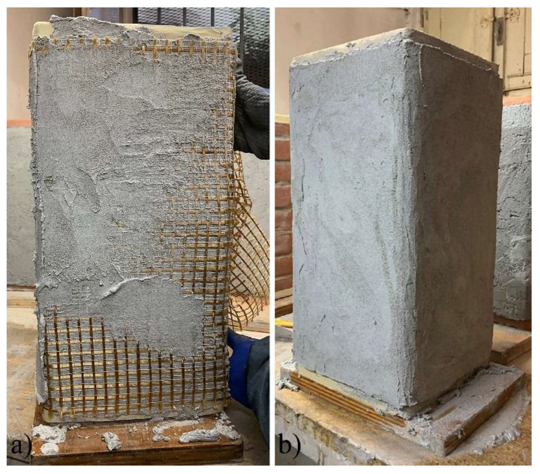
2.2.2. Mechanical Characterization of FRLM Composites
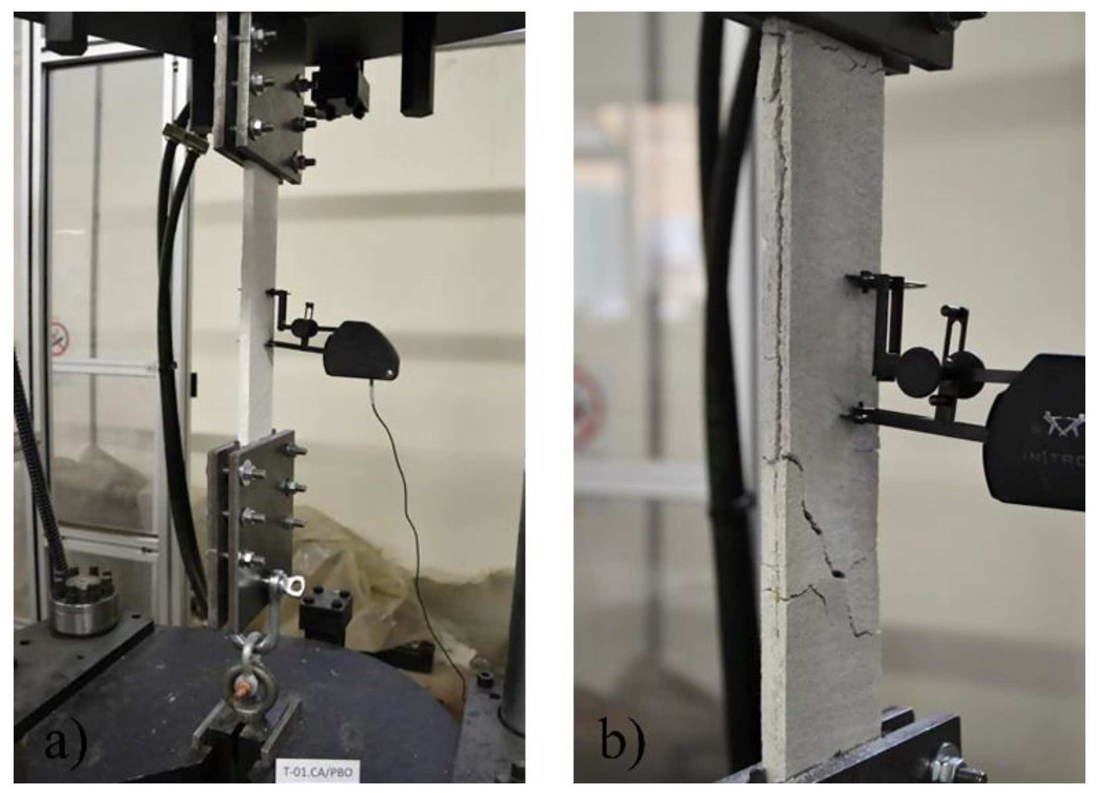
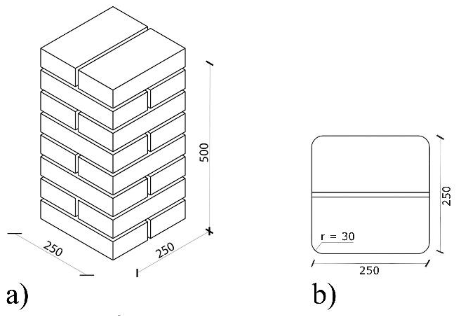
2.2.3. Mechanical Characterization of Columns
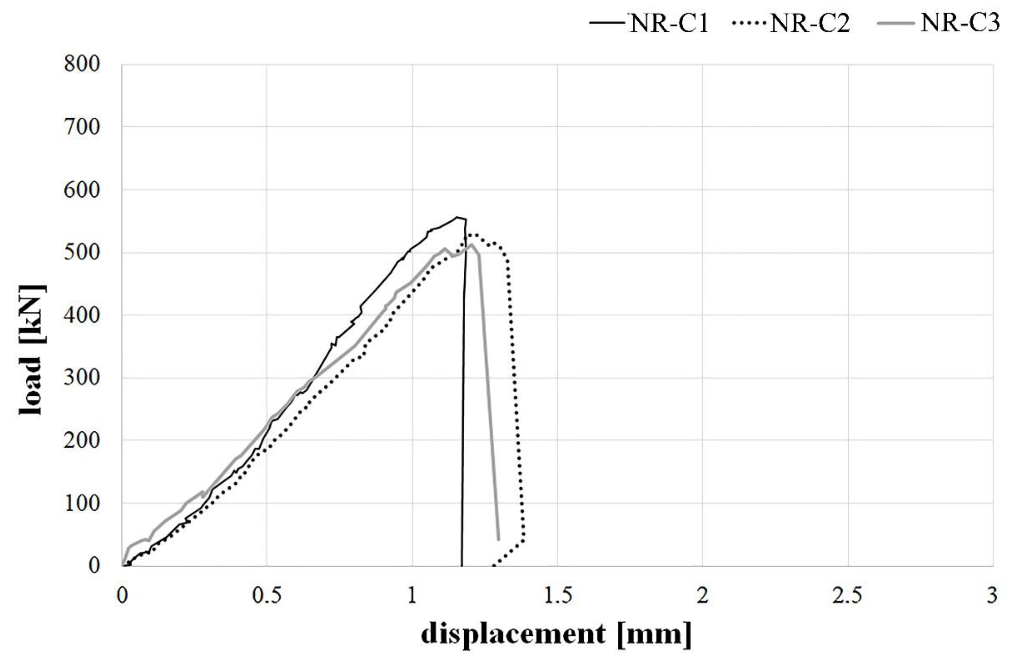
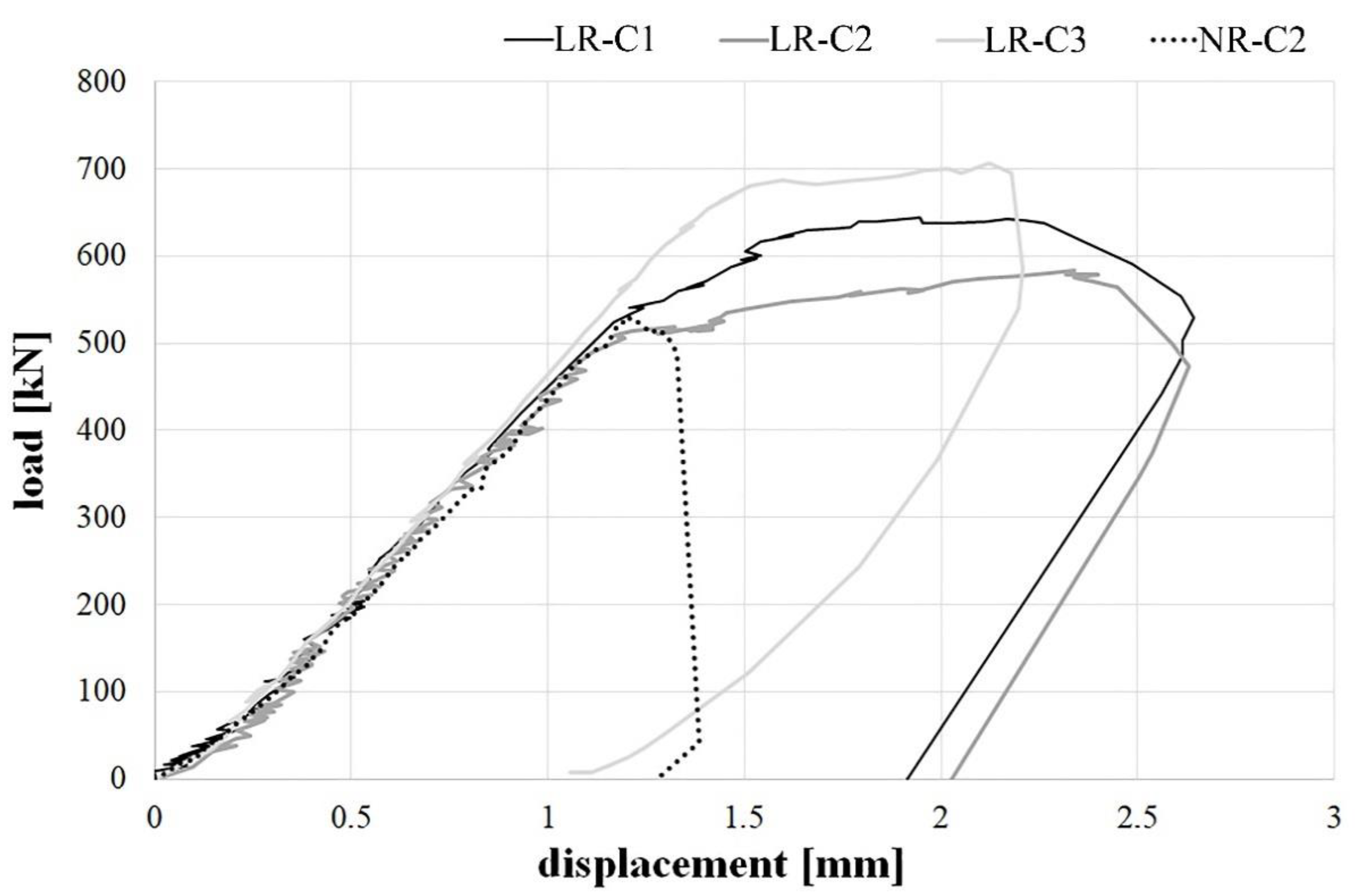
3. Results
4. Discussion
5. Conclusions
- FRLM composites made of a natural matrix with low mechanical properties can be effective for increasing the strength and the ductility of masonry columns—this second aspect is crucial in the case of historical buildings located in seismic areas;
- As a consequence of the previous point, an FRLM composite was shown to be a good strengthening solution in the case of interventions on columns of historical buildings where compatibility between new and original materials is a specific requirement;
- The equations currently present in the literature were demonstrated to be able to fit the experimental outcomes of many researcher’s investigations, where mortar used to form the composite had good mechanical properties, largely higher than those of the mortar joints of the column;
- As a result of the present investigation, the same equations present in the literature were not able to correctly predict the effectiveness of the used composite in increasing the strength of the confined columns; this result, probably, depends on the low mechanical properties of mortar which directly influence the formula with respect to confinement pressure;
- A further effort should be made by researchers to take into account the contribution of the composite wrap in terms of ductility increase on confined members, this being a crucial factor in seismic areas.
Author Contributions
Funding
Institutional Review Board Statement
Informed Consent Statement
Conflicts of Interest
References
- Alecci, V.; Ayala, A.; De Stefano, M.; Marra, A.; Nudo, R.; Stipo, G. Influence of the masonry wall thickness on the outcomes of double flat-jack test: Experimental and numerical investigation. Constr. Build. Mater. 2021, 285, 122912. [Google Scholar] [CrossRef]
- Alecci, V.; De Stefano, M.; Luciano, R.; Marra, A.M.; Stipo, G. Numerical Investigation on the Use of Flat-Jack Test for Detecting Masonry Deformability. J. Test. Eval. 2020, 49, 537–549. [Google Scholar] [CrossRef]
- Giresini, L.; Stochino, F.; Sassu, M. Economic vs environmental isocost and isoperformance curves for the seismic and energy improvement of buildings considering Life Cycle Assessment. Eng. Struct. 2021, 233, 111923. [Google Scholar] [CrossRef]
- Beconcini, M.L.; Cioni, P.; Croce, P.; Formichi, P.; Landi, F.; Mochi, C. Non-linear static analysis of masonry buildings under seismic actions. In Proceedings of the 12th International Multi-Conference on Society, Cybernetics and Informatics (IMSCI 2018), Orlando, FL, USA, 8–11 July 2018; Callaos, N., Ed.; International Institute of Informatics and Systemics (IIIS): Orlando, FL, USA, 2020; pp. 126–131. [Google Scholar]
- de Falco, A.; Giresini, L.; Sassu, M. Temporary Preventive Seismic Reinforcements on Historic Churches: Numerical Modeling of San Frediano in Pisa. Appl. Mech. Mater. 2013, 351–352, 1393–1396. [Google Scholar] [CrossRef]
- Croce, P.; Beconcini, M.L.; Formichi, P.; Cioni, P.; Landi, F.; Mochi, C.; Giuri, R. Influence of mechanical parameters on non-linear static analysis of masonry buildings: A relevant case-study. Procedia Struct. Integr. 2018, 11, 331–338. [Google Scholar] [CrossRef]
- Borri, A.; Grazini, A. Masonry columns strengthening with FRP materials. In Proceedings of the 2nd Congress on Mechanics of Masonry Structures Strengthened with FRP-Materials: Modeling, Testing, Design, Control, Venice, Italy; Ceriolo, L., Zerbo, V., Eds.; Cortina Ed.: Padova, Italy, 2004; pp. 193–202. [Google Scholar]
- Corradi, M.; Grazini, A.; Borri, A. Confinement of brick masonry columns with CFRP materials. Compos. Sci. Technol. 2007, 67, 1772–1783. [Google Scholar] [CrossRef]
- Krevaikas, T.D.; Triantafillou, T. Masonry Confinement with Fiber-Reinforced Polymers. J. Compos. Constr. 2005, 9, 128–135. [Google Scholar] [CrossRef]
- Campione, G.; Miraglia, N. Strength and strain capacities of concrete compression members reinforced with FRP. Cem. Concr. Compos. 2003, 25, 31–41. [Google Scholar] [CrossRef]
- Mander, J.B.; Priestley, M.J.N.; Park, R. Theoretical Stress-Strain Model for Confined Concrete. J. Struct. Eng. 1988, 114, 1804–1826. [Google Scholar] [CrossRef] [Green Version]
- Alecci, V.; Barducci, S.; De Stefano, M.; Galassi, S.; Luciano, R.; Rovero, L.; Stipo, G. Reliability of Different Test Setups and Influence of Mortar Mixture on the Fabric-Reinforced Cementitious Matrix-to-Brick Bond Response. J. Test. Eval. 2021, 49, 4476–4495. [Google Scholar] [CrossRef]
- Barducci, S.; Alecci, V.; De Stefano, M.; Misseri, G.; Rovero, L.; Stipo, G. Experimental and Analytical Investigations on Bond Behavior of Basalt-FRCM Systems. J. Compos. Constr. 2020, 24, 04019055. [Google Scholar] [CrossRef]
- Minafò, G.; La Mendola, L. Experimental investigation on the effect of mortar grade on the compressive behaviour of FRCM confined masonry columns. Compos. Part B Eng. 2018, 146, 1–12. [Google Scholar] [CrossRef]
- Murgo, F.; Mazzotti, C. Masonry columns strengthened with FRCM system: Numerical and experimental evaluation. Constr. Build. Mater. 2019, 202, 208–222. [Google Scholar] [CrossRef]
- Cascardi, A.; Micelli, F.; Aiello, M.A. FRCM-confined masonry columns: Experimental investigation on the effect of the inorganic matrix properties. Constr. Build. Mater. 2018, 186, 811–825. [Google Scholar] [CrossRef]
- Richart, F.E.; Brandtzaeg, A.; Brown, R.L. The Failure of Plain and Spirally Reinforced Concrete in Compression; Engineering Experimental Station 1929, Bulletin n. 190; University of Illinois: Urbana, IL, USA, 1929; pp. 3–72. [Google Scholar]
- Richart, F.E.; Brandtzaeg, A.; Brown, R.L. A Study of the Failure of Concrete under Combined Compressive Stresses; Engineering Experimental Station 1928, Bulletin n. 185; University of Illinois: Urbana, IL, USA, 1928; pp. 3–102. [Google Scholar]
- Zampieri, P. Horizontal capacity of single-span masonry bridges with intrados FRCM strengthening. Compos. Struct. 2020, 244, 112238. [Google Scholar] [CrossRef]
- Cascardi, A.; Dell’Anna, R.; Micelli, F.; Lionetto, F.; Aiello, M.A.; Maffezzoli, A. Reversible techniques for FRP-confinement of masonry columns. Constr. Build. Mater. 2019, 225, 415–428. [Google Scholar] [CrossRef]
- Krevaikas, T.D. Experimental study on carbon fiber textile reinforced mortar system as a means for confinement of masonry columns. Constr. Build. Mater. 2019, 208, 723–733. [Google Scholar] [CrossRef]
- Balsamo, A.; Cascardi, A.; Di Ludovico, M.; Aiello, M.A.; Morandini, G. Analytical study on the effectiveness of the FRCM-confinement of masonry columns. In Proceedings of the 7th Euro-American Congress on Construction Pathology, Rehabilitation Technology and Heritage Management (Rehabend 2018), Càceres, Spain, 15–18 May 2018; pp. 1–9. [Google Scholar]
- CNR-DT 215/2018. Istruzioni per la Progettazione, l’Esecuzione ed il Controllo di Interventi di Consolidamento Statico Mediante L’utilizzo di Compositi Fibrorinforzati a Matrice Inorganica; Commissione di Studio per la Predisposizione e L’analisi di Norme Tecniche Relative Alle Costruzioni: Roma, Italy, 2018. [Google Scholar]
- UNI EN 772-1. Metodi di Prova per Elementi per Muratura—Parte 1: Determinazione della Resistenza a Compressione; Ente Nazionale Italiano di Unificazione (European Committee for Standardization): Milan, Italy, 2015. [Google Scholar]
- UNI EN 1015-11. Metodi di Prova per Malte per Opere Murarie—Determinazione della Resistenza a Flessione e a Compressione della malta Indurita; Ente Nazionale Italiano di Unificazione (European Committee for Standardization): Milan, Italy, 2007. [Google Scholar]
- Arboleda, D.; Carozzi, F.G.; Nanni, A.; Poggi, C. Testing Procedures for the Uniaxial Tensile Characterization of Fabric-Reinforced Cementitious Matrix Composites. J. Compos. Constr. 2016, 20, 04015063. [Google Scholar] [CrossRef]
- De Santis, S.; Hadad, H.A.; Basalo, F.D.C.Y.; De Felice, G.; Nanni, A. Acceptance Criteria for Tensile Characterization of Fabric-Reinforced Cementitious Matrix Systems for Concrete and Masonry Repair. J. Compos. Constr. 2018, 22, 04018048. [Google Scholar] [CrossRef]
- Bernat-Maso, E.; Gil, L.; Mercedes, L.; Escrig, C. Mechanical properties of pre-stressed fabric-reinforced cementitious matrix composite (PFRCM). Constr. Build. Mater. 2018, 191, 228–241. [Google Scholar] [CrossRef]
- Focacci, F.; D’Antino, T.; Carloni, C. The role of the fiber–matrix interfacial properties on the tensile behavior of FRCM coupons. Constr. Build. Mater. 2020, 265, 120263. [Google Scholar] [CrossRef]
- Lignola, G.P.; Caggegi, C.; Ceroni, F.; De Santis, S.; Krajewski, P.; Lourenço, P.B.; Morganti, M.; Papanicolaou, C.; Pellegrino, C.; Prota, A.; et al. Performance assessment of basalt FRCM for retrofit applications on masonry. Compos. Part B Eng. 2017, 128, 1–18. [Google Scholar] [CrossRef]
- Carozzi, F.G.; Bellini, A.; D’Antino, T.; De Felice, G.; Focacci, F.; Hojdys, Ł.; Laghi, L.; Lanoye, E.; Micelli, F.; Panizza, M.; et al. Experimental investigation of tensile and bond properties of Carbon-FRCM composites for strengthening masonry elements. Compos. Part B Eng. 2017, 128, 100–119. [Google Scholar] [CrossRef]
- Sneed, L.H.; Baietti, G.; Fraioli, G.; Carloni, C. Compressive Behavior of Brick Masonry Columns Confined with Steel-Reinforced Grout Jackets. J. Compos. Constr. 2019, 23, 04019037. [Google Scholar] [CrossRef]
- Alecci, V.; Focacci, F.; Rovero, L.; Stipo, G.; De Stefano, M. Extrados strengthening of brick masonry arches with PBO–FRCM composites: Experimental and analytical investigations. Compos. Struct. 2016, 149, 184–196. [Google Scholar] [CrossRef]
- Aiello, M.; Bencardino, F.; Cascardi, A.; D’Antino, T.; Fagone, M.; Frana, I.; La Mendola, L.; Lignola, G.; Mazzotti, C.; Micelli, F.; et al. Masonry columns confined with fabric reinforced cementitious matrix (FRCM) systems: A round robin test. Constr. Build. Mater. 2021, 298, 123816. [Google Scholar] [CrossRef]


| Material | Compression Strength (MPa) (Standard Deviation; CoV) | Flexural Tensile Strength (MPa) (Standard Deviation; CoV) |
|---|---|---|
| Brick | 17.10 (0.84; 0.05) | 5.60 (0.58; 0.10) |
| Cement–lime mortar joint | 2.92 (0.18; 0.06) | 0.44 (0.07; 0.16) |
| Material | Compression Strength fc,mat (MPa) | Flexural Tensile Strength ft (MPa) |
|---|---|---|
| (Standard Deviation; CoV) | (Standard Deviation; CoV) | |
| Lime-based mortar | 0.79 | 0.64 |
| (0.12; 0.15) | (0.02; 0.03) |
| Material | σt | Ef | εuf |
|---|---|---|---|
| (MPa) | (MPa) | ||
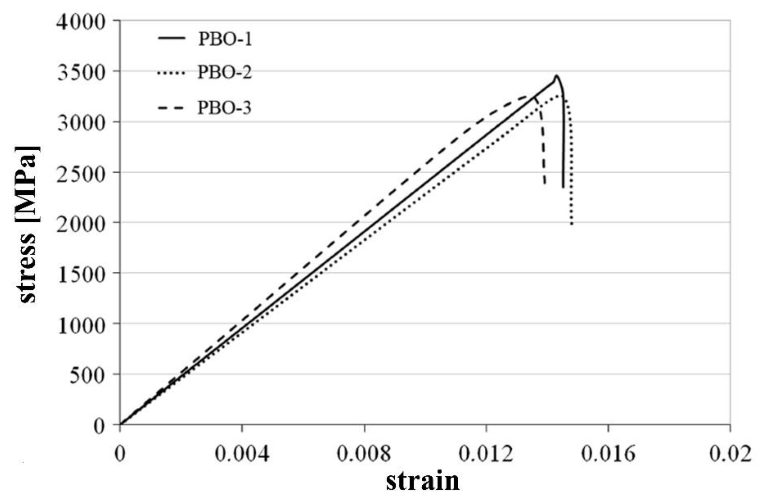
| PBO | 3300 * | 270,000 * | 0.0149 * |
| 5800 ** | 282,000 ** | 0.025 ** |
| Specimen | Fmax (N) | dmax | σ (MPa) | εmax |
|---|---|---|---|---|
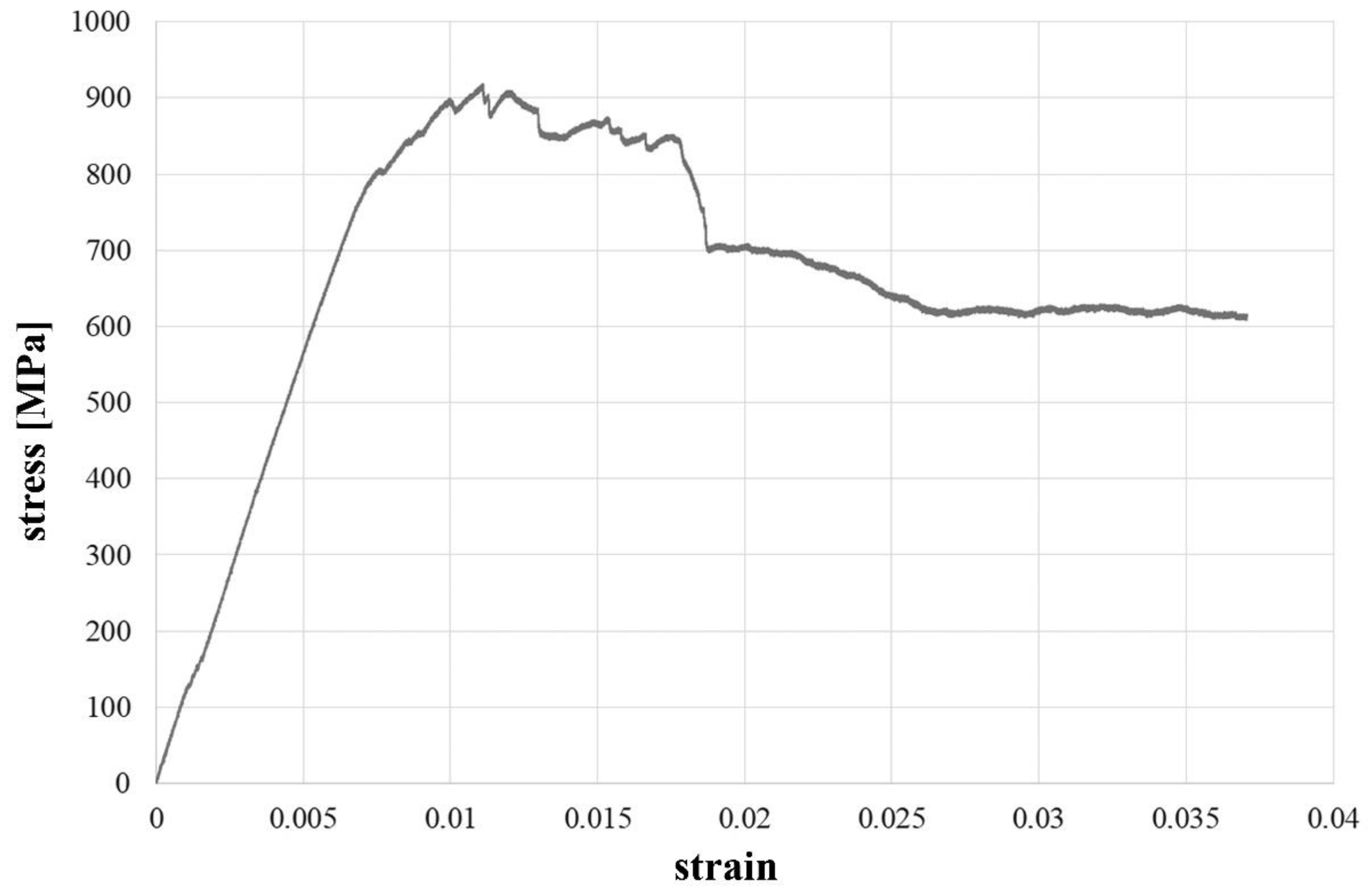
| T-01.CA/PBO | 835.83 | 2.89 | 918.49 | 0.012 |
| T-02.CA/PBO | 800.19 | 2.83 | 879.33 | 0.011 |
| T-03.CA/PBO | 826.02 | 2.85 | 907.71 | 0.010 |
| ID Specimen | Fmax | σC | μu |
|---|---|---|---|
| (kN) | (MPa) | ||
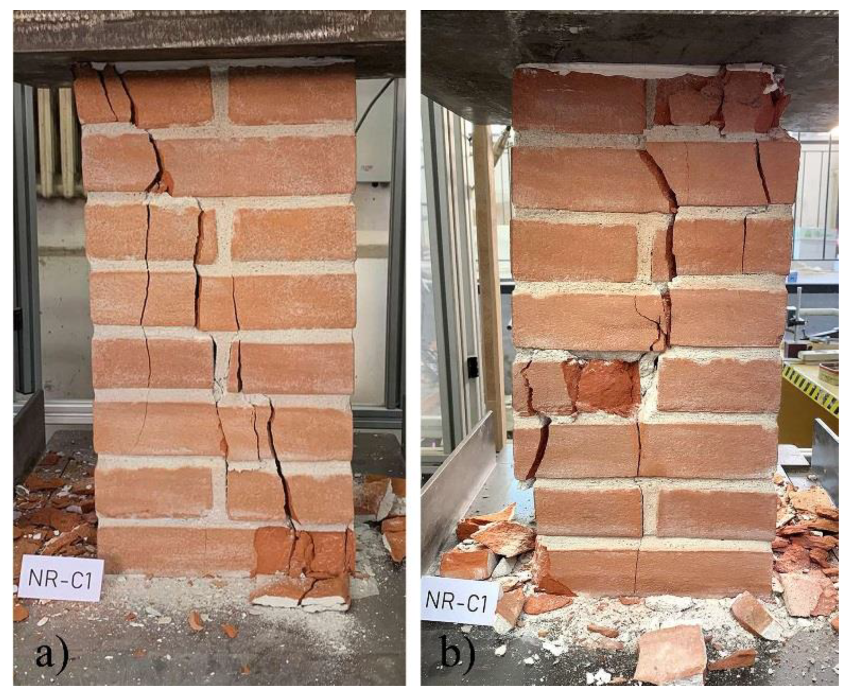
| NR-C1 | 556.35 | 8.90 | 1.02 |
| NR-C2 | 529.65 | 8.47 | 1.14 |
| NR-C3 | 512.04 | 8.19 | 1.15 |
| Average | 532.68 | 8.52 | 1.10 |
| LR-C1 | 643.75 | 10.30 | 1.86 |
| LR-C2 | 583.36 | 9.33 | 2.11 |
| LR-C3 | 706.34 | 11.30 | 1.52 |
| Average | 594.43 | 10.31 | 1.83 |
Publisher’s Note: MDPI stays neutral with regard to jurisdictional claims in published maps and institutional affiliations. |
© 2021 by the authors. Licensee MDPI, Basel, Switzerland. This article is an open access article distributed under the terms and conditions of the Creative Commons Attribution (CC BY) license (https://creativecommons.org/licenses/by/4.0/).
Share and Cite
Alecci, V.; De Stefano, M.; Galassi, S.; Magos, R.; Stipo, G. Confinement of Masonry Columns with Natural Lime-Based Mortar Composite: An Experimental Investigation. Sustainability 2021, 13, 13742. https://0-doi-org.brum.beds.ac.uk/10.3390/su132413742
Alecci V, De Stefano M, Galassi S, Magos R, Stipo G. Confinement of Masonry Columns with Natural Lime-Based Mortar Composite: An Experimental Investigation. Sustainability. 2021; 13(24):13742. https://0-doi-org.brum.beds.ac.uk/10.3390/su132413742
Chicago/Turabian StyleAlecci, Valerio, Mario De Stefano, Stefano Galassi, Raymundo Magos, and Gianfranco Stipo. 2021. "Confinement of Masonry Columns with Natural Lime-Based Mortar Composite: An Experimental Investigation" Sustainability 13, no. 24: 13742. https://0-doi-org.brum.beds.ac.uk/10.3390/su132413742