1. Introduction
Building Information Modeling (BIM) is a disruptive methodology in building and civil engineering infrastructure management, covering all stages of the structure’s life cycle. As established by the National BIM Standard-United States, a BIM model “is a digital representation of physical and functional characteristics of a facility, and it serves as a shared knowledge resource for information about a facility, forming a reliable basis for decisions during its life cycle from inception onward” [
1]. This methodology allows a concurrent access to a cloud-based model of the infrastructure by all agents involved in its conception. This reduces the need to transfer the information between the different agents and stakeholders, reducing the errors due to misinterpretation. In addition, it also accelerates the production process [
2,
3]. The generalization of BIM has begun in the building sector, and there is a consensus that it will be extended in the short- and medium-term to other infrastructures, including roads.
1.1. Building Information Modeling for Civil Engineering
Initially, the BIM model was created in the AECO industry (architecture, engineering, construction, and operations sectors) to be applied in the building sector, but rapidly has expanded to other areas of construction, such as civil—bridges, tunnels, airports, ports and mines, and transportation—roads and highways, railways and mass transit infrastructures [
4].
There are an important number of agents and stakeholders that could benefit from the BIM model’s advantages, such as planners, engineers, designers, safety specialists, contractors, risk managers, etc., so there are multiple international initiatives to promote the use of this technology. In countries like the United States, Sweden or Australia, public administrations already require BIM in public building projects, while other countries are adopting similar strategies [
5]. The European Commission has launched the EUBIM Task Group initiative [
6], with the participation of Member States to align the different initiatives to implement BIM technology. By countries, in Finland, Norway and Sweden, its use is mandatory from 2007–2010 in building, while in the Netherlands, it was adopted in 2012. The United Kingdom launched a plan in 2011 with the goal of reducing construction project costs by 20%, for which the BIM is mandatory in public tenders as of 2016. In France, its plan was launched in 2014 and sets a mandatory use of BIM from 2017 on building. Germany launched its strategy in 2015, driven by the private sector and supported by the government through a series of pilot works. In Spain, the BIM initiative has been launched with the objective of increasing the productivity within the construction sector [
5].
1.1.1. Open Formats for BIM
To allow the exchange of data, universal and open formats should be used. The term Open BIM refers to “a collaborative approach to the design and construction of buildings based on standards and open workflows” [
7]. The main objective of Open BIM is to streamline the exchange of data between all the actors involved in creating a BIM model that covers all possible fields of application. From design to construction, from the operation of the building to its demolition and the recycling of components and materials, at the end of the life cycle of the structure. Thus, an essential requirement for Open BIM is the use of open and neutral data formats.
The Industry Foundation Classes (IFC) format is the best-known solution for Open BIM. This format allows the exchange of an informative model, without loss or distortion of data and information [
8], and has been recognized as an international standard for the exchange of models and informative content of BIM. IFC has undergone several development cycles since its inception in 1995. There have been more than a dozen versions from IFC1 to the current IFC4 (including ifcXML and IFCzip versions). IFC4 Add 1 was officially released in July 2015, but it took a few years to be implemented in the software industry. Since 2018,
buildingSMART International has focused on the implementation of IFC4, testing and certification of the import and export capacity by software solutions. Since IFC4 software certification is still in progress, IFC2X3, originally released in 2006, remains the most IFC version used. IFC is registered as an official international standard ISO 16739-1:2018 that includes definitions covering data required for buildings and infrastructure assets over their life cycle [
9]. The IFC format is intended for the exchange of data between different software, during the development of the design, construction, management, and maintenance phases.
Thus, it is possible to consider the IFC as an exchange file that allows transferring geometries and metadata between applications: the objects will have a precise placement in space and will be differentiated hierarchically in categories, characteristics, and functions. As an open format, it is free and well documented, so software vendors can ensure interoperability.
The IFC schema can be expressed in diverse file formats, usually in Standard for the Exchange of Product model (STEP) as IFC-SPF, also as eXtensible Markup Language (XML), the American Standard Code for Information Interchange (ASCII), or a ZIP file:
IFC-SPF is a text format in the EXPRESS data modeling language. It has compact dimensions and is the most widely used IFC format.
IFC-XML is an extensible markup language format, XML. While XML is a more common programming lexicon, IFC-XML has a larger file dimension than IFC-SPF and is less used.
IFC-ZIP is a ZIP-included format of the IFC-SPF file. An ifcZIP file typically compresses an .ifc to 60–80% and an .ifcXML to 90–95%.
In the field of architecture and construction, Open BIM technology has been adopted as a starting point to design a possible specification. Nevertheless, there is no specification of IFC files currently, or standardized interchange format from the BIM technology to store enough information on roads and their environment. Different authors have outlined that BIM could help in assisting risk assessment and construction processes of different transportation infrastructures, basically in the design, planning, maintenance and safety analysis of roads and highways [
10,
11,
12,
13]. Bradley et al. [
14] highlights the use of BIM models in highway development due to the advantages of integrating visual and non-graphical data into the model during the pre-construction and construction phases. Additionally, several authors have reviewed the importance of BIM integration with Internet of Things (IoT) sensors (proximity or lighting), considering different data sources to provide real-time feedback to infrastructure workers [
15].
There is currently an active line of research in the scientific community that is exploring the potential of integration between BIM models and the GIS platform in the transport infrastructure design process [
16,
17], or the integration of BIM models on road and pavement structural analysis [
13]. Nevertheless, according to Costin et al. [
4], the use of BIM models in the design of transportation infrastructures—such as roads and highways—has increased notably in recent years, but still needs a greater research effort from academia and industry for the definition of the IFC data file content that could improve their interoperability between different stakeholders. A vast research effort in the maintenance, management, safety assessment and sustainability for these infrastructures is also required [
14].
1.1.2. The RoadBIM Project
In this line, the project “Design and development of BIM technologies for validation and management of road construction projects, their exploitation and the safety management of road infrastructure-RoadBIM” (EXP-00091379/ITC-20161077), funded by the Spanish Center for Industrial Technological Development (CDTI) and the 2014–2020 FEDER Interconecta Program, was developed. In this project, several companies (SACYR, APLITOP, APOGEA, and TYPSA) worked together with the collaboration of the Universitat Politècnica de València (UPV). The main goal of the RoadBIM Project was the expansion of BIM technology to the integral development of road projects, thus facilitating the different phases of the productive activity and allowing significant efficiency gains, by being able to obtain, interpret, exploit, and manage project information.
A specific aim of the RoadBIM project was to define an IFC-based exchange format with which computer applications could develop/import/export road projects. Its universal scope would allow any software (already existing or developed in the future) to interpret the information that at different project stages were added to the BIM model. With BIM, additional road-related variables (such as road safety, traffic, level of service, operating speed, visibility, etc.) can be incorporated to the road project development process in an automated and universal way.
In addition, one of the main RoadBIM project objectives was to define a methodology for the use of driving simulators as a tool for road safety analysis throughout the BIM model, allowing a fast recreation of the driving virtual scenario corresponding to the road.
These scenarios can reproduce an existing or non-existing road section in the design phase, allowing the study of driver behavior in both cases. Thus, road designs can be improved from the very beginning, reducing the need for corrective actions once the road has been built. This approach can be also used to identify safety concerns on existing roads, where volunteers can run the simulator and have their performance parameters recorded in depth.
2. Literature Review on the Application of Driving Simulators in Road Safety Analysis
The analysis of road safety is key in road design, which aims to ensure a consistent layout and thus reduce the likelihood of crash occurrence. Driving simulators represent a very interesting and effective tool to incorporate human factors in road safety. One of the most important processes is the road safety analysis (RSA) [
18,
19], where highway engineers and auditors can generate virtual scenarios, along which they—or volunteers—can test road designs.
The use of advanced driving simulators to study aspects related to geometric design offers many other positive strengths, such as [
20]:
Greater versatility: Simulators allow the reconstruction of roads (new or existing) using different configurations in terms of horizontal and vertical alignment and cross-section, as well as for different pavement conditions.
Low cost of the experiments: While the cost of acquiring the simulators is medium or high, the costs of modeling the scenario, the use of the simulator, the tests of the drivers, the researchers and other personnel related to the experiment are relatively low.
Absence of difficulties in data collection: Data recording is extremely efficient since they are automatically collected while driving in the simulator at intervals less than or equal to a second or a meter. The most common parameters are trajectory, speed, and accelerations.
Low risk: The use of simulators guarantees the performance of the experiment under controlled conditions, which allows total safety for drivers who carry out the test. This allows evaluating designs that, in the field, might have a high risk for drivers or present a high difficulty of data collection.
There have been many researchers who have used driving simulators to study the influence of geometric design on driver’s behavior [
21]. These studies have been based on the analysis of the horizontal and vertical alignment coordination, intersections, interchanges and acceleration and deceleration lanes, overtaking maneuver, operation speed, cross-section, path on horizontal curves, visual demand, road safety countermeasures, signaling and consistency of the geometric design. However, the most recent research linked to driving simulators focuses on aspects closely related to road geometric design and road safety assessment [
22,
23,
24,
25].
Lee et al. [
26] developed a methodology to properly use the driving simulator in conducting road geometric design studies. Their method was based on the correct identification of the design problem to be analyzed, and relating it to the driving simulator constructive characteristics. This problem does not have a simple solution because the operational and budgetary restrictions of the research might influence the selection of necessary hardware and software components.
Finally, a driving simulator must be rigorously validated prior to its use [
27,
28,
29,
30,
31]. The validation process compares the results obtained from the simulator to the corresponding real-world parameters, determining whether the simulator outputs can be assumed to be similar—or transformable—to reality. The level of realism of a simulator affects its validation process. A greater level of realism would presumably present more chances of being valid or would require simpler transformations.
2.1. Methodology for Road Safety Analysis with Driving Simulators
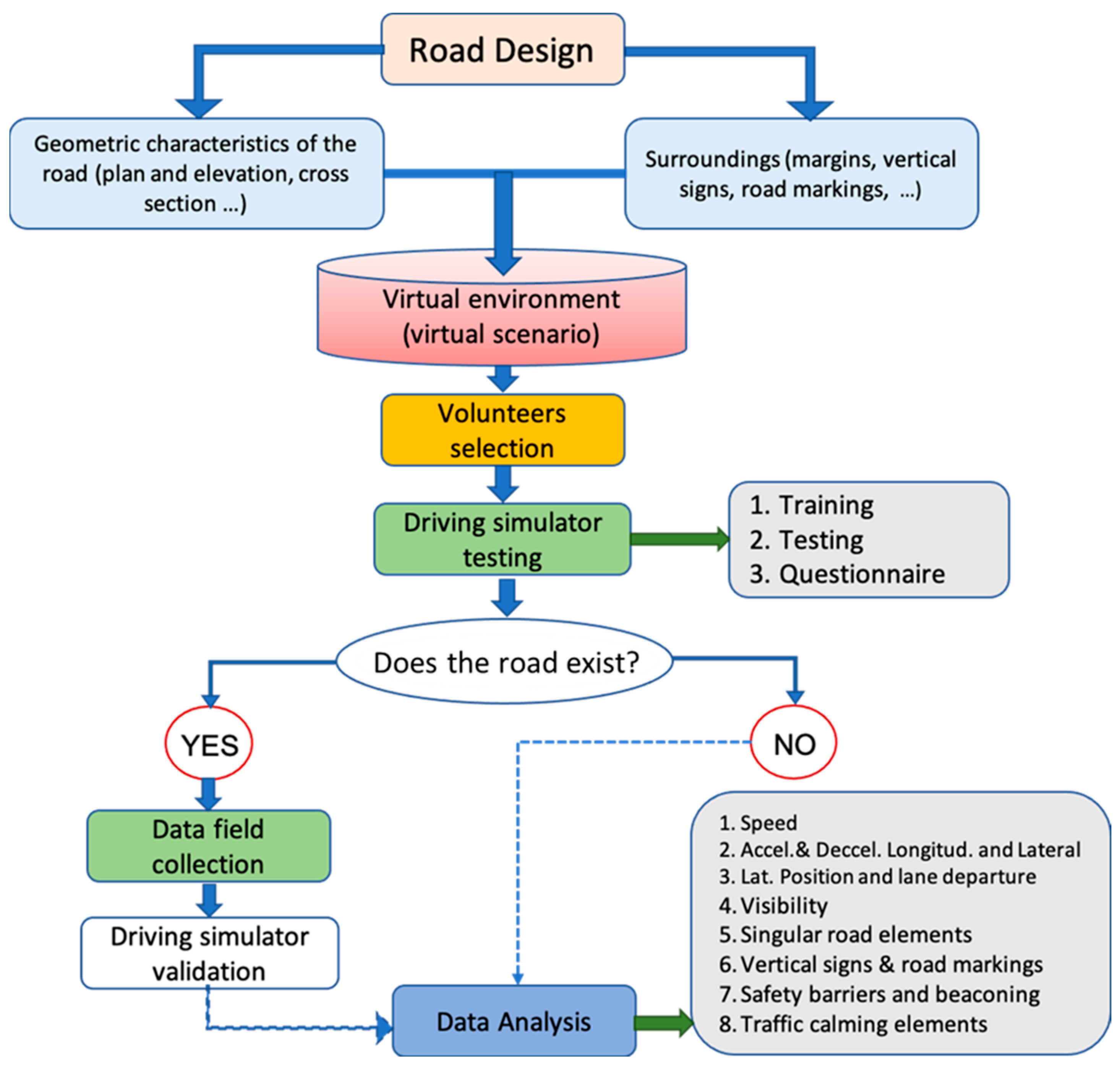
Considering the previous aspects, the authors have recently proposed a new methodology for road safety analysis using driving simulators (
Figure 1) [
30,
32]. In the first step, the road geometric characteristics—alignment, elevation and cross-section, as well as the environment (side margins, vertical signs, road markings, surroundings, etc.) must be obtained from the design phase. From this information, the virtual scenario can be recreated and loaded into the driving simulator. In the next step, a group of volunteers (who must be representative), will travel through the virtual scenario using the simulator.
Additionally, and only when the road already exists, the operational data of realistic driving from this existing road can be compared with the operation carried out by these volunteers onto the driving simulator. This can be used to validate the simulator, that is, to detect if the output data obtained from it are comparable to reality. Field study operational data are generally collected by non-invasive devices such as video cameras and LIDAR.
The comparison between the simulator and the real environment data will be focused on variables as speed, longitudinal and transverse acceleration and deceleration, lateral position, and lane departure. In addition to the geometric characteristics, the driver’s behavior can also be analyzed against variations in the following variables: existing visibility, singular road elements, vertical signs and road markings, safety barriers and beaconing, and traffic calming elements.
The process for designing a Virtual Reality (VR) scenario to be carried out in road safety analysis is considered by experts a real bottleneck and one of the most critical steps in preparing the experiments [
33] (
Figure 1). The scenario characteristics to be modeled (road alignment, cross-section, superstructure, geographical environment, environmental conditions, types of vehicles and drivers involved, type of simulator to be implemented, etc.) will determine the accuracy of the model and therefore the success of the analysis, design assessment or experiments to be carried out.
2.2. Driving Simulator Scenarios for Road Safety Analysis
In relation to the simulation environment, there is a broad consensus in the scientific community regarding the importance of the software that represents the virtual reality simulation environment [
11,
34]. This must be realistic enough so that the context in which this simulation takes place allows a good interaction with the subjects who are going to use it, reflecting a level of detail of the scene that facilitates optimal decision-making and a bidirectional feedback between trainees and the VR scene [
35].
The conceptual design of a virtual reality (VR) scenario with a certain degree of complexity, should meet three basic recommendations [
36]:
Each part of the scenario should be created and designed separately.
The different parts of the scenario should be developed in rapid iterations, allowing exploration of different parameters and alternatives.
Requested scenario receptors should participate actively in the design process, collaborating with developers who will implement the source code.
Vahdatikhaki et al. [
35] established that the development of a VR scenario representing a civil infrastructure can be defined through a 4-phase process: “context capture”, “context generation”, “context-user interaction” and “context-based assessment”. The first phase aims at obtaining information on the data sources that will allow the design of the scenario environment. In these cases, aspects such as the Level of Detail (LoD) of the virtual environment is important, and it is directly related to the accuracy of the used sources. The data obtained from static sources—objects in which status does not change with the time, such as location, orientation, and geometry, or dynamic—objects in which status changes rapidly with the time, such as equipment or humans, can proceed from sensors, infrared cameras, laser or LiDAR scanners, Inertial Measurement Units (IMUS), GPS, aerial photogrammetry, and orthophotos. The use of BIM models can make a difference in this first phase for designing the virtual environment as they can integrate different data from different sources, saving cost and development time.
In the context-generation of the scene to be designed or analyzed, all information sources must be converted to a “virtualized” scenario. A basic condition of this second phase is that all sources must have very high precision and have to be processed so that the virtual environment is as realistic as possible. This phase of development is critical and constitutes a real bottleneck. To convert all data sources to a 3D model, Geographic Information System (GIS) platforms can be used, since they can integrate different types of data from sensors, cadastral data, and photogrammetry from public sources. This implies that both the buildings and their surroundings, adjacent roads and street network in the analyzed area could be imported and integrated into a GIS platform—such as City Geography Markup Language (CityGML) or Shapefiles, to be converted into different surfaces of data. In this process of conversion, BIM models can provide a major advance in terms of cost and sustainability of the project.
Finally, once the virtual scenario has been generated, it could start the “context-user interaction” phase. In this case, different human-computer media could be used for the immersive VR analysis, as head-mounted displays (HMD), joystick devices, head-eye trackers (HET) or simulator rigs [
37,
38,
39,
40,
41]. Depending on the chosen type of experimental tool, the capabilities of the transportation infrastructure analysis may be used to a greater extent in the last “context-based assessment” phase. In this last phase, it would be possible to develop safety analysis on rural roads or highways, by using metrics such as proximity, speed, or number of collisions, where the use of BIM models can reproduce virtual environments allowing significant economic cost-savings and improvements in the project productivity [
35,
42,
43].
Modeling the virtual scenario requires a high degree of personnel specialization in many areas—traffic, road design, road safety, among others—as well as graphic simulation skill techniques and 3D object modeling, to reproduce real-world conditions as good as possible.
To generate and run a VR scenario in a human-computer experimental tool—simulator, test rig and HMD, three developing steps can be identified: editing, programming, and processing.
2.2.1. Scenario Editing
The scenario editing consists in determining which elements will take part, as well as their properties and position. This is a very costly step in terms of hours, and it depends on the size of the virtual scene and the quality or realism searched for. In this sense, the development of an urban or interurban virtual scenario requires the generation of a map of heights for the field, defining the road axis dimensions, camber, orthophoto of the terrain, textures and positions of different objects desired as signs, trees, walls, safety barriers and vegetation.
Tools like 3DSmax or Blender are generally used to recreate urban and interurban scenarios. Alternatively, game graphics engines such as Unity or UDK can be used to simplify design tasks. However, these engines are not used in scenarios larger than 100 km2, since the cost and time of the personnel involved would be too high. Likewise, there are technical limitations. Such a large scenario requires excessive memory or suffers from floating point precision limitations. To avoid this, a hierarchical subdivision of the two-dimensional space must be done implementing a Level of Detail (LoD) system, which allows to view very distant areas while maintaining a controlled frame rate per second. In fact, the use of less powerful graphics cards can be enabled simply by changing the resolution index of these faces.
This first step is ideal to prepare the simulator to accept a universal IFC file format. Due to its universal orientation, any road design application should be able to read/write IFC files. The process for exporting a road environment in this format would indeed be part of the general process of a BIM model application representing an existing or non-existing horizontal transportation infrastructure.
2.2.2. Scenario Programming
The simulation software should have tools to pre-process the data and convert it to more efficient native simulator or VR tool files. This is a necessary step since the original formats are often not adequate for real-time access to information. These optimizations take the relevant information, hence reducing the size of the files. This preprocessing is carried out in several stages, controlled by different code scripts that must be programmed. Each script takes one or more input files and transforms them into other output files which will be the input for another script. This procedure of “cooking” or compiling all the source data is performed only once per scenario and will be higher or lower depending on the editing process.
In addition, driving simulators or VR tools present a simulation software with different operating characteristics and different hardware—type of cabin, audiovisual system, dynamic platform, driving systems, special equipment, etc. Sometimes, specific software has to be developed, if required for the experiments to be carried out. Every simulator or VR tool developer uses the programming libraries that they consider most suitable for graphic rendering, the simulation of physical contacts between objects, loading frequency of images and sounds, acquisition of input data, management of files and data format.
2.2.3. Scenario Processing
Finally, native files adapted to the specific simulator or VR tool are generated. Although each driving simulator implements its own pre-processing system for input information, nearly all of them have to perform the following functions:
Extract the information from the data source files that were previously compiled.
Depending on the type and size of the scenario, it may be necessary to perform a procedure to subdivide it into smaller areas to prevent greater load and saturation for the graphic resources. For example, using a Chunked Level of Detail (CLOD) system [
44].
For each zone, the geometry and textures for the graphics engine, the collision volumes and the lists of objects and entities for the simulation engine must be obtained.
The data is indexed and exported to a database in native simulator or VR tool formats to ensure quick access.
3. Objectives
One of the most important limitations in the development of virtual road scenarios is the diversity of input data, that may come from different sources and require specific adaptation. This fact avoids a fast scenario generation which is time- and resource-consuming. Thus, the objective of this research was to present a new framework consisting of a BIM model for recreating faster virtual driving scenarios from an IFC-based file. In this paper, this new framework is shown and compared with two other classic methods for developing driving simulator scenarios for road safety analysis.
This IFC-based file format was adapted from current IFC specifications, expanding its use to fully support existing and non-existing road infrastructures. By using it, an entire project could be exported to a single IFC-based file, which will also be the only input for the driving simulator. Regarding this, it was hypothesized that this new framework would significatively accelerate the scenario generation process, demonstrating the main advantages of an IFC-based BIM model procedure in terms of cost-savings and project productivity.
4. Materials and Methods
To compare the different virtual simulation scenario methodologies for road safety analysis, three cases are analyzed based on the following techniques:
Manual editing techniques.
Multilayer editing techniques.
Use of files in IFC-RoadBIM format.
This section describes the particularities of each one of these methods, whose case studies were developed by the authors. All these scenarios were modeled with research purposes [
30,
44,
45,
46] over 11 years (2009–2019). The following section, Results, will compare them in terms of personnel developing time and cost-saving advantages using, as variables, the scenario editing, programming, and processing cost-times, considering that as follows:
Editing time represents time spent on obtaining data and editing it with specific software.
Programming time represents time for preparing the data for a specific simulator.
Simulator processing time represents processing time to generate native files adapted to a specific simulator.
4.1. Case Study 1: Manual Editing Procedure
Traditionally, the manual edition technique of a driving simulation scenario requires the use of a general purpose and polygon-mesh modeling software. The software used to edit 3D meshes is usually Autodesk 3DS Max, Autodesk Maya or Blender, among others. Alternative graphic game engines could also be used, such as Unity or UDK, to simplify the design tasks. However, these engines are not valid for scenarios larger than 100 km2. In addition to cost and time restrictions, larger scenarios would require excessive memory and might present limitations related to floating-point precision.
Both the road and the environment are modeled by zones trying to reproduce the real environment but taking into account the processing limitation of the computer that will run the simulation. To do that, different tools and editors are available. These applications work with the most common formats: OBJ, STL, FBX, MAX, or BLEND. At the same time, the geometry must be endowed with textures. In this case, it is necessary to use image processing tools such as Adobe Photoshop or GIMP. The typical formats for storing images are usually JPG, PNG, PSD or XCF.
The graphic model also has to be converted to a format supported by the simulator. This implies a software development to implement format conversion tools. For example, if the simulator only supports images in JPG format, the process of converting to JPG from any other data source has to be automated. The same happens with road geometry: the road design must be converted to polygonal meshes readable by the simulator software. Obviously, a previous determination of the minimum required formats would fasten this step.
A manual scenario editing requires a high resource consumption (h/people), being impractical for large environments. This resource allocation increases with the realism requirements and the size of the virtual scenario. In addition to this, human intervention ensures a very high level of detail, requiring just a few formats and minimum software development.
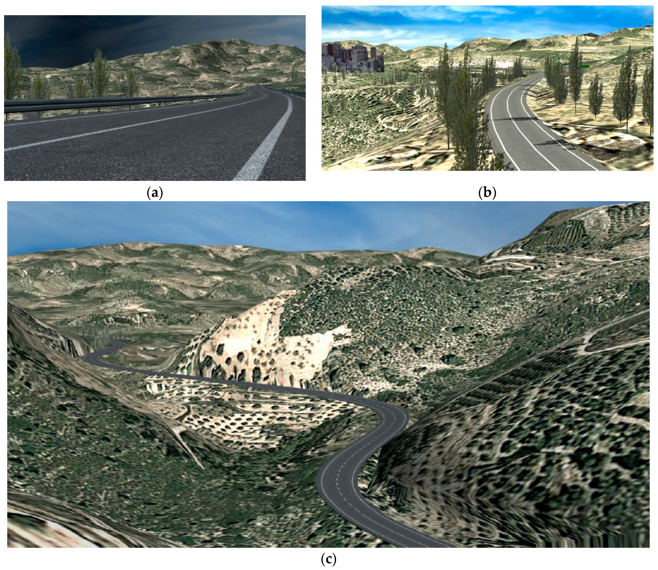
In this first case study, a two-lane rural road of 7.4 km was recreated by the authors using this methodology [
45]. A high level of realism and accuracy was achieved not only for road alignment, visibility, road markings and vertical signs, but also for the textures and elements of the environment. The road had a 10 m cross-section (3.5 m lane width and 1.5 m shoulder width). The delineation width, 100 mm, followed the Spanish road marking standard. The minimal radius of the horizontal curves was 265 m, and the corresponding superelevation rate was 7%. In this case, the simulated environment was used to study the effect of vertical crest curves overlapped with horizontal curves on drivers’ perception and behavior. Thus, the simulated environment was placed on real cartography, but the road alignment was entirely new.
Figure 2 shows several captured images from the recreated virtual scenario.
Fifty drivers were involved in the driving simulator experiments. These drivers were selected according with the age distribution of the licensed drivers in Spain in five-year intervals. Two of them were excused from completing the experiment because of simulator sickness discomfort, leaving 21 women and 27 men ranging in age from 20 to 73 years. The procedure at the driving simulator started with explanations about how to use the steering wheel and pedals, manual gear shift and other controls. After that, each participant filled a form to provide personal information and driving data, such as driving experience, km per year, rural road driving or urban area driving. The training session was executed on a rural road for approximately five minutes. The following driving session was carried out on the study road section. The round trip typically took 10 to 15 min. After driving the study road section, the driver had to fill out a second questionnaire about the driving experience, i.e., trip duration, mean speed, road conditions and the scenario. The drivers were also asked to rank 10 still images of studied curves by sharpness and available sight distance.
The driving scenario was performed manually by one person and took approximately 6 months of work on a basis of 37.5 h/week. That is, the total amount of time needed for manually developing the scenario was approximately 900 h. This means, in fact, that the time needed for developing a kilometer of driving scenario was approximately 122 h/km for the editing process. The programming time for preparing the data for the specific simulator was approximately 3 weeks, equivalent to 112.5 h. The ratio per scenario kilometer was, therefore, 15.2 h/km. Finally, the time associated to the simulator processing was less than 1 day of work by a programmer (1.08 h/km). The total estimated time needed for developing a manually designed driving scenario with this method was approximately a ratio of 138 h/km.
4.2. Case Study 2: Multilayer Editing Procedure
A major goal for this procedure was to automatically extract the environment and road surfaces. The road surface could be extracted from the design project, but the terrain surface was, in many cases, too large for an efficient rendering. To enhance performance, a hierarchical subdivision of the two-dimensional space is proposed, to implement a Chunked Level of Detail (CLOD) system (see
Figure 3a). The two-dimensional nodes are updated in real-time as the camera moves, loading and unloading triangulations and reducing or increasing the level of detail depending on the distance to the camera (i.e., the vehicle). By joining all meshes with different resolutions, an anisotropic surface with a high density of polygons is generated in the vehicle’s environment (see
Figure 3b). The CLOD system allows the visualization of very distant areas while keeping the frame rate per second under control. In fact, the use of less powerful GPUs could be enabled by simply changing the resolution index of these meshes.
Instead of directly modeling all elements on a single model, the simulator takes several files with the different types of elements as input [
44]. These file types are:
Road design. The horizontal and vertical alignments and cross-section were provided in an Excel file with the X, Y, Z coordinates of the axis at constant stations (1 m), and heights and offsets for the lane and shoulder edges. This information was obtained from a road design in Civil 3D.
Terrain model of the surrounding area. This terrain should include the original cartography as well as the earthworks of the road to model (cuts and embankments). ASC and geotiff formats are supported.
Orthophotography of the area. It was downloaded, in ECW format, from public repository for LiDAR and Orthophotographs (National Plan of Aerial Orthophotography, NPAO).
Inventory of elements of the superstructure and the environment. These elements were provided in two formats:
- ○
Road signs, road markings, beacons and safety barriers were provided in an Excel file, indicating the stations where these should be located, as well as their direction and properties.
- ○
Vegetation was provided in a DWG file. These objects can neither be referred to a road station nor be part of the road project. These objects are needed to increase the realism of the simulated environment, as well as to limit sight distance mimicking the real road. The DWG file presents different layers for the different vegetation types. Trees are represented by points, while vegetation masses are implemented as polygons. The object properties indicate the size and density of the elements.
All files must present the same coordinate system. The single elements, such as signs, barriers, etc., are part of the simulator as a library, which can be updated with new items, if required.
All these scripts must be later compiled to optimize their computing treatment. To send the final processed orders to the scenario simulation, another internal step must be done to optimize the meshes created.
Figure 4 shows the relationship between the multilayered output files with the simulator software control. The script employed in this procedure defined as “cooking” refers to the treatment performed by PhysX library to simplify and generate mesh collision. The result is a proprietary binary library file. On the other hand, the script called “compressing” represents the procedure for compressing terrain textures to JPG to reduce the required hard disk total capacity for faster loading data in the simulation software.
The automatic editing in multilayer-based procedure for designing driving scenarios requires a high consumption of personnel to develop the programming software but significantly reduces the personnel requirements to adapt further scenarios. The surface and information of the road still has to be treated to generate the input files for the simulator. In addition, other input formats would require new programming efforts to adapt them to the simulator input formats.
This process allows a faster scenario generation, especially when the cartography and orthophotography are downloadable from official repositories. If the simulated environment recreates an existing road, the road alignment can be recreated using the methodology developed by Camacho-Torregrosa et al. [
47], which ensures a close similarity to the existing one.
This methodology presented in the case study 2 was applied to recreate a 32 km two-lane rural road located in a mountainous area of the Valencian Community (Spain). The simulated environment was recreated to validate the SE2RCO simulator to perform studies on road safety and geometric design consistency considering human factors [
30].
The main variable to consider for the validation of the SE2RCO driving simulator was the speed. The data collection was carried out by three VIRB Elite cameras, which allowed for obtaining continuous speed profiles. These cameras were placed in the car of each participant. The experiment was scheduled to compare between the continuous speed profiles obtained in the field study and in a simulator. In this regard, the average and operating speed on 79 curves with a radius from 40 to 520 m and 52 tangents with lengths ranging from 120 to 1500 m was looked for. The test consisted in driving forward and backward along the entire road segment. Before performing the test, each driver was informed about the aim of the research and what they had to do. Then, the driver had to sign an agreement.
This study was performed by 28 drivers for 7 days between March and April 2014 under favorable weather conditions and daylight. In addition to the data collected by the cameras, information about the driving experience, road familiarity, dizziness and workload was also collected through a survey. The goal of this survey was to characterize the sample of drivers based on different parameters and check drivers’ consistency and the naturalness of the test. All drivers answered that they performed in a natural (or quasi-natural) way, with a low workload increase due to the experiment. In other case, the non-natural driver would have been removed from the analysis.
The layer-based structure ensured a fast and reliable recreation of the actual environment (see
Figure 5). In this regard, 80% of all volunteers indicated that the similarity of the driving task between the simulator and the real world was medium or high.
The time required to generate the road geometry from these sources was almost 4 weeks, i.e., 150 h. Considering the total length of 32 km, the ratio obtained for the editing time was 4.68 h/km, including tasks such as collecting real data, generating road axes and positioning signage and vegetation. The programming time for preparing the data for the specific SE2RCO simulator was approximately 6 months, that is, 24 weeks, equivalent to 900 h. So, the ratio per scenario kilometer for the programming time was 28.12 h/km.
4.3. Case Study 3: Procedure Based on IFC-RoadBIM Files
The layer-based procedure automated many of the tasks to generate a scenario. However, some manual editing work was still required for extracting the road, scenario and superstructure information and to adapt them to the simulator formats. In addition, different road design software would produce different formats, which would require new programming efforts.
Given that the current IFC taxonomy is not ready to support all road and road-related elements, the RoadBIM project consortium generated an IFC-RoadBIM format, completing the existing IFC format with definitions and hierarchy to support alignment, road markings, vertical signs, road barriers and beacons. While this IFC-RoadBIM format is not universal, it presents a similar structure that a future, complete IFC format may have [
46].
Existing software can only generate the standard, incomplete IFC file [
7]. Taking this as a basis, the RoadBIM consortium developed additional scripts to add the non-standard IFC information in EXPRESS format, editable in plain text. The resulting file presented data of:
Terrain: Triangulated mesh of the ground surface.
Road geometry: Horizontal and vertical alignments and cross-section.
Road marking: Longitudinal markings along the road, with their location and typology.
Objects: Road signaling, safety barriers and beacons.
Traffic: Travel direction per lane, Annual Average Daily Traffic (AADT) volume and so on. This information might be used by the simulator to recreate traffic along the road. However, this information might come from a traffic microsimulation application rather than from the road design software.
Vegetation and orthophotography are not parts of a road project and therefore are not expected to be content of a standardized IFC file. However, these can be loaded to the simulator as external, additional files, as long as they keep the same coordinate system. Other buildings can also be added to the model as different IFC files, directly federated by the simulator software.
As for the multilayer-based procedure, the simulation software cannot directly use the IFC-RoadBIM file because it is not optimized for real-time access. The simulator must handle its own native formats (SURF, MESH, MDLS), containers (PACK), textures and images (JPG, PNG, etc.), audio (WAV) and spreadsheet (XLSX). In this regard, an Application Program Interface (API) was developed to extract the necessary information from the IFC-RoadBIM file. This was implemented as a dynamic library (DLL—Dynamic Link Library) which uses a series of functions to convert the data from the IFC-RoadBIM file to be interpreted by the driving simulator software. Thus, three intermediate files (surface, road, and objects) are extracted from it to readable formats, which are further processed by the simulator with the same scripts than for the layer-based method (see
Figure 6).
With a full IFC-RoadBIM specification, resource consumption can be reduced compared to the manual and automatic multilayer-based editing methods. The personnel required to edit scenarios must present a more technical and less artistic profile, since the editor can obtain the data from the original sources to be imported, and only the road, signs, vegetation, and objects need to be modified. Basically, all software development resources are shifted to third-party publishers and software to import the various formats from the original sources.
This workflow allows reducing development times and costs. The quality of the obtained virtual scenarios is equivalent to the automatic multilayer-based method, since it mainly depends on real data, but the unique source mitigates the problems of discrepancies and particular cases. As a result, it is possible to model very large scenarios.
To sum up, thanks to the format unification, the entire resource consumption from editing to simulation is moderate. Since the IFC-RoadBIM format is nowadays non-standard, minor programming efforts will be required to readapt this engine to the final IFC standard.
This methodology was applied in case study 3 to generate an 8 km two-lane rural road located in the Province of Cuenca (Spain) [
32,
46]. The objective of this study was to carry out a road safety audit of the road section of the CM-3118 between PK 8 + 000 and PK 17 + 500. For this, two types of experiments were developed. Firstly, a data collection session was carried out in realistic driving experiments to obtain the speeds developed by drivers at certain specific points on the road and to estimate the average speed of that section. Secondly, this road was implemented in the SE2RCO driving simulator of the Universitat Politècnica de València (UPV). Thirty-seven volunteers (22 men and 15 women) participated in the driving experiment. They were selected according to the driver population percentage in Spain grouped by age, gender and type of driving license. As a result of the study, it was possible to identify road safety problems derived from the geometric design (road markings, signaling, safety barriers) and their interaction with the environment (visibility).
In this case, the source information was generated using two files in IFC-RoadBIM format. The first one included the geometry of the terrain, whereas the second file included information about road geometry and signaling. All information could have been given in a single IFC-RoadBIM format, but two files were used to verify whether the simulator could handle information coming from various sources.
With this new methodology, the editing time has been reduced to one week (approximately 37.5 h). Considering the total length of 8 km, the ratio obtained for the editing time was 4.68 h/km, including tasks such as geometry of the terrain, and information on road geometry and signaling. The programming time of the scenarios was also very low (less than 75 h). Within this processing time, the development of the converter (API application) of the IFC-RoadBIM format to native data files of the corresponding simulator must be included. So, the ratio per scenario kilometer for the programming time was approximately 9.375 h/km. Finally, the simulator processing task took less than half a day of a programmer’s work. That led to a ratio of 1 h/km. In total, the estimated time needed for developing a driving scenario based on IFC-RoadBIM file took 15 h/km.
5. Results
This section shows the results obtained during the implementation of the three mentioned methodologies for the design of virtual simulation scenarios applied to the case studies. The procedure applied for each method has been analyzed according to the editing, programming, and simulator processing times, establishing time-development ratios as:
Very low: Developing time lower than 5 h/km.
Low: Developing time between 5 and 20 h/km.
Moderate: Developing time between 20 and 35 h/km.
High: Developing time between 35 and 50 h/km.
Very high: Developing time higher than 50 h/km.
The qualitative analysis scheduled for the developing times is shown in
Table 1. This table summarizes comparatively the estimated development times calculated for each of the stages of the virtual scenario developing process. These times have been calculated as a range between a minimum and a maximum value, based on the previous experience of the research team in this type of driving scenario development, and considering as a unit of measurement the full-time work of a technician with experience in graphics development and/or programming of virtual driving scenarios.
The last column of
Table 1 reflects the total estimated time ratio for the implementation of the virtual scenario, and for each one of the analyzed methodologies. This value has been calculated as a sum of the individual ratios of each stage (edition, programming, and processing times to the specific simulator), and must be considered as an estimation —not exact—since the scenarios do change from one case to another due to specificities (area covered, surroundings, number of objects, urban or interurban environment, variable signaling, etc.), and the type of road (terrain profiles, number of lanes, slopes, traffic, etc.).
The main handicap of the manual scenario editing process is that it is a laborious process, which must be carried out by highly specialized graphic designers with experience in modeling three-dimensional objects. This implies that the number of hours of dedication depends on the size of the scenario and the quality or realism sought. Although this quality can be a value to keep in mind, the manual editing ratio time for the scenario development could be higher than 50 h/km. Besides that, the programming time needed for processing all scenario geometry and textures to get native files of a specific simulator is fairly shorter. This implies a software development for the conversion of images to JPG from other data formats (e.g., PNG and PSD), or to convert the road geometry to the most efficient polygonal mesh format that the simulator manages. An experienced programmer designer could do this step in less than 20 h/km.
In the case of the multilayer-based method to edit scenarios, the main concern is related to the programming time for processing the sources of information from the data on the road and its environment (surface and orthophotos). A large amount of redundant and/or even contradictory information must be managed (e.g., overlaps of orthophotos with different resolutions). It can also happen that the information to be managed is excessive (very large geometry) or with low resolution (lack of data). Consequently, the data processing software must take into account all this casuistry, so that the complexity of the conversion program increases.
As a result, it will take a long time to develop data conversion and treatment software for each of the different sources. Expert personnel in graphic modeling and processing for surface and orthophoto data of the terrain, vegetation, signs, and objects will also be needed. The estimated programming time will be proportional to the number of data formats to be converted, and would be a ratio between 20 to 35 h/km. On the other hand, since the information to be used with this methodology comes from real and official databases, the initial editing time is very short as long as no changes to the formats are required. So, the estimated editing time is lower than 5 h/km.
The simulator processing time is performed only once per scenario. Once input files have been converted to the simulation software, both editing scenario methods, manual and multilayer-based, take several minutes for running. In these cases, this time has been quantified in less than one day of full-time technician work, i.e., a ratio of maximum 5 h/km.
Regarding the total implementation times of virtual driving scenarios (editing, programming, and processing times), it is observed that the total estimated time ratio for manual editing method reaches more than 138 h/km, classified as very high, where the bottleneck is the time dedicated to manually edit the graphic design of road information sources. On the contrary, the total estimated time ratio applying the multilayer-based method reaches a duration of 33 h/km, rated as moderate, and where the bottleneck is based on the development of programming software for the conversion of source data files to the native files of the simulator software.
With the experience demonstrated in the RoadBIM project, it has been possible to verify that the number of scripts necessary to generate a scenario from an IFC file are much less than those necessary to convert the information from various sources in the multilayer-based method (see
Figure 6).
All this allows that with the application of the scenario generation method based on IFC-RoadBIM files, the estimated total time ratio is classified as low, quantifying it in a ratio of 15 h/km, half-time ratio than the 33 h/km obtained for the multilayer-based method, and almost a tenth of the time ratio estimated for manual editing methods.
6. Discussion
Recreating a road in a virtual scenario presents important benefits for both existing and new roads. The following aspects have a major impact on the usefulness of the recreated scenario:
In addition, the recreated model might have different purposes, such as:
Improvement of the design of a new road (general process, not involving RSA).
Road safety audit of a new road.
Road safety inspection of an existing road.
Research.
A fast road scenario recreation is mandatory for production purposes. When designing a new road, designers can nowadays check the alignments to ensure guideline compliance and to prevent inconsistencies. However, virtual runs using driving simulators would help them find additional room to enhance their alignments, by including the 3D visual effect of the alignment, as well as the interaction with other road and roadside elements. These virtual runs must be easily generated from the road design, to allow as much iterations as possible. Thus, the IFC-RoadBIM method is needed, although the multilayer-based method might be also valid for the earliest development stages of the road. The model has to be accurate, but maximum realism is not required provided that the aspects to check are sight distances, vertical signs, road markings, barriers and beacons, which are supported by the IFC-RoadBIM format.
A higher level of detail for the model should be required for road safety auditing purposes. Very detailed aspects such as road barrier terminals, pavement friction and sun glaring might not be perfectly recreated from the original IFC file. Thus, a first version can be obtained from the IFC-RoadBIM file, and later manually tuned to make sure that these detailed aspects are close to reality.
Road safety inspections should present the highest level of detail among all recreations. Thus, an IFC-RoadBIM file could be used as the basis for this high-resolution model but should be later completed with realistic views of the existing roads. These views can be retrieved from the road, by using LiDAR imaging or geolocated photographs. The simulator engine should combine them with the base environment.
Research is another field that would benefit from faster scenario generation. While the realism requirements are variable, a faster recreation would always derive in lower allocation of resources (personnel and time), decreasing the project cost or transferring resources to other work packages.
Regardless of the application, a complete IFC taxonomy is crucial to ensure a realistic output, minimizing the requirements of further model polishing. This taxonomy is expected to evolve in time, to incorporate new aspects that may be used by the simulator. The IFC format also introduces additional advantages. Since many different applications can be generated from different sources—i.e., different specialists, too—a project can be divided into pieces and exported in several IFC files. The simulator will be able to take them all together and generate a single scenario.
Another advantage is the Level of Detail (LoD) of the BIM models and/or elements. A certain project may present elements of different accuracy (i.e., different LoD). A higher LoD corresponds to a much more detailed element (in physical properties and/or metadata), so it would be more realistic. On the other hand, it would also be more resource-consuming. These LoD properties might be readable by the simulator engine, so it could load with higher LoD all elements close to the camera (like it is currently done with the surface). This would ensure a fast scenario generation in line with a fast performance.
7. Conclusions
The analysis of road safety is an important stage in road design, which aims at ensuring a consistent layout and thus reduce the likelihood of crash occurrence. The BIM methodology has been proposed as an international standard in the infrastructure sector which is able to introduce great improvements in road design modeling in terms of quality, reducing costs and shortening design and production times. Despite these advantages of using driving simulation, the accurate recreation of the road and its environment establishes a real bottleneck in the implementation of experiments. The road geometric characteristics as well as its surroundings must be obtained from the design phase. From this information, the virtual road scenario can be recreated and loaded into the driving simulator.
One of the current limitations in the development of virtual road scenarios is the diversity of input data that may come from different sources and require specific adaptation to the driving simulator. In this study, the strengths and weaknesses of three methods for generating scenarios—manual editing, multilayer-based editing techniques and use of IFC-type exchange files—have been analyzed. The results have shown that the time for developing the virtual scenarios, counted as the sum of the editing, programming and data processing times for the simulator, is different depending on the methodology applied for.
Thus, the most expensive method used for editing scenarios in time and resources is that corresponding to manual editing, which implies a development time of more than the work carried out by a full-time expert technician along 6 months (more than 50 h per kilometer), qualitatively considered to be very high. An improvement in the performance in terms of reducing the time used in development is that corresponding to the methodology for editing data using multilayer-based information, which allows reducing the total time to 30–35 h/km, which is considered moderate.
Finally, the method based on the IFC-RoadBIM format has proven to be the fastest and most efficient in the management of human and technical resources for the development of virtual driving scenarios. The total time needed for developing a virtual road scenario using an IFC-RoadBIM editing method is considered as low, counting less than 15 h per kilometer in total.
Although there is currently no standardized data exchange file in IFC format in the field of road design, the RoadBIM project proposed a data writing format known as IFC-RoadBIM, which allows to generate the road geometry considering some of its most important parameters (terrain, road, and objects), to faster design virtual scenarios to carry out safety audits with driving simulators. The generation and implementation times of driving scenarios have been substantially reduced with the application of this methodology. The benefit of this type of methodology, from the perspective of the capacity to carry out road safety audits on roads in the early design phase, surely justifies the effort to develop an exchange file format that, through the BIM methodology, encourages the reduction of development costs, execution, and optimization of resources in road construction.
Nevertheless, the current version of IFC-based format files developed in the RoadBIM project is still incomplete as it is not incorporating orthophotos, vegetation and other signaling objects. Therefore, further work is still needed on rewriting the software version upon a standardized IFC format, basically in relation with:
Inclusion in the graphic model of some design parameters associated with the orthophoto of the terrain, surrounding vegetation, road markings and objects not yet included in the current version.
A need for IFC format validation in the field of road design with different experimental tools as testing rigs, dynamic simulators, VR platforms, etc.
Considering that the increase in resources of computation and development necessary for the inclusion of this pending information, it is assumable, taking into account the advantages, that such procedures could optimize the procedure of road safety auditing, which may be validated with virtual road scenes and real, built roads.
Author Contributions
Conceptualization, J.F.D., A.G. and F.J.C.-T.; methodology, J.F.D., A.G. and F.J.C.-T.; software, J.F.D. and J.M.; validation, J.M., F.J.C.-T. and D.L.-C.; formal analysis, J.F.D., A.G., F.J.C.-T. and D.L.-C.; investigation, J.F.D., A.G., F.J.C.-T. and D.L.-C.; resources, J.M., F.J.C.-T. and D.L.-C.; data curation, J.M. and F.J.C.-T.; writing—original draft preparation, J.F.D.; writing—review and editing, F.J.C.-T. and D.L.-C.; supervision, J.F.D. and A.G.; project administration, A.G.; funding acquisition, A.G. All authors have read and agreed to the published version of the manuscript.
Funding
This research was funded by the Spanish Center for Industrial Technological Development (CDTI), as well as the European Regional Development Fund, grant number EXP-00091379/ITC-20161077.
Institutional Review Board Statement
Ethical review and approval were waived for this study, due to in this analysis were not involved human’s testing, although data collection, analysis and interpretation of data were based on previous research studies already approved by UPV ethical committee.
Informed Consent Statement
Not applicable due to in this study were not involved human’s testing.
Data Availability Statement
No new data were created in this study. Data sharing obtained during the RoadBIM project is not applicable to this article due to legal and privacy issues.
Acknowledgments
The authors of this article express their acknowledgement to the drivers who participated in the experimental tests of the different case studies in which are based this study and the technical support of the partner companies, Sacyr, S.A., Aplitop, S.L., Apogea, S.L. and TYPSA Group.
Conflicts of Interest
The authors declare no conflict of interest. The funders had no role in the design of the study; in the collection, analysis or interpretation of data; in the writing of the manuscript, or in the decision to publish the results.
Abbreviations
| AADT | Annual Average Daily Traffic |
| AECO | Architecture, Engineering, Construction and Operation |
| API | Application Program Interface |
| ASCII | American Standard Code for Information Interchange |
| BIM | Building Information Modeling |
| CDTI | Spanish Center for Industrial Technological Development |
| CityGML | City Geographic Markup Language |
| CLOD | Chunked Level of Detail |
| DLL | Dynamic Link Library |
| DWG | Autocad Drawing file extension |
| ECW | Enhanced Compression Wavelet |
| EUBIM | European Union Building Information Modeling |
| EXPRESS | Standard for the Exchange of Product model STEP |
| FBX | Filmbox proprietary file format |
| FEDER | European Funds for Regional Development |
| GIS | Geographic Information System |
| GPS | Global Positioning System |
| GPU | Graphics Processing Unit |
| HET | Head-eye Tracker |
| HMD | Head-mounted Display |
| IFC | Industry Foundation Classes |
| IoT | Internet of Things |
| IMU | Inertial Measurement Unit |
| JPEG | Joint Photographic Experts Group |
| LIDAR | Laser Imaging Detection and Ranging |
| LoD | Level of Detail |
| NPAO | National Plan of Aerial Orthophotography |
| RSA | Road Safety Analysis |
| SE2RCO | Simulator for Drivers’ Assessment, Training and Rehabilitation |
| STEP | Standard for the Exchange of Product model |
| UPV | Universitat Politècnica de València |
| VR | Virtual Reality |
| XML | eXtensible Markup Language |
| ZIP | Archive file format |
References
- National Institute of Building Sciences (NIBS), About the National BIM Standard-United States. 2015. Available online: https://www.nationalbimstandard.org (accessed on 25 August 2020).
- BIM Community. BIM News. Last Trends of the AECO Sector. Available online: https://www.bimcommunity.com/news/load/85/el-mercado-global-bim-se-cuadriplicara-en-siete-anos (accessed on 8 March 2020).
- BIM Market. Global Industry Analysis, Size, Share, Growth, Trends and Forecast, 2015–2022; Transparency Market Research. Available online: http://www.transparencymarketresearch.com/pressrelease/global-building-informationmodeling-market.htm (accessed on 8 March 2020).
- Costin, A.; Adibfar, A.; Hu, H.; Chen, S. Building Information Modeling (BIM) for transportation infrastructure—Literature review, applications, challenges, and recommendations. Autom. Constr. 2018, 94, 257–281. [Google Scholar] [CrossRef]
- Es.BIM. Implantación del BIM en España. Available online: https://www.esbim.es (accessed on 8 March 2020).
- EU-BIM Task Group. Handbook for the introduction of Building Information Modelling by the European Public Sector. Strategic Action for Construction Sector Performance: Driving Value, Innovation and Growth. Available online: http://www.eubim.eu/wp-content/uploads/2017/07/EUBIM_Handbook_Web_Optimized-1.pdf (accessed on 8 March 2020).
- buildingSMART International 2020. Available online: https://www.buildingsmart.org/ (accessed on 13 May 2020).
- BIBLUS. Formato IFC y Open BIM, Todo lo que Hay que Saber. Available online: http://biblus.accasoftware.com/es/formato-ifc-y-open-bim-todo-aquello-que-se-debe-saber/ (accessed on 13 May 2020).
- ISO. ISO 16739-1:2018. Industry Foundation Classes (IFC) for Data Sharing in the Construction and Facility Management Industries—Part 1: Data Schema. Geneve, 2018. Available online: https://www.iso.org/standard/70303.html (accessed on 16 September 2020).
- Peyret, F.; Jurasz, J.; Carrel, A.; Zekri, E.; Gorham, B. The computer integrated road construction project. Autom. Constr. 2000, 9, 447–461. [Google Scholar] [CrossRef]
- Huang, T.; Kong, C.W.; Guo, H.L.; Baldwin, A.; Li, H. A virtual prototyping system for simulating construction processes. Autom. Constr. 2007, 16, 576–585. [Google Scholar] [CrossRef] [Green Version]
- Reeder, G.D.; Nelson, G.A. 3D Engineered Models for Highway Construction: The Iowa Experience; Rep. No. RB33-014; Iowa Department of Transportation: Ames, IA, USA, 2015; Available online: https://lib.dr.iastate.edu/intrans_reports/130 (accessed on 26 August 2020).
- Tang, F.; Ma, T.; Zhang, J.; Guan, Y.; Chen, L. Integrating three-dimensional road design and pavement structure analysis based on BIM. Autom. Constr. 2020, 113, 103152. [Google Scholar] [CrossRef]
- Bradley, A.; Li, H.; Lark, S.; Dunn, S. BIM for Infrastructure: An Overall Review and Constructor Perspective. Autom. Constr. 2016, 71, 139–152. [Google Scholar] [CrossRef]
- Dave, B.; Buda, A.; Nurminen, A.; Främling, K. A framework for integrating BIM and IoT through open standards. Autom. Constr. 2018, 95, 35–45. [Google Scholar] [CrossRef]
- Ma, Z.; Ren, Y. Integrated Application of BIM and GIS: An Overview. Procedia Eng. 2017, 196, 1072–1079. [Google Scholar] [CrossRef]
- D’Amico, F.; Calvi, A.; Schiattarella, E.; Di Prete, M.; Veraldi, V. BIM and GIS Data Integration: A Novel Approach of Technical/Environmental Decision-Making Process in Transport Infrastructure Design. Transp. Res. Procedia 2020, 45, 803–810. [Google Scholar] [CrossRef]
- Llopis-Castelló, D.; Camacho-Torregrosa, F.J.; García, A. Calibration of the inertial consistency index to assess road safety on horizontal curves of two-lane rural roads. Accid. Anal. Prev. 2018, 118, 1–10. [Google Scholar] [CrossRef]
- Llopis-Castelló, D.; Camacho-Torregrosa, F.J.; García, A. Development of a global inertial consistency model to assess road safety on Spanish two-lane rural roads. Accid. Anal. Prev. 2018, 119, 138–148. [Google Scholar] [CrossRef]
- Granda, T.M.; Davis, G.W.; Inman, V.W.; Molino, J.A. The use of high-fidelity real-time driving simulators for geometric design. In Handbook of Driving Simulation for Engineering, Medicine, and Psychology; Fisher, D.L., Rizzo, M., Caird, J.K., Lee, J.D., Eds.; CRC Press: Boca Raton, FL, USA; Taylor & Francis Group: Abingdon, UK, 2011; ISBN 978-1-4200-6101-7. [Google Scholar]
- Evans, D. The importance of proper roadway design in virtual environments. In Handbook of Driving Simulation for Engineering, Medicine, and Psychology; Fisher, D.L., Rizzo, M., Caird, J.K., Lee, J.D., Eds.; CRC Press: Boca Raton, FL, USA; Taylor & Francis Group: Abingdon, UK, 2011; ISBN 978-1-4200-6101-7. [Google Scholar]
- Calvi, A. A study on driving performance along horizontal curves of rural roads. J. Transp. Saf. Secur. 2015, 7, 243–267. [Google Scholar] [CrossRef]
- Calvi, A.; Bella, F.; D’amico, F. Evaluating the effects of the number of exit lanes on the diverging driver performance. J. Transp. Saf. Secur. 2018, 10, 105–123. [Google Scholar] [CrossRef]
- Chen, Y.; Quddus, M.; Wang, X. Impact of combined alignments on lane departure: A simulator study for mountainous freeways. Transp. Res. Part C: Emerg. Technol. 2018, 86, 346–359. [Google Scholar] [CrossRef] [Green Version]
- Mauriello, F.; Montella, A.; Pernetti, M.; Galante, F. An exploratory analysis of curve trajectories on two-lane rural highways. Sustainability 2018, 10, 4248. [Google Scholar] [CrossRef] [Green Version]
- Lee, J.; McGehee, D.; Brown, J.; Richard, C.; Ahmad, O.; Ward, N.; Hallmark, S.; Lee, J. Matching simulator characteristics to highway design problems. Transp. Res. Rec. 2011, 2248, 53–60. [Google Scholar] [CrossRef]
- Kaptein, N.; Theeuwes, J.; Van Der Horst, R. Driving simulator validity: Some considerations. Transp. Res. Rec. 1996, 1550, 30–36. [Google Scholar] [CrossRef]
- Bella, F. Driving simulator for speed research on two-lane rural roads. Accid. Anal. Prev. 2008, 40, 1078–1087. [Google Scholar] [CrossRef] [PubMed]
- Mullen, N.; Charlton, J.; Devlin, A.; Bedard, M. Simulator validity: Behaviors observed on the simulator and on the road. In Handbook of Driving Simulation for Engineering, Medicine, and Psychology; Fisher, D.L., Rizzo, M., Caird, J.K., Lee, J.D., Eds.; CRC Press: Boca Raton, FL, USA; Taylor & Francis Group: Abingdon, UK, 2011; ISBN 978-1-4200-6101-7. [Google Scholar]
- Llopis-Castelló, D.; Camacho-Torregrosa, F.J.; Pérez-Zuriaga, A.M.; García, A.; Dols, J.F. Validation of Low-Cost Driving Simulator Based on Continuous Speed Profiles. Transp. Res. Rec. 2016, 2602, 104–114. [Google Scholar] [CrossRef] [Green Version]
- Calvi, A.; D’amico, F.; Ferrante, C.H.; Ciampoli, L.C. A driving simulator validation study for evaluating the driving performance on deceleration and acceleration lanes. Adv. Transp. Stud. 2020, 50, 67–80. [Google Scholar]
- Llopis-Castelló, D.; Camacho-Torregrosa, F.J.; García, A. Using objective parameters as surrogate measures for Road Safety Audits. In Proceedings of the Road Safety & Simulation International Conference (RSS2019), Iowa City, IA, USA, 14–17 October 2019. [Google Scholar]
- Bhatti, G.; Jessel, J.P.; Bremond, R.; Millet, G.; Vienne, F. Towards the development of a user interface to model scenarios on driving simulators. In Proceedings of the Driving Simulation Conference, Paris, France, 6–7 September 2012. [Google Scholar]
- Shahar, A.; Alberti, C.F.; Clarke, D.; Crundall, D. Hazard perception as a function of target location and the field of view. Accid. Anal. Prev. 2010, 42, 1577–1584. [Google Scholar] [CrossRef]
- Vahdatikhaki, F.; El Ammari, K.; Langroodi, A.K.; Miller, S.; Hammad, A.; Doree, A. Beyond data visualization: A context-realistic construction equipment training simulators. Autom. Constr. 2019, 106, 102853. [Google Scholar] [CrossRef]
- Schindler, J.; Hesse, T. Coping with complex driving scenarios: Exploratory scenario design. In Proceedings of the Driving Simulation Conference, Paris, France, 4–5 September 2014. [Google Scholar]
- Man–Son–Hing, M.; Marshall, S.C.; Molnar, F.J.; Wilson, K.G. Systematic review of driving risk and the efficacy of compensatory strategies in persons with dementia. J. Am. Geriatr. Soc. 2007, 55, 878–884. [Google Scholar] [CrossRef]
- Andrews, E.C.; Westerman, S.J. Age differences in simulated driving performance: Compensatory processes. Accid. Anal. Prev. 2012, 45, 660–668. [Google Scholar] [CrossRef]
- Abioye, O.F.; Dulebenets, M.A.; Ozguven, E.E.; Moses, R.; Boot, W.R.; Sando, T. Assessing perceived driving difficulties under emergency evacuation for vulnerable population groups. Socio-Econ. Plan. Sci. 2020, 100878. [Google Scholar] [CrossRef]
- Philip, P.; Sagaspe, P.; Taillard, J.; Valtat, C.; Moore, N.; Åkerstedt, T.; Charles, A.; Bioulac, B. Fatigue, sleepiness, and performance in simulated versus real driving conditions. Sleep 2005, 28, 1511–1516. [Google Scholar] [CrossRef] [PubMed] [Green Version]
- Campagne, A.; Pebayle, T.; Muzet, A. Correlation between driving errors and vigilance level: Influence of the driver’s age. Physiol. Behav. 2004, 80, 515–524. [Google Scholar] [CrossRef] [PubMed]
- Dulebenets, M.A.; Abioye, O.F.; Ozguven, E.E.; Moses, R.; Boot, W.R.; Sando, T. Development of statistical models for improving efficiency of emergency evacuation in areas with vulnerable population. Reliab. Eng. Syst. Saf. 2019, 182, 233–249. [Google Scholar] [CrossRef]
- Hoogendoorn, R.G.; Arem, B.V.; Brookhuis, K.A. Longitudinal driving behavior in case of emergency situations: An Empirically Underpinned Theoretical Framework. Transp. Res. Part C Emerg. Technol. 2013, 36, 581–603. [Google Scholar] [CrossRef] [Green Version]
- Dols, J.F.; Molina, J.; Camacho, F.J.; Marín-Morales, J.; Perez-Zuriaga, A.M.; Garcia, A. Design and Development of driving simulator scenarios for road validation studies. Transp. Res. Procedia 2016, 18, 289–296. [Google Scholar] [CrossRef]
- García, A.; Tarko, A.; Dols, J.F.; Moreno, A.; Calatayud, D. Analysis of the influence of 3D coordination on the perception of horizontal curvature using driving simulator. Adv. Transp. Stud. 2011, 33–44. [Google Scholar] [CrossRef]
- Dols, J.F.; Molina, J.; Camacho, F.J.; Llopis-Castelló, D.; Garcia, A. Fast Road Scenario Generation for Road Safety Assessment. In Proceedings of the Road Safety & Simulation International Conference (RSS2019), Iowa City, IA, USA, 14–17 October 2019. [Google Scholar]
- Camacho-Torregrosa, F.J.; Pérez-Zuriaga, A.M.; Campoy-Ungría, J.M.; García, A.; Tarko, A.P. Use of Heading Direction for Recreating the Horizontal Alignment of an Existing Road. Comput.-Aided Civil. Infrastruct. Eng. 2015, 30, 282–299. [Google Scholar] [CrossRef]
| Publisher’s Note: MDPI stays neutral with regard to jurisdictional claims in published maps and institutional affiliations. |
© 2021 by the authors. Licensee MDPI, Basel, Switzerland. This article is an open access article distributed under the terms and conditions of the Creative Commons Attribution (CC BY) license (http://creativecommons.org/licenses/by/4.0/).


 ,
, 


