Article

An Efficient and Robust Current Control for Polymer Electrolyte Membrane Fuel Cell Power System

by
Mohammed Yousri Silaa
1,2,*,
Mohamed Derbeli
1,
Oscar Barambones
1,
Cristian Napole
1,
Ali Cheknane
2 and
José María Gonzalez De Durana
1
1
Engineering School of Vitoria, University of the Basque Country UPV/EHU, Nieves Cano 12, 1006 Vitoria, Spain
2
Laboratory of Semiconductors and Functional Materials, Amar Telidji University of Laghouat, BP 37G, Laghouat 03000, Algeria
*
Author to whom correspondence should be addressed.
Sustainability 2021, 13(4), 2360; https://0-doi-org.brum.beds.ac.uk/10.3390/su13042360
Submission received: 4 December 2020 / Revised: 15 February 2021 / Accepted: 16 February 2021 / Published: 22 February 2021

Abstract

:
Taking into account the restricted ability of polymer electrolyte membrane fuel cell (PEMFC) to generate energy, it is compulsory to present techniques, in which an efficient operating power can be achieved. In many applications, the PEMFC is usually coupled with a high step-up DC-DC power converter which not only provides efficient power conversion, but also offers highly regulated output voltage. Due to the no-linearity of the PEMFC power systems, the application of conventional linear controllers such as proportional-integral (PI) did not succeed to drive the system to operate precisely in an adequate power point. Therefore, this paper proposes a robust non-linear integral fast terminal sliding mode control (IFTSMC) aiming to improve the power quality generated by the PEMFC; besides, a digital filter is designed and implemented to smooth the signals from the chattering effect of the IFTSMC. The stability proof of the IFTSMC is demonstrated via Lyapunov analysis. The proposed control scheme is designed for an experimental closed-loop system which consisted of a Heliocentric hy-Expert™ FC-50W, MicroLabBox dSPACE DS1202, step-up DC-DC power converter and programmable DC power supplies. Comparative results with the PI controller indicate that a reduction of 96 % in the response time could be achieved using the suggested algorithm; where, up to more than 91 % of the chattering phenomenon could be eliminated via the application of the digital filter.

1. Introduction

In the recent few decades, global warming has been characterized by an abrupt increase due to the carbon dioxide emissions caused by human activities [1]. As a solution for this matter and in order to reduce its development, coal plants over the world are being replaced by clean and renewable energies such as wind turbines, solar panels, bio-oils and fuel cells [2].
Polymer electrolyte membrane fuel cells (PEMFCs) are among the most efficient electrical generators due to several properties like high energy density, performance and high robustness [3], which leads to multiple applications such as portable power generation, cars, aircrafts and space shuttles [4,5,6,7,8,9,10]. In such application, DC-DC high step-up power converters are usually desired not only for boosting the PEMFC low voltage, but also to provide regulated output voltage for end use. The DC-DC power converter, which could be an inductive switching converter or a switched capacitor converter [11], is an adaptation stage circuit that is inserted between the load and the PEMFC stack. One of the most common adaptation stage circuits is the DC-DC boost converter, which is classified as one of the most and simplest used converters. This latter has the ability to step-up a lower input voltage into a higher output voltage via controlled pulse-width-modulation (PWM) switching technique.
In order to have an efficient power conversion from the PEMFCs to the DC link (or load), many control techniques and algorithms have been adopted during the recent years. The advantages and disadvantages of the most recent reported ones are enlisted in Table 1. Hence, in [12], an appropriate power point was obtained using a proportional–integral–derivative (PID) for a PEMFC power system. Results showed that by selecting the accurate parameters, the proposed approach could provide satisfactory results in terms of high tracking efficiency. The application of fuzzy logic control (FLC) on PEMFC power systems was introduced by [13]. In comparison with perturb and observe (P&O), satisfactory results such as a reduction of 90% in the signal ripples were obtained using the proposed control scheme. In [14], a back-stepping technique was proposed for a high step-up converter to keep the PEMFC power system operating at the maximum power point. Results have indicated the out-performance of the proposed technique over the proportional integral control in terms of robustness and settling time. Authors of [15,16] used conventional sliding mode control (SMC) aiming to overcome the drawbacks of the classical linear PI controller; their proposed method showed acceptable results in terms of robustness against sharp load variation, but since the SMC was used, the chattering phenomenon was present during the tests. However, as a solution for the chattering phenomenon, authors of [17,18,19] have, respectively, proposed quasi-continuous, twisting and super twisting algorithms. Results have demonstrated that chattering reduction of 91%, 82% and 84% can be achieved via the proposed algorithms.
Recently, terminal sliding mode controls (TSMCs) have attracted the attention of many researchers due to their capabilities to overcome the drawbacks of the conventional SMC while offering several superior properties such as speeding up the convergence rate and providing high precision control [20,21,22] Shotorbani et al. [20] compared the performance of the distributed terminal sliding mode controller (DTSMC) with divers control schemes such as PI, SMC, proportional finite-time control (PFTC), proportional asymptotic convergent control (PACC) and proportional-integral finite-time control (PIFTC). Results have confirmed the effectiveness of the proposed DTSMC over the other controllers; in terms of accuracy, smooth tracking and robustness when facing external disturbances. A fast terminal sliding mode control (FTSMC) was designed by Gudey and Gupta [21], for a low-voltage PEMFC based micro-grid system. Experimental results have demonstrated the effectiveness of the proposed FTSMC (faster convergence and slighter steady-state error) to overcome the inability of the classical SMC to regulate the micro-grid bus voltage. An integral terminal sliding mode control (ITSMC) was designed by [22] for a hybrid AC/DC micro-grids based on a wind turbine and PEMFC generator source. Improved performance in terms of robustness was obtained using the proposed ITSMC scheme with respect to control Lyapunov function (CLF) and SMC.
With respect to state of the art, the main contribution of this work is the real-time implementation of a robust no-linear integral fast terminal sliding mode control (IFTSMC), which is a combination of FTSMC [21] and ITSMC [22], aiming to keep the PEMFC system operating at an appropriate and efficient power point; besides, a digital filter is designed and implemented to smooth the signals from the chattering effect of the IFTSMC. The stability proof of the IFTSMC is demonstrated via Lyapunov analysis. The control objective is not only to remain the fuel cell running at an adequate efficient power point, but also to pursuit the trajectory with high tracking performance.
This paper is arranged as follows: Section 2 presents the materials and methods including the models, the control design, as well as the system set-up; whereas the results and discussions are presented in Section 3; finally, conclusions are presented in Section 4.

2. Materials and Methods

The closed-loop system consists of the PEMFC which is the source of the electricity, a DC-DC boost converter that manipulates the produced DC voltage to feed the load demand, and finally, a digital controller that drives the converter commutations to keep the PEMFC working at an efficient and adequate power point. The diagram of the closed-loop system is presented in Figure 1.

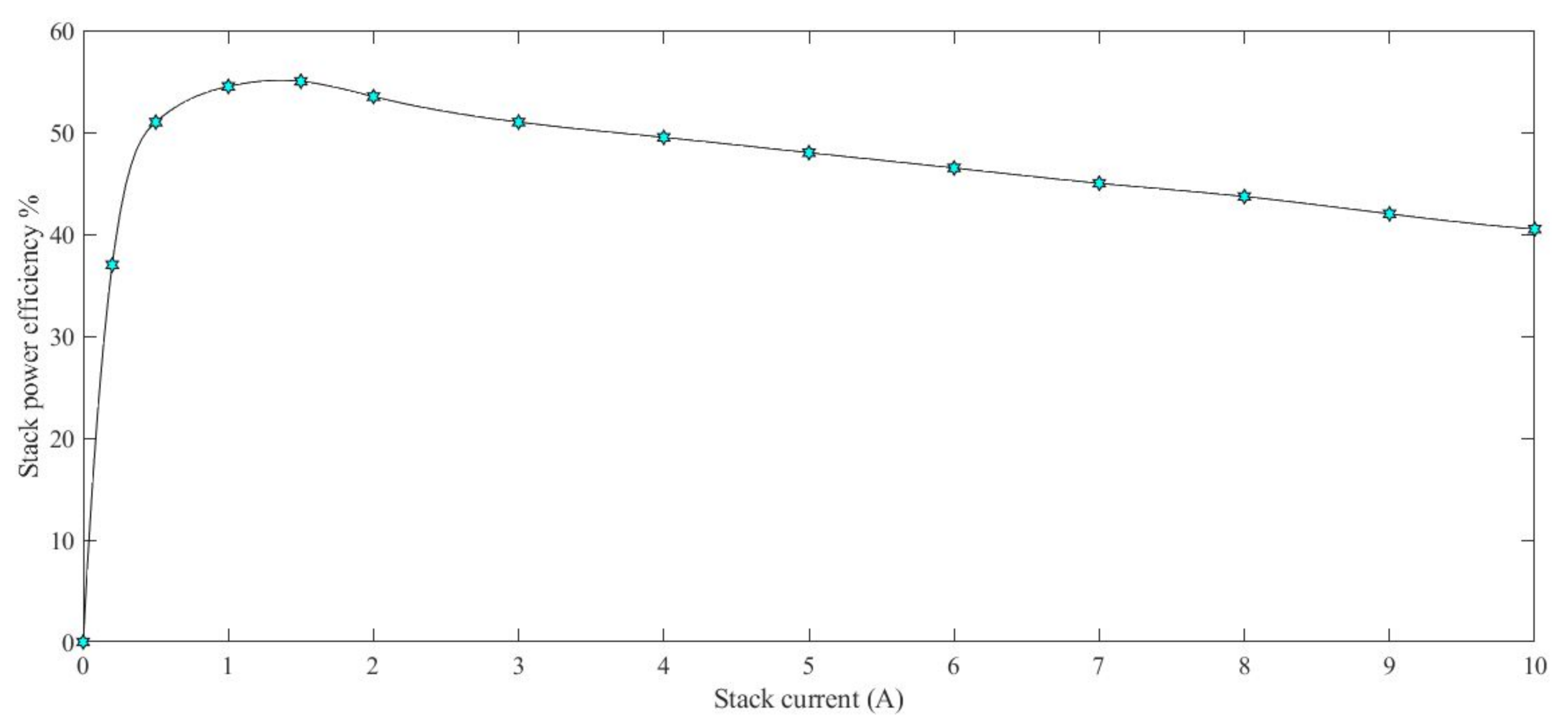
2.1. Polymer Electrolyte Membrane Fuel Cell

According to [23], the electrical energy generated by the PEMFC can be expressed as Equation (1). This is derived from a thermo-dynamical analysis of the device which takes into account the temperature and fuels partial pressures. Therefore, the looses are not considered in this theoretical expression.
E = 1.229 0.85 · 10 3 ( T 298 ) + 4.3 · 10 5 · T · [ l n ( P H 2 ) + 1 2 l n ( P O 2 ) ]
where T (K) is the stack temperature; P H 2 (atm) and P O 2 (atm) are, respectively, the partial pressure of H2 and O2. In order to make a realistic expression derived from Equation (1), three main electric losses which could be classified as activation ( e a c t ), ohmic ( e o h m ) and concentration ( e c o n ) losses, are added to the Equation (1). Hence, a realistic PEMFC output voltage is expressed as Equation (2) [24,25].
V c e l l = E e a c t e o h m e c o n
where e a c t , e o h m and e c o n , are respectively, given in Equation (3) [24,25,26,27].
e a c t = σ 1 + σ 2 · T + σ 3 · T · l n ( C O 2 ) + σ 4 · T · l n ( I ) e o h m = I · ( R m e m + R c o n ) e c o n = ψ · l n 1 J J m a x
The parameters σ 1 , σ 2 , σ 3 and σ 4 are parametric coefficients determined by the constructor, I is the current of the PEMFC, C O 2 is the oxygen concentration in the catalysts (mol · cm 3 ), ψ is a constant parameter, J is the current density, J m a x is the maximum current density, R m e m is the internal resistance of the electrolyte membrane, and R c o n is the resistance occurred due to the contact between the bipolar plates and the carbon electrodes.
The power generated by the PEMFC stack can be calculated using Equation (4); where N c e l l represents the number of cells used in the stack [25].
P s t a c k = V c e l l · I · N c e l l
The efficiency of the PEMFC is determined as the ratio of the electric power provided by the stack P s t a c k (W) to the one provided by the stack input P i n . This latter can be written as Equation (5); where, L H V is the hydrogen lower heating value (J/kg), and m ˙ H 2 is the hydrogen mass flow rate (kg/s).
P i n = L H V · m ˙ H 2
Therefore, using Equation (4) and (5), the efficiency of the PEMFC can expressed as Equation (6) [28,29]. This equation was used with experimental data in order to plot the efficiency which process is explained in further sections.
η s t a c k = P s t a c k P i n = V c e l l · I · N c e l l L H V · m ˙ H 2

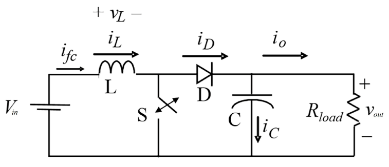
2.2. DC-DC Boost Converter

A DC-DC boost converter is a switch-mode power supply which converts a direct voltage coming from a DC source into another higher direct voltage value by adjusting the switch duty cycle d. The output voltage of the DC-DC boost converter can be calculated as Equation (7) [30,31].
V o u t = 1 1 d · V i n
As shown in Figure 2, a boost converter is consisted of an inductance, a metal oxide semiconductor field-effect transistor (MOSFET) switch, a Schottky diode, a capacitor, and a load resistance. The DC-DC converter operates in two modes, continuous conduction mode (CCM) and discontinuous conduction mode (DCM), depending on its storage capacity and the switching period T [32,33].
By assuming that the boost converter operates in the CCM, and by applying the Kirchhoff’s laws to the circuit, the averaged state-space representation can be determined as Equation (8) [34,35]
d i L d t d V o u t d t = 0 ( 1 d ) L ( 1 d ) C 1 R C . i L V o u t + 1 L 0 V i n y = 0 1 . i L V o u t

2.3. Control Design

In this section, a proportional-integral (PI) and an integral fast terminal sliding mode control (IFTSMC) are designed to stabilize and remain the PEMFC operating at an efficient and adequate power point.

2.3.1. PI Control

PI controller is widely used in most power electronic closed-loop systems. It is the most straightforward classical control which uses a feedback loop to generate an error e r . More specifically, the controller must track a set-point or a reference by adjusting the appropriate signal that supplied to the system. Hence, the controller uses the reference and the feedback, which is a measurement acquired by a sensor, to generate the control signal. The overall control function u of the PI controller is given in Equation (10) [36,37,38]; where e r is the error between the PEMFC current i L and the reference current i r e f (expressed in Equation (9)). K p and K i represents, respectively, the proportional and the integral coefficients.
e r = i L i r e f
u = K p e r + K i 0 t e r d t
The major drawback of the PI controller appears in determining its proportional and integral gain coefficients that correspond, respectively, with K P and K i . Besides, its vulnerability, due to the load variations, could be a major problem. However, in order to decrease the complexity of selecting the gain coefficients, the Ziegler-Nichols tuning method was used since it is an efficient trial and error method.

2.3.2. Integral Fast Terminal Sliding Mode Control (IFTSMC)

IFTSMC is a new type of terminal sliding mode control which was invented by the scientist Venkataraman and Gulati [39] in the Jet Propulsion Laboratory. It is a nonlinear and a robust control based on the concept of the conventional TSMC and through a development of SMC. The command law u of the IFTSMC consists of two terms, a discontinuous term u s w that remains the system on the sliding surface, and an equivalent term u e q that brings the system to the sliding surface [40]. The total command law can be expressed as Equation (11).
u = u e q + u s w
The discontinuous term u s w is defined in Equation (12); where, where k is a positive constant and sign(s) is the signum function [41].
u s w = L V o u t · k · s i g n ( s )
The equivalent term u e q is obtained by setting a sliding surface s and is finally achieved by establishing s ˙ = 0 [40]. The sliding surface given in Equation (13) is proposed; where the parameters α , λ , p and q are constants that satisfy the following condition: α > 0, λ > 0, p > 0, q > 0, 1 < p / q < 2 [42,43,44].
s = e r + α 0 t e r . d t + λ 0 t e r . d t p / q
The time derivative of the surface can be expressed as in Equation (14).
s ˙ = e r ˙ + α · e r λ p q · e r · 0 t e r . d t p q q
Also, the error expression was already defined in the Equation (9). As the reference current is constant, therefore, a derivative expression can be obtained from (8) which results in the following Equation (15).
e ˙ r = ( 1 d ) L i L + 1 L · V i n
Thus, through a combination of Equation (14), with the latter Equation (15), a complete expression of the surface derivative is gathered in the following Equation (16).
s ˙ = 1 d L . V o u t + 1 L . V i n + α · e r + λ p q · e r · 0 t e r . d t p q q s ˙ = u L . V o u t 1 L . V o u t + α · e r + 1 L . V i n + λ p q · e r · 0 t e r . d t p q q
Finally, stating that that s ˙ = 0 , the equivalent term of the control law is achieved as in Equation (17).
u e q = 1 V i n V o u t α · e r · L V o u t λ . e r . L V o u t p q · 0 t e r . d t p q q
Previous remarks in terms of the chosen surface, provided certain limitations to take into account at the moment of the constants tuning. However, these have also been adjusted through the minimization of the integral of the absolute error (IAE) that belongs to the Equation (18). This aims to achieve a suitable performance by taking into account the error reduction in real time.
I A E = 0 t | e ( t ) | d t

2.3.3. IFTSMC Stability Proof

The previous obtained control law can be analyzed in terms of the Lyapunov theory of stability. This states that if there exist a positive definite function: R n R so that V (x) > 0, V (0) = 0, V ( ) = and V ˙ ( x ) < 0, ∀x≠ 0; therefore the dynamical system is asymptotically stable. Consequently, to prove the stability of the PEMFC system, a positive definite Lyapunov candidate function is chosen as the Equation (19).
V ( s ) = 1 2 s 2
Thus, the derivative of the latter expression is established in the next expression such that s ˙ from (16) is replaced as follows.
V ˙ ( s ) = s s ˙ = s u L . V o u t 1 L . V o u t + 1 L . V i n + α · e r + λ p q · e r · 0 t e r . d t p q q
The replacement of the control term u with the Equations (11), (12) and (17), yields to the following expression. Further mathematical development as follows, accomplishes with the Lyapunov stability proof since V ˙ ( s ) is concluded to be less or equal to zero.
V ˙ ( s ) = s ( u e q + u s w ) L . V o u t 1 L . V o u t + 1 L . V i n + α · e r + λ p q · e r · 0 t e r . d t p q q = s V o u t L 1 V i n V o u t α · e r · L V o u t λ . e r . L V o u t p q · 0 t e r . d t p q q L V o u t . k . s i g n ( s ) + s 1 L . V o u t + 1 L . V i n + α · e r + λ p q · e r · 0 t e r . d t p q q = k · s · s i g n ( s ) = k · | s | 0

2.4. Digital Filter Design

In order to reduce ripples and chattering phenomenon, a digital filter was designed in Matlab. The command filter(b,a,x) requires the numerator b and denominator a coefficients which represent a rational transfer function, whereas the data input is defined as x. Provided that a = 1 and b = 1 / N , the result is a moving-average expression that filters the high frequency signals along the the number of elements N to be filtered (this is also known as the filter order) expressed in Equation (22) [45].
y [ k ] = i = 1 N 1 N x [ k i ]
The implementation of previous expression has been done through a Finite Impulse Filter (FIR) block in Simulink. The filter order was defined along the research as it is explained in the following sections. The sampling frequency was chosen is 10 kHz since it fits with the hardware limitations and data acquired.

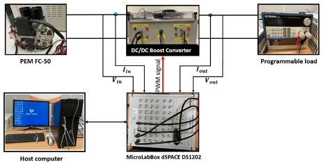
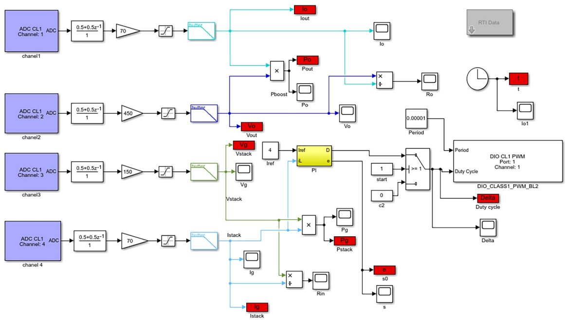
2.5. Description of the Test Bench

The experimental test bench, which is shown in Figure 3, was built at the laboratory of advanced control in the university of Vitoria-Gasteiz, Spain. It is consisted of a Heliocentric hy-Expert™ FC-50W and its auxiliaries, MicroLabBox dSPACE DS1202, step-up DC-DC power converter and programmable DC power.
Table 2 lists the technical specifications of the Heliocentric FC-50; where this latter consists of 10 cells stacked together to generate a rated power around 40 W.
The host computer has an INTEL processor type I7 7700k 4.5 GHz based on Kaby Lake architecture, and a powerful RAM of 32GB. It is used to design the controller and manage the system via the Matlab/Simulink™ environment software. The input and output signals are measured and observed via the ControlDesk software tools. The control algorithm has been implemented on a dSPACE DS1202 card to generate the pulse width modulation (PWM) signal, which activates the IGBT trigger of the boost converter. This latter was constructed by the research-group-TEP192 with the characteristics listed in Table 3.
The MicroLabBox dSPACE DS1202 is a powerful tool that used to linkage between the software (Simulink) and the hardware (the converter), via its real-time interface (RTI). It has the ability to receive and send the information among the converter, the Matlab/Simulink™ and ControlDesk software, as well as monitoring the signals of the real processes throughout the operation. It contains two digital input/output PWM ports, two RS232, two CAN, as well as 48 input/output channels which make it adapted to many different functions and activities. Furthermore, it has a powerful CPU of 2GHz and a field-programmable gate array (FPGA) that allows the user to make tests even for speedy control loops. A block diagram of the integrated MicroLabBox with the PEMFC, the boost converter, the host computer as well as the programmable DC power is shown in Figure 4. The programmable DC power is manufactured by BK-PRECISION, type 8500B, and it is used as a variable load resistance in order to test the performance of the proposed control algorithm.
The design of the digital controller on the Simulink™ graphical interface as well as its connections with the RTI blocks are shown in Figure 5.

3. Results and Discussion

The current/voltage and current/power characteristics of the practical FC-50W for diverse temperatures, are presented in Figure 6. It is noticed that the performance of the FC-50W is enhanced by the increase of temperature from 20 C to 46 C which could be interpreted by the rise of the membrane conductivity, and by the improvement in the exchange of the current density which will results in diminishing the activation losses. Notwithstanding these improvements, at higher temperatures such as T > 46 C , the conductivity of the membrane starts to drop due to the lack of the relative humidity; which will result in a reduction in the performance of the PEMFC. It should be noted that the performance study of the FC-50W was limited due to the constraints in the oxygen and hydrogen partial pressures; these were narrowed since the rates are automatically controlled by an integrated control.
When studying the performance and the behaviour of the PEMFC, a contrast between the maximum operating power point and maximum efficiency operating point must be made. In Figure 7, the current/efficiency characteristics of the Heliocentric hy-Expert™ FC-50W are presented. This was obtained based on Equation (6) through a variation of the stack current and gathering the mass flow rate variation of the hydrogen which was given by the Heliocentris software. Therefore, the curve was possible to be achieved. According to this figure, it can be seen that the best efficiency is obtained at low load currents [1–2 A]. However, according to Figure 6, the optimum operating power point is obtained at a high current range [6–8 A]. Therefore, it is mandatory to choose between the optimum power or efficiency, and this could be selected depending on the required power for the specific application. In this work, the authors preferred to establish an efficient operating power point while providing an important amount of power. Thus, by designing a suitable controller that able to remain the FC-50W operating at I = 4 A, an efficiency of almost 50 % while producing a power of 25 W can be achieved.
To hold and keep the FC-50W operating at the selected reference current I r e f = 4 A, PID and IFTSMC controllers were proposed. Their coefficient parameters obtained through Ziegler-Nichols and m i n { I A E } are enlisted in Table 4.
In order to test and view the performance of the proposed controllers, variations in the load resistance are adjusted, respectively, from 20 Ω to 50 Ω at t = 20 s, and from 50 Ω to 20 Ω at t = 40 s. These load variations, the duty cycle signal for both PI and IFTSMC, as well as their generated errors, are presented in Figure 8. Despite the sharp variations of the load resistance, it is clearly shown that both of controllers succeeded to converge the error to zero value; which will guarantee as a result the stability of the system. Figure 8 also demonstrates the drawbacks of the PI controller in terms of the converging time; hence, it takes up to more than 12 s to reach the equilibrium point while the proposed IFTSMC algorithm takes only 0.45 s.
The electric outputs of the FC-50W stack, under the application of PI and IFTSMC, are presented in Figure 9; where the three graphs shows, respectively, the stack current, stack voltage and stack power. At t = 20 s, by applying load variation from 20 Ω to 50 Ω , the PI shows an undershoot of 2.006 A in current, an overshoot of 1.147 V in voltage, and an undershoot of 10.05 W in power; while the proposed IFTSMC shows an undershoot of 1.997 A in current, an overshoot of 1.107 V in voltage, and an undershoot of 9.99 W in power. On the other hand, at t = 40 s, by applying load variation from 50 Ω to 20 Ω , the PI shows an overshoot of 4.086 A in current, an undershoot of 2.014 V in voltage, and an overshoot of 9.17 W in power; while the proposed IFTSMC shows an overshoot of 4.141 A in current, an undershoot of 2.012 V in voltage, and an overshoot of 9.26 W in power. According to these results, it is clear that both of PI and IFTSMC have almost the same performance in term of overshoots and undershoots; where the IFTSMC has an improvement of 0.06 W over the PI when increasing the load resistance, while the PI has an improvement of 0.09 W over the IFTSMC when decreasing the load resistance. However, it is clearly shown that the feature of the proposed IFTSMC appears in its capability to converge the system to the reference value with high speed (response time = 0.45 s).
Figure 10 shows the output signals behaviour of the step-up DC-DC converter. According to this figure, gradual and smooth movements to the desired value are obtained. However, in spite of the chattering phenomenon which is caused by the proposed IFTSMC control during the steady state, its robustness to converge the system in a short times which will results in a high tracking accuracy, is an important advantage over the conventional PI.
According to Figure 9 and Figure 10, it is noticed that the chattering phenomenon, which is a normal behavior of sliding mode control, occurred in the steady state could represent an obstacle for the proposed IFTSMC control; therefore, to eliminate these ripples, a a digital filter that diminished the high frequency components along 400 points was applied to the duty cycle (command law). The filtered signals of the FC-50W stack are presented in Figure 11. This latter demonstrates that by applying a digital filter, a chattering reduction from 0.65 A, 0.33 V, 2.76 W (Figure 9) to 0.08 A, 0.03 V, 0.36 W (Figure 11), are respectively obtained. By means of power percentage, a chattering reduction up to 91 % is obtained which results in a soft and smooth signals.
According to these results, it is clearly seen that the IFTSMC with the application of the digital filter has succeeded to keep the FC-50W stack operating at the desired power point while providing high tracking performance. Hence, high convergence speed with chattering reduction up to more than 91 % are obtained using the proposed IFTSMC algorithm. Besides, soft and fast dynamic behavior while guaranteeing the system stability are also obtained.

4. Conclusions

A Heliocentric hy-Expert™ FC-50W feeding programmable DC power supplies via a controlled boost converter is studied in this work. The closed-loop system which includes the FC-50W and its auxiliaries, the converter, the host computer and the programmable DC power supplies are implemented and linked to the MicroLabBox dSPACE DS1202. The suggested IFTSMC control scheme is designed to keep the PEMFC power system operating at an appropriate and efficient power point as well as to pursuit the trajectory with high tracking performance. The stability proof of the proposed IFTSMC is demonstrated via Lyapunov analysis; where its chattering phenomenon is cancelled via the application of a digital filter.
The experimental characteristics of the FC-50W for diverse temperatures are investigated and it is concluded that the performance of the PEMFC is enhanced by the increase of temperature from 20 C to 46 C , while it is reduced for higher temperatures. On the other hand and based on the efficiency characteristics of the PEMFC, it is concluded that for the performance improvement, it is mandatory to to choose between the optimum power point or the optimum efficiency.
An experimental comparative study is investigated between the IFTSMC and the well-known PI controller so as to reveal the merits of the proposed technique. Results have indicated that despite the sharp variations of the load resistance, both of controllers succeeded to converge the error to zero value; where, gradual and smooth movements to the desired value with global system stability are obtained. Results also have indicated that both of PI and IFTSMC have almost the same performance in term of overshoots and undershoots; however, it is clearly proven that the feature of the proposed IFTSMC appears in its capability to converge the system to the reference value with high speed (response time = 0.45 s).
The experimental comparative study also has proven the effectiveness of the LFP application, hence, up to more than 91 % of the chattering phenomenon of the IFTSMC could be eliminated. Therefore, it is clearly proven that the IFTSMC with the application of the digital filter has succeeded to keep the FC-50W stack operating at the desired power point while providing high tracking performance such as high convergence speed with significant chattering reduction. Finally, the obtained results of this work are quite encouraging and they give prospects for further advanced research to enhance and improve the performance of the PEMFC.

Author Contributions

Conceptualization, M.Y.S. and M.D.; methodology, M.Y.S. and M.D.; software, M.Y.S. and M.D.; validation, M.Y.S., M.D.; formal analysis, M.Y.S. and M.D.; investigation, M.Y.S. and M.D.; resources, O.B.; data curation, M.Y.S. and M.D.; writing—original draft preparation, M.Y.S. and M.D.; writing—review and editing, M.Y.S., M.D., O.B., C.N., J.M.G.d.D.; visualization, M.Y.S. and M.D.; supervision, O.B., A.C.; project administration, O.B.; funding acquisition, O.B. All authors have read and agreed to the published version of the manuscript.

Funding

The authors wish to express their gratitude to the Basque Government through the project SMAR3NAK (ELKARTEK KK-2019/00051), to the Diputación Foral de Álava (DFA) through the project CONAVAUTIN 2 and to the UPV/EHU for supporting this work.

Institutional Review Board Statement

Not applicable.

Informed Consent Statement

Not applicable.

Data Availability Statement

Not applicable.

Acknowledgments

The authors would like to acknowledge the Algerian government and the UPV/EHU for supporting this work.

Conflicts of Interest

The authors declare no conflict of interest.

Abbreviations

The following abbreviations are used in this manuscript:
PEMFCpolymer electrolyte membrane fuel cell
PIproportional-integral
IFTSMCintegral fast terminal sliding mode control
PEMFCsproton exchange membrane fuel cells
PWMpulse width modulation
PIDproportional-integral derivative
FOPIDfractional-order proportional-integral-derivative
TZTPtwo-zero/three-pole
PID-SSAPID using slap swarm algorithm
IRAincremental resistance algorithm
GAOgrey antlion optimizer
GWMgrey wolf optimizer
MBAmine-blast algorithm
FLCfuzzy logic control
P&Operturb and observe
FLC-PSOfuzzy logic control based on particle swarm optimization
ANFISadaptive neuro-fuzzy inference system
SMCsliding mode control
HOSM-QChigh order sliding mode based on quasi-continuous algorithm
HOSM-TAhigh order sliding mode based on twisting algorithm
HOSM-STAhigh order sliding mode based on super-twisting algorithm
TSMCsterminal sliding mode controls
DTSMCdistributed terminal sliding mode controller
PFTCproportional finite-time control
PACCproportional asymptotic convergent contro
PIFTCproportional-integral finite-time contro
FTSMCfast terminal sliding mode control
ITSMCintegral terminal sliding mode control
CLFcontrol Lyapunov function
TDEtime delay estimation
LHVhydrogen lower heating value
MOSFETmetal oxide semiconductor field effect transistor
CCMcontinuous-conduction-mode
DCMdiscontinuous-conduction-mode
TSMCterminal sliding mode
DACdigital to analog converter
ADCanalog to digital converter

References

  1. Anderson, T.R.; Hawkins, E.; Jones, P.D. CO2, the greenhouse effect and global warming: From the pioneering work of Arrhenius and Callendar to today’s Earth System Models. Endeavour 2016, 40, 178–187. [Google Scholar] [CrossRef] [Green Version]
  2. Kaberger, T. Progress of renewable electricity replacing fossil fuels. Glob. Energy Interconnect. 2018, 1, 48–52. [Google Scholar]
  3. Reddy, B.M.; Samuel, P. Modeling and Simulation of Proton Exchange Membrane Fuel Cell Hybrid Electric Vehicle; Springer: Berlin/Heidelberg, Germany, 2020; pp. 281–291. [Google Scholar]
  4. Delgado, S.; Lagarteira, T.; Mendes, A. Air Bleeding Strategies to Increase the Efficiency of Proton Exchange Membrane Fuel Cell Stationary Applications Fuelled with CO ppm-levels. Int. J. Electrochem. Sci. 2020, 15, 613–627. [Google Scholar] [CrossRef]
  5. Mardle, P.; Ji, X.; Wu, J.; Guan, S.; Dong, H.; Du, S. Thin film electrodes from Pt nanorods supported on aligned N-CNTs for proton exchange membrane fuel cells. Appl. Catal. B Environ. 2020, 260, 118031. [Google Scholar] [CrossRef]
  6. García-Olivares, A.; Solé, J.; Samsó, R.; Ballabrera-Poy, J. Sustainable European transport system in a 100% renewable economy. Sustainability 2020, 12, 5091. [Google Scholar] [CrossRef]
  7. Lee, D.; Lin, K.C. How to Transform Sustainable Energy Technology into a Unicorn Start-Up: Technology Review and Case Study. Sustainability 2020, 12, 3018. [Google Scholar] [CrossRef] [Green Version]
  8. Rastayesh, S.; Bahrebar, S.; Blaabjerg, F.; Zhou, D.; Wang, H.; Dalsgaard Sørensen, J. A System Engineering Approach Using FMEA and Bayesian Network for Risk Analysis—A Case Study. Sustainability 2020, 12, 77. [Google Scholar] [CrossRef] [Green Version]
  9. Friedrich, K.A.; Kallo, J.; Schirmer, J.; Schmitthals, G. Fuel cell systems for aircraft application. ECS Trans. 2009, 25, 193. [Google Scholar] [CrossRef]
  10. Akinyele, D.; Olabode, E.; Amole, A. Review of Fuel Cell Technologies and Applications for Sustainable Microgrid Systems. Inventions 2020, 5, 42. [Google Scholar] [CrossRef]
  11. Kester, W.; Erisman, B.; Thandi, G. Section 4 Switched Capacitor Voltage Converters. Switched Capacitor Voltage Converters. Available online: https://www.analog.com/media/en/training-seminars/design-handbooks/Practical-Design-Techniques-Power-Thermal/Section4.pdf (accessed on 14 November 2020).
  12. Belhaj, F.Z.; El Fadil, H.; Idrissi, Z.E.; Koundi, M.; Gaouzi, K. Modeling, Analysis and Experimental Validation of the Fuel Cell Association with DC-DC Power Converters with Robust and Anti-Windup PID Controller Design. Electronics 2020, 9, 1889. [Google Scholar] [CrossRef]
  13. Derbeli, M.; Sbita, L.; Farhat, M.; Barambones, O. Proton exchange membrane fuel cell—A smart drive algorithm. In Proceedings of the 2017 International Conference on Green Energy Conversion Systems (GECS), Hammamet, Tunisia, 23–25 March 2017; pp. 1–5. [Google Scholar]
  14. Derbeli, M.; Barambones, O.; Sbita, L. A Robust Maximum Power Point Tracking Control Method for a PEM Fuel Cell Power System. Appl. Sci. 2018, 8, 2449. [Google Scholar] [CrossRef] [Green Version]
  15. Derbeli, M.; Barambones, O.; Farhat, M.; Sbita, L. Efficiency Boosting for Proton Exchange Membrane Fuel Cell Power System Using New MPPT Method. In Proceedings of the 10th International Renewable Energy Congress (IREC), Sousse, Tunisia, 26–28 March 2019; pp. 1–4. [Google Scholar]
  16. Derbeli, M.; Farhat, M.; Barambones, O.; Sbita, L. Control of PEM fuel cell power system using sliding mode and super-twisting algorithms. Int. J. Hydrog. Energy 2017, 12, 8833–8844. [Google Scholar] [CrossRef]
  17. Silaa, M.Y.; Derbeli, M.; Barambones, O.; Cheknane, A. Design and Implementation of High Order Sliding Mode Control for PEMFC Power System. Energies 2020, 13, 4317. [Google Scholar] [CrossRef]
  18. Derbeli, M.; Barambones, O.; Farhat, M.; Ramos-Hernanz, J.A.; Sbita, L. Robust high order sliding mode control for performance improvement of PEM fuel cell power systems. Int. J. Hydrog. Energy 2020, 45, 29222–29234. [Google Scholar] [CrossRef]
  19. Derbeli, M.; Barambones, O.; Ramos-Hernanz, J.A.; Sbita, L. Real-time implementation of a super twisting algorithm for PEM fuel cell power system. Energies 2019, 12, 1594. [Google Scholar] [CrossRef] [Green Version]
  20. Shotorbani, A.M.; Ghassem-Zadeh, S.; Mohammadi-Ivatloo, B.; Hosseini, S.H. A distributed secondary scheme with terminal sliding mode controller for energy storages in an islanded microgrid. Int. J. Electr. Power Energy Syst. 2017, 93, 352–364. [Google Scholar] [CrossRef]
  21. Gudey, S.K.; Gupta, R. Recursive fast terminal sliding mode control in voltage source inverter for a low-voltage microgrid system. IET Gener. Transm. Distrib. 2016, 10, 1536–1543. [Google Scholar] [CrossRef]
  22. Armghan, H.; Yang, M.; Armghan, A.; Ali, N.; Wang, M.Q.; Ahmad, I. Design of integral terminal sliding mode controller for the hybrid AC/DC microgrids involving renewables and energy storage systems. Int. J. Electr. Power Energy Syst. 2020, 119, 105857. [Google Scholar] [CrossRef]
  23. Derbeli, M.; Farhat, M.; Barambones, O.; Sbita, L. Control of proton exchange membrane fuel cell (pemfc) power system using pi controller. In Proceedings of the International Conference on Green Energy Conversion Systems (GECS), Hammamet, Tunisia, 23–25 March 2017; pp. 1–5. [Google Scholar]
  24. Cruz Rojas, A.; Lopez Lopez, G.; Gomez-Aguilar, J.F.; Alvarado, V.M.; Sandoval Torres, C.L. Control of the air supply subsystem in a PEMFC with balance of plant simulation. Sustainability 2017, 9, 73. [Google Scholar] [CrossRef] [Green Version]
  25. Rezk, H.; Fathy, A. Performance improvement of PEM fuel cell using variable step-size incremental resistance MPPT technique. Sustainability 2020, 12, 5601. [Google Scholar] [CrossRef]
  26. Wan, Z.; Chang, H.; Shu, S.; Wang, Y.; Tang, H. A review on cold start of proton exchange membrane fuel cells. Energies 2014, 7, 3179–3203. [Google Scholar] [CrossRef] [Green Version]
  27. Louzazni, M.; Al-Dahidi, S.; Mussetta, M. Fuel Cell Characteristic Curve Approximation Using the Bézier Curve Technique. Sustainability 2020, 12, 8127. [Google Scholar] [CrossRef]
  28. Seyed Mahmoudi, S.M.; Sarabchi, N.; Yari, M.; Rosen, M.A. Exergy and exergoeconomic analyses of a combined power producing system including a proton exchange membrane fuel cell and an organic rankine cycle. Sustainability 2019, 11, 3264. [Google Scholar] [CrossRef] [Green Version]
  29. Wilberforce, T.; Olabi, A.G. Design of Experiment (DOE) Analysis of 5-Cell Stack Fuel Cell Using Three Bipolar Plate Geometry Designs. Sustainability 2020, 12, 4488. [Google Scholar] [CrossRef]
  30. Khatib, T.; Elmenreich, W.; Mohamed, A. Simplified iv characteristic tester for photovoltaic modules using a dc-dc boost converter. Sustainability 2017, 9, 657. [Google Scholar] [CrossRef] [Green Version]
  31. Derbeli, M.; Barambones, O.; Silaa, M.Y.; Napole, C. Real-Time Implementation of a New MPPT Control Method for a DC-DC Boost Converter Used in a PEM Fuel Cell Power System. Actuators 2020, 9, 105. [Google Scholar] [CrossRef]
  32. Erickson, R.W.; Maksimovic, D. Fundamentals of Power Electronics; Springer Science: Berlin/Heidelberg, Germany, 2007. [Google Scholar]
  33. Sarikhani, A.; Allahverdinejad, B.; Hamzeh, M.; Afjei, E. A continuous input and output current quadratic buck-boost converter with positive output voltage for photovoltaic applications. Sol. Energy 2019, 188, 19–27. [Google Scholar] [CrossRef]
  34. Derbeli, M.; Mrad, I.; Sbita, L.; Barambones, O. PEM fuel cell efficiency boosting—Robust MPP tracking. In Proceedings of the 9th International Renewable Energy Congress (IREC), Hammamet, Tunisia, 20–22 March 2018; pp. 1–5. [Google Scholar]
  35. Derbeli, M.; Charaabi, A.; Barambones, O.; Sbita, L. Optimal Energy Control of a PEM Fuel Cell/Battery Storage System. In Proceedings of the 10th International Renewable Energy Congress (IREC), Sousse, Tunisia, 26–28 March 2019; pp. 1–5. [Google Scholar]
  36. Chavero-Navarrete, E.; Trejo-Perea, M.; Jáuregui-Correa, J.C.; Carrillo-Serrano, R.V.; Rios-Moreno, J.G. Pitch Angle Optimization by Intelligent Adjusting the Gains of a PI Controller for Small Wind Turbines in Areas with Drastic Wind Speed Changes. Sustainability 2019, 11, 6670. [Google Scholar] [CrossRef] [Green Version]
  37. Aguilar-Mejía, O.; Minor-Popocatl, H.; Tapia-Olvera, R. Comparison and Ranking of Metaheuristic Techniques for Optimization of PI Controllers in a Machine Drive System. Appl. Sci. 2020, 10, 6592. [Google Scholar] [CrossRef]
  38. Arfaoui, J.; Rezk, H.; Al-Dhaifallah, M.; Ibrahim, M.N.; Abdelkader, M. Simulation-Based Coyote Optimization Algorithm to Determine Gains of PI Controller for Enhancing the Performance of Solar PV Water-Pumping System. Energies 2020, 13, 4473. [Google Scholar] [CrossRef]
  39. Venkataraman, S.T.; Gulati, S. Control of nonlinear systems using terminal sliding modes. Appl. Sci. 1993, 115, 554–560. [Google Scholar] [CrossRef]
  40. Slotine, J.J.E.; Li, W. Applied Nonlinear ControlPrentice Hall: Englewood Cliffs, NJ, USA; 1991Volume 199, p. 106354.
  41. Utkin, V.; Jürgen, G.; Ma, S. Sliding Mode Control in Electro-Mechanical Systems; CRC Press: Boca Raton, FL, USA, 1999; Volume 34. [Google Scholar]
  42. Rizi, M.T.; Eliasi, H. Nonsingular terminal sliding mode controller for voltage and current control of an islanded microgrid. Electr. Power Syst. Res. 2020, 185, 106354. [Google Scholar] [CrossRef]
  43. Feng, Y.; Yu, X.; Man, Z. Non-singular terminal sliding mode control of rigid manipulators. Automatica 2002, 38, 2159–2167. [Google Scholar] [CrossRef]
  44. Yu, X.; Man, Z. Fast terminal sliding-mode control design for nonlinear dynamical systems. IEEE Trans. Circuits Syst. I Fundam. Theory Appl. 2002, 49, 261–264. [Google Scholar]
  45. Zhao, H.; Zhang, L.; Liu, J.; Zhang, C.; Cai, J.; Shen, L. Design of a Low-Order FIR Filter for a High-Frequency Square-Wave Voltage Injection Method of the PMLSM Used in Maglev Train. Electronics 2020, 9, 729. [Google Scholar] [CrossRef]
Figure 1. Closed loop system.
Sustainability 13 02360 g001
Figure 2. DC-DC boost converter.
Sustainability 13 02360 g002
Figure 3. Overview of the experimental test bench.
Sustainability 13 02360 g003
Figure 4. System implementation.
Sustainability 13 02360 g004
Figure 5. Real−time control structure.
Sustainability 13 02360 g005
Figure 6. I/V and I/P characteristics of the FC-50W for diverse operating temperatures.
Sustainability 13 02360 g006
Figure 7. FC-50W current/efficiency characteristics.
Sustainability 13 02360 g007
Figure 8. (a): Load variations; (b): Duty cycle signal; (c): Error.
Sustainability 13 02360 g008
Figure 9. (a): Stack current; (b): Stack voltage; (c): Stack power.
Sustainability 13 02360 g009
Figure 10. (a): Boost converter output current; (b): Boost converter output voltage; (c): Boost converter output power.
Sustainability 13 02360 g010
Figure 11. (a): Filtered stack current; (b): Filtered stack voltage; (c): Filtered stack power.
Sustainability 13 02360 g011
Table 1. Summary of the recent reported approaches used for PEMFC power system.
ReferenceYearControllerConverterFeaturesDrawbacks
Ref. [12]2020PIDDC/DC buck and boost converters- Easy to implement.
- Low computational requirements.
- The most common used in the industry.
- Sensitive when facing large load variation.
- Inappropriate gains leads to the instability of the system.
- Tuning the controller parameters is difficult.
Ref. [13]2017FLCDC/DC boost converter- Easy to understand.
- It simplifies implementation.
- Similar to human reasoning.
- Simple to extend by adding new rules.
- Human expertise is required to achieve a suitable accuracy
- The system states have to be known.
- It is not always accurate since the results are perceived as a guess.
- Stability is not guaranteed.
Ref. [14]2018BSTPDC/DC boost converter- Popular technique for high order systems.
- Guaranteed stability design through Lyapunov function.
- Uncertainties could be handled to a certain level.
- Complex Lyapunov function. - High design complexity
- The exact mathematical model of the system is required
- Sensitive to parameter variation.
- Necessity of measuring all the state variables.
Ref. [15]2019SMCDC/DC boost converter- Simple structure.
- Easy parameter tuning.
- Applicable for a wide range of nonlinear systems.
- Robust to uncertainties and disturbances.
- Stability is guaranteed.
- Excessive chattering effect.
- Unguaranteed finite time convergence.
- The trajectories are not robust against perturbations during the reaching phase.
Ref. [17] Ref. [18] Ref. [19]2020 2020 2019QC TA STADC/DC boost converter- Chattering reduction in comparison with SMC.
- Finite time convergence.
- Robust to parameter uncertainties and disturbances.
- Complex design.
- Unable to use for first-order systems.
- Precise and accurate response is not guaranteed.
- Complex stability demonstration.
Ref. [20]2017DTSMCVoltage source converter- Finite time convergence.
- Capable of reducing the chattering.
- Robust to parameter uncertainties and disturbances.
- Slow convergence speed.
- Requires the knowledge of the system boundary uncertainties.
- Convergence problem may occur in case if the system states move away from the equilibrium.
- Problem of intrinsic singularity.
Ref. [21]2016FTSMCDC/AC inverter- Finite time convergence.
- Fast convergence rate.
- Capable of reducing the chattering.
- Robust to uncertainties and disturbances.
- Problem of intrinsic singularity.
- Can not be applied to higher order systems.
- The boundary information of system uncertainties is usually required to be known in advance.
- Problem of intrinsic singularity.
Ref. [22]2020ITSMCAC/DC inverter- Finite time convergence.
- High tracking accuracy.
- Robust to parameter uncertainties and disturbances.
- Applicable to high order systems.
- Slow convergence rate.
- Requires the knowledge of the system boundary uncertainties.
- Problem of intrinsic singularity.
Table 2. PEM FC50 technical data.
FC50 Characteristics Electrical Characteristics
Type of cellProton exchange membraneOperating voltage2.5–9 V
Cooling systemVentilatorsOperating current0–10 A
Fuel typePure hydrogenRated. Output power40 Watt
Dimensions W × H × D120 mm × 103 mm × 135 mmMax. Output power50 Watt
Weight1150 gOpen-circuit voltage9.0 V
H 2 Flow meter H 2 Kit of 15 bar
Precision0.8% of the quantified valueInlet H 2 pressure1–15 bar
Range of measuring10–1000 sml/minOutlet H 2 pressure0.4–0.8 bar
Thermal H 2 Kit of 200 bar
Operating temperature+15– 50 C Inlet H 2 pressure200 bar
Max. Start temperature+ 45 C Outlet H 2 pressure1–15 bar
Fuel detector H 2 Detector
Recommended H 2 purity5 with 99.99 % Type of sensors H 2 4%
H 2 input pressure0.4–8 bar (5.8–11.6 psig)Measuring principle3 electrode sensor
H 2 consumptionMax. 700 sml/min (at 0   C , 1013 bar)Operating range0–4%
Table 3. Technical data of the boost converter.
ParameterValue
Inductance6 μH
Input capacitor1500 μF
Output capacitor3000 μF
Max. Switching frequency25,000 HZ
Max. Input voltage V i n m a x = 60 V
Max. Iput current I i n m a x = 30 A
Max. Output voltage V o u t m a x = 250 V
Max. Output current I o u t m a x = 30 A
Table 4. Controllers parameters gains.
IFTSMCPI
p = 1 K c r = 0.04
q = 3 P c r = 12.08
α = 0.1 K p = 0.02
λ = 0.1 K i = 10
k = 0.5
Publisher’s Note: MDPI stays neutral with regard to jurisdictional claims in published maps and institutional affiliations.

