
Predict the Influence of Environmental Vibration from High-Speed Railway on Over-Track Buildings

Institute of Environmental Processes, College of Environmental and Resource Sciences, Zhejiang University, Hangzhou 310058, China
*
Author to whom correspondence should be addressed.
Sustainability 2021, 13(6), 3218; https://0-doi-org.brum.beds.ac.uk/10.3390/su13063218
Submission received: 7 February 2021
/
Revised: 9 March 2021
/
Accepted: 10 March 2021
/
Published: 15 March 2021
(This article belongs to the Special Issue Sustainable Railway System)
Abstract
:The vibration caused by railways is an environmental constraint in the development of over-track buildings. To study the influence of environmental vibration from the high-speed railway on over-track buildings, a finite element model including track, soil, and buildings was set up. Based on the vertical vibration acceleration sampled on the rail, the equivalent line load acting on rails vertically was obtained by a simplified model. On the basis of verifying the simulation model by measurement results, the vertical vibration induced by high-speed railways in over-track buildings was studied quantitatively. Through introducing correction terms relating to the thickness and height of the over-track platform, the story number, and the structure of the over-track building, an existing model released by the railway industry of China was improved. Compared with the existing model only being suitable for predicting vertical vibration of the first floor, the improved model can predict vertical vibration of different floors.
1. Introduction
By 2020, China’s railway mileage in operation has reached 146,300 km, including 38,000 km of high-speed railways [1]. In this sense, developing over-track buildings in the region of the urban railway can utilize land resources economically and intensively, which can alleviate the contradiction of urban land resource scarcity. However, railway vibration can be transmitted to over-track buildings through tracks and soil layers and produce indoor vibration pollution. Therefore, vibration impact from the railway is an environmental constraint in the development of over-track buildings [2,3,4]. Many studies on railway vibration source strength and its environmental impact have been conducted. Train speed, track type, etc. are the main factors that affect railway vibration source strength [5]. The degradation of railway sleepers due to dynamic loading action will also influence railway vibration source strength [6]. In the field of railway vibration impact on the surrounding environment, many pieces of research have focused on predicting the vibration impact of railways on neighboring and over-track buildings.
It is worth mentioning that the existing models for predicting the railway vibration effects on neighboring buildings can be divided into two categories. One category is only suitable for predicting the influence of vibration on the first floor of neighboring buildings, the other category is suitable for predicting the influence of vibration on different floors.
China’s railway industry presented an empirical model (See Equations (1) and (2)) [7] for the prediction of railway vibration based on vibration data from high-speed railway acquired by field test in 2010. The model applies only to the prediction of environmental vibration impact from railways on the first floor of neighboring buildings.
where is the environmental vibration caused by railways;
is the vibration source strength; Ci is the vibration correction term of train i; n is the number of pass-by trains; , ,
, , , , ,
are the correction terms of speed, axle weight, line type, track type, bridge height, geology, distance, and building type, respectively. To predict the influence of railway vibration on the first floor of adjacent buildings, Silva et al. [8] proposed a multiple linear regression model whose parameters include train speed, track type, geological condition, building type, and the distance between building and track. Similarly, Colaco et al. [9] studied the entire propagation path from vibration source (vehicle and track) to the receiver (building) and established a 2.5D finite element prediction model concerning the track, soil, and buildings. The model is simple in calculation but it can only predict the vibration response at the first floor of neighboring buildings.
In order to predict the vibration effect caused by trains on different floors of buildings near the railway, Madshus et al. [10] proposed a semi-empirical prediction model predicting vibration propagation. This model includes many parameters, train type, train speed, line quality, embankment design, and the distance from track to a building, as well as foundation, building structure, and the story number of the building. The Federal Railroad Administration of the U.S. Department of Transportation [5] published an empirical model predicting the influence of railway vibration on different floors of buildings near the railway. In this model, many correction terms relating to train speed, type of track structure, propagation distance, geologic conditions, building foundation, and the number of the story were considered, but its prediction accuracy is low relatively [11]. Using springs and viscous dampers to simulate a soil body, Auersch [12] built a simplified soil-wall-floor model to predict environmental vibration at each floor of buildings near railway based on an empirical transfer function. In China, Wang et al. [13] took the Wuhan-Guangzhou high-speed railway (265 km/h) as a research object and established a 3D finite element model of train-track-foundation-building to analyze the vibration response at the different floors of buildings based on measured data.
However, these models above predicting the influence of railway vibration on buildings near railway are not suitable for over-track buildings. In view of this point, Sanayei and other researchers [14,15] presented an impedance-based model to predict environmental vibration caused by trains and verified the reasonability of the model by analyzing the response of over-track buildings to railway vibration. Zheng et al. [16] established a finite element model of a multifunctional railway hub and analyzed the vibration impact of the Shanghai-Hangzhou high-speed railway passing the hub at the speed of 130 km/h on over-track buildings.
The vibration response at each floor of an over-track building increases with the rise of trains speed [17,18]. Accordingly, to reduce the investment of vibration pollution prevention in the development of over-track buildings in the region of urban railway, it is better that over-track buildings are constructed above railways with a low pass-by speed of trains. In this study, on the basis of the planning project of over-track buildings development in the region of high-speed railways with a pass-by speed of 105 km/h in Hangzhou, a finite element model was established. The reasonability of the model was verified by measurement results. Furthermore, this study quantitatively explored the influence of the thickness of the concrete floor of the over-track platform (as a transformation layer), the height of the over-track platform away from the ground, the structural type, and the number of stories of buildings on an over-track platform on indoor environmental vibration. Finally, a model predicting the vibration impact from railways on each floor of over-track buildings was proposed by improving an existing model released by the railway industry of China. Compared with the existing model only being suitable for predicting environmental vibration on the first floor of buildings, the improved model can predict the vertical maximum Z-weighted vibration acceleration level at different floors of over-track buildings. Research results can provide a theoretical and technical basis for the prediction and prevention of environmental vibration effects from the railway on over-track buildings.
2. A Simulation of the Vertical Vibration Load from a Train
To obtain the vertical vibration line load (a force per meter acting on rails through the wheels of the train), the vertical vibration acceleration on rails were sampled during the passage of a high-speed train (CRH380) of 105 km/h in the region of the railway, where a project of over-track buildings is planned in Hangzhou. Furthermore, the vertical vibration line load induced by a train was calculated by using an equivalent load method based on a simplified model of the vertical vibration below.
2.1. A Simplified Model of Vertical Vibration of a Train
Two bogies are located at the front and rear of each carriage of a high-speed train, respectively. Each bogie has two wheelsets. The mass of a train body distributes symmetrically from front to back and from left to right, and its center of gravity is located at the central axis. According to the symmetry, it is reasonable to select one wheelset for analysis. As shown in Figure 1, a simplified model of a train with a single degree of freedom is composed of mass, spring, and damping elements. In Figure 1, m1 is the mass of one wheelset; m2 is a quarter of the total mass of a carriage and its accessory; z1 and z2 are the vertical vibration displacements of the wheelset and the carriage, respectively; k and c are the suspension stiffness and the suspension damping, respectively. Specifically, the parameters of the train CRH380 are set below. m1 = 2000 kg, m2 = 9500 kg, k = 2,352,000 N/m, and c = 196,000 N∙s/m.
2.2. Fourier Transformation of Vertical Vibration Acceleration of Rails
A time-domain signal, of the vertical vibration acceleration on a rail can be regarded as a smooth Gaussian process with a mean of zero. In this way, the discrete vibration acceleration signal in the time domain can be expressed as
where N is the number of sampling points; is the fundamental frequency (); ∆t is the sampling interval; and is the time of sampling points.
The expression of in Equation (3) can be used to calculate the vertical vibration load caused by a train.
2.3. Equivalent Load of Vertical Vibration of a Train
An equilibrium equation of vertical motion of a train is established as Equation (6) according to Figure 1.
If the relative displacement of a carriage and a wheelset, is the difference between and , the Equation (6) can be rewritten as
Under the circumstance of ignoring the vertical bounce between wheel and rail, the vertical vibration acceleration of wheelset, is equal to the vertical vibration acceleration of rail, . Thus, Equation (8) can be rewritten as
On the basis of Equation (8),
can be solved.
According to D’Alembert’s principle, the equivalent vertical vibration load acting on rails (a wheel-rail force), can be expressed as
The equivalent vertical vibration line load acting on rails can be calculated by Equation (10).
where n and L are the number of bogies per carriage and the length of each carriage, respectively.
The equivalent vertical vibration line load induced by the high-speed train (CRH380) of 105 km/h is shown in Figure 2.
3. An Finite Element Model and Its Verification of Reasonability
A finite element model (see Figure 3) being composed of track and soil was established on the basis of geological condition, track lines distribution, and parameters of trains in the urban area where a project of over-track buildings is planned. The relevant parameters in this model were set as follows. The distance between the center lines of railways is 5 m, the distance between two rails of a railway is 1.4 m, the sleeper spacing is 0.6 m and the width at the bottom of the track-bed is 4 m. According to the geological condition of the land, the soil was simplified into three layers including an artificial fill layer with a thickness of 5 m, a cohesive soil layer with a thickness of 25 m, and a mucky soil layer with a thickness of 15 m. In addition, as shown in Figure 3, several viscoelastic solid units with a thickness of 1 m were set as an artificial boundary at the bottom of three layers of soil and around the soil in the model. The material parameters of rail, sleeper, track-bed, and three layers of soil are shown in Table 1 [19,20,21].
The vertical vibration line load caused by the high-speed train of 105 km/h was acted on one railway track. The step of line load in the time domain is 0.002 s. Verification point 1 and point 2 were set on the sleepers of this railway track and its adjacent railway track, respectively (see Figure 4). The maximum vertical Z-weighted vibration acceleration level () at each verification point by simulation and measurement is shown in Table 2. It can be seen from Table 2 that the difference between the simulated and the measured at verification point 1 is 4.0 dB and the relative error is 3.54%. The difference at verification point 2 is 4.0 dB and the relative error is 4.50%. The relative error between the simulated and the measured at each verification point is less than 5%, which indicates that this simulation model is accurate relatively and the parameter setting in the model is reasonable.
4. A Single Factor Analysis of Environmental Vibration Influence on Over-Track Buildings
4.1. A Simulation Model and Its Parameters Setting
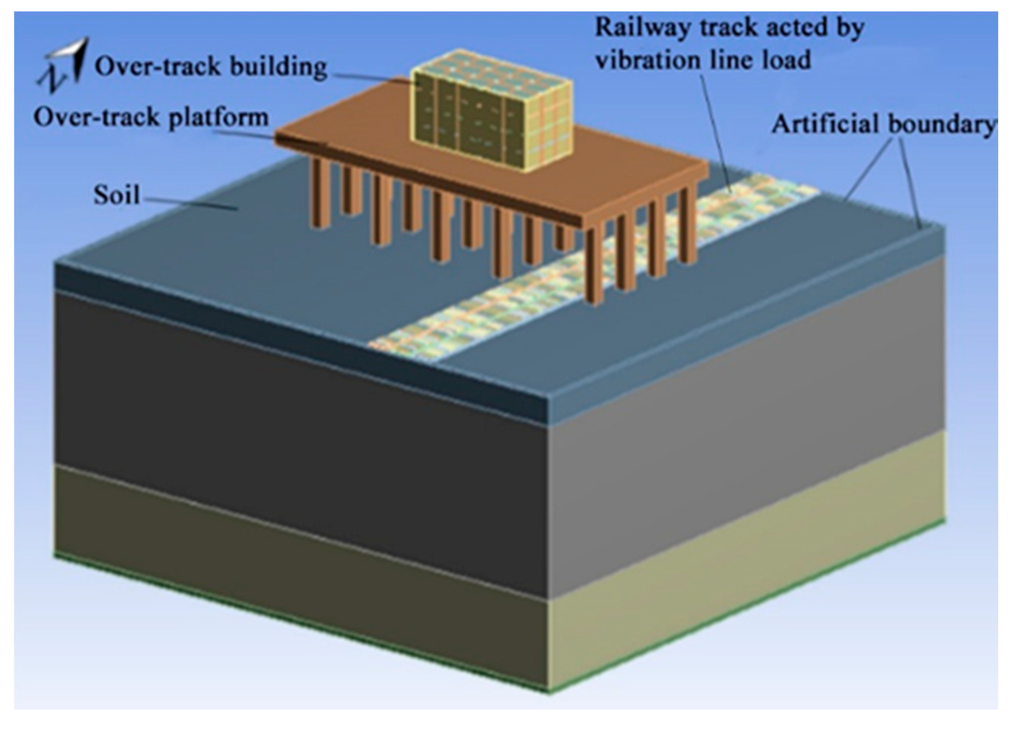
To study the vibration impact from railways on over-track buildings, a 3D finite element model (see Figure 5) composed of the track, soil, and an over-track building was established on the basis of the geometrical model in Figure 3. According to the design scheme of an over-track building project in Hangzhou, the parameters in the model were set as follows. The height of the over-track platform away from the ground is 16.3 m, the thickness of the concrete floor of the over-track platform is 2.5 m, the distance between the center of the over-track building and the centerline of the railway track is 16.5 m, the over-track building is a multi-story building with a frame structure, and the height of each story is 3 m. The vibration influence from railways on the over-track building was studied by changing a single factor shown in Table 3, such as the number of stories of the over-track building, the structural type of over-track building, the thickness of the over-track platform, and the height of the over-track platform away from the ground [22], etc.
4.2. An Analysis of Influence Factors on Environmental Vibration
4.2.1. The Influence of Building Structure Type and Total Storey Number
The central point at each floor of the over-track building was chosen as a prediction point in the simulation. The maximum vertical Z-weighted vibration acceleration levels () of prediction points at all floors and corresponding story numbers were logarithmically fitted. The fitting function is shown as
where n is the story number of the over-track building. As shown in Figure 6, the determination coefficients (R2) of fitting functions are all higher than 0.8. It can be seen from Figure 6 that the s at the center of different floors in frame buildings and shear wall buildings both increase with the increase of the story number. The s at the center of different floors in multi-story, sub-high-rise, and high-rise frame buildings are 79.3~84.3 dB, 81.3~86.8 dB, and 83.8~91.8 dB and the average increments of per unit floor are 1.25 dB, 0.55 dB, and 0.5 dB, respectively. The s at the center of different floors of three types of shear wall buildings are 79.2~79.9 dB, 81.3~83.0 dB, and 83.7~86.7 dB, and the average increments of per unit floor are 0.18 dB, 0.17 dB, and 0.19 dB, respectively. It indicates that the s at the center of different floors in three types of frame buildings are 0.1~4.4 dB, 0~3.8 dB, and 0.1~5.1 dB higher than that in three types of shear wall buildings, respectively.
In this study, the at the center of each floor of multi-story (four stories) and sub-high-rise (10 stories) frame buildings both increase with the rise of story, and the increments of per unit floor are 1.25 dB and 0.55 dB, respectively. Wang et al. [13] and Xia et al. [23] measured the at each floor of the three-story frame building and the six-story frame building near railways, respectively, and found that the s at different floors of two buildings increase with the rise of story and the increments of per unit floor are 1.35 dB and 0.85 dB, respectively. The results of the present study are similar to those of the study above.
4.2.2. The Influence of Over-Track Platform Thickness
When the thickness of the over-track platform (T) was set as 2 m, 2.5 m, and 3 m, respectively, the at the center of different floors of the frame buildings and corresponding story numbers were fitted logarithmically. The results are shown in Figure 7. It indicates that the s at the center of different floors in multi-story, su- high-rise, and high-rise frame buildings are 82.3~87.3 dB, 84.6~88.1 dB, and 84.9~91.9 dB, respectively when the T is 2 m. When the T is 2.5 m, the s at different floors of three types of buildings are 79.3~84.3 dB, 81.3~86.8 dB, and 83.8~91.8 dB, respectively. When the T is 3 m, the s at different floors of three types of buildings are 78.6~83.9 dB, 79.2~85.2 dB, and 80.4~90.0 dB, respectively. The results show that increasing the thickness of the over-track platform can reduce indoor environmental vibration from railways effectively. Furthermore, when the thickness of the over-track platform increases 0.5 m, the at the center of different floor of multi-storey, sub high-rise, and high-rise frame buildings will decrease 0.4~3.0 dB, 1.3~3.3 dB, and 0.1~3.4 dB, respectively. Similarly, the study from Sanayei et al. [14,15] shows the vibration transmitting to upper floors will decrease with the increase of the thickness of the ground floor, and the vibration of floors will decrease about 4~5.6 dB when the thickness of the ground floor increases 0.5 m.
4.2.3. The Influence of Over-Track Platform Height Away from Ground
When the height of the over-track platform away from the ground (H) set as 12.3 m, 16.3 m, and 20.3 m, respectively, the logarithmic fitting (See Figure 8) was performed between the at the center of the different floors of the frame buildings and corresponding story numbers. Results in Figure 8 indicate that the s at the center of different floors in multi-story, sub-high-rise, and high-rise frame buildings are 79.2~83.9 dB, 81.1~86.7 dB, and 83.1~91.2 dB, respectively when the H is 12.3 m. When the H is 16.3 m, the s at different floors of three types of buildings are 79.3~84.3 dB, 81.3~86.8 dB, and 83.8~91.8 dB, respectively. When the H is 20.3 m, the s at different floors of three types of buildings are 79.6~84.8 dB, 82.0~87.3 dB, and 84.5~92.3 dB, respectively. Obviously, s at the center of different floors will increase 0.1~0.5 dB, 0.1~0.9 dB, and 0.3~0.9 dB in multi-story, sub-high-rise, and high-rise frame buildings, respectively when the height of over-track platform away from ground increases 4 m.
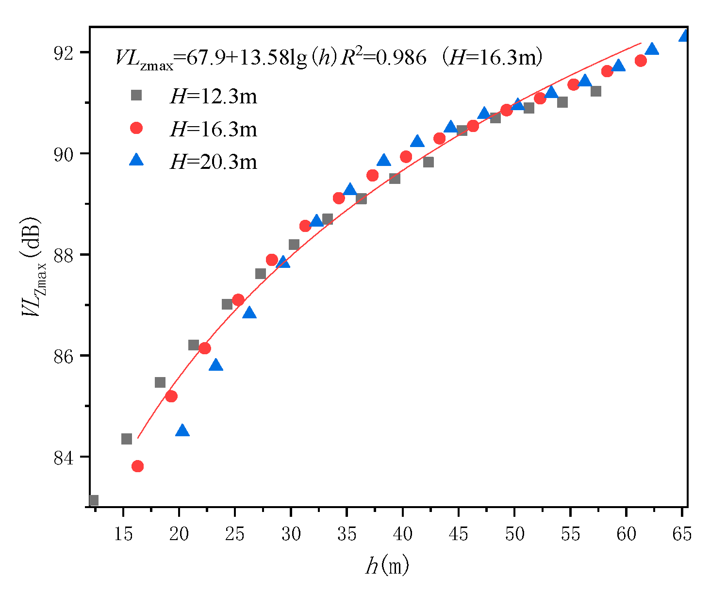
For the same story of buildings on the over-track platform, its actual height away from the ground increases with the increase of the height of the over-track platform away from the ground. If the absolute height of the story away from the ground in an over-track building, h is taken as a horizontal coordinate and the at the center of the floor is taken as a longitudinal coordinate, the logarithmic fitting as shown in Equation (11) was performed between h and (See Figure 9). It can be seen in Figure 9 that will increase with the increase of the absolute height (h) of story away from the ground when an over-track building is on the over-track platform with a different height H. The studies conducted by Wang et al. [13] and Xia et al. [24] also show that the environmental vibration impact induced by high-speed railways on buildings near railways increases with the increase of the height of the story away from the ground.
5. A Prediction Model of the Environment Vibration Impact from High-Speed Railway on Over-Track Buildings
A model predicting environmental vibration influence on the first floor of buildings adjacent to railways has been given by the Ministry of Railways of the People’s Republic of China (MRPRC) in 2010 [7] and the main calculation formulas in this model are given as Equation (1) and Equation (2) in the part of the Introduction. To establish a prediction model of vibration influence induced by railways on different floors of over-track buildings, the model above will be improved on the basis of simulation results in this study. Through introducing three correction terms, , and , which are relating to the thickness of the over-track platform and its height away from the ground, the story of the over-track building, and the structural type of the over-track building, respectively. The improved model is shown as
where is the maximum vertical Z-weighted vibration acceleration level at the center of the nth floor of the over-track building during the passage of a high-speed train, is the on the ground below over-track building, which can be calculated by Equations (1) and (2).
5.1. The Correction Term of the Thickness of Over-Track Platform and Its Height Away from Ground, CP
When the thickness of the over-track platform (T) and its height away from the ground (H) is different, the vibration influence induced by railways on the first floor of the over-track building will be different. Thus, to consider the influence of T and H on vibration prediction results, a correction term, is introduced to correct the predicted by the existing model of MRPRC. According to the simulation results given in Figure 7 and Figure 8, can be determined through Equation (13). In Equation (13), the values of several parameters are shown in Table 4. According to the correction term given in Equation (13), can be obtained on the basis of
where the constant term a is the difference between the and the when the T is 2.5 m and H is 16.3 m. and are the variance of of frame building when T and H increase one meter separately.
5.2. The Correction Term of Storey,
In order to predict the vibration influence on different stories of over-track buildings, it is necessary to introduce a correction term, relating to the story number. is the difference between the at the center of the nth floor () and the of the over-track building with a frame structure. It can be seen from Figure 6, Figure 7 and Figure 8 that the and the of a frame building can be expressed as and , respectively. can be calculated by Equation (14), in which the values of coefficient k are shown in Table 5.
5.3. The Correction Term of Building Structure,
The correction term relating to story, of frame buildings was given in Section 4.2. In order to predict the vibration response at each floor of a building with a shear wall structure, it is necessary to further introduce a correction term, of the building structure. is the difference between the at the center of the nth floor of a shear wall building and the at the center of the nth floor of a frame building. Figure 6 shows that the of a frame building and a shear wall building can be expressed as and , respectively. Thus, can be calculated by Equation (15), where the values of and are presented in Table 6.
6. Conclusions
To study the influence of environmental vibration from a high-speed railway on over-track buildings, a finite element model including track, soil, and buildings was set up. Based on the vertical vibration accelerations sampled on the rail, the equivalent line load acting on rails vertically is obtained by a simplified model. On the basis of the verification of the simulation model, the vertical vibration induced by high-speed railway in over-track buildings was studied quantitatively through a computer simulation. The main conclusions are as follows.
(1) The s at the center of different floors in frame buildings and shear wall buildings both increase with the increase of story number. The s at the center of different floors in multi-story, sub-high-rise, and high-rise frame buildings are 0.1~4.4 dB, 0~3.8 dB, and 0.1~5.1 dB higher than that in three types of shear wall buildings, respectively.
(2) Increasing the thickness of the over-track platform can reduce the indoor environmental vibration from railways effectively. When the thickness of the over-track platform increases 0.5 m, the at the center of different floor of multi-storey, sub high-rise, and high-rise frame buildings will decrease 0.4~3.0 dB, 1.3~3.3 dB, and 0.1~3.4 dB, respectively.
(3) The s at the center of different floors will increase 0.1~0.5 dB, 0.1~0.9 dB, and 0.3~0.9 dB in multi-story, sub-high-rise, and high-rise frame buildings, respectively, when the height of over-track platform away from ground increases 4 m.
(4) By introducing correction terms relating to the thickness of the over-track platform and its height away from the ground, the story of the over-track building and the structure of the over-track building, the existing model of railway vibration prediction released by the Ministry of Railways of the People’s Republic of China was improved. The improved model can predict the vertical maximum Z-weighted vibration acceleration level at different floors of over-track buildings.
Based on the model improved by this study, researchers can determine the amount of indoor environment vibration exceeding relative standards in over-track buildings. The corresponding prevention measures of environmental vibration effects from the railway on over-track buildings can be selected, which can provide a guideline for the design of over-track buildings.
Author Contributions
Conceptualization, G.D. and Z.X.; methodology, G.D.; software, G.D.; validation, Z.X. and J.G.; formal analysis, Z.X.; investigation, J.G.; resources, G.D.; data curation, Z.X.; writing—original draft preparation, G.D. and Z.X.; writing—review and editing, G.D. and Z.X.; visualization, J.G.; supervision, G.D.; project administration, G.D. All authors have read and agreed to the published version of the manuscript.
Funding
This research received no external funding.
Institutional Review Board Statement
Not applicable.
Informed Consent Statement
Not applicable.
Data Availability Statement
The study did not report any data.
Conflicts of Interest
The authors declare no conflict of interest.
References
- Zhang, J.; Zhang, J. Comprehensive Evaluation of Operating Speeds for High-Speed Railway: A Case Study of China High-Speed Railway. Math. Probl. Eng. 2021, 2021, 8826193. [Google Scholar]
- Nering, K.; Kowalska-Koczwara, A.; Stypuła, K. Annoyance Based Vibro-Acoustic Comfort Evaluation of as Summation of Stimuli Annoyance in the Context of Human Exposure to Noise and Vibration in Buildings. Sustainability 2020, 12, 9876. [Google Scholar] [CrossRef]
- Eizaguirre-Iribar, A.; Grijalba, O.; Hernández-Minguillón, R.J. An Integrated Approach to Transportation and Land-Use Planning for the Analysis of Former Railway Nodes in Sustainable Transport Development: The Case of the Vasco-Navarro Railway. Sustainability 2021, 13, 322. [Google Scholar] [CrossRef]
- Martínez Fernández, P.; Villalba Sanchís, I.; Botello Rojas, F.; Franco, R.I. Monitoring and analysis of vibration transmission for various track typologies. A case study. Transp. Res. Part D Transp. Environ. 2013, 24, 98–109. [Google Scholar] [CrossRef]
- U.S. Department of Transportation Federal Railroad Administration. High-Speed Ground Transportation Noise and Vibration Impact Assessment; U.S. Department of Transportation Federal Railroad Administration: Washington, DC, USA, 2005.
- Ferdous, W.; Manalo, A. Failures of mainline railway sleepers and suggested remedies—Review of current practice. Eng. Fail. Anal. 2014, 44, 17–35. [Google Scholar] [CrossRef]
- Ministry of Railways of the People’s Republic of China. Guidance on Noise and Vibration Source Values and Governance Principles for Environmental Impact Assessment of Railway Construction Projects (2010 Revision). Available online: https://www.sooooob.cn/information/2674.htm (accessed on 27 May 2010).
- Paneiro, G.; Durão, F.O.; de Silva, M.C.; Neves, P.F. Prediction of ground vibration amplitudes due to urban railway traffic using quantitative and qualitative field data. Transp. Res. Part D Transp. Environ. 2015, 40, 1–13. [Google Scholar] [CrossRef]
- Colaco, A.; Costa, P.A.; Amado-Mendes, P.; Godinho, L. Prediction of vibrations and reradiated noise due to railway traffic: A comprehensive hybrid model based on a finite element method and of fundamental solutions approach. J. Vib. Acoust. 2017, 139, 061009. [Google Scholar] [CrossRef]
- Madshus, C.; Bessason, B.; Rvik, L.H. Prediction model for low frequency vibration from high speed railways on soft ground. J. Sound Vib. 1996, 193, 195–203. [Google Scholar] [CrossRef]
- Verbraken, H.; Lombaert, G.; Degrande, G. Verification of an empirical prediction method for railway induced vibrations by means of numerical simulations. J. Sound Vib. 2011, 330, 1692–1703. [Google Scholar] [CrossRef]
- Auersch, L. Building response due to ground vibration-simple prediction model basedon experience with detailed models and measurements. Int. J. Acoust. Vib. 2010, 15, 101–112. [Google Scholar]
- Wang, X.Q.; Hu, Z.X.; Zhang, H.J. Analysis of vibration characteristics of adjacent buildings near the high speed railway of Wuhan to Guangzhou. Noise Vib. Control 2018, 38, 132–136. [Google Scholar]
- Sanayei, M.; Zhao, N.; Maurya, P.; Moore, J.A.; Zapfe, J.A.; Hines, E.M. Prediction and mitigation of building floor vibrations using a blocking floor. J. Struct. Eng. 2012, 138, 1181–1192. [Google Scholar] [CrossRef]
- Sanayei, M.; Anish, K.P.; Moore, J.A.; Brett, C.R. Measurement and prediction of train-induced vibrations in a full-scale building. Eng. Struct. 2014, 77, 119–128. [Google Scholar] [CrossRef]
- Zheng, X.D.; Geng, C.Z. Vibration effect simulation analysis of superstructure in Xinzhuang Hub project. J. Tongji Univ. Nat. Sci. 2014, 42, 1557–1561. [Google Scholar]
- Alabi, B. A parametric study on some aspects of ground-borne vibrations due to rail traffic. J. Sound Vib. 1992, 153, 77–87. [Google Scholar] [CrossRef]
- Sheng, X.; Jones, C.J.C.; Thompson, D.J. A theoretical study on the influence of the track on train-induced ground vibration. J. Sound Vib. 2004, 272, 909–936. [Google Scholar] [CrossRef]
- Zou, C. Train-Induced Vibration Transmission and Mitigation in Metro Depot and Over-Track Buildings; South China University of Technology: Guangzhou, China, 2017. [Google Scholar]
- Wu, C.F.; Zhu, X.R.; Liu, X.M. Studies on variability of shear strength indexes for several typical stratums in Hangzhou area. Chin. J. Geotech. Eng. 2005, 94–99. Available online: https://en.cnki.com.cn/Article_en/CJFDTotal-YTGC20050100F.htm (accessed on 14 March 2021).
- Ferdous, W.; Manalo, A.; AlAjarmeh, O.; Mohammed, A.A.; Salih, C.; Yu, P.; Mehrinejad Khotbehsara, M.; Schubel, P. Static behaviour of glass fibre reinforced novel composite sleepers for mainline railway track. Eng. Struct. 2021, 229, 111627. [Google Scholar] [CrossRef]
- GB 50352-2019. Uniform Standards for Civil Building Design; China Building Standard Design and Research Institute Co., Ltd.: Beijing, China, 2019. [Google Scholar]
- Xia, H.; Chen, J.G.; Wei, P.B.; Xia, C.; De Roeck, G.; Degrande, G. Experimental investigation of railway train-induced vibrations of surrounding ground and a nearby multi-story building. Earthq. Eng. Eng. Vib. 2009, 8, 137–148. [Google Scholar] [CrossRef]
- Xia, H.; Zhang, N.; Cao, Y.M. Experimental study of train-induced vibrations of environments and buildings. J. Sound Vib. 2005, 280, 1017–1029. [Google Scholar] [CrossRef]
Figure 1.
A simplified model of vertical vibration of a train.

Figure 2.
The line load of vertical vibration from the train.

Figure 3.
The geometrical model simulating railway track and soil.

Figure 4.
The locations of two verification points.

Figure 5.
The finite element model of track, soil, and over-track building.

Figure 6.
The at each floor of the frame structure or shear wall structure buildings.

Figure 7.
The at each floor with different thickness of over-track platform.

Figure 8.
The at the center of each floor of frame buildings on an over-track platform.

Figure 9.
The at each floor of frame building with different absolute heights away from the ground.


Table 1.
The material parameters of each component.
| Materials | Density (kg/m3) | Elastic Modulus (MPa) | Poisson’s Ratio |
|---|---|---|---|
| Rail | 7850 | 205,900 | 0.30 |
| Sleeper | 2400 | 30,000 | 0.20 |
| Track-bed | 1800 | 300 | 0.35 |
| Artificial fill layer | 1980 | 205 | 0.31 |
| Cohesive soil layer | 1940 | 175 | 0.44 |
| Mucky soil layer | 1530 | 120 | 0.35 |
Table 2.
A comparison between measured results and simulated results.
| Verification Point | ||||
|---|---|---|---|---|
| Measured Result | Simulated Result | Difference | Relative Error | |
| Point 1 | 113.0 | 109.0 | 4.0 | 3.54% |
| Point 2 | 88.9 | 92.9 | 4.0 | 4.50% |
Table 3.
The range of different influence factors in simulation.
| The Number of Storey of Over-Track Building | The Structural Type of Over-Track Building | The Thickness of Over-Track Platform (m) | The Height of Over-Track Platform Away from Ground (m) |
|---|---|---|---|
| Multi-layer (4 storeys), sub high-rise (10 storeys), high-rise (16 storeys) | Frame structure or shear wall structure | 2, 2.5, 3 | 12.3, 16.3, 20.3 |
Table 4.
The value of each coefficient in the correction term .
| Building Types | a (dB) | ||||
|---|---|---|---|---|---|
| T = 2.0~2.5 (m) | T = 2.5~3.0 (m) | H = 12.3~16.3 (m) | H = 16.3~20.3 (m) | ||
| Multi-storey | −2.5 | −6.0 | −1.4 | 0.025 | 0.075 |
| Sub high-rise | −0.5 | −6.6 | −4.2 | 0.05 | 0.15 |
| High-rise | 2.0 | −6.8 | −2.2 | 0.15 | 0.2 |
Table 5.
The values of coefficient k in the correction term .
| Building Types | K |
|---|---|
| Multi-story | 7.76~8.42 |
| Sub high-rise | 3.46~5.86 |
| High-rise | 6.09~8.44 |
Table 6.
The value of each coefficient in the correction term .
| Building Types | ||||
|---|---|---|---|---|
| Frame | Shear Wall | Frame | Shear Wall | |
| Multi-storey | 0 | −7.02 | 0 | −0.2 |
| Sub high-rise | 0 | −3.72 | 0 | −0.4 |
| High-rise | 0 | −4.44 | 0 | 0.3 |
Publisher’s Note: MDPI stays neutral with regard to jurisdictional claims in published maps and institutional affiliations. |
© 2021 by the authors. Licensee MDPI, Basel, Switzerland. This article is an open access article distributed under the terms and conditions of the Creative Commons Attribution (CC BY) license (http://creativecommons.org/licenses/by/4.0/).
Share and Cite
MDPI and ACS Style
Di, G.; Xie, Z.; Guo, J. Predict the Influence of Environmental Vibration from High-Speed Railway on Over-Track Buildings. Sustainability 2021, 13, 3218. https://0-doi-org.brum.beds.ac.uk/10.3390/su13063218
AMA Style
Di G, Xie Z, Guo J. Predict the Influence of Environmental Vibration from High-Speed Railway on Over-Track Buildings. Sustainability. 2021; 13(6):3218. https://0-doi-org.brum.beds.ac.uk/10.3390/su13063218
Chicago/Turabian StyleDi, Guoqing, Ziyin Xie, and Jingyi Guo. 2021. "Predict the Influence of Environmental Vibration from High-Speed Railway on Over-Track Buildings" Sustainability 13, no. 6: 3218. https://0-doi-org.brum.beds.ac.uk/10.3390/su13063218
Note that from the first issue of 2016, this journal uses article numbers instead of page numbers. See further details here.