
Thermo-Hydraulic Performance of U-Tube Borehole Heat Exchanger with Different Cross-Sections


1
School of Civil and Architecture Engineering, Jiangsu University of Science and Technology, Zhenjiang 212003, China
2
School of Architecture and Civil Engineering, Anhui University of Science and Technology, Huainan 232000, China
3
School of Civil Engineering, Shaoxing University, Shaoxing 312000, China
*
Authors to whom correspondence should be addressed.
Sustainability 2021, 13(6), 3255; https://0-doi-org.brum.beds.ac.uk/10.3390/su13063255
Submission received: 23 February 2021
/
Revised: 8 March 2021
/
Accepted: 12 March 2021
/
Published: 16 March 2021
(This article belongs to the Special Issue Energy and Water Integration System)
Abstract
:For reducing the initial GSHP investment, the heat transfer efficiency of the borehole heat exchange (BHE) system can be enhanced to reduce the number or depth of drilling. This paper proposes a novel and simple BHE design by changing the cross-sectional shape of the U-tube to increase the heat transfer efficiency of BHEs. Specifically, in this study, we (1) verified the reliability of the three-dimensional numerical model based on the thermal response test (TRT) and (2) compared the inlet and outlet temperatures of the different U-tubes at 48 h under the premise of constant leg distance and fluid area. Referent to the circular tube, the increases in the heat exchange efficiencies of the curved oval tube, flat oval tube, semicircle tube, and sector tube were 13.0%, 19.1%, 9.4%, and 14.8%, respectively. (3) The heat flux heterogeneity of the tubes on the inlet and outlet sides of the BHE, in decreasing order, is flat oval, semicircle, curved oval, sector, and circle shapes. (4) The temperature heterogeneity of the borehole wall in the BHE in decreasing order is circle, sector, curved oval, flat oval, and semicircle shapes. (5) Under the premise of maximum leg distance, referent to the heat resistance of the tube with a circle shape at 48 h, the heat exchange efficiency of the curved oval, flat oval, semicircle, and sector tubes increased 12.6%, 17.7%, 10.3%, and 7.8%, respectively. (6) We found that the adjustments of the leg distance and the tube shape affect the heat resistance by about 25% and 12%, respectively. (7) The flat-oval-shaped tube at the maximum leg distance was found to be the best tube design for BHEs.
1. Introduction
With increasing awareness of environmental protection and the continued development of science and technology, the world energy structure is developing toward multi-polarization, from traditional fossil fuels to cleaner wind energy, water energy, tidal energy, geothermal energy, etc. [1,2,3,4,5,6]. As a widely distributed resource, the commercial applications of geothermal energy are rapidly expanding [7]. If the soil temperature is high (greater than 70 °C), geothermal energy can be converted into other forms of easily transportable energy, such as electricity [8]; otherwise, it can be directly used or stored, as achieved using ground source heat pump system (GSHP) [9,10]. The GSHP is a technology that uses the relatively constant temperature of underground soil to convert the low-grade energy in soil into high-grade energy by consuming a small amount of high-grade energy (e.g., electricity), which has environmental advantages and economic benefits. When GSHPs are used for building heating, the radiant heating method provides much higher comfort than the traditional convection heat transfer method of the air conditioning system [11].
The underground heat exchanging aspect of GSHPs is the borehole heat exchanger (BHE) system [12,13], and includes soil, backfill soil, heat exchange tube, and a heat transfer fluid. Heat exchange tubes are typically composed of high-density polyethylene (HDPE) [14] and are usually arranged in a U-shape in the borehole. The length of BHEs [15,16] is generally between 50 and 200 m (100 m is more common), and the diameter of the borehole is generally between 90 and 250 mm (150 mm is more common). Compared with the traditional cooling or heating method, the ground source heat pump provides economic benefits. Ursula et al. [17] reported that the GSHPs coefficient of performance (COP) is 13–20 times that of traditional electric energy cooling.
From 2010 to 2015, the GSHP use rate increased by 39.8% and the annual growth rate was 7% [18], which is good news for environmental protection. The development and use of geothermal resources can optimize the energy structure and reduce the use of fossil fuels; it also reduces greenhouse gas emissions, especially CO2, which is meaningful for mitigating the global greenhouse effect [19,20]. Marrasso et al. [21] investigated a six-floor building in Naples, Southern Italy, and the results showed that GSHPs can save 10.9% of the fuel and reduce greenhouse gas emissions by 3.15%.
In addition to a higher COP, GSHPs have better work stability and site applicability [13,22,23]. As the temperature of underground soil is generally constant, it is less affected by seasonal changes, so the heat transfer effect of GSHPs system is relatively stable. The small working area of GSHPs makes them more suitable for application in small areas, such as within cities. They do not need to occupy separate land resources and can be buried along the building foundation, improving site applicability [24]. However, the high initial input of GSHPs has limited its development; the costs are mainly reflected in borehole drilling and tube material. In Germany, Blum et al. [25,26] investigated the cost of buried tubes and found that the installation cost per meter of buried tube was in the range of €40–50/m, among which the drilling cost was about €20–25/m. In Australia, the installation cost per meter of buried tube is about $71.5/m [27]. Robert and [28] stated that reducing the number and depth of boreholes is important to lower the initial investment in GSHPs. Therefore, on the premise of ensuring the efficiency of GSHPs, the initial investment of the buried tube should be reduced as much as possible. For this purpose, researchers have conducted in-depth research on GSHPs design, heat transfer efficiency estimation, and improvement of GSHPs.
In terms of GSHPs design, designers have developed large amounts of software, such as EED, TRNSYS, GLD, etc. [29,30]. EED is the design software recommended by the American Society of Heating, Refrigerating, and Air-Conditioning Engineers (ASHRAE). The theoretical basis of this software is the superposition principle, also known as the G-equation method. The temperature response characteristics of a single borehole under the condition of constant heat flow are solved by the combination of analytical and numerical methods, and then the interaction between multiple boreholes is calculated by the superposition principle. The method provides advantages due to its few assumptions, comprehensive considerations, and high computational efficiency. TRNSYS is also based on the G-equation method, but it considers more comprehensive design factors, such as meteorological factors, heat storage factors, and control components. GLD is a design program recommended by the International Ground Source Heat Pump Association (IGSHPA). It has been used for 15 years in the United States. Its friendly user interface, comprehensive considerations, and abundant reference variables make it suitable for engineering.
With the development of computer technology and scientific theory, multi-physics coupling software based on the finite element method (FEM) has been further popularized, including in analysis, multi-physics computational fluid dynamics (CFD), COMSOL multi-physics, etc. [7,12,31]. The coupling of multi-physics is realized by adding different models, such as the solid heat transfer model, fluid model, fluid heat transfer model, and different interfaces. Compared with EED and other design software, the numerical analysis model includes more comprehensive considerations and provides more reliable analysis results. Danielewicz et al. [32] employed numerical analysis to study the heat losses from district heating network pre-insulated pipes buried in the ground, and compared the results with experimental results, proving the reliability of numerical model. COMSOL, as a multi-physics analysis software, is characterized by fast modelling, high meshing quality, and fast calculation [33]. Hence, we used COMSOL (The COMSOL manufacturers and software companies, COMSOL Inc., Stockholm, Sweden; Suppliers, Kangmodur Soft-ware Technology (Shanghai) Co., Ltd., Shanghai, China) to calculate the heat transfer characteristic of BHEs.
Ground initial temperature distribution, soil thermal characteristic and insulation of borehole heat exchanger all played an important role in heating exchange efficiency of BHEs [32,34,35,36], in which, ground heat conductivity and borehole heat resistance are the two most important parameters [37,38,39]. Ground heat conductivity reflects the heat physical properties of the soil and is related to soil density, water content, groundwater, and other factors [11] (Li et al., 2020); the borehole heat resistance reflects the heat transfer effect between the U-pipe and the borehole wall, and is related to factors such as backfill material, U-pipe material, U-pipe shapes, and distribution position. To improve the heat exchange efficiency, scholars have proposed many novel design methods to reduce the heat resistance, such as enhanced heat transfer pipes [14], enhanced heat transfer fluid [40], spiral cloth pipe [41], eccentric U-pipe [42], and others [43,44].
To lower the initial investment of GSHPs, Serageldin et al. [13] proposed a new type of flat oval pipe. In comparison with the traditional circular buried pipe, this new type of oval buried pipe can reduce the internal heat resistance of the borehole by 0.125 m·K/W, and can increase the heat transfer efficiency of the borehole by 18.47%, which is particularly suitable for use in high-density areas such as cities. Jahanbin et al. [12] proposed a curved oval buried pipe and explored the influence of the difference in oval geometry on the heat resistance of the borehole. The results showed that the curved oval cross-section can significantly reduce the heat resistance of the borehole by about 17% compared with the traditional circular cross-section pipes, and this reduction increases with the increase in the oval dimensionless factor. Abuhamdeh et al. [45] studied the influence of semicircular and circular cross-section shapes on the heat transfer efficiency of spiral heat exchangers through numerical simulation. The results showed that spiral heat exchangers with a semicircular cross-section had a higher heat transfer efficiency than those with a circular cross-section. The heat transfer efficiency can be more economically and reliably altered by changing the shape of the cross-section than by adjusting the structure (e.g., spiral shape, heat conducting fin) and material (e.g., enhanced heat transfer backfill material, enhanced heat transfer pipe). However, studies on the shape of the buried pipe cross-section are lacking and the determination of its influence on the heat transfer efficiency of BHEs is necessary.
Based on the above analysis, we employed COMSOL multi-physics to study the heat transfer characteristics of BHEs with different cross-sectional pipes (circle, curved oval, flat oval, semicircle, and sector) through three-dimensional numerical analysis. First, based on the thermal response test (TRT), the rationality of the material parameters, boundary conditions, and geometric dimensions of the analysis model were verified; subsequently, under the premise of the same cross-sectional area and leg distance between pipes, the temperature at inlet and outlet, heat resistance of BHEs, heat flux distribution at inlet and outlet, and temperature distribution at borehole wall were studied. Finally, the heat resistance of BHEs with different cross-sectional pipes were studied with consideration of the maximum leg distance between pipes. The findings in this paper are expected to support the design and improvement of GSHPs.
2. Physical Model
As shown in Figure 1, the TRT was conducted in Huainan city, Anhui province, China, referring to the ground source heat pump system engineering technical specification of [46]. During the test, the TRT equipment and U-tube form a circulatory system. Then, the rated heating power was set to conduct continuous heat dissipation test for 48 h, and the heating power, water flow, and water temperature were recorded in real-time.
2.1. Stratigraphic Descriptions
The landform of the test site is an alluvial landform and the landform is single. Within 20 m of the proposed site is the quaternary loose layer, and the lower bedrock is sandstone and mudstone. The strength of bedrock is generally medium, and the locale is mudstone, which has higher strength. The specific soil parameters are shown in Table 1.
2.2. Thermal Response Test (TRT)
As showing in Figure 1, the borehole depth of the TRT was set to 100 m, and the borehole diameter db was 153 mm; the U-shaped tube was a high-density polyethylene tube with a circular cross-section. The internal diameter dint and external diameter dext of the tube were 26 and 32 mm, respectively, and the distance between the tube legs dleg was 75 mm (controlled by snap with fixed distance). The backfill material was original soil and a little sand.
To obtain more accurate monitoring data, the flow meter included a high-precision turbine flow sensor of grade 0.5; for temperature measurement, we used class APT100 platinum resistance sensor, and the error was less than 0.15 °C. The measured ground temperature curve is shown in Figure 2, with an average formation temperature of 18.07 °C. The power meter was a WBP114S91 type (Weibo Electronics Co., Ltd., Mianyang, China), and the measurement error was less than 1%. The working voltage of the heater was 220 V and the rated heating power in this test was 3.5 kW (maximum power 8 kW).
3. Numerical Model
In the numerical analysis model, the calculation model used a conjugate heat transfer module, and as the research object, we selected transient heat transfer analysis [12,45]. To ensure the reliability of the analysis results, the numerical model is simplified as follows:
- The thermo-physical properties of the material are constant and do not change with the change in soil temperature;
- The effect of underground water flow on BHEs is neglected;
- The soil layer is homogeneous; and
- The fluid is incompressible.
3.1. Geometry and Meshing
The numerical model was mainly divided into four areas, as shown in Figure 3, including soil outside the borehole, backfill soil inside the borehole, HDPE tube with U-shape, and heat transfer fluid. A three-dimensional model was established by referring to the geometric TRT dimensions. As shown in Figure 3a, the height of the model was set to 102 m, and the calculated radius of the model was set to 2 m, which was determined according to the heat influence radius in the pre-calculation at 48 h. The diameter of the borehole db was 153 mm, the inner diameter of the buried tube dint was 26 mm, the outer diameter dext was 32 mm, and the leg distance of U-tube dleg was 75 mm. The material parameters of the model are shown in Table 2.
Based on the existing research on the cross-sectional shape of U-tubes in BHEs [12,13,45], five analytical models were established. As shown in Figure 4, the cross-sectional shapes were circular, curved oval, flat oval, semicircle, and sector. To better compare the influence of cross-section shape on the heat transfer efficiency of BHEs, only the cross-section shape of the U-tube was adjusted, and the fluid cross-sectional area in each model was the same, 531 mm2. The geometric characteristics of each model are described in Table 3.
3.2. Governing Equations
To determine the transient flow and heat transfer characteristics of the fluid and solid domains, the corresponding governing equations needed to be established, including mass equation, momentum equation, and energy conservation equation.
The mass equation or the continuity equation is:
where ρ is density, kg/m3; u is fluid velocity, m/s; and is the Laplace operator.
The momentum equation is:
where p is static pressure, N/m2; is dynamic clay, pa·s; T is the absolute temperature, K; I is the pressure direction vector; and F is the volume force vector, N.
The energy conservation equation of the solid domain is:
where and is thermoelastic damping, J.
The energy conservation equation in the fluid domain is as follows:
where is the work done by pressure changes and is the viscous dissipation in the fluid, J.
To better simulate the heat transfer characteristics of fluid flow near the tube wall, turbulent flow simulation analysis was used:
where k is turbulent energy, m2/s2; is the turbulent energy dissipation ratio, m2/s3; is turbulence pressure; and are the Prandtl number of k and , respectively; and are experimental values; and is the dynamic eddy viscosity, pa·s.
3.3. Initial Conditions and Boundary Conditions
In the COMSOL multi-physics analysis model, the reasonable choice of boundary conditions has a greater influence on the calculation results. Combining results from various references [12,13] and the TRT results, the corresponding heat transfer boundary conditions were established. As shown in Figure 3b, the constant temperature boundary condition was set on the top of the model, and the temperature was 30.85 °C. The left and right sides and bottom of the model were set as adiabatic boundary conditions; the initial temperature of the soil along depth was determined according to the testing temperature, as shown in Figure 2. The initial temperature of the fluid was the inlet temperature Tin, which is the sum of the fluid outflow temperature Tout and the fluid additional temperature Ta heated by the heater in a water tank.
3.4. Heating Model by Rated Power
To consider the effect of rated power heating on the inlet temperature in the numerical analysis model, the corresponding heating tank analysis model was established. As shown in Figure 5, the volume of the water tank was 0.045 m3, the rated heating power was 3.5 kW, and the volume flow rate was 1.11 m3/h. The initial temperature of the inlet was 18 °C. The water enters the water tank from one side of the water tank (temperature Tout), which is heated by a constant power heater (energy Q), and flows into the buried tube (temperature Tin) from the other side.
where V is the volume of water in the tank, m3; cf is the heat capacity of water under constant pressure, J/kg·K; m is mass flow rate, kg/h; and Q is the heating power, J.
At the beginning of the TRT, the temperature of the fluid in the BHEs is near to that of the soil, which leads to less heat exchange. Hence, the temperature change rate of Tout is negligible, which means Tout is a constant value. In addition, due to the water in the water tank being fully mixed, we obtain Equation (8):
After a few hours, the left side of Equation (7) becomes very small compared with the right side and can be ignored, and then Equation (7) is adjusted:
Considering as a constant value, .
Thus, Equation (10) can be solved and Tin can be obtained:
4. Results and Discussion
4.1. Model Validation
To verify the rationality of the three-dimensional analysis model, the temperature curve of the inlet/outlet obtained by the numerical method was compared with the temperature curve measured in the TRT, as shown in Figure 6.
Figure 6 shows that under the combination of rated power heating and cooling of BHEs, the fluid temperature at the tube inlet/outlet continues increasing and gradually reaches an equilibrium state over time, which means the heat of fluid absorbed from the heater and the heat released by the BHEs reaches a dynamic balance. According to the TRT temperature curve, the inlet and outlet temperatures at 48 h are 31.27 and 27.99 °C, respectively, and where the temperature difference is 3.28 °C; the inlet and outlet temperatures are 31.07 and 27.77 °C where temperature difference is 3.30 °C in the numerical analysis model.
Based on the error calculation equation,
Where the temperature errors of the inlet, outlet, and temperature differences are 0.6%, 0.8%, and 0.6%, respectively, which meet the requirements of literature [13]. Therefore, we verified that the numerical analysis model is reasonable and can be used to analyze the heat transfer characteristics of BHEs.
4.2. Temperature of Inlet and Outlet
To compare the influence of cross-sectional tube shape on the heat transfer efficiency of BHEs, the corresponding analysis model was established by referring to parameters in Section 3. The temperature curves of the inlet and outlet of a tube over time are illustrated in Figure 7.
Figure 7 indicates that the temperature of the inlet and outlet of the buried tube has a non-linear increasing trend, with a larger increase during the initial stage and a smaller increase in the later stage. At the beginning of the experiment, the temperature difference between the fluid and the soil was small that the heat transfer was less, but the heating power was always rated. Therefore, the temperatures of the inlet and outlet of the U-tube increases rapidly at the beginning; with increasing testing time, the fluid temperature increases, the heat transfer efficiency between fluid and the soil increases, and then a dynamic balance is gradually reached between the rated power heater and the cooling power of BHEs. Therefore, the increase rate of the inlet and outlet temperature after 12 h was slow, which tendency is the same as reported by Serageldin et al. [13].
As shown in Figure 8, the temperatures of the inlet and outlet of the circle-shaped tube were 31.07 and 27.77 °C, respectively; 30.64 and 27.34 °C for the curved oval tube, respectively; the outlet temperature decreased by 0.43 °C compared with the circle shaped tube. The inlet and outlet temperatures of the flat oval tube were 30.45 and 27.14 °C, respectively, which is a reduction in the outlet temperature by 0.63 °C compared with the circle-shaped tube. The temperatures of the inlet and outlet of the semicircle tube were 30.76 and 27.46 °C, respectively; the temperature of the outlet was reduced by 0.31 °C compared with the circular tube. The temperatures of the inlet and outlet of the sector tube were 30.58 and 27.28 °C, respectively, which is a decrease in outlet temperature by 0.49 °C compared to the circle-shaped tube.
To more accurately evaluate the influence of the cross-sectional shape of a tube on the heat exchange efficiency of BHEs based on outlet fluid temperature, dimensionless heat exchange efficiency is proposed in combination with the temperature difference at the inlet and outlet. The calculation equation is as follows:
where Tout is the outlet temperature, °C; Tout,r is the referenced outlet temperature, and the value is 27.77 °C (temperature of circle-shaped tube); and Tin,r is the referenced inlet temperature, which is 31.07 °C (temperature of circle-shaped tube).
Based on Equation (13), the dimensionless heat exchange efficiencies of the circle-shaped, curved oval, flat oval, semicircle, and sector tubes are 100%, 113.0%, 119.1%, 109.4%, and 114.8%, respectively. The descending order is flat oval tube, sector tube, curved oval tube, semicircle tube, and circle shaped tube, which is explained well by the thermal resistance of BHEs with different cross-sectional shapes.
4.3. Thermal Resistance of BHEs
The heat resistance is an important parameter for evaluating the heat transfer efficiency of BHEs. Herein, the influence of the cross-sectional shape on the thermal resistance of the BHEs was studied. Considering the complexity of the three-dimensional model, combined with previous research [47,48], a two-dimensional simplified heat resistance analysis model is proposed.
The expression of three-dimensional borehole heat resistance is:
where Tb is the average temperature of the borehole wall, °C; is the average temperature of the U-tube, °C; and qb is the heat flow per unit length of borehole, W/m.
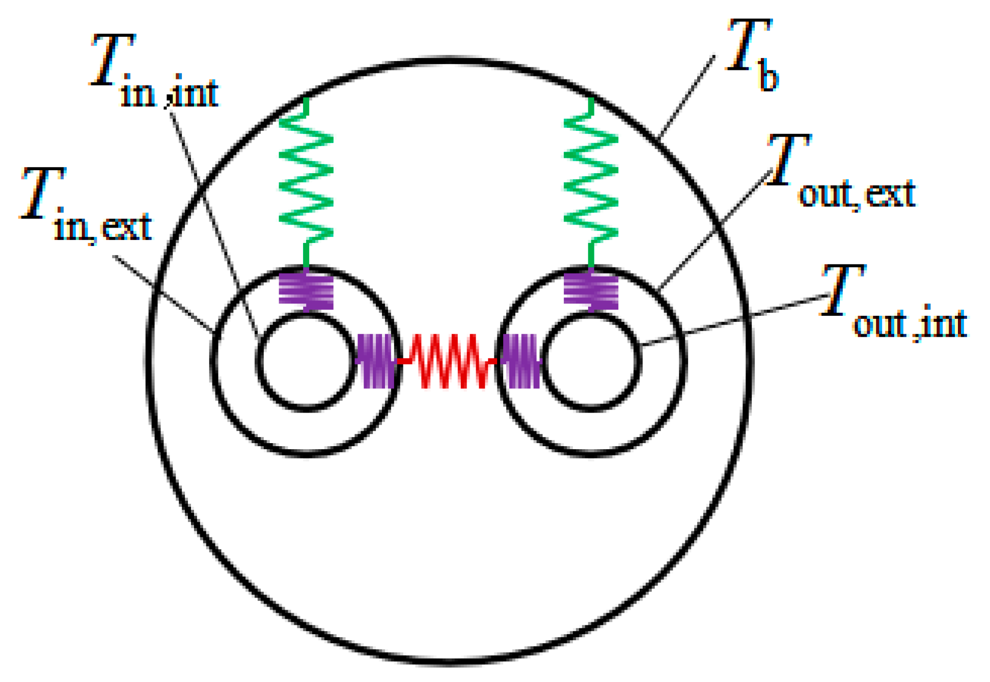
The heat transfer between the borehole wall and the tube was only considered in Sharqawy et al.’s method [48] and the corresponding calculating model is shown in Figure 9. Combining the setting law of Sharqawy et al.’s temperature and the ground temperature distribution characteristics in this paper, the boundary temperature of the model was set under the premise of cooling working conditions. The temperature of borehole wall Tb, inlet tube Tin,int, and outlet tube Tout,int were set to 20, 30, and 25 °C, respectively; the material parameters were the same as in Table 2. The temperature in the borehole can reach a stable state within a short time due to the small size of the borehole section, thus, the steady-state analysis was adopted. To more accurately explain the heat exchange efficiency of tubes with different shapes, the model of the heat exchange between tubes (Tin,int = 30 °C, Tout,int = 25 °C) and the model of heat exchange between the tube and borehole wall (Tin,int = 25 °C, Tb = 20 °C) were established.
Figure 10 plots the heat resistance of BHEs with 3D and 2D models in [48] with different section shapes. One can notice that the heat resistance values of the two methods are similar. The heat resistances of tubes with different cross-sectional shapes, in increasing order, are flat oval, sector, curved oval, semicircle, and circle. The differences in heat resistance with different cross-sectional shapes can be explained in terms of heat exchange efficiency between two legs and the heat exchange efficiency between the tube and borehole wall, which are detailed below.
To more accurately explain the heat distribution characteristics inside the borehole, the middle depth of the borehole was selected as a typical borehole section, and the temperature cloud is illustrated in Figure 11.
Figure 11 shows the temperature distribution of BHEs with different tube shapes after 48 h and at a 50 m depth. It can be found that the fluid temperature in the tube is evenly distributed and heat exchange is conducted through the tube, backfill soil, borehole wall, and the soil. Under the same fluid area (531 mm2), a large difference appears at the heat exchange perimeter, and the corresponding relationship in decreasing order is flat-oval shape (98.9 mm), semicircle shape (94.5 mm), sector shape (92.84 mm), curved oval shape (89.04 mm), and circle shape (81.68 mm).
Figure 12 depicts the temperature distribution of BHEs with different tube shapes at the given tube temperatures. We found that the temperature distribution of BHEs is different for different tube shapes, which can be used to reflect the heat short-circuit effect between two legs. The description of the heat short-circuit effect in BHEs is that the heat exchange occurs between fluid in two legs rather than fluid to soil [15,47], and the existence of a heat short-circuit will reduce the heat exchange efficiency of BHEs. Hence, in this study, we recognized the effective evaluation of heat short-circuit between fluid in two legs as the heat flux value between two legs. The heat flux between two legs for circle, curved oval, flat oval, semicircle, and sector tubes were 11.133, 11.601, 12.198, 11.836, and 11.327 W/m, respectively, in which the higher heat flux indicates a greater heat short-circuit effect. The corresponding relationship with the heat short-circuit effect, in decreasing order, is flat oval, semicircle, curved oval, sector, and circle tubes. This finding can be explained by the combined effect of the heat exchange perimeter of the tube and the relative distance between tubes [12,13]. The larger the heat exchange perimeter of a tube and the smaller relative distance between tubes, the more obvious the heat short-circuit effect.
Figure 13 indicates the temperature distribution of BHEs with different-shaped tube at the given tube and borehole wall temperatures. We found that the temperature distribution and heat transfer direction are all different at different tube shapes. Due to the differences in tube geometry and distribution characteristics, the heat flux values between the borehole wall and circle, curved oval, flat oval, semicircle, and sector tubes were: 28.8, 30.8, 33.2, 30.2, and 30.5 W/m, respectively, in which a higher heat flux indicates a greater heat exchange efficiency of the tube to the borehole wall. The corresponding affecting relationship of the heat exchange efficiency of the tube to borehole wall, in decreasing order, is flat oval, curved oval, sector, semicircle, and circle tubes. These can be explained by the combined effect of the heat exchange perimeter of tube and relative distance of the tube to borehole wall. The larger the heat exchange perimeter of a tube and the smaller relative distance of tube to borehole wall, the higher heat exchange efficiency of tube to borehole wall.
Based on Sharqawy et al.’s theory [48] the heat exchange efficiency of BHEs is related to the heat exchange efficiency of the tube to the borehole wall and the heat short-circuit effect between two legs. The greater the heat exchange efficiency of the tube to the borehole wall and the less the heat short-circuit effect between legs, the greater the heat exchange efficiency of BHEs (less heat resistance).
For flat oval tubes, as shown in Figure 14c, the heat flux between the tube and the borehole wall was the greatest, much larger than that of other shapes. Therefore, even if the heat short-circuit effect of the flat oval tube is obvious, it still has a higher heat exchange efficiency, which means a lower heat resistance of 1.251 m·K/W.
For circle-shaped tubes, as shown in Figure 14a, the heat exchange efficiency of the tube to the borehole wall was the lowest, being much lower than that of other shapes. Therefore, even if the heat short-circuit effect of the circular tube is the lowest, it still has a smaller heat exchange efficiency, which means a greater heat resistance of 1.433 m·K/W.
For semicircle-shaped tubes, as shown in Figure 14d, the heat exchange efficiency of the tube to the borehole wall and the heat short-circuit effect of the tube were both larger than those of the circular tube. However, the influence of heat short-circuit between two legs was less than that of the heat exchange efficiency of the tube to the borehole wall. Hence, the tube with semicircle shape still has a higher heat exchange efficiency than the circular tube, resulting in a lower heat resistance of 1.360 m·K/W.
Comparing the curved oval and sector tubes, as shown in Figure 14b,e, we found that the heat exchange efficiency of the sector-shaped tube to the borehole wall was larger than that of the curved oval tube, and the heat exchange efficiency between two legs with a sector-shaped tube was lower than for curved oval tubes. Under the combined effect of the both, the heat exchange efficiency of the sector-shaped tubes in BHEs was greater than that of the curved oval tube. In other words, the heat resistance of the tube with a sector shape (1.318 m·K/W) was lower than that of the curved oval tube (1.344 m·K/W).
As shown in Figure 10, we found that the calculated heat resistance with Sharqawy et al.’s method [48] is similar to that calculated using the 3D model. The calculation errors of the two methods were less than 2%, which means that with constant legs distance, Sharqawy et al.’s method can be used to estimate the heat resistance considering different tube shapes [48].
4.4. Temperature Distribution of U-Tube
Serageldin et al. [13,39] stated that during the BHEs cooling process, the drop in fluid temperature is non-uniform, which is related to the soil temperature. Due to the shorter distance between two BHE legs, the heat short-circuit effect affects the temperature distribution between two legs. The temperature distribution of BHEs with different tube shapes along the depth at 48 h is shown in Figure 15.
Figure 15 shows that the temperature at the inlet side drops more rapidly than on the outlet side with increasing depth, and fewer temperature changes appear when the depth is less than 5 m. In the BHE cooling process, hotter fluid flows into the tube after experiencing the heat exchange with soil, then flows out from the outlet. According to the heat exchange law (heat is always exchanged from high to low temperature) and the temperature distribution results in Figure 15, we concluded that the temperature on the inlet side Tin is higher than the temperature on the outlet side Tout, and both are higher than the soil temperature Tsoil. On the inlet side, the fluid heat transfers to the soil and to the fluid on the outlet side; on the outlet side, the fluid heat transfers to the soil and to the fluid on the inlet side, but the higher temperature on the inlet side will reduce the heat transfer efficiency of the fluid on the outlet side due to the heat short-circuit effect. Hence, the heat exchange of the fluid on the inlet side is more efficient than that of the fluid on the outlet side, undergoing a higher temperature drop at the inlet side than on the outlet side. Furthermore, less of a temperature change was observed within a depth of 5 m. This can be explained by the higher soil temperature (shown in Figure 2) that reduces the heat exchange efficiency of fluid to soil. Therefore, when designing the length of BHEs, the depth of soil that is easily affected by seasonal temperature should be considered to maintain the BHE efficiency.
Figure 16 depicts the heat flow of two legs with different shapes. We found that the heat flux on the inlet side and outlet side differed due to the heat exchange between two tubes. On the inlet side, the heat fluxes of circle, curved oval, flat oval, semicircle, and sector tubes were 27.93, 28.22, 28.99, 28.54, and 28.13 W/m, respectively; on the outlet side, the heat fluxes were 17.88, 17.59, 16.82, 17.27, and 17.68 W/m, respectively. According to the discussion in Section 4.3 and Serageldin’s studies, the larger the heat flux difference between the inlet and outlet sides, the more obvious the heat short-circuit effect. Hence, we concluded that the relationship between the heat short-circuit and tube shapes in decreasing order is flat oval shape, semicircle shape, curved oval shape, sector shape, and circle shape; the tendency is consistent with the discussion in Section 4.3.
4.5. Borehole Wall Temperature
In the engineering of BHEs, due to the influence of fluid temperature, tube shapes, and distribution characteristics of the tube, the temperature of the borehole wall is usually non-uniform, which plays an important role in determining the heat affecting radius. Hence, the temperature distribution at the borehole wall must be studied considering different tube shapes. In the analysis, to more accurately determine the influence of tube shape on borehole wall temperature, referring to the temperature distribution characteristics in Figure 13, the fluid temperature on the inlet and outlet sides were set to constant values of 30 and 28 °C, respectively, and the corresponding model and results are shown in Figure 17.
Figure 17 shows that the temperature distribution along the borehole wall is non-uniform and the tendency is similar for different tube shapes. Comparing the maximum and minimum temperatures of the borehole wall with different tube shapes, we found that temperature difference between the maximum and minimum along the borehole wall in decreasing order is circle, sector, curved oval, flat oval, and semicircle tubes. The influence of tube shape on borehole wall temperature can be explained in terms of the heat exchange perimeter and the heat resistance of the tube to the borehole wall.
5. Heat Resistance under Different Leg Distances
5.1. Control of Leg Distance
During the sinking of the U-tube, to ensure the distance between the two legs, a limit device is generally used. Figure 16 shows two typical U-tube limit devices. Figure 18a is a fixed limit device with constant spacing, which was used in the TRTs. In engineering, after the drilling is completed, the soil with low strength inside the borehole springs back under the action of lateral soil pressure, which means the borehole diameter will decrease. Hence, if using a fixed limit device, for overcoming the problem of the U-tube sticking in the borehole, the designed distance between two legs of a U-tube usually is less than the borehole. Figure 18b depicts an elastic limit device that can make U-type legs contact with the borehole wall, which maximizes the distance between the two legs. However, if the borehole wall is weak or the backfill soil is late, it is possible to lose the desired effect due to the elastic force being lower than the lateral soil force. The above two limit devices are both common in BHEs engineering; hence, to better support engineering of BHEs, the maximum leg distance of tubes with different shapes was considered and the corresponding results are shown in Figure 19 and Figure 20.
5.2. Heat Resistance with Different Leg Distances
Figure 19 shows that the heat resistance at maximum legs distance is lower than at constant leg distance. Comparing the temperatures in Figure 11 and Figure 20, we concluded that the greater the distance between the two legs, the higher the heat exchange efficiency between the fluid and the smaller the heat short-circuit effect. Hence, heat resistance decreases with the increase in leg distance.
With increasing leg distance, the heat resistance reduced from 1.43 to 1.1 for circle tubes, about 23.2%; reduced from 1.34 to 0.96 for curved oval tubes, about 28.4%; reduced from 1.25 to 0.91 for flat oval tubes, about 27.7%, reduced from 1.36 to 0.99 for semicircle tubes, about 27.4%,; and for sector-shaped tubes, reduced from 1.32 to 1.01, about 23.1%. Hence, the influence of leg distance and tube shapes in reducing order is curved oval, flat oval shape, semicircle, circle, and sector tubes.
Comparing the heat resistance of tubes with different shapes, it can be noted that at maximum leg distance, the heat resistance of flat-oval-shaped tubes was the lowest (0.91 m·K/W), which is a 17.7% reduction compared to circle-shaped tubes; the heat resistance of curved-oval-shaped tube is 0.96 m·K/W, which is a 12.6% reduction compared to the circle-shaped tube; 0.99 m·K/W for the semicircle-shaped tube, which is a 10.3% reduction compared to the circular tube; 1.01 m·K/W for the sector-shaped tube, which is a 7.8% reduction compared to the circle-shaped tube; and the heat resistance of the sector-shaped tube was the biggest, 1.10 m·K/W. Hence, at the maximum leg distance, the heat resistance of the different-shaped tubes in increasing order is flat oval, curved oval, semicircle, sector, and circle.
Based on above analysis, we concluded that the adjustment of the leg distance will affect the heat resistance by about 25% and the adjustment of the tube shape will affect the heat resistance by about 12%. Hence, in engineering design, the leg distance should be considered first, followed by changing tube shape; the flat-oval-shaped tube at maximum leg distance is the best tube design for BHEs of the designs considered.
6. Conclusions
For improving the heat exchange efficiency of BHEs and reducing initial investment, based on TRTs and COMSOL Multi-physics, the heat transfer characteristics of BHEs with different cross-sectional tubes (circular, curved ellipse, straight ellipse, semicircle, and sector) were studied using 3D numerical analysis. The corresponding conclusions are described as follows:
- (1)
- Based on TRTs, we verified the reliability of using COMSOL Multi-physics with three-dimensional models to study the heat exchange characteristic of BHEs.
- (2)
- Compared with the inlet and outlet temperatures of the tube with a circle shape at 48 h, the results show that the heat exchange efficiency of the curved oval tube increases by 13.0%, the flat oval tube by 19.1%, the semicircle tube by 9.4%, and sector tube by 14.8%.
- (3)
- The heat flux heterogeneity of the tube on the inlet and outlet sides in BHEs with different tube shapes in decreasing order is flat oval shape, semicircle shape, curved oval shape, sector shape, and circle shape.
- (4)
- The temperature heterogeneity of the borehole wall in BHEs with different tube shapes in decreasing order is circle shape, sector shape, curved oval shape, flat oval shape, and semicircle shape.
- (5)
- Compared with the heat resistance of the circle-shaped tube at 48 h, we found that the heat resistance of the curved oval tube decreased by 12.6%, the flat oval tube by 17.7%, the semicircle tube by 10.3%, and the sector tube by 7.8% at maximum leg distance.
- (6)
- The adjustment of the leg distance affects the heat resistance by about 25% and the adjustment of the tube shape affects the heat resistance by about 12%.
- (7)
- The adjustment of tube shape can improve the heat exchange efficiency of BHEs, and the flat-oval-shaped tube at maximum leg distance was found to be the best tube design for BHEs.
It is worth noting that the influence of tube cross-section shape on heat transfer characteristics of BHEs at 48 h was studied by combining TRT and a 3D model in this work. To better serve the project about BHEs, long-term BHE heat transfer characteristics (1–10 years) and cyclic loading (cooling and heating) will be investigated according to monitoring data in future research.
Author Contributions
Conceptualization: A.Z., X.H., W.W., and P.J.; methodology: A.Z. and X.L.; software: X.H.; validation: W.W. and P.J.; formal analysis: A.Z., W.W., and X.H.; investigation: W.W.; resources: X.H.; data curation: X.H. and X.L.; writing—original draft preparation: X.H.; writing—review and editing: A.Z., W.W., and P.J.; visualization: A.Z.; supervision: X.H.; project administration: X.H.; funding acquisition: A.Z. and P.J. All authors have read and agreed to the published version of the manuscript.
Funding
This research was funded by the National Natural Science Foundation of China grant numbers 51579119 and 41772311. The APC was funded by A.Z.
Data Availability Statement
The data presented in this study are available on request from the corresponding author.
Conflicts of Interest
The authors declare no conflict of interest.
References
- Wu, G.; Wang, H.J.; Wu, Q.G. Wind power development in the Belt and Road area of Xinjiang, China: Problems and solutions. Util. Policy 2020, 101024. [Google Scholar] [CrossRef]
- Domfeh, M.K.; Mark, S.G.; Robert, A.; Antwi, E.; Tabor, G. Free surface vortices at hydropower intakes: A state-of-the-art review. Sci. Afr. 2020, 21, e355. [Google Scholar] [CrossRef]
- Harcourt, F.; Angeloudis, A.; Piggott, M.D. Utilising the flexible generation potential of tidal range power plants to optimise economic value. Appl. Energy 2019, 237, 873–884. [Google Scholar] [CrossRef] [Green Version]
- Wang, Y.Q.; Liu, Y.X.; Dou, J.Y.; Li, M.Z.; Zeng, M. Geothermal energy in China: Status, challenges, and policy recommendations. Util. Policy 2020, 64, 101020. [Google Scholar] [CrossRef]
- Kumar, S.; Gupta, S.K.; Rawat, M. Resources and utilization of geothermal energy in India: An Eco—Friendly approach towards sustainabilit. Mater. Today Proc. 2020, 13. [Google Scholar] [CrossRef]
- Huang, X.W.; Zhou, A.Z.; Wang, W.; Jiang, P.M. Characterization of the dynamic properties of clay–gravel mixtures at low strain level. Sustainability 2020, 4, 1616. [Google Scholar] [CrossRef] [Green Version]
- Xu, B.; Zhang, H.Z.; Chen, Z.Q. Study on heat transfer performance of geothermal pile-foundation heat exchanger with 3-U pipe configuration. Int. J. Heat Mass. Tran. 2020, 147, 119020. [Google Scholar] [CrossRef]
- Younas, U.; Khan, B.; Ali, S.M.; Arshad, C.M.; Vaccaro, A. Pakistan geothermal renewable energy potential for electric power generation: A survey. Renew. Sustain. Energy Rev. 2016, 63, 398–413. [Google Scholar] [CrossRef]
- Kerme, E.D.; Fung, A.S. Heat transfer simulation, analysis and performance study of single U-tube borehole heat exchanger. Renew. Energy 2020, 145, 1430–1448. [Google Scholar] [CrossRef]
- Zhang, W.K.; Yang, H.X.; Diao, N.R.; Lu, L.; Fang, Z.H. Exploration on the reverse calculation method of groundwater velocity by means of the moving line heat source. Int. J. Therm. Sci. 2016, 99, 52–63. [Google Scholar] [CrossRef]
- Li, H.; Xi, C.; Kong, X.F.; Lin, Z.; Wang, L. A comparative experimental investigation on radiant floor heating system and stratum ventilation. Sustain. Cities Soc. 2020, 52, 101823. [Google Scholar] [CrossRef]
- Jahanbin, A. Thermal performance of the vertical ground heat exchanger with a novel elliptical single U-tube. Geothermics 2020, 86, 101804. [Google Scholar] [CrossRef]
- Serageldin, A.; Sakata, Y.; Katsura, T.; Nagano, K. Thermo-hydraulic performance of the U-tube borehole heat exchanger with a novel oval cross-section: Numerical approach. Energy Convers. Manag. 2018, 177, 406–415. [Google Scholar] [CrossRef]
- Narei, H.; Fatehifar, M.; Ghasempour, R.; Noorollahi, Y. In pursuit of a replacement for conventional high-density polyethylene tubes in ground source heat pumps from their composites—A comparative study. Geothermics 2020, 87, 101819. [Google Scholar] [CrossRef]
- Zanchini, E.; Jahanbin, A. Effects of the temperature distribution on the thermal resistance of double u-tube borehole heat exchangers. Geothermics 2018, 71, 46–54. [Google Scholar] [CrossRef]
- Zhu, L.; Chen, S.; Yang, Y.; Sun, Y. Transient heat transfer performance of a vertical double U-tube borehole heat exchanger under different operation conditions. Renew. Energy 2019, 131, 494–505. [Google Scholar] [CrossRef]
- Eicker, U.; Vorschulze, C. Potential of geothermal heat exchangers for office building climatisation. Renew. Energy 2009, 34, 1126–1133. [Google Scholar] [CrossRef]
- Lund, J.W.; Boyd, T.L. Direct utilization of geothermal energy 2015 worldwide review. Geothermics 2016, 60, 66–93. [Google Scholar] [CrossRef]
- Choab, N.; Allouhi, A.; Maakoul, A.E.; Kousksou, T.; Jamil, A. Review on greenhouse microclimate and application: Design parameters, thermal modeling and simulation, climate controlling technologies. Sol. Energy 2019, 191, 109–137. [Google Scholar] [CrossRef]
- Gajewski, A.; Gładyszewska, F.K.; Krawczyk, D.A. Carbon dioxide emissions during air, ground, or groundwater heat pump performance in białystok. Sustainability 2019, 18, 5087. [Google Scholar] [CrossRef] [Green Version]
- Marrasso, E.; Roselli, C.; Sasso, M.; Tariello, F. Global and local environmental and energy advantages of a geothermal heat pump interacting with a low temperature thermal micro grid. Energy Convers. Manag. 2018, 172, 540–553. [Google Scholar] [CrossRef]
- Wua, S.Y.; Daib, Y.C.; Lic, X.L.; Opponga, F.; Xu, C.S. Assessing the feasibility of using the heat demand-outdoor temperature function for a long-term district heat demand forecast. Energy Procedia 2018, 152, 413–418. [Google Scholar] [CrossRef]
- Ma, W.; Kim, M.K.; Hao, J. Numerical Simulation Modeling of a GSHP and WSHP System for an Office Building in the Hot Summer and Cold Winter Region of China: A Case Study in Suzhou. Sustainability 2019, 12, 3282. [Google Scholar] [CrossRef] [Green Version]
- Blomqvist, S.; La Fleur, L.; Amiri, S.; Rohdin, P.; Trygg, L.Ö.F. The impact on system performance when renovating a multifamily building stock in a district heated region. Sustainability 2019, 8, 2199. [Google Scholar] [CrossRef] [Green Version]
- Blum, P.; Campillo, G.; Kölbel, T. Techno-economic and spatial analysis of vertical ground source heat pump systems in Germany. Energy 2011, 5, 3001–3011. [Google Scholar] [CrossRef]
- Karytsas, S.; Choropanitis, I. Barriers against and actions towards renewable energy technologies diffusion: A Principal Component Analysis for residential ground source heat pump (GSHP) systems. Energy Rev. 2017, 78, 252–271. [Google Scholar] [CrossRef]
- Lu, Q.; Narsilio, G.A.; Aditya, G.R.; Johnston, I.W. Cost and performance data for residential buildings fitted with GSHP systems in Melbourne Australia. Data Brief. 2017, 12, 9–12. [Google Scholar] [CrossRef] [PubMed]
- Robert, F.; Gosselin, L. New methodology to design ground coupled heat pump systems based on total cost minimization. Appl. Therm. Eng. 2014, 2, 281–291. [Google Scholar] [CrossRef]
- Wu, S.Y.; Dai, Y.C.; Li, X.L.; Oppong, F.; Xu, C.S. A review of ground-source heat pump systems with heat pipes for energy efficiency in buildings. Energy Procedia 2018, 152, 413–418. [Google Scholar] [CrossRef]
- Karytsas, S.C.; Chaldezos, I.P. Review of the greek legislative framework for ground source heat pumps (gshps) and suggestions for its improvement. Procedia Environ. Sci. 2017, 38, 704–712. [Google Scholar] [CrossRef]
- Zhou, J.; Ding, M.; Bian, H.Z.; Zhang, Y.X.; Sun, Z.N. CFD simulation for the effect of the header match on the flow distribution in a central-type parallel heat exchanger. Chem. Eng. Res. Des. 2018, 136, 144–153. [Google Scholar] [CrossRef]
- Danielewicz, J.; Śniechowska, B.; Sayegh, M.A.; Fidorów, N.; Jouhara, H. Three-dimensional numerical model of heat losses from district heating network pre-insulated pipes buried in the ground. Energy 2016, 108, 172–184. [Google Scholar] [CrossRef] [Green Version]
- Gerlich, V.; Sulovská, K.; Zálešák, M. COMSOL Multiphysics validation as simulation software for heat transfer calculation in buildings: Building simulation software validation. Measurement 2013, 6, 2003–2012. [Google Scholar] [CrossRef] [Green Version]
- Bryś, K.; Bryś, T.; Sayegh, M.A.; Ojrzyńska, H. Characteristics of heat fluxes in subsurface shallow depth soil layer as a renewable thermal source for ground coupled heat pumps. Renew. Energy 2020, 146, 1846–1866. [Google Scholar] [CrossRef]
- Sayegh, M.A.; Jadwiszczak, P.; Axcell, B.P.; Niemierka, E.; Bryś, K.; Jouhara, H. Heat pump placement, connection and operational modes in European district heating. Energy Build. 2018, 166, 122–144. [Google Scholar] [CrossRef]
- Bryś, K.; Bryś, T.; Sayegh, M.A.; Ojrzyńska, H. Subsurface shallow depth soil layers thermal potential for ground heat pumps in Poland. Energy Build. 2018, 165, 64–75. [Google Scholar] [CrossRef]
- Zhang, C.X.; Xu, H.; Fan, J.H.; Sun, P.K.; Sun, S.C.; Kong, X.Q. The coupled two-step parameter estimation procedure for borehole thermal resistance in thermal response test. Renew. Energy 2020, 154, 672–683. [Google Scholar] [CrossRef]
- Marcotte, B.; Bernier, M. Experimental validation of a TRC model for a double U-tube borehole with two independent circuits. Appl. Therm. Eng. 2019, 162, 114–229. [Google Scholar] [CrossRef]
- Zhou, K.; Mao, J.F.; Li, Y.; Xiang, J.Y. Parameters optimization of borehole and internal thermal resistance for single U-tube ground heat exchangers using Taguchi method. Energy Convers. Manag. 2019, 201, 112177. [Google Scholar] [CrossRef]
- Javadi, H.; Ajarostaghi, S.S.M.; Rosen, M.A.; Pourfallah, M. Performance of ground heat exchangers: A comprehensive review of recent advances. Energy 2019, 178, 207–233. [Google Scholar] [CrossRef]
- Suzukia, M.; Yoneyam, K.; Amemiy, S.; Motoaki, O. Development of a spiral type heat exchanger for ground source heat pump system. Energy Procedia 2016, 503, 503–510. [Google Scholar] [CrossRef] [Green Version]
- Zhang, L.F.; Luo, X.W.; Huang, G.S.; Zhang, Q. Comparative analysis of U-pipe location on the sizing of borehole heat exchangers. Appl. Therm. Eng. 2019, 150, 666–673. [Google Scholar] [CrossRef]
- Marzena, N.O.; Ocłoń, P. Thermal and economic analysis of preinsulated and twin-pipe heat network operation. Energy 2020, 193, 116619. [Google Scholar] [CrossRef]
- Arif, W.; Shrestha, G.; Takeshi, I.; Kasumi, Y.; Youhei, U.; Mayumi, Y. Using a capillary mat as a shallow heat exchanger for a ground source heat pump system. Energy Build. 2020, 209, 109684. [Google Scholar] [CrossRef]
- Abuhamdeh, N.H.; Bantan, R.A.R.; Tlili, I. Analysis of the thermal and hydraulic performance of the sector-by-sector helically coiled tube heat exchangers as a new type of heat exchangers. Int. J. Therm. Sci. 2020, 150, 106229. [Google Scholar] [CrossRef]
- Technical Code for Ground-Source Heat Pump System. In GB 50366-2009; China Construction Industry Press: Beijing, China, 2009; Available online: http://www.doc88.com/p-9773941498889.html (accessed on 12 March 2021).
- Javed, S.; Spitler, J. Accuracy of borehole thermal resistance calculation methods for grouted single U-tube ground heat exchangers. Appl. Energy 2017, 187, 790–806. [Google Scholar] [CrossRef]
- Sharqawy, M.H.; Mokheimer, E.M.; Badr, H.M. Effective pipe-to-borehole thermal resistance for vertical ground heat exchangers. Geothermics 2009, 38, 271–277. [Google Scholar] [CrossRef]
Figure 1.
Thermal response test site.

Figure 2.
Temperature distribution along borehole depth.

Figure 3.
Numerical models. (a) Model size and meshing result; (b) boundary condition.

Figure 4.
Cross-sections of the studied tube shapes. (a) Circle tube; (b) curved-oval tube; (c) flat-oval tube; (d) semicircle tube; and (e) sector tube.
Figure 4.
Cross-sections of the studied tube shapes. (a) Circle tube; (b) curved-oval tube; (c) flat-oval tube; (d) semicircle tube; and (e) sector tube.

Figure 5.
Heating water tank model with rated power.

Figure 6.
Numerical model verification.

Figure 7.
Temperature curves of the inlet and outlet of a tube.

Figure 8.
Inlet and outlet temperature at 48 h.

Figure 9.
Sharqawy et al.’s heat resistance model [48].
Figure 9.
Sharqawy et al.’s heat resistance model [48].

Figure 10.
Thermal resistance with different calculation methods.

Figure 11.
Temperature distribution of borehole with 3D models. (a) Circle tube; (b) curved-oval tube; (c) flat-oval tube; (d) semicircle tube; and (e) sector tube.
Figure 11.
Temperature distribution of borehole with 3D models. (a) Circle tube; (b) curved-oval tube; (c) flat-oval tube; (d) semicircle tube; and (e) sector tube.

Figure 12.
Temperature distribution of borehole between two legs. (a) Circle tube; (b) curved-oval tube; (c) flat-oval tube; (d) semicircle tube; and (e) sector tube.
Figure 12.
Temperature distribution of borehole between two legs. (a) Circle tube; (b) curved-oval tube; (c) flat-oval tube; (d) semicircle tube; and (e) sector tube.

Figure 13.
Temperature distribution of a borehole between tube and borehole wall. (a) Circle tube; (b) curved-oval tube; (c) flat-oval tube; (d) semicircle tube; and (e) sector tube.
Figure 13.
Temperature distribution of a borehole between tube and borehole wall. (a) Circle tube; (b) curved-oval tube; (c) flat-oval tube; (d) semicircle tube; and (e) sector tube.

Figure 14.
Heat flux distribution of borehole with 3D models. (a) Circular tube; (b) curved-oval tube; (c) flat-oval tube; (d) semicircle tube; and (e) sector tube.
Figure 14.
Heat flux distribution of borehole with 3D models. (a) Circular tube; (b) curved-oval tube; (c) flat-oval tube; (d) semicircle tube; and (e) sector tube.

Figure 15.
Tube temperature distribution along the depth at 48 h.

Figure 16.
Average heat flow of two legs with different shapes.

Figure 17.
Temperature distribution of borehole wall.

Figure 18.
Limit device of U-shaped tube. (a) Limit device with fixed distance; (b) limit device with elastic distance.
Figure 18.
Limit device of U-shaped tube. (a) Limit device with fixed distance; (b) limit device with elastic distance.

Figure 19.
Heat resistance of different tube shapes.

Figure 20.
Temperature distribution at maximum leg distance. (a) Circle tube; (b) curved-oval tube; (c) flat-oval tube; (d) semicircle tube; and (e) sector tube.
Figure 20.
Temperature distribution at maximum leg distance. (a) Circle tube; (b) curved-oval tube; (c) flat-oval tube; (d) semicircle tube; and (e) sector tube.


Table 1.
Soil parameters.
| No. | Depth (m) | Structure | No. | Depth (m) | Structure |
|---|---|---|---|---|---|
| 1 | 1 | Plain fill | 5 | 62 | Moderately weathered conglomerate |
| 2 | 18 | Silt clay | 6 | 84 | Moderately weathered mudstone |
| 3 | 21.5 | Strongly weathered mudstone | 7 | 92 | Fully glutenite |
| 4 | 40.5 | Moderately weathered argillaceous sandstone | 8 | 101 | Moderately weathered mudstone |
Table 2.
Material parameters.
| Parameter | Unit | Soil | Backfill | Tube | Fluid |
|---|---|---|---|---|---|
| Density | kg/m3 | 1800 | 1800 | 1000 | 995.03 |
| Specific heat | J/(kg K) | 1353 | 1353 | 1824 | 4179.5 |
| Heat conductivity | W/(m K) | 2.39 | 2.39 | 0.4 | 0.6187 |
Table 3.
Characteristic description of the cross-section.
| Section Shape | Characteristic Size (mm) |
|---|---|
| Circle | Diameter dt: 26; angle: 360° |
| Curved-oval | Long axis h: 36.76; short axis w:18.38 |
| Flat-oval | Long axis h: 27.71; short axis x: 13.81 |
| Semicircle | Diameter dt: 36.76; angle:180° |
| Sector | Diameter dt: 52; angle: 90° |
Publisher’s Note: MDPI stays neutral with regard to jurisdictional claims in published maps and institutional affiliations. |
© 2021 by the authors. Licensee MDPI, Basel, Switzerland. This article is an open access article distributed under the terms and conditions of the Creative Commons Attribution (CC BY) license (http://creativecommons.org/licenses/by/4.0/).
Share and Cite
MDPI and ACS Style
Zhou, A.; Huang, X.; Wang, W.; Jiang, P.; Li, X. Thermo-Hydraulic Performance of U-Tube Borehole Heat Exchanger with Different Cross-Sections. Sustainability 2021, 13, 3255. https://0-doi-org.brum.beds.ac.uk/10.3390/su13063255
AMA Style
Zhou A, Huang X, Wang W, Jiang P, Li X. Thermo-Hydraulic Performance of U-Tube Borehole Heat Exchanger with Different Cross-Sections. Sustainability. 2021; 13(6):3255. https://0-doi-org.brum.beds.ac.uk/10.3390/su13063255
Chicago/Turabian StyleZhou, Aizhao, Xianwen Huang, Wei Wang, Pengming Jiang, and Xinwei Li. 2021. "Thermo-Hydraulic Performance of U-Tube Borehole Heat Exchanger with Different Cross-Sections" Sustainability 13, no. 6: 3255. https://0-doi-org.brum.beds.ac.uk/10.3390/su13063255
Note that from the first issue of 2016, this journal uses article numbers instead of page numbers. See further details here.