Article

Evaluation of Prospective Use of Existed CFRP-Strengthened Concrete Pipes in Forest Areas: Assessment of Their Structural Stability and Possible Re-Use

by
Rigas Giovannopoulos
1 and
Konstantinos Katakalos
2,*
1
Department of Forestry and Natural Environment, Faculty of Agriculture, Aristotle University of Thessaloniki, 54124 Thessaloniki, Greece
2
Laboratory for Strength of Materials and Structures, Department of Civil Engineering, Faculty of Engineering, Aristotle University of Thessaloniki, 54124 Thessaloniki, Greece
*
Author to whom correspondence should be addressed.
Sustainability 2021, 13(9), 4947; https://0-doi-org.brum.beds.ac.uk/10.3390/su13094947
Submission received: 5 April 2021 / Accepted: 24 April 2021 / Published: 28 April 2021
(This article belongs to the Collection Sustainable Built Environment)

Abstract

:
Forest traffic networks receive considerable structural stress from supporting heavy vehicles and machinery. Usually, in forest areas, artificial waterways are constructed on the side of the road and feature open constructions, so that solid materials blocking the waterways may be easily cleared. The use of closed bridges at vehicle crossing points, though infrequent, necessitates the use of installing closed water pipelines of large diameters. However, these closed, reinforced concrete (RC) water pipelines suffer structural damage over time. Here, we propose the strengthening of existed old concrete pipes using sheets of carbon fiber reinforced polymer (CFRP) at increasing levels. The assessment of the results, which were conducted in ABAQUS, is done in light of the stress tests and suggests that the use of a simple, cost-effective method, such as the installation of composite materials, can potentially increase the structural strength of these pipes and allow their re-use for forest roads.

1. Introduction

1.1. Forest Roads

Road and infrastructure construction is considered to be an essential part of forestry as forests become sustainable and profitable only if they are connected with a suitable road network, (see, for example, road network assessments in Europe [1], Turkey [2], the Himalayas [3], and the Amazon [4]). With the construction of forest roads, any forest can potentially be opened for financial gain and sustainable maintenance; they are the skeleton of integrated openings of forests, mountains, etc., and are the basis for any activity. An integral part of forest roads are side road projects, which serve a functional and protective role, and compose, together with the road tarmac, the overall image of the forest road. Amongst the wide variety of side road projects are the technical works for the protection of water slopes along forest roads. A key feature is the drainage of water across forest roads in a manner that can guarantee its usability and road worthiness, as failure to provide adequate drainage along forest roads can have wide-ranging negative results [5].
A predominant issue with road projects in forest roads is maintaining uniformity and compatibility between construction works and the surrounding environment, while at the same time such works require a good adaptation to the terrain [6]. The traffic load on forest roads is small, therefore forest roads with one lane are justified provided that appropriate widening points are provided for the intersection and return of vehicles [7]. Large loads are transported on forest roads, so a stable foundation and base are not only required but an absolute necessity.
Adjacent water drainage support projects ideally facilitate the harmonious connection of the road with the landscape, adapting to the image of the surrounding landscape with appropriate configurations of their shape and with a utilization of the correct choice of materials. Occasionally, water drainage may include culverts that have a diameter opening of up to 4 m. Culverts that run under a forest road may be separated based on the shape of their cross-section: tubular, slate, vaulted, and boxed. They may be further separated based on their construction materials: stone, (reinforced) concrete, iron, and wood. In order to be able to cope with extensive weight loads, prestressed concrete pipes are now in use for water drainage in forest areas where trucks carrying timber are passing through (for typical characteristics of prestressed concrete pipes see [8]). The structural qualities of prestressed concrete pipes, such as their sturdiness and their hydrostatic pressure bearing capacity, in conjunction with the possibility of constructing pipes of large diameters, make them highly preferable for use not only in forestry but also in agricultural, urban, and industrial projects. As they are tubular-shaped, when their entrances and exits are properly designed, they are better adapted to the forest landscape and can be used at cross-sections where the forest road’s path may lead it to go over a water drainage point [9].
Prestressed pipes are composed of a concrete core, high-tensile steel wires spirally wound around the concrete, occasionally incorporated steel cylinders embedded in concrete, and a mortar coating layer. The prestressing wires are typically designed to withstand the entire hydrostatic pressure. However, they are susceptible to corrosion, hydrogen embrittlement, and are also prone to manufacturing or installation defects. As a result, the prestressing wires supporting the hydrostatic load may break unexpectedly. If many wires break, the pipe’s bearing capacity is decreasing substantially. Eventually, pipe ruptures occur with potentially impactful consequences.

1.2. CFRP Strengthening of Re-Used RC Pipes

Our primary interest lies in providing a cost-effective structural strengthening process of concrete water pipes intended to be re-used and placed in forest roads. In order to withstand immense pressures from both inside and outside, water supply engineers spend copious amounts of time so as to assess the wire-breaking process of structures of prestressed and reinforced concrete pipes and propose remedial plans.
There have been a number of proposals aiming to provide structural strength to concrete pipes, without necessarily making use of prestressed steel bars, when they are ruptured and in need of replacement. Usually when concrete pipes are damaged, they may be encased in reinforced concrete, relined with a steel liner, have a circumferential post-tensioning strand added to them, or even attached to a smaller diameter high-strength composite material on the outer face of the pipe [10]. These methods, however, are neither time- nor cost-effective as they involve removing the earthworks around the structurally damaged area [11]. In recent years, a new method has come to the forefront: the installation of carbon fiber reinforced polymer sheets (CFRP). The properties of this material have been studied and found ideal for strengthening concrete [12]. To date, there have been a number of applications, including supporting concrete beams [13], asphalt paving [14], construction slabs [15], arch dams [16], and even bridge girders [17], while (C)FRP reinforced concrete surfaces have increased in strength and durability both in the lab and in real-life applications.
CFRP benefits from a higher elastic modulus and low density while at the same time having a low manufacturing cost, and it is easy to apply. When such sheets are installed, usually by applying epoxy glue [18] on the outer or inner surfaces of the concrete pipe, to repair damages, provided that the diameter of the pipe permits it, they can constitute a cost-effective way to not only amend damages but also structurally reinforce the cement pipe. Engindeniz et al. (2014) [18] assessed the bonds between cement pipes with CFRP material using epoxy, taking measurements at different temperature and humidity settings. The bonding quality between the epoxy unifier and the two materials (concrete and CFPR) was shown to be effective for a broad range of temperatures and humidity levels. Measurements between concrete and CFRP bonds has also been evaluated by Malvar et al. (2003), indicating that this procedure has considerable value and usability [19].
One of the most important tests, which we consider to be of particular relevance due to its concise yet extensive nature, was conducted by Lee and Karbhari (2005) [20]. They subjected a prefabricated fiber reinforced polymer and a wet layup of fabric-strengthened reinforced concrete (RC) pipe sections to both internal pressure as well as external loads. These conditions approximated a close stimulation to ecologically valid situational stresses that concrete pipelines face in forest roads. Typical external loads may be in excess of w > 34 t vehicles loaded with timber [21,22] while internal pressure may come from a combination of water, silt and forest biomass. The results of these types of stress tests clearly demonstrated that the use of an appropriately designed FRP structural sheet would be an adequate replacement and semipermanent solution that makes up for the loss of structural action from external prestressing. Additional tests assessing the structural applications of CFRP to concrete pipes have been conducted in [23,24], which showed that such applications have considerable potential. Mending concrete pipelines of considerable diameter has also been calculated, but only at an exploratory level [20].
Regarding the practical application of carbon fiber reinforced polymer sheets, several designs and application methods have been introduced. Here, we present Loera’s (2006) [25] concept of standalone section and semirigid section designs for CFRP repairs. This model is based on local soil conditions, which may differ geographically. Soil conditions in which the concrete pipes are placed are extremely important for the general structural stability of the entire work project and failure to take this parameter into account may have serious implications, particularly if the pipelines are placed in areas of heavy traffic or are subjected to external pressures of considerable magnitude [26].
By systematically experimenting with several deformation models of buried pipes, such as the linear continuum theory [27], small deflection theory [28], and symmetrical buckling model [29,30], it is our intention to adopt these concepts to distinguish between the unconstrained and constrained buckling of CFRP-lined pipes under combined loads and derive corresponding CFRP liner buckling equations.
Lastly, two research groups [31,32] conducted hydrostatic pressure tests measuring watertightness and longitudinal bending of the CFRP liner at the concrete pipe ends. The tests highlighted that CFRP-lined pipes that showed longitudinal bending of the CFRP liner and leakage can be made watertight by embedding an additional glass fiber fabric lamina, painting a polyurethane coating, and by adding more CFRP layers.
Taking into consideration the research projects above, we aim to apply a new technique of strengthening concrete pipes in forest roads with a cost-effective method that is relatively easy to implement by personnel with appropriate training, as a potential implementation of the methodology presented in [10], and further elaborate and expand it to practical usage. As a method of strengthening, maintaining, and even fixing low/moderate damage on existing pipes, we propose applying layers of CFRP by wrapping them around the external surface of the pipe. Certain levels of training and experience are considered essential as before and during application of the CFRP layers the personnel, under guidance of the engineer onsite, need to assess the conditions of the ground and ensure the pipes’ surface cleanliness and the suitability of the primer, among other parameters, so as to ensure adhesion between the concrete and the reinforcement layers. From the methods available, the hand-layup system presented in detail in [33] appears to be the most appropriate one. As for the effectiveness of the bonds between the concrete and the CFRP layers, these may be evaluated using different approaches, all of which are effective to a certain degree [34,35].

2. Materials and Methods

Using the three-dimensional finite element software ABAQUS, we constructed a model of a typical water RC concrete pipe with an internal diameter equal to 1650 mm, aiming to depict a typical forest road concrete pipe at a scale of 1:1. Additionally, reinforced concrete water pipelines with similar geometry are in stock and readily available for re-use at the warehouse of Thessaloniki’s Water Supply & Sewerage Company [36]. The mechanical properties for both for concrete and steel were measured in situ and in the Laboratory for Strength of Materials and Structures of the Aristotle University of Thessaloniki.
In total, we drilled, in situ (Figure 1a), four concrete cores; the first three were used to assess the compressive strength and the last one was used to measure indirectly its tensile strength with a splitting-tension test. The concrete tensile strength was equal to 4.3 MPa. Figure 1b shows the stress–strain graph of the concrete cores tested under compression. The measured quality of the concrete is equal to grade C35/45.
The RC pipes we chose to simulate in the present study were prestressed both in the perimeter and in the longitudinal direction. We measured the mechanical properties from both prestressed reinforcements. The spiral reinforcement had a diameter of 5 mm, whereas the longitudinal had a diameter of 7 mm. Our outlook was the re-use of existing water RC pipes for forest road infrastructure. For this reason, the material testing was implemented by obtaining specimens in situ from an existing piece of pipe that displayed structural damage. (see Figure 1a)
The experimental measurements are depicted in Figure 2b. In total, six samples were tested under direct tension: three came from the 5 mm diameter spiral steel and the other three were 7 mm diameter samples originating from the longitudinal reinforcement of the pipe. The experimental setup is demonstrated in Figure 2a.
As it can be concluded from Figure 2b, both the 5 mm diameter spiral pre-stress bars and the 7 mm diameter longitudinal pre-stress bars exhibited yield and maximum stress greater than the designed values, a fact that ensured the acceptable quality of the materials. The 5 mm specimens had an average maximum strength of 1772 MPa and a yield stress of 1602 MPa, whereas the 7 mm reinforcements had an average maximum failure stress equal to 1695 MPa and an equivalent yield equal to 1507 MPa.
For the numerical models, we adopted the complete nonlinear σ-ε behavior of the steel reinforcement.
The RC water pipes presented here are based on existing, in-stock, pipes, ready to be re-used in a suitable and appropriate manner in the field following the principle of sustainability in infrastructure wherever and whenever possible. This is the rationale on which we based our decision to measure the mechanical properties of two additional pre-stressed steel samples that were corroded, simulating the effect of humidity and time onto the steel strands. It is well established that the structural failure of prestressed pipes is usually focused on the corrosion of the prestressed strands [37]. We decided to investigate two scenarios: one with low corrosion and a second scenario with high corrosion. The level of corrosion was quantified according to the area of the strand that was corroded: 25% corrosion represented a low-corroded area, whereas a high level of corrosion was set at 75%. In Figure 3a we show the 75% corroded specimen in the experimental setup. Figure 3b depicts the stress–strain graph of the two corroded specimens compared with the average behavior of the non-corroded specimen. The tensile stress was calculated taking into consideration the measured remaining diameter of the strand. The basic observation was that the corroded strands have a much smaller deformability than the non-corroded ones. In addition, the normalized stress to the initial diameter was without any doubt much smaller.
Following the in situ and laboratory analysis, and in order to better understand the structural performance of the prestressed RC pipe, we developed a three-dimensional FE model based on the experiment material properties using ABAQUS, taking into account and implementing realistic geometrical sizes. The investigated RC pipe had an overall internal diameter equal to 1650 mm. The thickness of the pipe equaled 140 mm. Within that thickness dimension, both the longitudinal and spiral strands were embedded. The step of spiral prestressed strand was 14.66 mm. The length of the pipe equaled 1000 mm, which represented a typical length for avoiding stress concentrations and provided an effective analysis time. This geometry was simulated with great accuracy in the software. Every model component was meshed based on these geometric characteristics. The material of both concrete and mortar, used for covering the spiral strands, were simulated using the software’s eight-node brick element (C3D8R). When considered necessary, an eight-node three-dimensional cohesive element (COH3D8) layer was used to model the complex CFRP-concrete interface. For those cases that we applied external strengthening with CFRP, we simulated the cohesive properties of the strengthening scheme. The CFRP was meshed utilizing the same C3D8R element. A three-dimensional truss element (T3D2) was chosen to simulate the prestress strands. The longitudinal strands were embedded into the concrete thickness and the spiral reinforcement was embedded into the mortar coating. The boundary conditions were set realistically under the local cylindrical coordinate system. The radial direction was free in order to allow the radial deformation of the pipe. Figure 4 shows the 3D finite element model with the basic dimensions.
The mechanical properties presented above (for both concrete and steel) were adopted to all numerical models hereafter. In order to assess the mechanical properties of concrete, we developed an analytical equation, a fourth degree polynοmial, for the accurate prediction of the nonlinear compressive behavior of concrete. (see Figure 1b) Despite the fact that its tensile strength was measured equal to 4.3 MPa, for the numerical analyses it was adopted equal to zero. This assumption is proposed in all modern design norms.
The investigation commenced with the assessment of a non-strengthened RC pipe in order to obtain a base measurement of its structural properties. We subjected the numerical specimen to varying external loadings and internal pressures. After the evaluation of the non-strengthened pipe, we proceeded to take measurements of varying strengthening techniques by applying CFRP layers externally and evaluated how this strengthening responded to similar external and internal loadings. The applied forces were meant to simulate real-life stress applications on the pipe, which, as mentioned earlier, may range from water, silt, and forest biomass on the inside surface of the pipe up to external loadings on its outside surface, such as heavy operating vehicles and trucks loaded with timber. The live load was adopted equal to 80 kN, assuming the load of a truck’s axle.
We examined four loading conditions of an existed prestressed RC water pipe with and without strengthening schemes with CFRP sheets. In Figure 5a–d we demonstrate the following loading conditions:
(A)
The first loading condition simulated a concrete pipe with permanent and live loads, simulating the soil above the pipe and potential crossing of moving trucks, equaling 80 kN as mentioned above.
(B)
The second loading condition was simulated a pipe in typical operation mode, representing water, silt and forest biomass. For this case, we applied an internal pressure of 4 atm. (total permanent and live loads + 4 atm)
(C)
The third loading condition simulated an extreme pressure condition of a potential flood. This was meant to simulate a biomass component, such as a large piece of driftwood or a thick tree trunk including foliage, becoming stuck in the pipe and causing a localized flood. For this case we applied an additional pressure of 4 atm. (total permanent and live loads + 8 atm)
(D)
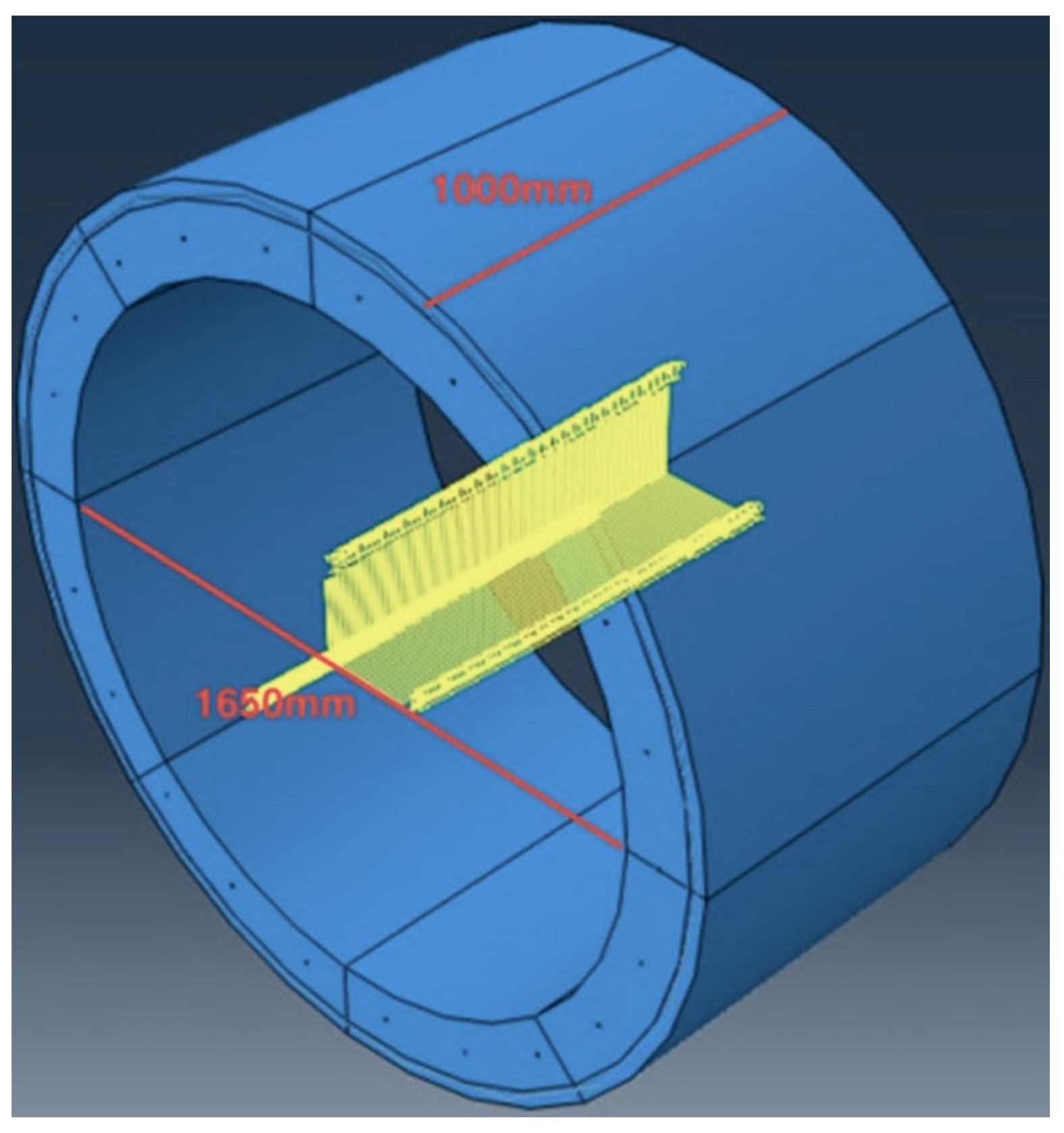
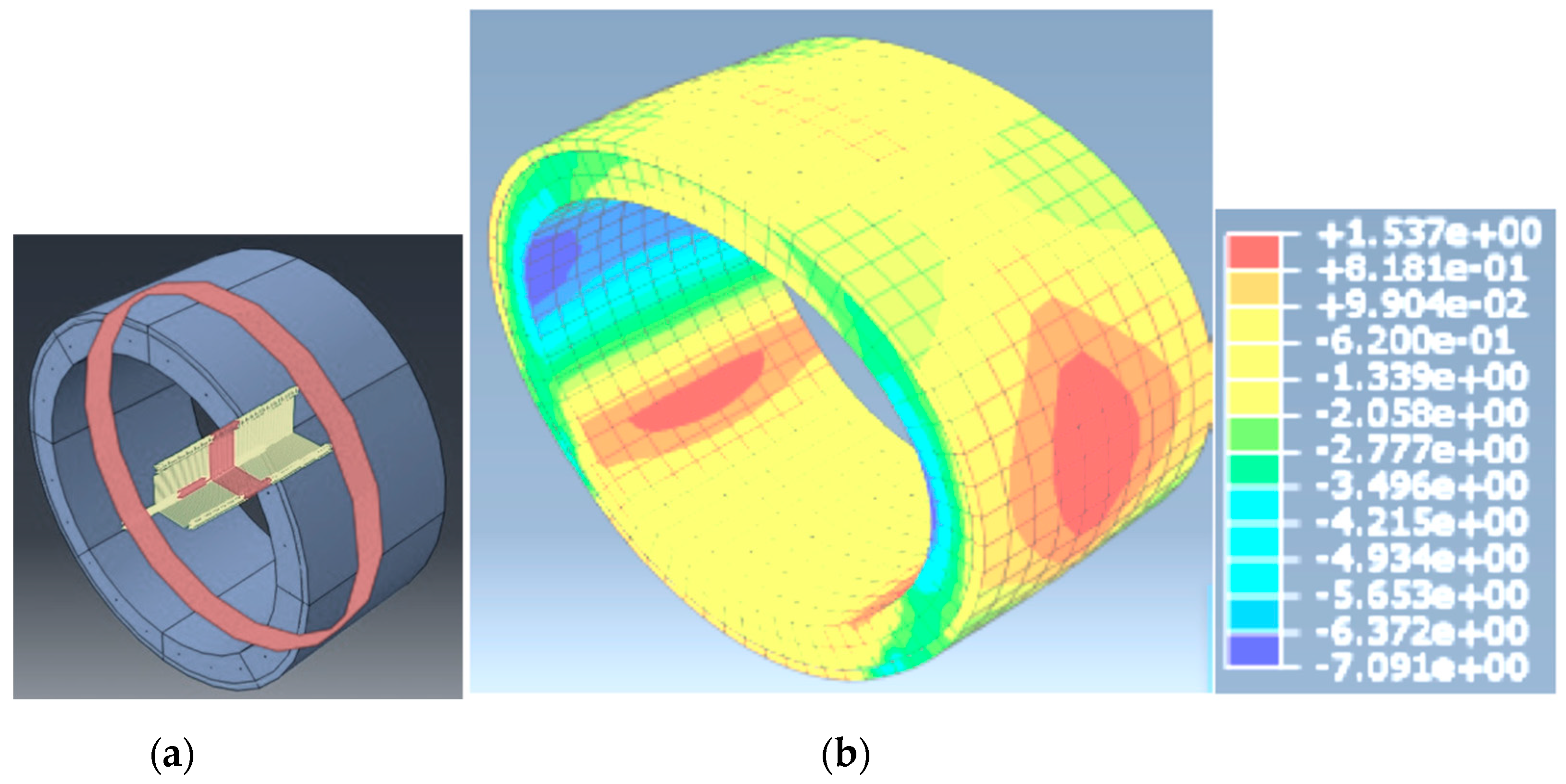
The fourth loading condition simulated a pipe in typical operation mode along with deterioration of the prestressing spiral steel for a region of 200 mm. (total permanent and live loads + 4 atm)
The aforementioned loading conditions were applied both for the non-strengthened and the strengthened models.

3. Results and Discussion: Potential Application of CFRP for Forest Road Pipes

The results presented here are based on loading conditions A to D described above. For all aforementioned scenarios, the external prestress was applied to the spiral strands. The applied prestress was equal to 787 Mpa, below the yielding stress of 1600 Mpa that was measured experimentally. The prestress resulted in a uniform compressive field on top of which the loading conditions A to D were applied. The following results are discussed having as a reference the limit state of the vertical stress s22 along the regions that we mark with the red ellipse in all the following figures. The limit state is developed at the tangential line across the width of the RC pipe. As a result, the tangential s22 is the ultimate stress that can be developed for this double symmetric geometry.
The first loading condition, A, included the self-weight of the pipe, typical loads from the soil above the pipe usually found in forest roads, and the external live load of 80 kN simulating the load of an axle of a truck heavily loaded with timber. For this scenario, the stress distribution along the thickness of the pipe was not uniform, like the distribution of the external prestressing of the strands. The application of dead and live loads resulted in a minimum compressive tangential stress s22 of 5 MPa developed on the outer layer, while the maximum compressive stresses equaled 12 MPa and were developed along the internal layer of the pipe (Figure 6).
For loading case A, in which the pipe was empty and the spiral prestress had no damage, all developed stress components were in compression. Pipes that have been subjected to these forces are structurally robust, and as such, can be re-used in forest road infrastructure.
The second loading condition included all the permanent and live loads with additional application of an internal pressure of 4 atm, simulating water, silt, and forest biomass.
From Figure 7 we see that the worst region where tangential compressive stresses s22 got their minimum and maximum values, are found again at the mid-height of the pipe and more specifically at the outer and inner face, respectively. As a result, the minimum developed stresses s22 became equal to zero (0 MPa) while the developed maximum stresses s22 measured 11.5 MPa and were found in the internal face of the pipe.
The application of an internal pressure simulating water, silt, and forest biomass resulted in the zeroing of the compressive stress, thus reaching the bearing capacity of the prestressed pipe itself. Taking under consideration the aforementioned rationale and the fact that we were using old, in stock pipes in which the spiral prestress had no damages, we could argue that the safety factor of its capacity had not been met.
The third loading condition simulated an extreme scenario of a flood where the demand of the flow inside the prestressed RC pipe would increase to a value of 8 atm. From Figure 8, we observe that the tensile stresses appear at the outer face of the pipe, indicating that we have the initiation of cracks on the concrete surface. At this point we need to emphasize that this scenario included the maximum external prestress of the spiral strands. As a result, the application of this extreme scenario inactivated the compressive field of the pipe, leading to the development of a tensile crack on the outer face of the concrete. In Figure 8, the failure mode is also depicted. Finally, the maximum developed stress s22 was also decreased to a value of 7.5 MPa, which appeared as expected in the internal fiber.
Due to the fact that the present research focuses on the re-use of existing prestressed RC pipes, we felt confident adopting a scenario in which the existed pipe had a damaged area of 200 mm across its width where the spiral strand was corroded. For this region, the external prestress was inactive. As a result, the fourth loading condition, D, was identical to the second loading condition, B, with the additional factor of a deteriorated surface width of 200 mm where the prestress is inactive (see Figure 9a in which the red strands are inactive).
From Figure 9b we observe that the stress distribution along the width is not uniform, whereas stress concentration is observable in the region in which the external prestress does not exist. The developed stresses for this scenario showed great tensile stresses on the outer face equal to 1.55 MPa. Thus, the prestress deactivation of a region of 200 mm, created an unsymmetrical stress field resulting in extreme tensile stresses that could cause small or large cracks, even for the loads of condition B, which is the operating mode.
The following Table 1 summarizes the developed stresses for all loading cases. It is obvious that the application of loading conditions A, B, C, and D convert the compressive uniform stress field of the spiral pretension to a nonuniform field, where for scenarios C and D we observed the development of tensile stresses, and both localized as well as total failure of the pipe due to cracks. For the fourth loading scenario, when we had the prestress deactivation of the 200 mm region, the existed, re-used prestressed RC pipe failed due to the development of “extreme” tensile stresses, which was in accordance with our expectations. Finally, we observed that the maximum compressive stress of 12 Mpa was much less than the average measured maximum of 50 Mpa.
In addition, since our focus was on re-using existing RC pipes, it is realistic to expect several scenarios of pipe deterioration.
For these reasons, our intention was to investigate how the application of externally bonded CFRP sheets onto the outer face of the pipe was going to improve its limit state and increase its structural stability in the four aforementioned loading scenarios.
For the present study, we chose to adopt an extreme scenario to deactivate all prestressed spiral strands. We also chose to apply the strengthening schemes for the extreme flood scenario C. As a result, we implemented two strengthening scenarios. In the first one, we utilized two layers of CFRP, thus we wrapped around the pipe with two layers. In the second scenario, we further increased the strength capacity by attaching four CFRP layers. The adopted limit state of the following scenarios focused on depicting the developed strains onto the CFRP layers. We chose the aforementioned limit state since it was well known from the literature [38] that the ultimate strain capacity of CFRP ranges between 1.2–1.5%. Furthermore, the adhesive between the CFRP layers and mortar was not investigated due to the fact that the CFRP sheets were wrapped around the pipe, resulting in a perfect attachment of the composite, eliminating a debonding failure mode.
Figure 10 and Figure 11 demonstrate the developed vertical strains (ε22) of the pipe with the CFRP layers attached onto it two layers and four layers, respectively. As mentioned before, we deactivated the prestress and applied loading condition C as an extreme scenario. It is depicted that the deformation of the pipe, for both strengthened schemes, was decreased due to the existence of the CFRP sheets. The developed strains onto the two layers of CFRP were equal to 0.6%, resulting in a developed stress on the composite sheet equal to 1400 Mpa. The developed strains on the four layers of CFRP sheets were equal to 0.25%, resulting in ultimate stress values in the range of 650 Mpa.
Finally, we investigated a final scenario in which the loading case C was combined with an additional live load of 32 kN, simulating the external load of a heavy timber truck passing above the strengthened RC pipe. As expected, it was shown that the strengthened RC pipe developed stresses slightly higher than the previous scenario. Table 2 summarizes all aforementioned results. For all cases where the strengthened RC pipes were put to the test, it was shown that the exploitation of the composite material was less than 50%, resulting to increased structural stability for the pipe.
The advancement in knowledge that is yielded through this paper is a direct demonstration of how existed, deteriorated concrete pipes of medium and large radiuses may be subjected to strengthening via CFRP sheets, and as such may be re-used in forest roads as part of road drainage systems. It is clear that the accumulative application of CFRP layers to prestressed concrete pipes not only provided additional structural support to the pipe itself, but it exceeded expectations in doing so by changing the order of magnitude via an extremely cost-effective method. These results beckon the question as to why the reinforcement of prestressed concrete pipes is not more commonplace, particularly in situations where such pipes are frequently exposed to heavy structural loads and high humidity levels.

4. Conclusions

In this paper we have tried to demonstrate a possible solution to a common problem in forest roads: how to structurally strengthen existed, prestressed concrete pipes meant to drain water, which, due to exposure to both high humidity levels and extreme external and internal pressures, suffer structural damage. We conducted a 3D numerical analysis taking measurements of both internal and external pressures and have come to the conclusion that bonding the external face of the pipe with CFRP sheets significantly improves the strength of the pipes, matching the results of Zhai et al. (2020) [31] for prestressed concrete pipes with broken wires using CFRP.
This is demonstrated by the fact that after our prestressed RC pipe was wrapped around with either two or four layers of CFRP sheets, the developed strains of the pipes were decreased for equally applied loads. In the future, we hope to evaluate Lee and Lee’s (2013) [23] method of applying the sheets with double angle attachment in our experimental model. As it is, the coating of prestressed concrete pipes with unidirectional sheets of CFRP seems to be an extremely cost-effective method of providing structural strength for pipelines used in forest roads.

Author Contributions

Conceptualization, R.G. and K.K.; methodology, R.G. and K.K.; software, K.K.; validation, R.G. and K.K.; investigation, R.G. and K.K.; writing—original draft preparation, R.G. and K.K.; writing—review and editing, R.G. and K.K. All authors have read and agreed to the published version of the manuscript.

Funding

No funding was obtained for the dissemination of this project.

Conflicts of Interest

The authors declare no conflict of interest.

References

  1. Picchio, R.; Pignatti, G.; Marchi, E.; Latterini, F.; Benanchi, M.; Foderi, C.; Venanzi, R.; Verani, S. The application of two approaches using GIS technology implementation in forest road network planning in an Italian mountain setting. Forests 2018, 9, 277. [Google Scholar] [CrossRef] [Green Version]
  2. Demir, M. Impacts, management and functional planning criterion of forest road network system in Turkey. Transp. Res. Part A Policy Pr. 2007, 41, 56–68. [Google Scholar] [CrossRef]
  3. Mann, D.; Agrawal, G.; Joshi, P. Spatio-temporal forest cover dynamics along road networks in the Central Himalaya. Ecol. Eng. 2019, 127, 383–393. [Google Scholar] [CrossRef]
  4. Arima, E.Y.; Walker, R.T.; Perz, S.G.; Caldas, M. Loggers and Forest Fragmentation: Behavioral Models of Road Building in the Amazon Basin. Ann. Assoc. Am. Geogr. 2005, 95, 525–541. [Google Scholar] [CrossRef]
  5. Stoeckeler, J.H. Drainage along swamp forest roads lessons from northern Europe. J. For. 1965, 63, 772–776. [Google Scholar]
  6. Enache, A.; Kühmaier, M.; Visser, R.; Stampfer, K. Forestry operations in the European mountains: A study of current practices and efficiency gaps. Scand. J. For. Res. 2016, 31, 412–427. [Google Scholar] [CrossRef]
  7. Karagiannis, K. Forest Roads Part 1; University Printing Services, A.U.Th: Thessaloniki, Greece, 2004. (In Greek) [Google Scholar]
  8. Sun, S.P.; Wang, M. Characteristic of prestressed concrete cylinder pipe. Munic. Eng. Technol. 2006, 24, 121–125. [Google Scholar]
  9. Karagiannis, K.; Eskioglou, P.; Karagiannis, E.; Giannoulas, V.; Kararizos, P.; Doukas, K.; Stergiadou, A. Technical projects and Natural Environment. University Lectures; Tziolas: Thessaloniki, Greece, 2012. [Google Scholar]
  10. Katakalos, K.; Kagioglou, P.; Manos, G. Structural evaluation and proposal of strengthening scheme for a pre-stressed concrete pipe utilizing experimental and numerical techniques. In Proceedings of the COMPDYN 2019, 7th ECCOMAS Thematic Conference on Computational Methods in Structural Dynamics and Earthquake Engineering, Crete, Greece, 24–26 June 2019. [Google Scholar]
  11. Rahman, S.; Smith, G.; Mielke, R.; Keil, B. Rehabilitation of large diameter PCCP: Re-lining and sliplining with steel pipe. In Proceedings of the Pipelines 2012: Innovations in Design, Construction, Operations, and Maintenance, Doing More with Less, Miami Beach, FL, USA, 19–22 August 2012; pp. 494–504. [Google Scholar]
  12. Hu, H.; Dou, T.; Niu, F.; Zhang, H.; Su, W. Experimental and numerical study on CFRP-lined prestressed concrete cylinder pipe under internal pressure. Eng. Struct. 2019, 190, 480–492. [Google Scholar] [CrossRef]
  13. Nor, N.M.; Boestamam, M.H.A.; Yusof, M.A. Carbon fiber reinforced polymer (CFRP) as reinforcement for concrete beam. Int. J. Emerg. Technol. Adv. Eng. 2013, 3, 6–10. [Google Scholar]
  14. Yuan, X.; Zhu, C.; Zheng, W.; Tang, B. Experimental and numerical investigation on carbon fiber-reinforced polymer-strengthened concrete beam after high-temperature action of asphalt paving construction. Adv. Civil Eng. 2019. [Google Scholar] [CrossRef]
  15. Zhang, L.; Sojobi, A.; Liew, K. Sustainable CFRP-reinforced recycled concrete for cleaner eco-friendly construction. J. Clean. Prod. 2019, 233, 56–75. [Google Scholar] [CrossRef]
  16. Altunişik, A.C.; Günaydin, M.; Sevim, B.; Bayraktar, A.; Adanur, S. CFRP composite retrofitting effect on the dynamic characteristics of arch dams. Soil Dyn. Earthq. Eng. 2015, 74, 1–9. [Google Scholar] [CrossRef]
  17. Motavalli, M.; Czaderski, C.; Pfyl-Lang, K. Prestressed CFRP for Strengthening of Reinforced Concrete Structures: Recent Developments at Empa, Switzerland. J. Compos. Constr. 2011, 15, 194–205. [Google Scholar] [CrossRef]
  18. Engindeniz, M.; Ojdrovic, R.P.; Arnold, S.; Jimenez, T. Cure Behavior of Epoxies Used for CFRP Repair of Pipe-lines. In Proceedings of the Pipelines 2014: From Underground to the Forefront of Innovation and Sustainability, Portland, OR, USA, 3–6 August 2014; pp. 908–919. [Google Scholar]
  19. Malvar, L.J.; Cox, J.V.; Cochran, K.B. Bond between Carbon Fiber Reinforced Polymer Bars and Concrete. I: Experimental Study. J. Compos. Constr. 2003, 7, 154–163. [Google Scholar] [CrossRef]
  20. Lee, D.C.; Karbhari, V.M. Rehabilitation of Large Diameter Prestressed Cylinder Concrete Pipe (PCCP) with FRP Composites—Experimental Investigation. Adv. Struct. Eng. 2005, 8, 31–44. [Google Scholar] [CrossRef]
  21. Angus-Hankin, C.; Stokes, B.; Twaddle, A. The transportation of fuelwood from forest to facility. Biomass-Bioenergy 1995, 9, 191–203. [Google Scholar] [CrossRef]
  22. Svenson, G.; Fjeld, D. The impact of road geometry, surface roughness and truck weight on operating speed of logging trucks. Scand. J. For. Res. 2016, 32, 515–527. [Google Scholar] [CrossRef]
  23. Lee, Y.; Lee, E.-T. Retrofit Design of Damaged Prestressed Concrete Cylinder Pipes. Int. J. Concr. Struct. Mater. 2013, 7, 265–271. [Google Scholar] [CrossRef] [Green Version]
  24. Lee, Y.; Lee, E.-T. Analysis of prestressed concrete cylinder pipes with fiber reinforced polymer. KSCE J. Civ. Eng. 2014, 19, 682–688. [Google Scholar] [CrossRef]
  25. Loera, R. PCCP Carbon-Fiber-Liner Repair-Standard-Specifications. In Proceedings of the Pipelines 2006, Chicago, IL, USA, 30 July–2 August 2006; pp. 1–8. [Google Scholar] [CrossRef]
  26. Ge, S.; Sinha, S. Effect of Various Bedding Conditions on Structural Integrity of Prestressed Concrete Cylinder Pipe. J. Mater. Sci. Res. 2014, 4, 34–44. [Google Scholar] [CrossRef]
  27. Moore, I.D.; Selig, E.T.; Haggag, A. Elastic Buckling Strength of Buried Flexible Culverts; Transportation Research Record: Thousand Oaks, CA, USA, 1988; pp. 57–64. [Google Scholar]
  28. Pian, T.; Bucciarelli, L. Buckling of radially constrained circular ring under distributed loading. Int. J. Solids Struct. 1967, 3, 715–730. [Google Scholar] [CrossRef]
  29. Wang, N.; Zarghamee, M.S. LRFD Approach to CFRP Renewal of Prestressed Concrete Cylinder Pipes. In Proceedings of the Pipelines 2012: Innovations in Design, Construction, Operations, and Maintenance, Doing More with Less, Miami Beach, FL, USA, 19–22 August 2012; pp. 481–493. [Google Scholar] [CrossRef]
  30. Alavinasab, A.; Hajali, M.; Castaldi, G.; Burzynski, K. Carbon fiber reinforced polymer liners as a reliable repair method for damaged concrete cylinder pipe. In Proceedings of the Concrete Service Life Extension Conference, Philadelphia, PA, USA, 29 June–1 July 2015; pp. 1–15. [Google Scholar]
  31. Zhai, K.; Fang, H.; Guo, C.; Ni, P.; Fu, B.; Wang, F.; Zhang, C. Strengthening of PCCP with broken wires using pre-stressed CFRP. Constr. Build. Mater. 2021, 267, 120903. [Google Scholar] [CrossRef]
  32. Zarghamee, M.S.; Engindeniz, M. CFRP Renewal of Prestressed Concrete Cylinder Pipe: Part 2. In WRF Web Report; WRF: Alexandria, VA, USA, 2015; p. 4510. [Google Scholar]
  33. Täljsten, B.; Elfgren, L. Strengthening concrete beams for shear using CFRP-materials: Evaluation of different application methods. Comp. Part B Eng. 2000, 31, 87–96. [Google Scholar] [CrossRef]
  34. Degala, S.; Rizzo, P.; Ramanathan, K.; Harries, K.A. Acoustic emission monitoring of CFRP reinforced concrete slabs. Constr. Build. Mater. 2009, 23, 2016–2026. [Google Scholar] [CrossRef]
  35. La Malfa Ribolla, E.; Hajidehi, M.R.; Rizzo, P.; Scimemi, G.F.; Spada, A.; Giambanco, G. Ultrasonic in-spection for the detection of debonding in CFRP-reinforced concrete. Struct. Infrastr. Eng. 2018, 14, 807–816. [Google Scholar] [CrossRef]
  36. Thessaloniki Water Supply & Sewerage Co S.A. (EYATH). Available online: https://www.eyath.gr/?lang=en/sewerage-and-environment-control-lab/?lang=en (accessed on 27 April 2021).
  37. Li, F.; Yuan, Y.; Li, C.-Q. Corrosion propagation of prestressing steel strands in concrete subject to chloride attack. Constr. Build. Mater. 2011, 25, 3878–3885. [Google Scholar] [CrossRef]
  38. Katakalos, K.; Manos, G.; Papakonstantinou, C. Seismic retrofit of R/C T-beams with steel fiber polymers under cyclic loading conditions. Buildings 2019, 9, 101. [Google Scholar] [CrossRef] [Green Version]
Figure 1. (a) In situ drilling of RC pipe. (b) Concrete mechanical properties.
Sustainability 13 04947 g001
Figure 2. (a) Experiment setup. (b) A σ-ε graph depicting the prestressed steel (5 mm, 7 mm).
Sustainability 13 04947 g002
Figure 3. (a) The 75% corroded sample. (b) A σ-ε graph depicting the corroded specimens.
Sustainability 13 04947 g003
Figure 4. The 3D FE model with its basic dimensions.
Sustainability 13 04947 g004
Figure 5. (a) The First loading Condition (permanent + live loads). (b) The second loading condition (permanent + live loads + 4 atm). (c) The third loading condition (permanent + live loads + 8 atm). (d) The fourth loading condition (200 mm deterioration region, permanent + live loads + 4 atm).
Sustainability 13 04947 g005
Figure 6. Developed stresses s22 (MPa) for the first loading condition, A (empty pipe with permanent and live loads).
Sustainability 13 04947 g006
Figure 7. Developed stresses s22 (MPa) for the second loading condition, B (operating mode, internal pressure of 4 atm with permanent and live loads).
Sustainability 13 04947 g007
Figure 8. Developed stresses s22 (MPa) for the third loading condition, C (extreme flood mode, internal pressure of 8 atm with permanent and live loads).
Sustainability 13 04947 g008
Figure 9. (a) Depicting 200 mm deactivation. (b) Developed stresses s22 (MPa) for the fourth loading condition, D (operation mode, pressure of 4 atm with permanent and live loads).
Sustainability 13 04947 g009
Figure 10. Two externally bonded layers of CFRP. Developed stresses s22 (MPa)
Sustainability 13 04947 g010
Figure 11. Four externally bonded layers of CFRP. Developed stresses s22 (MPa)
Sustainability 13 04947 g011
Table 1. Summary of developed stresses for all loading conditions.
Stresses (MPa)
Loading ConditionUniform Spiral Prestress
Inner FaceOuter Face
After pretension−7.70−7.70
A. All external loads−12.0−5.00
B. Operation mode−11.5−0.00
C. Extreme flood demand−7.50+0.33
D. Partial (200 mm) deactivation of prestress−7.09+1.54
Table 2. Summary of developed stresses for strengthened RC pipes.
Stresses (MPa) on CFRP Surface
Loading Condition2 CFRP Layers4 CFRP Layers
Outer FaceOuter Face
Strengthened RC pipes, C loading case1400650
Strengthened RC pipes, Vertical load equals to 32tn1500700
Publisher’s Note: MDPI stays neutral with regard to jurisdictional claims in published maps and institutional affiliations.

