
Design of Decentralized Hybrid Microgrid Integrating Multiple Renewable Energy Sources with Power Quality Improvement


Abstract
:1. Introduction
- Designing a control technique for an interlinking converter for efficient power-sharing among the AC and DC microgrid and power-quality improvement. The proposed control effectively coordinates the power exchange between the AC and DC hybrid microgrid.
- Integration and efficient utilization of renewable energy sources by the superior operation friendliness of the AC and DC microgrids.
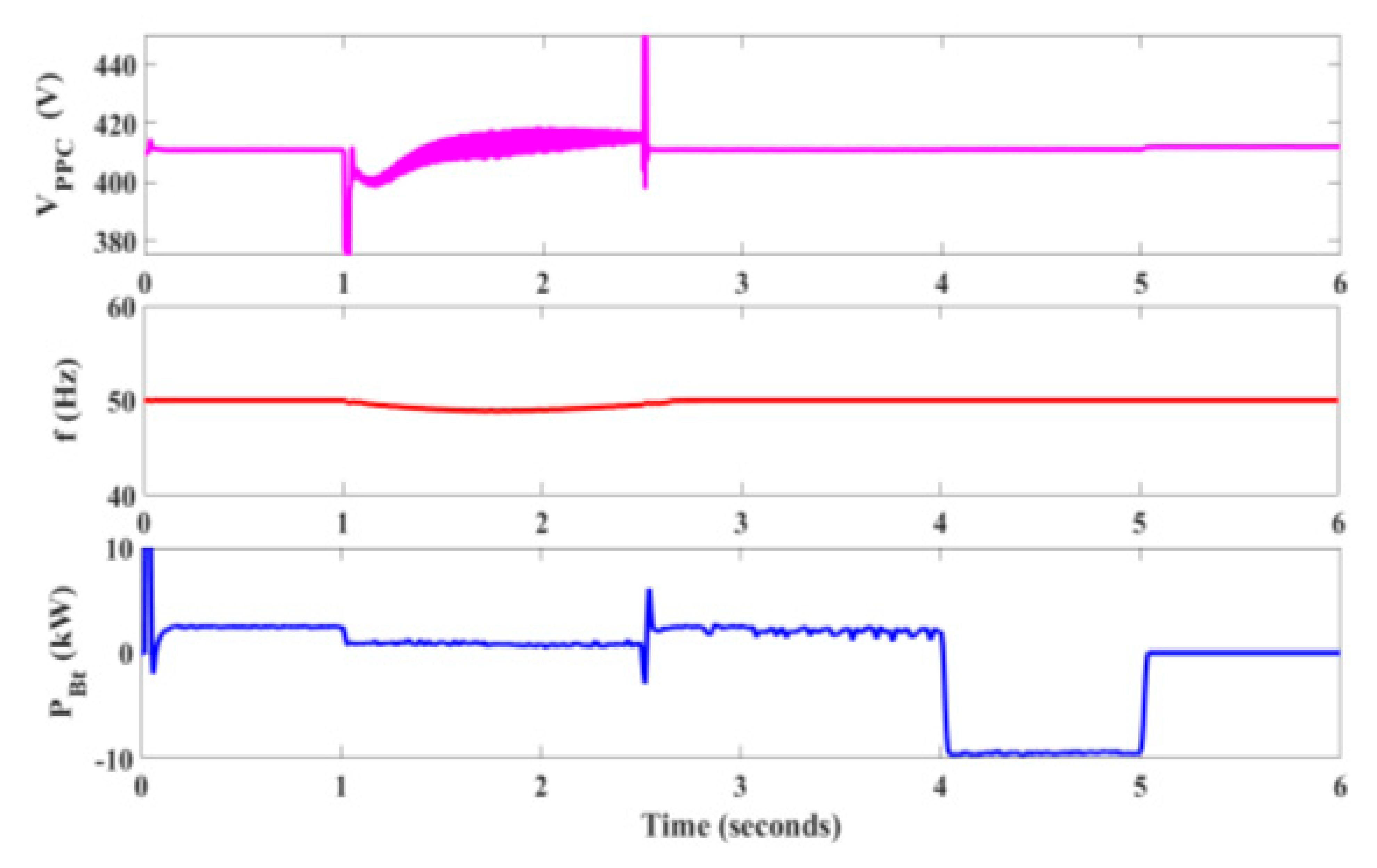
- The proposed control supports the bidirectional power flow between DC and AC microgrids without much deviation in the frequency and a seamless transition between grid-connected and islanded mode with minimal dependence on additional sources.
2. Microgrid Configuration
2.1. Load
2.2. PV Array Design
2.3. Boost Converter Design
2.4. PMSG Wind Turbine
2.5. Fuel Cell
2.6. Inverter
2.7. Buck—Boost Converter
2.8. BESS
2.9. Diesel Generator
2.10. Interlinking Converter
2.11. Utility Grid
3. Control Algorithm
3.1. Solar PV Control
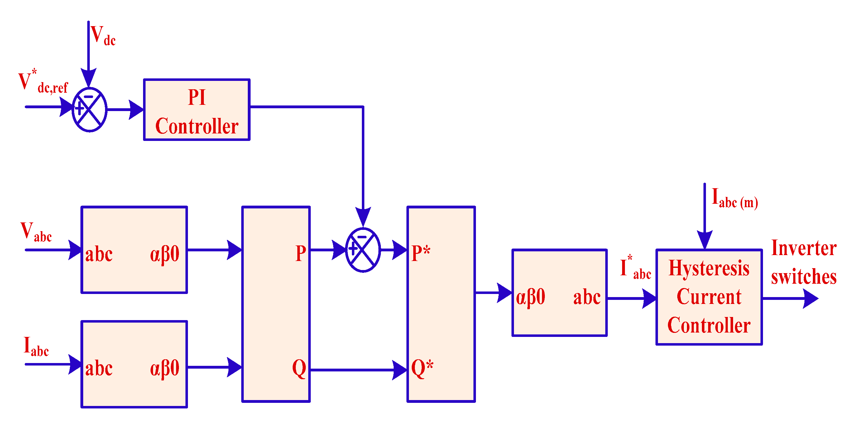
3.2. Inverter Control
3.3. BESS Control
3.4. IC Control
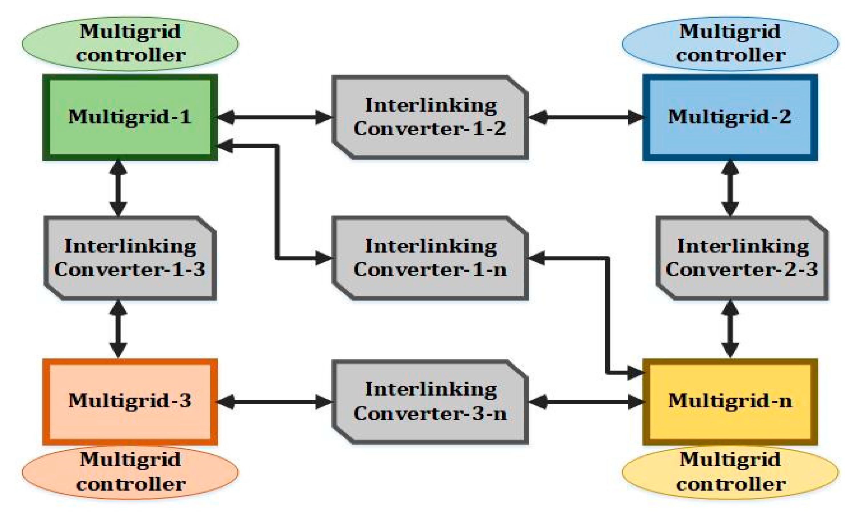
3.5. Control in Multi-Microgrid Approach
4. Simulation Results and Analysis
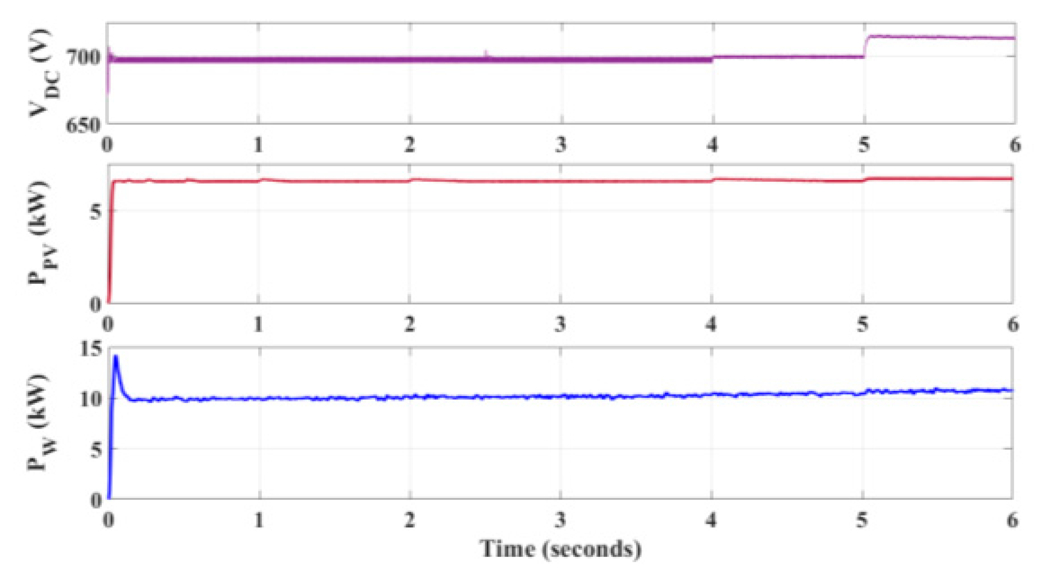
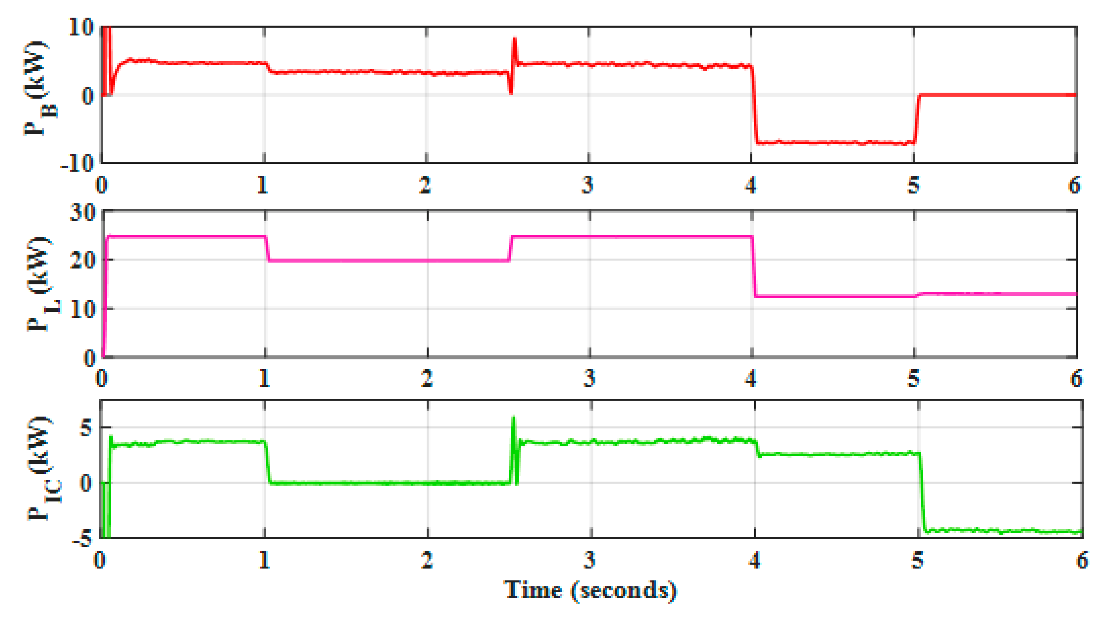
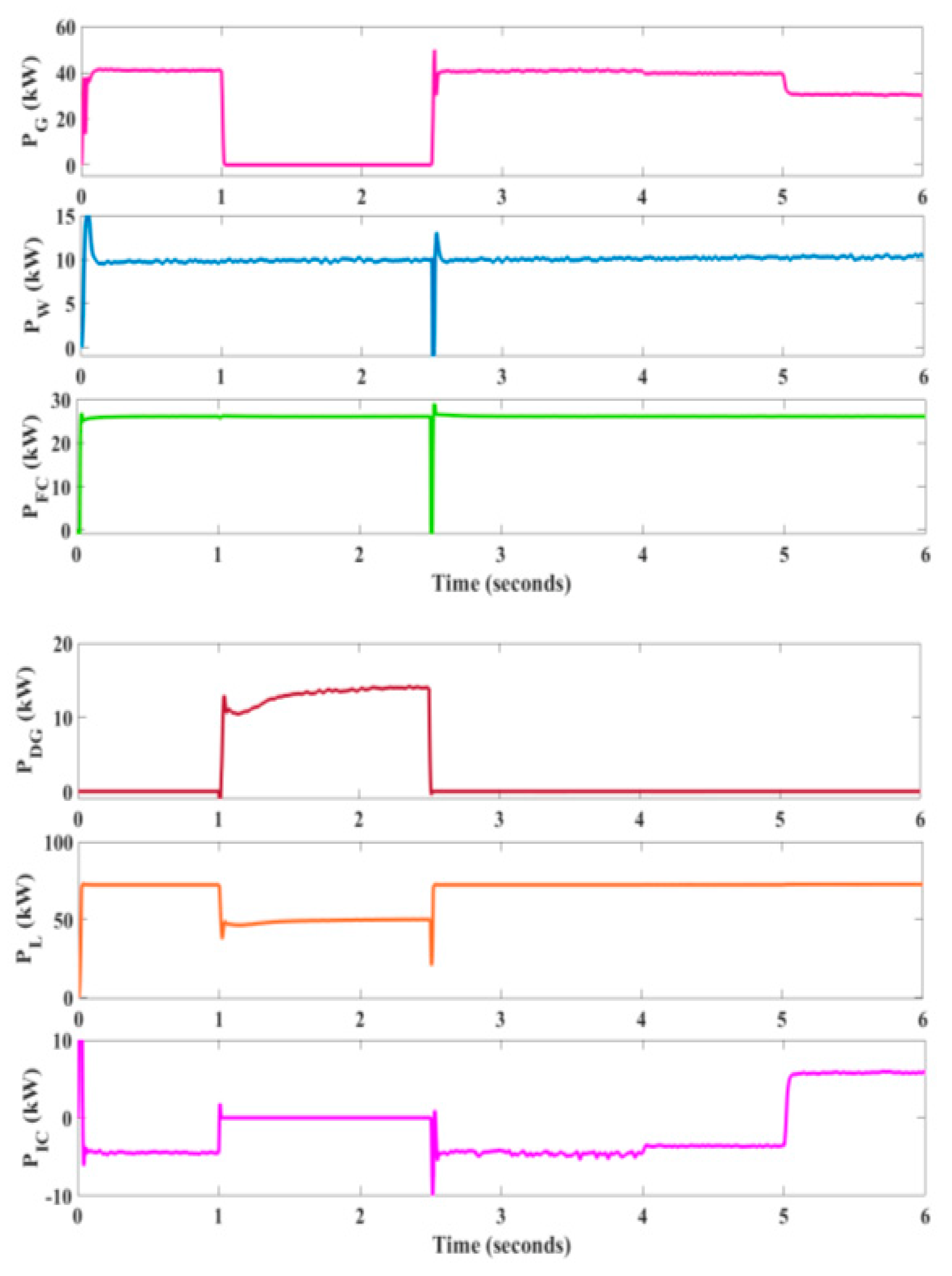
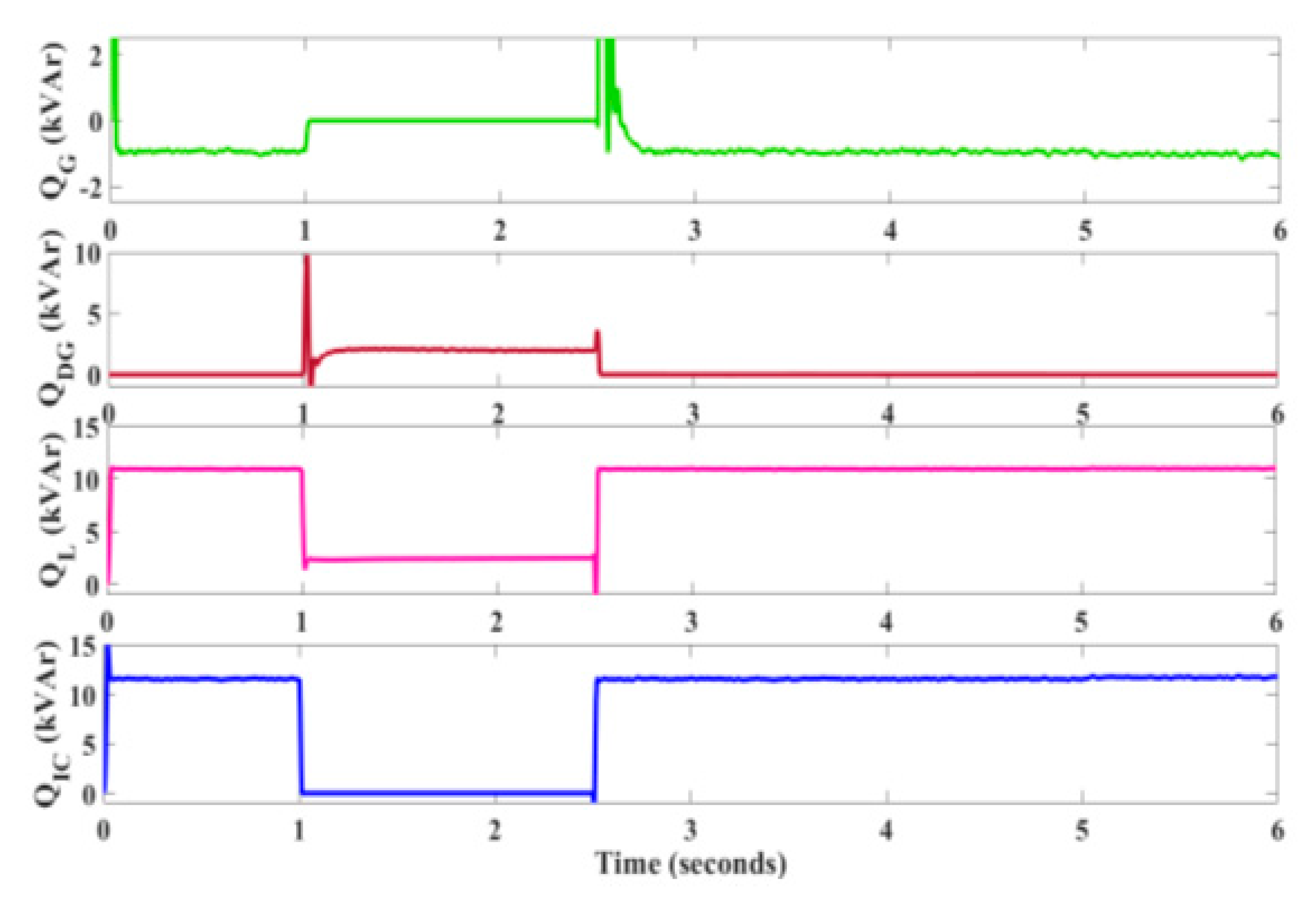
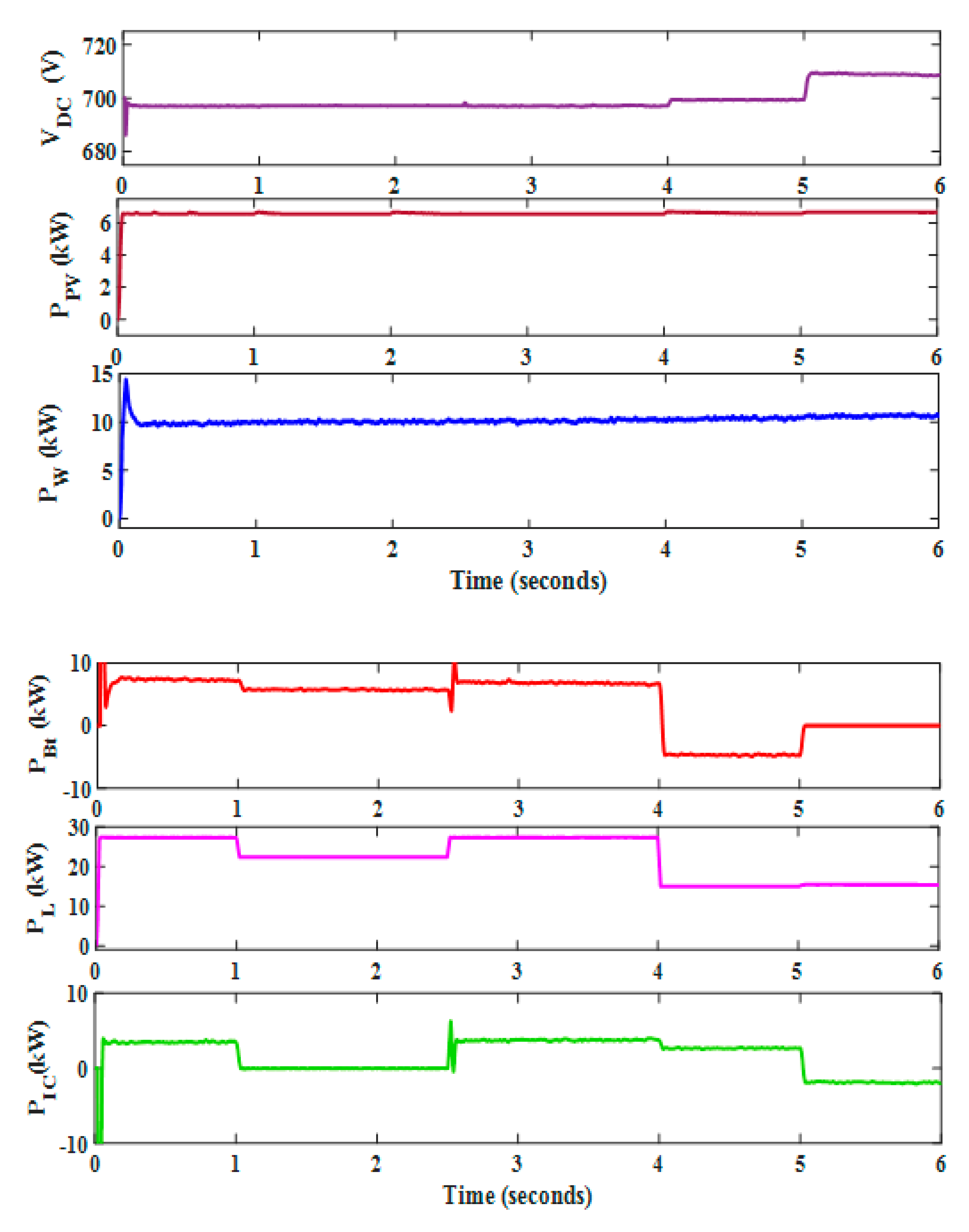
4.1. Mode 1: Grid-Connected Mode
4.2. Mode 2: Islanded Mode
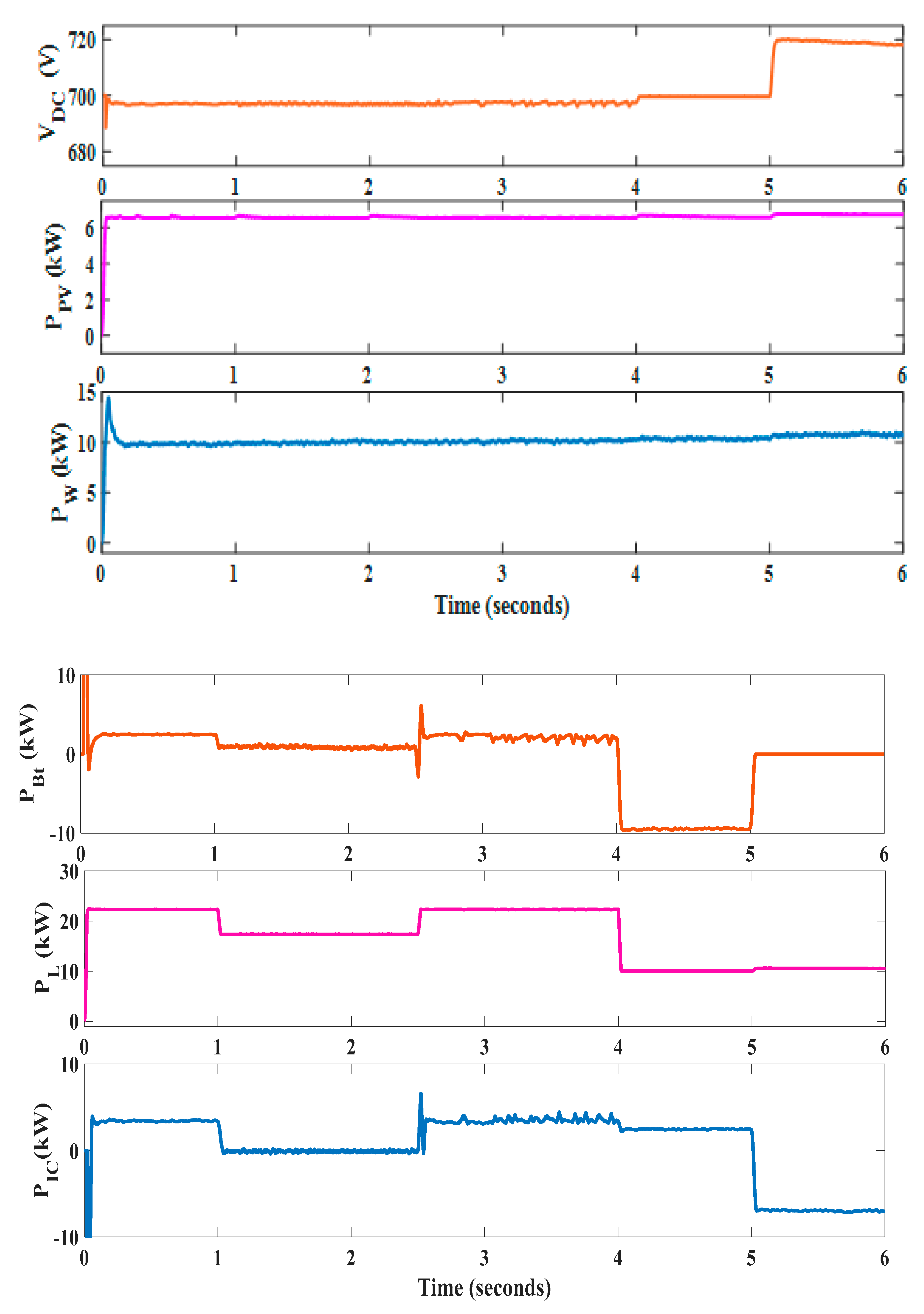
4.3. Mode 3: Battery-Charging Mode
4.4. Mode 4: DC-to-AC Power Flow
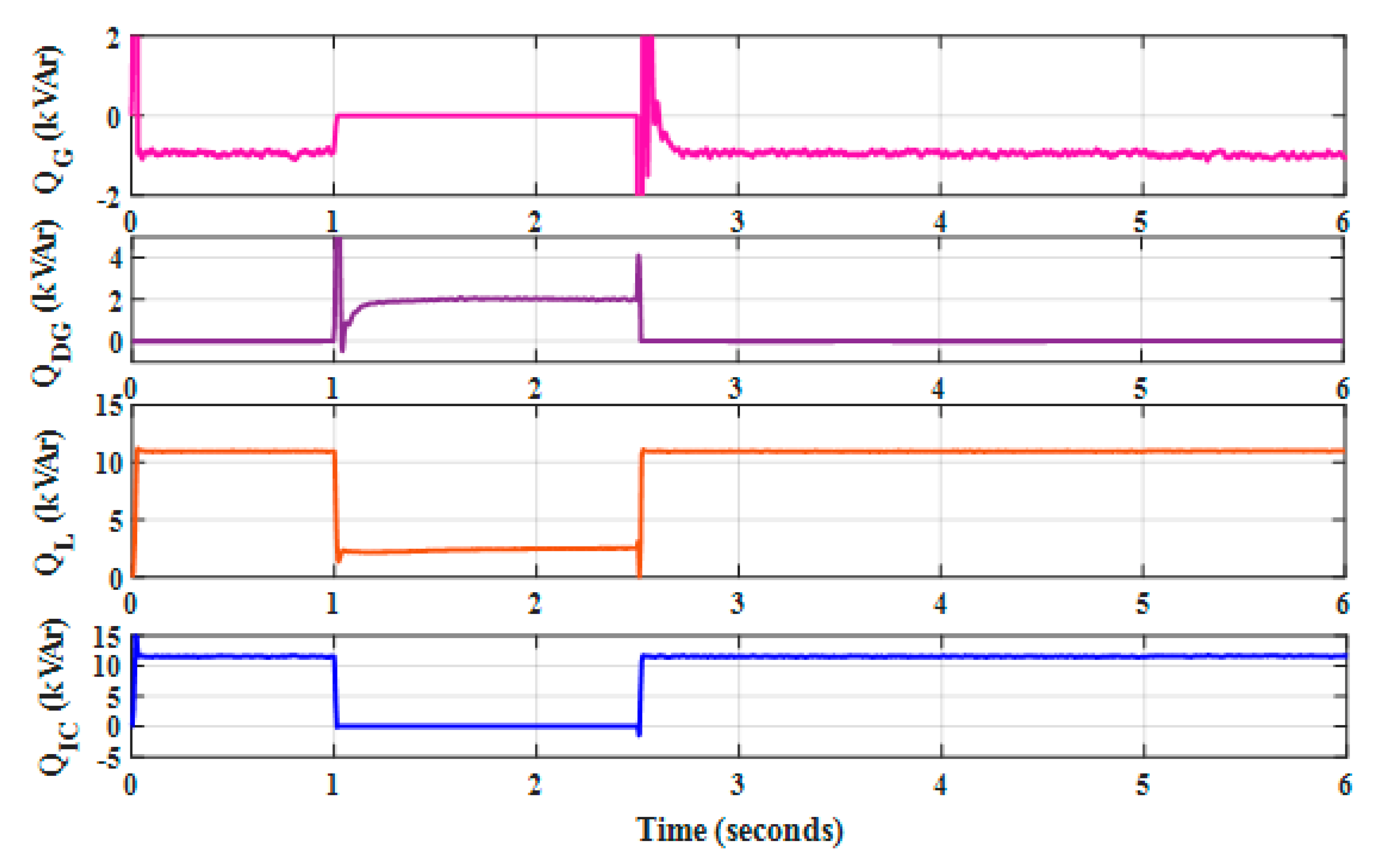
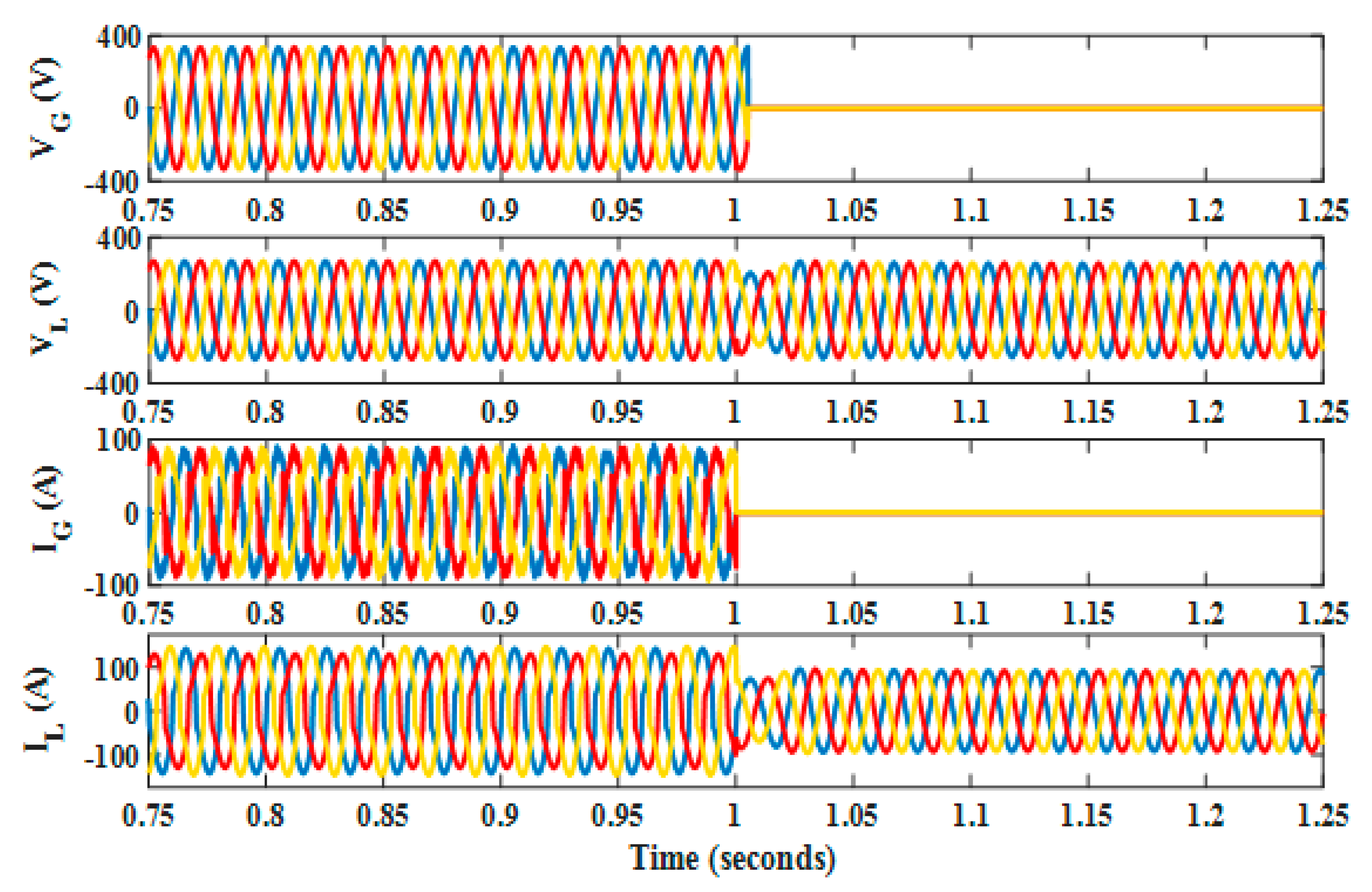
4.5. Virtual APF
4.6. Performance of HMG with a Reduction in Load
4.7. Performance of HMG with Increment in Load
5. Conclusions
- The proposed controller efficiently coordinates the AC/DC hybrid microgrid in all four modes of operation.
- The required power is transferred between the AC and DC microgrid via the interlinking converter. With an energy-storage system, the power exchange between the microgrids is efficiently managed by the controller and only the excess power demand is obtained from the utility grid.
- The modified control technique for the interlinking converter improves the power quality under unbalanced and non-linear load conditions.
- The interlinking converter supports AC/DC voltage bidirectionally during the islanded mode of operation. This reduces the need for additional voltage sources.
- The proposed controller helps in the seamless transfer between grid-connected and isolated modes.
- The future works to be carried out are:
- The proposed controller can be extended to a multi-microgrid approach.
- The multi-parallel interlinking converter can be utilized in place of the interlinking converter, and an analysis can be carried out.
- The proposed controller can be applied for real-time applications.
- Economic analysis and the impact of the proposed microgrid on the present microgrid setup can be analyzed through HOMER software.
- Degradation of the hybrid components can be included in the analysis.
Author Contributions
Funding
Institutional Review Board Statement
Informed Consent Statement
Data Availability Statement
Acknowledgments
Conflicts of Interest
Abbreviations
| APF | Active power filter |
| BESS | Battery energy storage system |
| DG | Distributed generation |
| HMG | Hybrid microgrid |
| IC | Interlinking converter |
| IRPT | Instantaneous reactive power theory |
| MG | Microgrid |
| MGCC | Microgrid centralized controller |
| MPPT | Maximum power point tracking |
| PCC | Point of common coupling |
| PI | Proportional integral |
| PLL | Phase locked loop |
| PMSG | Permanent magnet synchronous generator |
| P&O | Perturb and observe |
| RES | Renewable energy sources |
| STS | Static transfer switch |
| THD | Total harmonic distortion |
| WT | Wind turbine |
Appendix A

| Utility Grid | |
| Three-phase four-wire system with balanced voltages | 415 V, 50 Hz |
| Source impedance | R = 1 Ω, L= 6 mH |
| PMSG Wind Turbine | |
| Nominal mechanical power—Pm | 12 kW |
| Nominal generator electrical power—Pg | 12/0.9 kVA |
| Nominal wind speed—Vm | 12 m/s |
| Maximum power at base speed | 0.8 (p.u) |
| Wind Turbine Inverter | |
| DC link voltage—VDC | 677.49~700 V |
| DC link capacitor—CDC | 4685 μF~4700 μF |
| Coupling inductor—(R + L) | 0.026 + 8.22 mH |
| Ripple filter—(P + Q) | 20 W + 1 kVAr |
| Fuel Cell | |
| Voltage at (0 A, 1 A) | (450.442.5) V |
| Nominal current—Inom | 40 A |
| Nominal voltage—Vnom | 350 V |
| Maximum current—Iend | 140 A |
| Power obtained—Pobt | 27 kW |
| Boost Converter | |
| Inductor—L | 3.9 mH |
| Capacitor—C | 70 µF |
| Switching frequency—fs | 10 kHz |
| Duty cycle—D | 50% |
| Buck–Boost Converter | |
| Inductor—L | 3 mH |
| Capacitor—C | 70 µF |
| Switching frequency—fs | 10 kHz |
| Duty cycle—D | 50% |
| Fuel Cell Inverter | |
| DC link voltage—VDC | 677.49~700 V |
| DC link capacitor—CDC | 4685~4700 µF |
| Coupling inductor—(R + L) | 0.01722 + 5.48 mH |
| Ripple filter—(P + Q) | 30 W + 1.5 kVAr |
References
- Amirthalingam, M. A Novel Technology utilizing Renewable energies to mitigate air pollution, global warming & climate change. In Proceedings of the 1st International Conference on the Developments in Renewable Energy Technology (ICDRET), Dhaka, Bangladesh, 17–19 December 2009; pp. 1–3. [Google Scholar]
- Bauer, N.; Mouratiadou, I.; Luderer, G.; Baumstark, L.; Brecha, R.J.; Edenhofer, O.; Kriegler, E. Global fossil energy markets and climate change mitigation—An analysis with REMIND. Clim. Chang. 2016, 136, 69–82. [Google Scholar] [CrossRef]
- Tiwari, S.K.; Singh, B.; Goel, P.K. Design and control of micro-grid fed by renewable energy generating sources. IEEE Trans. Ind. Appl. 2018, 54, 2041–2050. [Google Scholar] [CrossRef]
- Bose, B.K. Global Energy Scenario and Impact of Power Electronics in 21st Century. IEEE Trans. Ind. Electron. 2013, 60, 2638–2651. [Google Scholar] [CrossRef]
- Singh, B.; Pathak, G.; Panigrahi, B.K. Seamless Transfer of Renewable-Based Microgrid between Utility Grid and Diesel Generator. IEEE Trans. Power Electron. 2018, 33, 8427–8437. [Google Scholar] [CrossRef]
- Ochs, D.S.; Mirafzal, B.; Sotoodeh, P. A Method of Seamless Transitions Between Grid-Tied and Stand-Alone Modes of Operation for Utility-Interactive Three-Phase Inverters. IEEE Trans. Ind. Appl. 2014, 50, 1934–1941. [Google Scholar] [CrossRef]
- Tang, F.; Guerrero, J.M.; Vasquez, J.C.; Wu, D.; Meng, L. Distributed Active Synchronization Strategy for Microgrid Seamless Reconnection to the Grid Under Unbalance and Harmonic Distortion. IEEE Trans. Smart Grid 2015, 6, 2757–2769. [Google Scholar] [CrossRef] [Green Version]
- Olivares, D.E.; Mehrizi-Sani, A.; Etemadi, A.H.; Cañizares, C.A.; Iravani, R.; Kazerani, M.; Hajimiragha, A.H.; Gomis-Bellmunt, O.; Saeedifard, M.; Palma-Behnke, R.; et al. Trends in Microgrid Control. IEEE Trans. Smart Grid 2014, 5, 1905–1919. [Google Scholar] [CrossRef]
- Fathima, H.; Prabaharan, N.; Palanisamy, K.; Kalam, A.; Mekhilef, S.; Justo, J.J. Hybrid-Renewable Energy Systems in Microgrids: Integration, Developments and Control; Woodhead Publishing: Thorston, UK, 2018. [Google Scholar]
- Pannala, S.; Patari, N.; Srivastava, A.K.; Padhy, N.P. Effective Control and Management Scheme for Isolated and Grid Connected DC Microgrid. IEEE Trans. Ind. Appl. 2020, 56, 6767–6780. [Google Scholar] [CrossRef]
- Rezkallah, M.; Chandra, A.; Singh, B.; Singh, S. Microgrid: Configurations, Control and Applications. IEEE Trans. Smart Grid 2019, 10, 1290–1302. [Google Scholar] [CrossRef]
- Liu, X.; Wang, P.; Loh, P.C. A Hybrid AC/DC Microgrid and Its Coordination Control. IEEE Trans. Smart Grid 2011, 2, 278–286. [Google Scholar]
- Li, H.; Li, Y.; Guerrero, J.M.; Cao, Y. AComprehensive Inertial Control Strategy for Hybrid AC/DC Microgrid with Distributed Generations. IEEE Trans. Smart Grid 2020, 11, 1737–1747. [Google Scholar]
- Zolfaghari, M.; Gharehpetian, G.B.; Shafie-khan, M.; Catalao, J.P.S. Comprehensive review on the strategies for controlling the interconnection of AC and DC microgrids. Int. J. Electr. Power Energy Syst. 2021, 136, 107742. [Google Scholar] [CrossRef]
- Wang, L.; Fu, X.; Wong, M. Operation and Control of a Hybrid Coupled Interlinking Converter for Hybrid AC/Low Voltage DC Microgrids. IEEE Trans. Ind. Electron. 2021, 68, 7104–7114. [Google Scholar] [CrossRef]
- Phan, D.; Lee, H. Interlinking Converter to Improve Power Quality in Hybrid AC–DC Microgrids With Nonlinear Loads. IEEE J. Emerg. Sel. Top. Power Electron. 2019, 7, 1959–1968. [Google Scholar] [CrossRef]
- Hussain, M.N.; Melath, G.; Agarwal, V. An Active Damping Technique for PI and Predictive Controllers of an Interlinking Converter in an Islanded Hybrid Microgrid. IEEE Trans. Power Electron. 2021, 36, 5521–5529. [Google Scholar] [CrossRef]
- Shoeb, M.A.; Shahnia, F.; Shafiullah, G.M. A Multilayer and Event-Triggered Voltage and Frequency Management Technique for Microgrid’s Central Controller Considering Operational and Sustainability Aspects. IEEE Trans. Smart Grid 2019, 10, 5136–5151. [Google Scholar] [CrossRef]
- Jha, S.; Hussain, I.; Singh, B.; Mishra, S. Optimal operation of PV-DG-battery based microgrid with power quality conditioner. IET Renew. Power Gener. 2019, 13, 418–426. [Google Scholar] [CrossRef]
- Jayachandran, J.; Sachithanandam, R.M. Neural network-based control algorithm for DSTATCOM under non-ideal source voltage and varying load conditions. Can. J. Electr. Comput. Eng. 2015, 38, 307–317. [Google Scholar] [CrossRef]
- Brandao, D.I.; Santos, R.P.d.; Silva, W.W.A.G.; Oliveira, T.R.; Donoso-Garcia, P.F. Model-Free Energy Management System for Hybrid Alternating Current/Direct Current Microgrids. IEEE Trans. Ind. Electron. 2021, 68, 3982–3991. [Google Scholar] [CrossRef]
- IEEE Recommended Practice and Requirements for Harmonic Control in Electric Power Systems. In IEEE Std 519-2014 (Revision of IEEE Std 519-1992); IEEE: Piscataway, NJ, USA, 11 June 2014; pp. 1–29.
- Jayachandran, J.; Sachithanandam, R.M. Performance investigation of artificial intelligence-based controller for three-phase four-leg shunt active filter. Front. Energy 2015, 9, 446–460. [Google Scholar] [CrossRef]
- Malathi, S.; Jayachandran, J. FPGA Implementation of NN based LMS-LMF Control Algorithm in DSTATCOM for Power Quality Improvement. Control. Eng. Pract. 2020, 98, 104378. [Google Scholar] [CrossRef]
- Kaur, S.; Dwivedi, B. Power quality issues and their mitigation techniques in microgrid system-a review. In Proceedings of the 7th India International Conference on Power Electronics (IICPE), Patiala, India, 17–19 November 2016; pp. 1–4. [Google Scholar]
- Chang, J.-W.; Lee, G.-S.; Moon, S.-I.; Hwang, P.-I. A Novel Distributed Control Method for Interlinking Converters in an Islanded Hybrid AC/DC Microgrid. IEEE Trans. Smart Grid 2021, 12, 3765–3779. [Google Scholar] [CrossRef]
- Bhim, S.; Chandra, A.; Al-Haddad, K. Power Quality: Problems and Mitigation Techniques; John Wiley & Sons: Hoboken, NJ, USA, 2014. [Google Scholar]
- Malathi, S.; Sachithanandam, R.M.; Jayachandran, J. Performance comparison of neural network based multi output SMPS with improved power quality and voltage regulation. Control Eng. Appl. Inform. 2018, 20, 86–97. [Google Scholar]
- Khederzadeh, M.; Sadeghi, M. Virtual active power filter: A notable feature for hybrid ac/dc microgrids. IET Gener. Transm. Distrib. 2016, 10, 3539–3546. [Google Scholar] [CrossRef]
- Shafiullah, G.M.; Oo, A.M.T.; Ali, A.B.M.S.; Jarvis, D.; Wolfs, P. Economic Analysis of Hybrid Renewable Model for Subtropical Climate. Int. J. Therm. Environ. Eng. 2010, 1, 57–65. [Google Scholar] [CrossRef] [Green Version]
- Shafiullah, G.M.; Arif, M.T.; Oo, A.M.T. Mitigation strategies to minimize potential technical challenges of renewable energy integration. Sustain. Energy Technol. Assess. 2018, 25, 24–42. [Google Scholar] [CrossRef]
- Khomsi, C.; Bouzid, M.; Champenois, G.; Jelassi, K. Improvement of the Power Quality in Single Phase Grid Connected Photovoltaic System Supplying Nonlinear Load. In Advanced Technologies for Solar Photovoltaics Energy Systems; Motahhir, S., Eltamaly, A.M., Eds.; Green Energy and Technology; Springer: Cham, Switzerland, 2021. [Google Scholar] [CrossRef]
- Eltamaly, A.M. A novel musical chairs algorithm applied for MPPT of PV systems. Renew. Sustain. Energy Rev. 2021, 146, 111135. [Google Scholar] [CrossRef]
- Liu, Q.; Caldognetto, T.; Buso, S. Flexible control of interlinking converters for DC microgrids coupled to smart AC power systems. IEEE Trans. Ind. Electron. 2019, 66, 3477–3485. [Google Scholar] [CrossRef]
- Wang, J.; Jin, C.; Wang, P. A uniform control strategy for the inter-linking converter in hierarchical controlled hybrid AC/DC microgrids. IEEE Trans. Ind. Electron. 2018, 65, 6188–6197. [Google Scholar] [CrossRef]
- Li, X.; Li, Y.; Guo, Z.; Hong, C.; Zhang, Y.; Wang, C. A unified control for the DC-AC interlinking converters in hybrid AC/DC microgrids. IEEE Trans. Smart Grid 2018, 9, 6540–6553. [Google Scholar] [CrossRef]
- Yang, P.; Xia, Y.; Yu, M.; Wei, W.; Peng, Y. A decentralized coordination control method for parallel bidirectional power converters in a hybrid AC-DC microgrid. IEEE Trans. Ind. Electron. 2018, 65, 6217–6228. [Google Scholar] [CrossRef]
- Xia, Y.; Peng, Y.; Yang, P.; Wei, W. Distributed coordination control for multiple bidirectional power converters in a hybrid AC/DC microgrid. IEEE Trans. Power Electron. 2017, 32, 4949–4959. [Google Scholar] [CrossRef]
- Heier, S. Grid Integration of Wind Energy Conversion Systems; Wiley: Hoboken, NJ, USA, 2006. [Google Scholar]
- Valverde, L.; Bordons, C.; Rosa, F. Integration of Fuel Cell Technologies in Renewable -Energy-Based Microgrids Optimizing Operational Costs and Durability. IEEE Trans. Ind. Appl. 2016, 63, 167–177. [Google Scholar] [CrossRef]
- Ucar, M.; Ozdemir, E. Control of a 3-phase 4-leg active power filter under non-ideal mains voltage condition. Electr. Power Syst. Res. 2008, 78, 58–73. [Google Scholar] [CrossRef]
- Villanueva-Rosario, J.A.; Santos-Garcia, F.; Aybar-Mejia, M.E.; Mendoza-Araya, P.; Molina-García, A. Coordinated ancillary services, market participation and communication of multi-microgrids: A review. Appl. Energy 2022, 308, 118332. [Google Scholar] [CrossRef]


| Control Strategies | ||||||
|---|---|---|---|---|---|---|
| Conditions | Proposed | Ref. [34] | Ref. [35] | Ref. [36] | Ref. [37] | Ref. [38] |
| Support of DC voltage | yes | No | yes | yes | No | yes |
| Support of AC voltage | yes | yes | yes | yes | yes | No |
| Frequency deviation | yes | No | No | No | No | No |
| Continuous operation of voltage sources | No | yes | yes | yes | yes | yes |
| Implementation to parallel interlinking converter | yes | No | No | yes | yes | yes |
| Seamless operation between grids | yes | No | No | No | No | No |
| Power-quality Improvement | yes | No | yes | No | No | No |
| Solar PV Array | |
|---|---|
| Model | SunPower SPR—305WHT |
| Number of cells—Nc | 96 |
| Open-circuit voltage—Voc | 64.2 V |
| Short-circuit current—Isc | 5.96 A |
| Voltage at maximum power point—VMP | 54.7 V |
| Current at maximum power point—IMP | 5.58 A |
| No. of series modules per string—NS | 6 |
| No. of parallel strings—NP | 4 |
| Maximum power extractable—Po | 7 kW |
| Sl. No. | Mode | Time Interval in Seconds | Description |
|---|---|---|---|
| 1 | Mode 1: grid-connected mode | 0 to 1 s and 2.5 s to 4 s | AC DG units are synchronized with grid voltage and frequency (three-phase four-wire balanced system—415 V, 50 Hz) |
| 2 | Mode 2: islanded mode | 1 s to 2.5 s | The system is isolated from the utility grid. The diesel generator acts as the voltage and frequency reference in the AC sub-grid. Non-critical loads of DC and AC sub-grids are turned off. |
| 3 | Mode 3: battery-charging mode | 4 s to 5 s | The load in the DC sub-grid is lesser than the DG unit’s generation and the battery gets charged. |
| 4 | Mode 4: DC-o-AC power-flow mode | 5 s to 6 s | Power transfer takes place from the DC to the AC sub-grid. The battery is presumed to be fully charged. |
| Mode | Details of Load Connected | PPV* (kW) | PWT-DC* (kW) | PB* (kW) | PIC* (kW) | PWT-AC* (kW) | PFC* (kW) | PG* (kW) | PDG* (kW) |
|---|---|---|---|---|---|---|---|---|---|
| Mode 1 | DC sub grid load—25 kW | 6.6 | 10 | 4.6 | 3.8 | - | - | - | |
| Non-linear loads in AC sub grid—P = 72.5 kW | - | - | - | −3.8 | 10 | 26 | 40.3 | - | |
| Non-linear loads in AC sub-grid—Q = 11 kVAr | - | - | - | 12 | - | - | - | −1 | |
| Mode 2 | DC sub-grid critical load—20 kW | 6.6 | 10 | 3.4 | - | - | - | - | - |
| Non-linear critical loads in AC sub-grid—P = 50 kW | - | - | - | - | 10 | 26 | - | 14 | |
| Non-linear critical loads in AC sub-grid—Q = 2.5 kVAr | - | - | - | - | - | - | - | 2.5 | |
| Mode 3 | DC sub-grid load—12.5 kW | 6.6 | 10 | −7 | 2.9 | - | - | - | |
| Non-linear loads in AC sub-grid—P = 72.5 kW | - | - | - | −2.9 | 10 | 26 | 39.4 | - | |
| Mode 4 | DC sub-grid load—12.5 kW | 6.6 | 10 | - | −4.1 | - | - | - | - |
| Non-linear loads in AC sub-grid—P = 72.5 kW | 4.1 | 10 | 26 | 32.4 | - |
| Phase | IC as APF in HMG | IC for Power Exchange in HMG | ||||
|---|---|---|---|---|---|---|
| AC Sub-Grid Voltage | Grid Current | Load Current | AC Sub-Grid Voltage | Grid Current | Load Current | |
| %THD | %THD | %THD | %THD | %THD | %THD | |
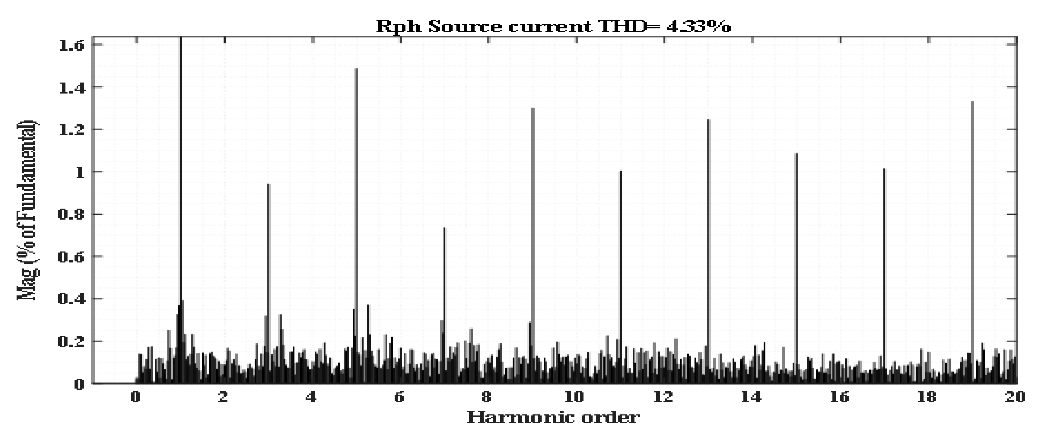
| Rph | 0.07 | 4.33 | 14.29 | 7.50% | 15.4 | 14.29 |
| Yph | 0.07 | 4.64 | 15.77 | 8.30% | 16.2 | 15.77 |
| Bph | 0.07 | 4.24 | 13.29 | 8.50% | 15.9 | 13.29 |
| Mode | Details of Load Connected | PPV* (kW) | PWT-DC* (kW) | PB* (kW) | PIC* (kW) | PWT-AC* (kW) | PFC* (kW) | PG* (kW) | PDG* (kW) |
|---|---|---|---|---|---|---|---|---|---|
| Mode 1 | DC sub-grid load—22.5 kW | 6.6 | 10 | 2.5 | 3.4 | - | - | - | |
| Non-linear loads in AC sub grid—P = 72.5 kW | - | - | - | −3.4 | 10 | 26 | 40 | - | |
| Non-linear loads in AC sub grid—Q = 11 kVAr | 12 | −1 | |||||||
| Mode 2 | DC sub-grid critical load—18 kW | 6.6 | 10 | 1.4 | - | - | - | - | - |
| Non-linear critical loads in AC sub-grid—P = 50 kW | - | - | - | - | 10 | 26 | - | 14 | |
| Non-linear critical loads in AC sub-grid—Q = 2.5 kVAr | - | - | - | - | - | - | - | 2.5 | |
| Mode 3 | DC sub-grid load—10 kW | 6.6 | 10 | −9 | 2.4 | - | - | - | |
| Non-linear loads in AC sub grid—P = 72.5 kW | - | - | - | −2.4 | 10 | 26 | 38.9 | - | |
| Mode 4 | DC sub-grid load—11 kW | 6.6 | 10 | - | −5.6 | - | - | - | - |
| Non-linear loads in AC sub-grid—P = 72.5 kW | 5.6 | 10 | 26 | 30.9 | - |
| Mode | Details of Load Connected | PPV* (kW) | PWT-DC* (kW) | PB* (kW) | PIC* (kW) | PWT-AC* (kW) | PFC* (kW) | PG* (kW) | PDG* (kW) |
|---|---|---|---|---|---|---|---|---|---|
| Mode 1 | DC sub-grid load—27.5 kW | 6.6 | 10 | 7.1 | 3.8 | - | - | - | |
| Non-linear loads in AC sub-grid—P = 72.5 kW | - | - | - | −3.8 | 10 | 26 | 40.3 | - | |
| Non-linear loads in AC sub-grid—Q = 11 kVAr | 12 | −1 | |||||||
| Mode 2 | DC sub-grid critical load—22 kW | 6.6 | 10 | 5.4 | - | - | - | - | - |
| Non-linear critical loads in AC sub-grid—P = 50 kW | - | - | - | - | 10 | 26 | - | 14 | |
| Non-linear critical loads in AC sub-grid—Q = 2.5 kVAr | - | - | - | - | - | - | - | 2.5 | |
| Mode 3 | DC sub-grid load- 12.5 kW | 6.6 | 10 | −7 | 2.9 | - | - | - | |
| Non-linear loads in AC sub-grid—P = 72.5 kW | - | - | - | −2.9 | 10 | 26 | 39.4 | - | |
| Mode 4 | DC sub-grid load—12.5 kW | 6.6 | 10 | - | −4.1 | - | - | - | - |
| Non-linear loads in AC sub-grid—P = 72.5 kW | 4.1 | 10 | 26 | 32.4 | - |
Publisher’s Note: MDPI stays neutral with regard to jurisdictional claims in published maps and institutional affiliations. |
© 2022 by the authors. Licensee MDPI, Basel, Switzerland. This article is an open access article distributed under the terms and conditions of the Creative Commons Attribution (CC BY) license (https://creativecommons.org/licenses/by/4.0/).
Share and Cite
Jayaram, J.; Srinivasan, M.; Prabaharan, N.; Senjyu, T. Design of Decentralized Hybrid Microgrid Integrating Multiple Renewable Energy Sources with Power Quality Improvement. Sustainability 2022, 14, 7777. https://0-doi-org.brum.beds.ac.uk/10.3390/su14137777
Jayaram J, Srinivasan M, Prabaharan N, Senjyu T. Design of Decentralized Hybrid Microgrid Integrating Multiple Renewable Energy Sources with Power Quality Improvement. Sustainability. 2022; 14(13):7777. https://0-doi-org.brum.beds.ac.uk/10.3390/su14137777
Chicago/Turabian StyleJayaram, Jayachandran, Malathi Srinivasan, Natarajan Prabaharan, and Tomonobu Senjyu. 2022. "Design of Decentralized Hybrid Microgrid Integrating Multiple Renewable Energy Sources with Power Quality Improvement" Sustainability 14, no. 13: 7777. https://0-doi-org.brum.beds.ac.uk/10.3390/su14137777