1. Introduction
Due to the world’s ever-growing population and industrialization, energy demand has reached an all-time high. Fossil fuels, such as coal, petroleum, and natural gas, have accounted for the majority of the global energy supply; however, the exhaustive nature of fossil fuels poses a risk to civilization. Therefore, renewable energy sources—solar, wind, geothermal, and hydropower—are becoming increasingly sought. Unfortunately, these solutions do not come without restrictions, particularly intermittence. For example, solar power can only be harvested during daytime hours with minimal cloud coverage. One solution is thermal energy storage, which allows thermal energy to be stored, transported, and released as needed. There are two major forms of thermal energy storage: sensible heat thermal energy storage (SHTES) and latent heat thermal energy storage (LHTES). SHTES systems store and release energy through the temperature change of a material, with no overall phase change involved. These systems are practical in many applications due to their simplicity and cost effectiveness but are limited by low energy storage density. On the other hand, LHTES utilizes a phase-change material (PCM) to store and release energy transported by a heat transfer fluid (HTF). LHTES systems can be used in applications such as domestic heating [
1] and cooling [
2], hot water [
3], food drying [
4], waste heat recovery [
5], and water desalination [
6]. This approach favors a solid–liquid phase change because a liquid–gas phase change has a corresponding high-volume change. During a solid-to-liquid phase change, the PCM undergoes an isothermal process that increases the stored energy of the medium. This stored energy is known as the latent heat of fusion. Based on this, LHTES is advantageous in comparison to SHTES due to its higher energy storage density, wider operating temperature range, and isothermal energy storage.
There are multiple qualities to consider when choosing a PCM suitable for an LHTES system. It should have a high latent heat of fusion to obtain maximum isothermal energy storage. Furthermore, it should have a high density, a relatively small volume change, and be inexpensive and chemically inert. More information on PCMs can be found in a review by Sarbu and Sebarchievici [
7]. Despite its many advantages, the thermal conductivity of common viable PCMs remains low. Fortunately, passive heat transfer enhancement techniques can be used to combat low thermal conductivity. These techniques include, but are not limited to, embedding heat pipes, the dispersion of highly conductive nanoparticles, the impregnation of porous media, and the use of extended surfaces and fins.
Heat pipes are often used to transfer thermal energy from one location to another, such as by improving heat transfer within PCM. It does so by transporting a vaporized volatile liquid through a thermally conductive pipe that condenses the vapor to release latent heat energy. This technique was employed by Khalifa et al. [
8] in a numerical and experimental study that evaluated the thermal performance of PCM enhanced with a combination of randomly oriented miniature heat pipes. The study revealed an increase of 320 times in thermal conductivity, with only a 20% volume fraction of miniature heat pipes with respect to a paraffin wax apparatus. A numerical study conducted by Tiari and Mahdavi [
9] also demonstrated that an increase in the quantity of heat pipes embedded in PCM impregnated with copper foam led to a maximum decrease in charging and discharging times by 70% and 75%, respectively. Heat pipes and PCM also show promise for use in the thermal management systems of electric vehicles. Amin et al. [
10] experimentally showed that an L-shaped heat pipe and beeswax PCM combination reduced battery temperature from 79.1 to 49.9 °C for heat loads of 50 W. A novel experimental approach by Putra et al. [
11] utilized RT-44 HC with the addition of heat pipes to improve the thermal conductivity of a battery management system. This system, enhanced with two L-shaped heat pipes, experienced a temperature decrease of 33.42 °C.
Dispersing conductive nanoparticles in PCM also improves the thermal performance of an LHTES system by increasing the thermal conductivity of the mixture. This mixture is commonly referred to as nano-enhanced PCM or NEPCM. Nitsas and Koronaki [
12] experimentally demonstrated the effect of nanoparticle composition on the thermal performance of RT-50 PCM. Copper nanoparticles provided a 25.3% decrease in charging time, while copper–aluminum oxide particles caused only a reduction of 10.8%. This is also seen in an experimental study conducted by Manoj Kumar et al. [
13] which demonstrated an improved thermal conductivity of 60.56% and 39.44% for copper oxide and aluminum oxide nanoparticles dispersed in paraffin wax PCM, respectively. Furthermore, it was shown that a 40% and 31.42% decrease in discharging time took place for copper oxide and aluminum oxide nanoparticles, respectively. It was also shown experimentally by Kumar et al. [
14] that a 2.0% weight of spherical zinc oxide particles caused a 41.67% increase in the thermal conductivity of paraffin wax. In addition, the effect of changing the nanoparticle concentration in the PCM was determined. Adding 0.5%, 1.0%, and 2.0% weight of nanoparticles increased the thermal conductivity of the PCM by 16.67%, 27.78%, and 41.67%, respectively. This is experimentally demonstrated by Kumar and Krishna [
15] who found that a mixture of 75% aluminum oxide and 25% copper oxide increased the thermal conductivity by nearly 200% compared to the pure RT-35 PCM. A numerical study by Mahdavi et al. [
16] evaluated the combined effect of dispersed nanoparticles and embedded heat pipes on a shell and tube LHTES system with RT-55 PCM. It was found that with the addition of four heat pipes, melting and solidification times decreased by 83% and 96%, respectively, compared to an unenhanced system. With the addition of a 5% volume fraction of copper nanoparticles to the system enhanced with four heat pipes, the melting and solidification times further decreased by 13.5% and 16%, respectively. A comprehensive review by Tofani and Tiari [
17] on nanoparticle dispersion within PCM can be referenced.
An additional means of enhancing the heat transfer rate through PCM is the use of a porous conductive matrix. The matrix allows for greater heat distribution throughout the embedded PCM, with little prevention of natural convection. A study conducted by Mohaammed et al. [
18] numerically examined the effect of conductive matrices at various porosities. The introduction of a thermally conductive matrix reduced the PCM melting time by 21% compared to a vertically oriented, non-enhanced system. It was also determined that increasing the pore density of the material did not significantly impact the melting time. An experimental study performed by Prasanth et al. [
19] tested matrices composed of aluminum wire foam, copper foam, and copper wire foam in a vertical LHTES system. The matrices reduced the PCM melting time by 15.5%, 18.9%, and 7.1%, respectively. Tauseef-ur-Rehman et al. [
20] experimentally investigated the impact of variable heat flux on a copper foam matrix within a rectangular, horizontal LHTES system experimentally. At the end of the 90-min discharging period, the solidification rate of the enhanced system was reduced by 25% at an optimal heat flux of 0.8 K-W/m
2. Hashem Zadeh et al. [
21] numerically coupled an aluminum foam matrix and copper oxide nanoparticles within a shell and tube LHTES system. The main thermal enhancement mechanism was the aluminum matrix, as it improved the melting rate of the PCM by 41%, while the nanoparticles had only a 2% impact. Guo et al. [
22] experimentally utilized fins and copper foam within a shell and tube LHTES system. Notably, the melting time was reduced by 83.35% with respect to the same system, without heat transfer enhancement.
Lastly, and most pertinent, is the use of extended surfaces and fins. These features act as an extension of the heating element further into the PCM. This increase in the contact surface area and penetration improves the conductive heat transfer to or from the PCM, which, in turn, decreases PCM melting or solidification times. A study conducted by Ge et al. [
23] numerically investigated different enhancement techniques on a shell and tube system, including porous matrices and extended surfaces. Ultimately, the conductivity was best improved by four extended tubes, which reduced the melting rate by 88% compared to a system with no enhancement. To complement this finding, Gil et al. [
24] aimed to experimentally determine the optimum HTF and flow rate for a 196-square fin configuration. After testing at both high and low power supply, it was determined that lower power supply had a greater impact, which resulted in an increase of 25.83% with respect to the system without enhancement. Gürtürk and Kok [
25] numerically and experimentally analyzed the effect of various fin shapes and surface areas on the PCM melting rate in a vertical shell and tube LHTES system. Two rectangular fins at opposite ends of the central heat pipe were optimum, as they reduced melt time by 65% and demonstrated a positive correlation between fin surface area and heat transfer to the PCM. Rezaee et al. [
26] experimentally examined rectangular fin heat transfer behavior but with the added effect of electrohydrodynamics (EHD). Although the EHD element caused an increase, the rectangular fins most promoted heat transfer. Tiari et al. [
27] numerically determined the effect of various annular fin configurations in a shell and tube LHTES system with RT-55 PCM. The system was tested with configurations of 10 and 20 annular fins at both uniform and varying fin lengths. Twenty annular fins with increasing length toward the bottom of the PCM chamber most effectively decreased charging time by 84.4% compared to an unenhanced system. Tiari and Hockins [
28] experimentally tested various uniform annular and radial fin configurations in an LHTES system with an RT-55 PCM. Overall, the greatest time reduction of 86.6% was achieved by an eight-fin radial setup compared to a finless benchmark case.
Although there have been many studies on passive heat transfer enhancement techniques within LHTES systems, HTF parameters have not received significant attention. In the current study, two configurations of 10 and 20 annular fins were utilized with varying HTF temperatures and flow rates to determine the effect of the HTF parameters on the charging and discharging processes of an LHTES system. The varying temperatures and flow rates of the HTF on an LHTES system enhanced with fins is a novelty of the work. To focus on the HTF parameters in the current study, both fin configurations were chosen based on prior work. These configurations were previously analyzed both numerically and experimentally with HTF conditions of 70 °C at 2 gpm and 20 °C at 1 gpm for charging and discharging, respectively. In comparison to the unenhanced system, the 10 annular fin configuration decreased charging and discharging times by 84.1% and 68.21%, respectively. Similarly, the 20 annular fin configuration decreased charging and discharging times by 85.5% and 68.58%, respectively [
27,
28]. Based on these results, the true effect of altering HTF parameters is more evident. The experimental results for each case in the current study were compared by total charging and discharging times, as well as by system energy response.
2. Materials and Methods
There were three main features of the experimental setup: the LHTES system with a finned pipe, the HTF circulation system, and the data acquisition equipment. A corresponding schematic and experimental setup are shown in
Figure 1.
The housing component of the LHTES system was an acrylic cylinder of 30.48 cm in height, an outer diameter of 17.78 cm, and a wall thickness of 1.27 cm. Inside this container, a concentric copper pipe with a diameter of 2.54 cm allowed for the contained passage of HTF water through the surrounding PCM. Copper was selected to construct the central pipe and attached annular fins because it is easy to manufacture and highly conductive. This makes it a great boundary for heat exchange between the HTF and PCM. Rubitherm RT-55 functioned as the PCM due to its safe melting temperature, high latent heat of fusion, high specific heat, and relatively low volume change during phase transition. The thermophysical properties of RT-55 and copper are shown in
Table 1. To prevent heat loss to the environment, a dense 2.54 cm thick foam insulation was wrapped around the PCM container.
Two HTF circuits were connected to the LHTES system for the charging and discharging processes. The charging circuit originates at the 7-gallon (26.50 L) hot water reservoir, where HTF is heated by an immersion circulatory heater; the heater had an accuracy of +/−0.5 °C, which must be accounted for when setting the test temperature. It is then pumped by a GRANDFOS circulatory pump through a copper pipe passing through the center of the PCM container and back to the hot water reservoir. Again, as an energy loss preventative measure, foam insulation was wrapped around the hot water reservoir. This route remains similar for the discharging process, except that an ActiveAQUA submersible pump transfers the HTF from the 20-gallon (75.71 L) cold water reservoir that has been chilled by an ActiveAQUA Hydro culture 0.25 (186 watts) horsepower chiller. The chiller had an accuracy of +/−1 °C. Configurations of three-way ball valves were used to separate and direct the HTF in relation to the active test.
Multiple data collection techniques were used to evaluate the temperature distribution and energy exchange of the LHTES system. Prior to entering the central copper pipe, the flow rate of the HTF was measured in gallons per minute (GPM) using a Blue White Industries paddle wheel flow meter. Then, two 100-Ohm Class B RTDs recorded the temperature of the HTF at the entrance and exit of the central copper pipe. These measurements were used to determine the energy exchange between the PCM and the HTF. Lastly, twelve k-type thermocouples inserted at various heights and depths of the cylinder revealed the temperature distribution of the PCM in response to the charging and discharging cycles. The thermocouples were positioned in four vertical sets separated 90° radially around the central pipe. The first set, thermocouples TC1, TC5, and TC9, was positioned 0.625 cm from the central pipe. The second set, thermocouples TC2, TC6, and TC10, was located 1.625 cm from the central pipe. The third set, thermocouples TC4, TC8, and TC12, were at the same depth as the second set; however, they were located on the opposite side of the container to measure the symmetry of the system. Finally, the fourth set, thermocouples TC3, TC7, and TC11, was located 7.62 cm from the central pipe. Thermocouples TC1-TC4, TC5-TC8, and TC9-TC12 were located at heights of 20.32 cm, 12.7 cm, and 5.08 cm from the bottom of the container, respectively. All data were transmitted through NI cDAQ-9188 to LabView software for further data analysis.
Two copper fin configurations were used in this study.
Figure 1c displays 10 and 20 annular fins with fin thicknesses of 1.59 mm and 0.8 mm, respectively. The variation in fin thickness is intentional, as it allows for the same volume of copper, and thus PCM, to be used between configurations. This functions as a control that improves the accuracy of comparison between cases. Regardless of thickness, each fin has an outer radius of 5.27 cm measured concentric to the central copper pipe. Six charging and six discharging tests were conducted for each configuration based on the parameters selected in
Table 2. The HTF temperature and flow rate were set accordingly, and thermal and digital pictures were taken at two-hour intervals for the first eight hours of each test. The LHTES system is considered fully charged when all PCM is molten, and it is considered fully discharged when all PCM has solidified to 25 °C. For consistency, charging tests were performed when the system had stabilized to a monitored room temperature (21.1 °C) and discharging tests were run directly after completion of a 70 °C charging test.
3. Results
3.1. Ten Annular Fin Configuration
Annular fins are exceptional in improving the thermal performance of an LHTES system because of the increased heat transfer rate. They do so by increasing the interfacial surface area between the heat source and the PCM, as well as allowing for greater thermal penetration into the PCM located far from the heated surfaces. Although the addition of fins is very effective in comparison to a finless system, they hinder the molten PCM motion and subsequently the natural convection, as demonstrated by Tiari and Hockins [
27]. Although the effectiveness of different fin configurations has been studied, the temperature and flow rate of the HTF can also be altered. The total charging and discharging times of the system enhanced with 10 annular fins at various HTF parameters are displayed in
Table 3.
First, the charging cycles will be discussed. The 70 °C HTF decreased the charging time by an average of 38.92% across all flow rates compared to 65 °C. By comparing flow rates, it was revealed that as the flow rate increased, the system charging time decreased for both 65 °C and 70 °C. Between 1 and 3 gpm, the charging times decreased by 16.20% and 19.20% for 65 °C and 70 °C, respectively. This shows that the flow rate has a similar impact on charging time, regardless of temperature. When evaluating the flow rates and temperatures together, it was concluded that the HTF temperature plays a more significant role in decreasing the charging time of the system than the flow rate. Another notable difference between the 70 °C and 65 °C trials was the plateaued or final temperature that indicated complete charging of the PCM. Independent of the flow rate, the PCM averaged a final temperature of 55.28 °C and 58.87 °C for 65 °C and 70 °C HTF inlet temperature tests, respectively. The insignificant difference between the 55.28 °C average final temperature and the expected melting temperature of RT-55, 55 °C, indicates that the PCM became completely molten before all thermocouples reached 55 °C during a 65 °C test. On the other hand, the 70 °C tests had a higher average final temperature than the 65 °C tests. These temperature differences point to variations in the sensible energy stored during the charging processes; however, the 65 °C charging tests resulted in an average 2.90% decrease in energy stored compared to 70 °C. Overall, HTF at 70 °C and 3 gpm had the fastest charging process, which leads to the conclusion that an increase in the HTF temperature and flow rate will decrease the charging time; however, temperature plays a more dominant role. The dominant role of HTF temperature is a trend that can be seen throughout the rest of the charging and discharging times.
To better understand the charging behavior of the system, a closer look will be taken at the most successful charging test of 10 annular fins- HTF at 70 °C and 3 gpm.
Figure 2a shows the temperature at varying heights and depths of the PCM. At the beginning of the test, thermocouples closest to the central finned pipe (TC1, TC5, TC9) display a sharp increase in temperature. This is due to their close proximity to the HTF pipe, which is a significant source of conductive heat transfer. As conduction spreads the heat through the PCM, the thermocouples located at the midpoint between the central pipe and container wall (TC2, TC4, TC6, TC8, TC10, TC12) increase in temperature. The similarity between these thermocouple temperatures is due to the symmetry of the system, as they are located on opposite sides of the PCM container. Lastly, the thermocouples were closest to the container wall with an increased temperature (TC3, TC7, TC11). These thermocouples slowly increase in temperature during the test; however, once the majority of the PCM becomes molten, natural convection takes over as the dominant heat transfer mechanism, and the temperatures increase sharply. Around 1.5 h, TC5 and TC9 decreased in temperature due to the unconstrained melting of the system [
30]. As a result of the melting of the PCM, the relatively lower temperature PCM located at the top of the container falls to the lower section of the chamber, which causes a slight decrease in PCM temperature for the lower thermocouples. The HTF temperatures at the inlet and outlet of the central pipe are denoted by RTD IN and RTD OUT, respectively. As a result of heat exchange, these temperatures are generally within 1 °C of each other, causing overlap on temperature plots.
To help visualize the melting process, both thermal and digital pictures were taken every two hours for the first eight hours of each test. The images for the 10 annular fin configurations with HTF at 70 °C and 3 gpm are shown in
Figure 3. The thermal temperatures also help to verify the thermocouple temperatures shown in
Figure 2.
The discharging cycles for 10 annular fins will be discussed in the following section. The 15 °C HTF decreased the discharging times by an average of 21.05% for each flow rate compared to 20 °C. This reveals that decreasing the discharging temperature is less effective at shortening the PCM processing time than increasing the charging temperature. Nevertheless, it remains true that increasing the flow rate decreases the discharging time, even if minimally. Between flow rates of 0.5 and 1.5 gpm, the discharging times decreased by 5.52% and 6.30% for 15 °C and 20 °C, respectively. Altogether, discharging processes are less responsive to variations in HTF flow rate and temperature compared to charging processes.
Reviewing the average final temperature of the PCM revealed another discrepancy. For 15 °C and 20 °C discharging, the PCM had an average final temperature of 20.18 °C and 23.18 °C, respectively, for all flow rates. For the discharging process, temperature discrepancies point to a difference in the amount of thermal energy extracted from the PCM. This loss would require more energy to recharge the system. The energy extracted from the 20 °C discharging tests was, on average, 2.42% lower than the 15 °C tests. Of all discharging trials, HTF at 15 °C and 1.5 gpm had the shortest solidification time. Therefore, the PCM discharging time will be minimized if the HTF is at a lower temperature and a faster flow rate.
Figure 2b tracks the temperature of various PCM portions during the 15 °C and 1.5 gpm discharging tests. This test was chosen because it resulted in the fastest 10 annular fin discharging cases. Similar to the charging behavior, the thermocouples closest to the central pipe sharply decreased in temperature (TC1, TC5, TC9). These are followed by the thermocouples in the middle of the PCM (TC2, TC4, TC6, TC8, TC10, TC12), and finally, the thermocouples furthest from the central pipe (TC3, TC7, TC11). Again, the system displayed symmetry. The thermocouple temperatures generally have a shallower slope after the first two hours because as the PCM solidifies, conduction resumes as the dominant heat transfer mechanism over natural convection. The remaining ten-fin charging and discharging cases not pictured followed similar temperature and melting trends but required more time to complete.
3.2. Twenty Annular Fin Configuration
Twenty annular fins double the conductive surface area while maintaining the same volume of copper as the ten-fin configuration. Although additional fins suppress natural convection by blocking the motion of the molten PCM, doubling the interfacial surface area overcomes this barrier. This allows natural convection to occur sooner in the test, which leads to faster charging and discharging times [
27]. The variable HTF parameters within the LHTES system enhanced by 20 annular fins will be examined based on the total charging and discharging times displayed in
Table 4.
For the 20 annular fin case, the 70 °C HTF decreased the charging time by an average of 34.40% across all flow rates compared to 65 °C HTF temperature. Increasing the flow rate also caused the system charging time to decrease at both 65 °C and 70 °C HTF inlet temperatures. Between 1 and 3 gpm HTF flow rates, the charging times decreased by 14.10% and 9.90% for 65 °C and 70 °C, respectively. The change in the HTF flow rate for 20 annular fin cases does not impact the charging times as compared to the 10 annular fins. Twenty annular fins reduced charging times by an average of 18.01% and 11.76% at 65 °C and 70 °C, respectively, in comparison to the ten-fin configuration. Another important difference between 70 °C and 65 °C trials was the final PCM temperature. Regardless of the flow rate, the PCM temperature plateaued at 55.41 °C and 59.38 °C for 65 °C and 70 °C charging tests, respectively. Considering the similarity between the final temperatures of both configurations, it can be concluded that fin count does not significantly affect completion temperature. Of all charging tests for both configurations, 20 annular fins with HTF at 70 °C and 3 gpm were the fastest. Therefore, an increase in HTF temperature, HTF flow rate, and number of fins will decrease charging time.
Figure 4a tracks the thermocouple temperatures during the charging test with 70 °C and 3 gpm HTF for the case assisted with 20 annular fins. This was chosen because it resulted in the fastest charging time for the 20 annular fin cases. The thermocouple behavior was similar to that of the 10 annular fin cases; however, it just took a shorter time to complete.
Figure 5 tracks the melting process for HTF at 70 °C and 3 gpm for 20 annular fins every 2 h through thermal and digital pictures. Comparing
Figure 3 and
Figure 5, the increase in melting between the 10 and 20 annular fin cases can be visualized. The remaining 20 annular fin charging cases followed similar temperature and melting trends but required more time to complete.
For the case assisted by 20 annular fins, the 15 °C HTF reduced the discharging times across the three flow rates by an average of 22.28% compared to the 20 °C HTF inlet temperature. This verifies the statement that decreasing the temperature in a discharging process does not have the same impact as increasing the temperature in a charging process. In addition, the decrease in discharging time between 10 and 20 annular fins at 15 °C and 20 °C is 8.71% and 7.23%, respectively. As the flow rate increased from 0.5 to 1.5 gpm, the discharging time decreased for both 15 °C and 20 °C by 4.10% and 3.88%, respectively. The final PCM temperatures when discharged using 15 °C and 20 °C HTF was 20.34 °C and 23.10 °C, respectively, for all flow rates. Between all discharging tests, 15 °C at 1.5 gpm with 20 annular fins produced the fastest discharging process. Therefore, a decrease in HTF temperature, and an increase in HTF flow rate and fin count will decrease PCM discharging time.
Figure 4b tracks the temperature distribution of the PCM during discharge at 15 °C and 1.5 gpm. This was selected because it was the fastest 20 annular fin discharging case. The behavior of the thermocouples was akin to the complementary 10 annular fin case but quicker. The remaining 20 annular fin discharging cases were similar as well but with longer completion times. Further analysis of the charging and discharging behaviors of an LHTES system enhanced with 10 and 20 annular fins can be read in the previous study by Tiari and Hockins [
28].
3.3. System Energy Response
Thermal energy exchange between the PCM and HTF was calculated using the inlet and outlet temperatures of the HTF in Equation (1) where
is calculated thermal power,
is the mass flow rate of the HTF,
is the specific heat of the HTF, and ∆
T is the temperature difference between the inlet and outlet of the HTF. Based on this, the power of the system is plotted in
Figure 6 and
Figure 7 for the 10 and 20 annular fin configurations, respectively. The area under the curve represents the energy absorbed during the charging process or energy dissipated during the discharging process; all processes have a relatively equal area due to the constant volume of PCM but vary due to differences in the final PCM temperature. It should be noted that fluctuations in the energy response could contribute to the feedback control of the heater and chiller.
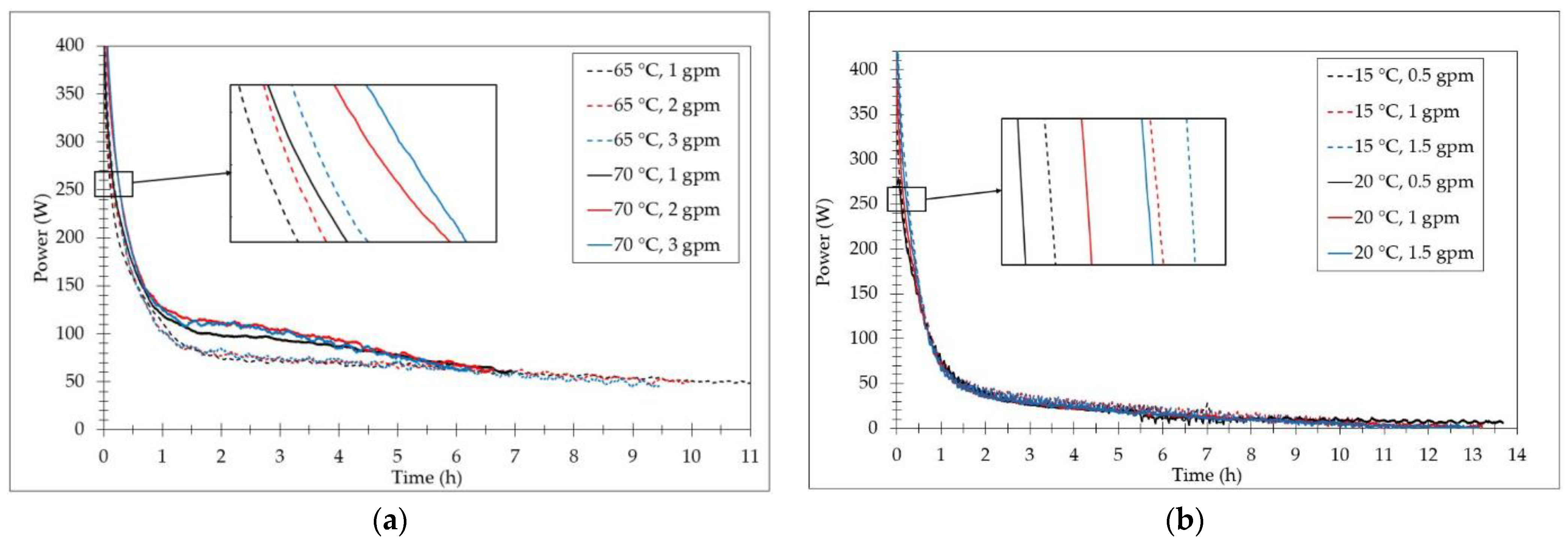
The average system energy responses of the 10 annular fin configurations during charging and discharging are shown in
Figure 6a,b, respectively. In the first two hours of both cases, the system experiences a rapid energy change, or thermal shock. This is due to the large and sudden temperature differences between the HTF and PCM. After the initial shock, the rate of energy exchange remained relatively constant while still trending downward for the rest of the test. Based on this behavior, thermal shock is the most impactful factor in processing times and will be compared between the cases. In
Figure 6a, the system’s final energy response at 65 °C and 70 °C is relatively the same for all flow rates. For clarity, the initial response difference between the flow rates can be seen in the zoomed-in portion of the graph. It becomes clear that the higher flow rate and temperature lead to a higher amount of energy absorbed by the PCM during thermal shock. These responses prove that temperature plays a more dominant role in decreasing charging time than flow rate. For the charging tests, the 70 °C at 3 gpm absorbed the energy in the shortest amount of time. After 0.5 h, the flow rates separated based on the HTF temperature due to the influence of natural convection. At 70 °C, greater initial conduction allows for natural convection to begin sooner.
On the other hand, the discharging tests showed a slightly different trend. Similarly, for discharging, the HTF at 15 °C and 1.5 gpm will have the energy dissipated in the shortest amount of time. In the zoomed-in portion of
Figure 6b, it can be seen that 15 °C, the lower temperature, increases the amount of energy dissipated in the first two hours of the test; however, it is only significant for 1 and 1.5 gpm. The energy dissipated by the 20 °C tests at 1 and 1.5 gpm overtakes the energy response of 15 °C and 0.5 gpm. Unlike charging, discharging energy responses do not split because natural convection does not play a significant role in this process.
The 20 annular charging and discharging average energy responses are shown in
Figure 7a,b, respectively. Both fin configurations show relatively similar energy response trends, although the 20 annular fins charge and discharge in less time. This results in energy absorption and dissipation in a shorter amount of time. In
Figure 7a, it can be seen that the energy response for the system at 70 °C is only significant at 2 and 3 gpm. Only the case with HTF at 65 °C and 3 gpm outperformed the lowest flow rate of 70 °C. This is different from the charging energy response seen in the 10 annular fin cases. The discharging energy response (
Figure 7b) is once again only significant at 15 °C for 1.5 and 1 gpm.
Based on all experimental cases, the most effective time-reduction approach is to use an increased number of fins, an increased HTF flow rate, and higher or lower HTF temperatures for charging and discharging, respectively. However, utilizing more extreme temperatures and flow rates requires greater energy consumption. This highlights the importance of determining optimum HTF parameters to properly balance processing speed and resource expenditure.


