Article

Increasing the Sustainability of the Hybrid Mold Technique through Combined Insert Polymeric Material and Additive Manufacturing Method Design

1
Centre for Polymer and Material Technologies, Department of Materials, Textile and Chemical Engineering, Ghent University, 9000 Gent, Belgium
2
Laboratory for Chemical Technology, Department of Materials, Textile and Chemical Engineering, Ghent University, 9000 Gent, Belgium
3
Centre for Textile Science and Engineering, Department of Materials, Textile and Chemical Engineering, Ghent University, 9000 Gent, Belgium
*
Authors to whom correspondence should be addressed.
Sustainability 2022, 14(2), 877; https://0-doi-org.brum.beds.ac.uk/10.3390/su14020877
Submission received: 17 December 2021 / Revised: 2 January 2022 / Accepted: 11 January 2022 / Published: 13 January 2022
(This article belongs to the Special Issue Mechanics of Sustainable Polymeric Materials)

Abstract

:
To reduce plastic waste generation from failed product batches during industrial injection molding, the sustainable production of representative prototypes is essential. Interesting is the more recent hybrid injection molding (HM) technique, in which a polymeric mold core and cavity are produced via additive manufacturing (AM) and are both placed in an overall metal housing for the final polymeric part production. HM requires less material waste and energy compared to conventional subtractive injection molding, at least if its process parameters are properly tuned. In the present work, several options of AM insert production are compared with full metal/steel mold inserts, selecting isotactic polypropylene as the injected polymer. These options are defined by both the AM method and the material considered and are evaluated with respect to the insert mechanical and conductive properties, also considering Moldex3D simulations. These simulations are conducted with inputted measured temperature-dependent AM material properties to identify in silico indicators for wear and to perform cooling cycle time minimization. It is shown that PolyJetted Digital acrylonitrile-butadiene-styrene (ABS) polymer and Multi jet fusioned (MJF) polyamide 11 (PA11) are the most promising. The former option has the best durability for thinner injection molded parts, and the latter option the best cooling cycle times at any thickness, highlighting the need to further develop AM options.

1. Introduction

Currently, an abundant amount of durable consumer products such as medical, electronic, and automobile plastic parts are produced in large quantities utilizing injection molding [1]. Before a newly designed polymeric part is mass-produced by injection molding, prototypes are required to assess the visual appearance, functionality, and mechanical performance of the new product. Prior dedicated knowledge of the product quality results in an overall reduction in both the material waste and production energy, since untested parts sometimes result in being unfit for their final purpose. Therefore, it is essential that the prototypes strongly peer with the final, non-prototype injection molded parts.
Additive manufacturing (AM) has proven to be a valuable production method in many prototyping applications [2,3]. AM methods offer great opportunities in environmentally friendly manufacturing products [4], and compressing the lead time before a newly designed part is produced [5,6]. However, in the scope of mimicking injection molded polymer parts for prototype applications, there are still some downsides. Firstly, not all polymers for injection molding can be processed using an AM method [7,8]. Secondly, the AM layer by layer building principle, specifically for more complex shapes, easily results in different intrinsic properties in comparison to injection-molded parts [8,9]. In addition, in AM, the required production time per single part can still be high [6], which leads to an increasing energy consumption if AM methods are used for large series of prototypes [10].
Innovation lies in the use of additive manufactured molds for which the production lead time, material waste, and required manufacturing energy per produced AM product [10] can be minimized and combined with conventional injection molding. Such sustainable AM inserts, containing mold cores and cavities, are inserted in a larger steel overall mold house, which should be adaptable for multiple insert geometries. The method of placing adaptable mold inserts containing the core and cavity of the injection molded product has been referred to as direct polymer additive tooling (DPAT) [11] and hybrid injection molding (HM) [12,13,14,15].
Currently, most prototype injection molds are still made via hard tooling options, for which aluminum is often chosen as mold material [16,17]. In the last two decades, HM has been already introduced more broadly in industry [15]. This sustainable manufacturing method generally includes inserts made by all rapid tooling (RT) techniques and is thus not limited to AM [12]. For example, silicone casting is an RT technique often investigated for injection mold tooling [12,15]. The high speed machining (HSM) of soft metals such as aluminum can also be applied for HM insert production [18].
Recent research on the implementation of AM techniques for mold insert production mainly reports PolyJet digital acrylonitrile-butadiene-styrene polymer (ABS) as polymeric insert material. The formulation for Digital ABS contains acrylic monomers, urethane oligomers, and epoxy moieties next to a photo-initiator to start the curing process [19]. The name originates from its purpose to simulate standard ABS regarding thermal and mechanical material properties. It had been claimed that Digital ABS inserts are applicable for over 50 shots with minor insert damage [20]. Parts produced within these inserts, however, display more brittle behavior, which can be linked to particle agglomeration, due to the low thermal conductivity of the insert material and the notch effect on the test specimens due to a higher surface roughness [21]. The achievement of a different molded part quality has also been assigned to different required injection molding process parameters for AM inserts, including Digital ABS [22]. The failure of Digital ABS inserts occurred as fractures caused by ejection forces [22] and a combination of mechanical and thermal loading during injection in small or sharp components [23]. Both types of failure occur in a relatively short time and on a small surface area due to collision with the insert material and further indicate the risk of brittle fracture. This has also been witnessed for other acrylic- and epoxy-based materials produced via VAT-based photopolymerization or stereolithography (SLA) [22,23,24].
Before the PolyJetting of Digital ABS gained popularity for the production of mold inserts, SLA was the most accustomed HM insert production method [25]. Hence, the current market is broader than Digital ABS only. SLA materials have properties similar to PolyJetted Digital ABS and therefore display similar brittle fracture behavior [24]. New developments for SLA materials might offer a better solution for mold insert production compared to Digital ABS thanks to reinforcements inside the materials, also offering a higher thermal resistance [26]. However, the low availability and high cost of these materials decreases the likeliness of their present-day industrial application [26].
In addition to the thermoset materials produced by the PolyJet and SLA methods, thermoplastic AM insert materials have also been applied to produce hybrid mold inserts. Selective laser sintering (SLS) with polyamides (PA) has been tested, and displayed a cooling behavior which was similar to Digital ABS [11]. SLS, however, is characterized by earlier product fracture during tensile tests as enhanced by the higher surface roughness [11]. SLS inserts have also been used to test conformal cooling channels within the mold inserts but did not result in an improvement of the cooling rate due to the low thermal conductivity of the material [18]. Using SLS, glass fibers can be implemented in the AM build as well, leading to an increased mold insert performance [23]. For a sustainable production, SLS also requires a significant amount of energy to enable particle fusing [27].
Furthermore, Multi jet fusion (MJF) by Hewlett-Packard (HP) is a relative new AM method which is also applicable to PA, similar to SLS in combination with the powder bed fusion (PBF) technique. MJF requires less time for particle fusion, which results in decreased temperature differences between adjacent layers and therefore a better sinter quality [27]. The build strategy allowing sintered layers to rest upon the powder present in the build vat eliminates the necessity for support structures in the SLS and MJF methods [28], which contributes to their sustainable character by eliminating material waste. The enhanced particle fusion also results in a 25% lower energy consumption for MJF compared to SLS [29]. The mechanical properties of PA parts produced via MJF have proven to be within the range of the SLS and PBF parts [28,30]. MJF has applicability for mold insert production, as illustrated in case studies focusing on the low thermal conductivity of PA12, which causes a different skin-core layer morphology as well as longer necessary cooling times [31,32].
A common sustainable advantage offered by polymeric AM inserts is the decreased energy consumption during the injection molding process. For certain desired part characteristics, high mold temperatures are required, which for steel molds must be obtained by an energy consuming temperature control system. In polymeric inserts, the same polymer morphology can be achieved due to slower cooling in the lower thermal conductive polymeric material without the need for a heating system [33].
As many AM methods and materials are thus available, an in-depth investigation of the suitability of these methods and materials for hybrid injection mold production is still required. This contribution aims to select the most suitable additive manufactured insert materials based on their mechanical and thermal properties as well as their sustainable character. Using the computer-aided engineering (CAE) software, Moldex3D, an assessment is made of the durability of the insert materials considering wear and energy consumption. This is performed as hybrid injection molds should be associated with a lower threshold, generally impacting the industry by reducing waste and advancing performance, thereby decreasing the overall time for part production.

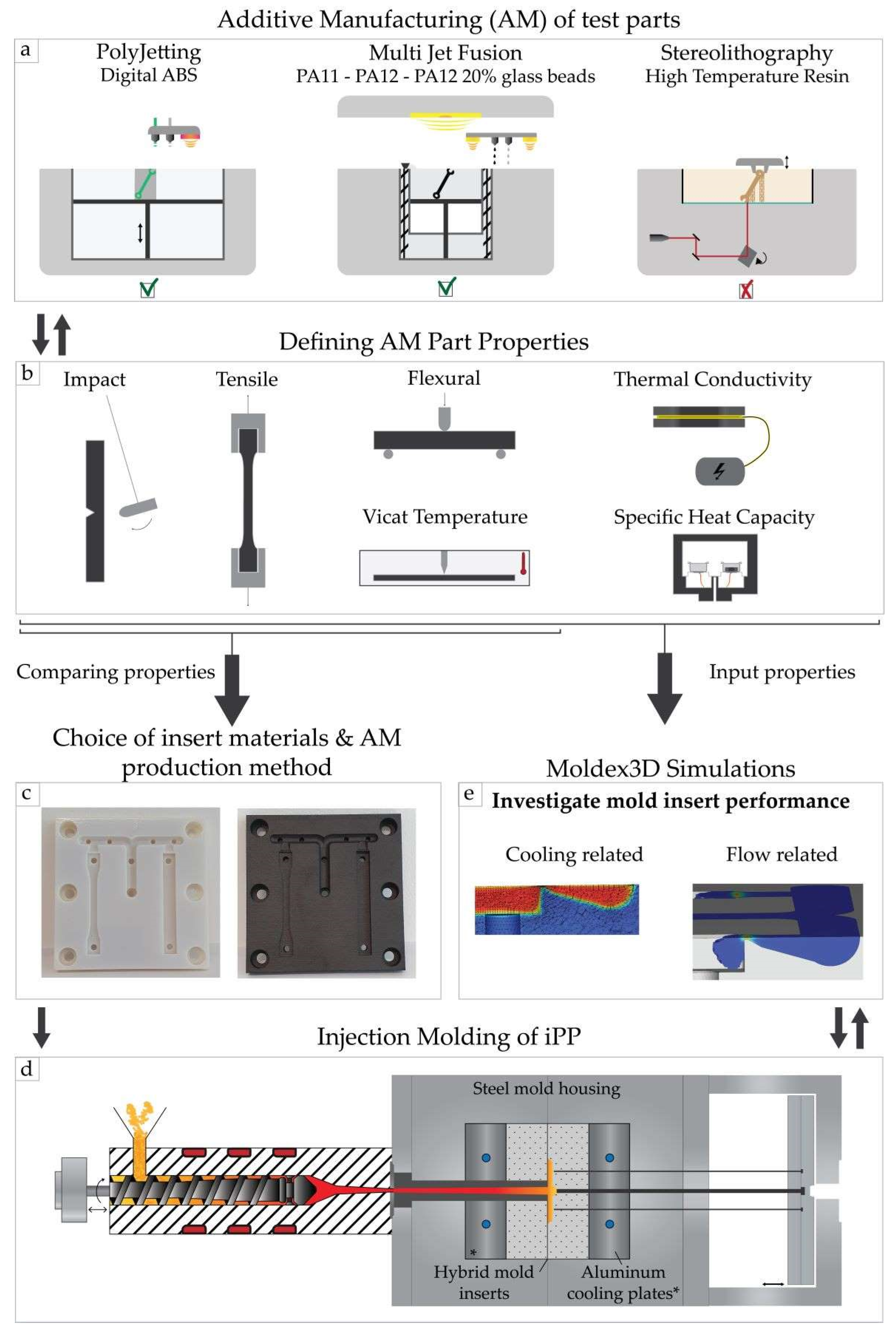
2. Materials, Experiments, and Modeling Methods

As shown in Figure 1, the practical part of this research is divided into two main parts. Firstly, five materials were combined with three types of AM methods, and the AM parts were characterized to select two optimal mold insert materials. Secondly, the obtained properties of the selected options were inputted in the Moldex3D simulation software to analyze the difference in injection molding process characteristics. The emphasis is on injecting isotactic polypropylene (iPP) in the insert materials. Such a polymer is selected as polyolefins are a major material in the overall polymer market and is often a reference testing material in many polymer engineering studies. Regarding injection molding, it is also a well-known material so that the intrinsic evaluation of the AM–HM combination can be well-studied.

2.1. Material for Injection Moulding

The polymeric material used for injection molding is an iPP grade by Polychim, named HB12XF. This material exhibits beneficial properties for injection molding, displaying a melt flow rate of 11.0 ± 2.0 g/10 min at 230 °C/2.16 kg (ASTM D1238) and a heat deflection temperature of 107 °C for 455 kPa load (ASTM D648) [34]. Furthermore, the mechanical properties of HB12XF lie within the standard range of iPP with a yield strength of 35.5 MPa and yield elongation of 10% for a tensile rate of 50 mm/min (ASTM D638), while the Izod impact strength at 23 °C is 35 J/m (ASTM D256-A) [34]. Testing this polymer for prototype production by HM is relevant as PP is one of the top three widely used polymers thanks to its high versatility in applications and low cost [35].

2.2. AM Materials and Methods for Insert Production

Three AM methods were compared, of which the general methodology is shortly explained in what follows. The first method studied is Multi-Jet Fusion (MJF) performed on an HP MJF 4210 machine. This powder-based method substantiates products by spraying an infrared (IR) light-absorbing ink in the desired shape for each thin layer. The ink functions as a fusing agent and promotes the absorption of IR light to which the material is later exposed. To enhance detail, an agent which inhibits sintering is applied onto the edges of each layer before these layers are solidified. For this research, polyamide 11 (PA11) and 12 (PA12), as well as PA12 containing 20 m% glass beads (PA12 GB), all provided by HP, have been printed and tested.
The second AM method investigated was Objet PolyJettingTM carried out on a Stratasys Objet Connex 260 machine, in which the acrylic-based resin Digital ABS PlusTM by Stratasys was used [16]. This material is designed to mimic standard ABS polymers by combining high-temperature resistance with toughness. It has the highest reported impact resistance and shock absorption of all materials used for the PolyJetTM technology [17].
The third AM method considered was stereolithography (SLA) performed on a Formlabs Form2 printer in only one print direction, since the properties need to be isotropic after full curing. The material selected for this technique was the Formlabs High Temp resin. To manufacture the samples with the most optimal dimensional properties, they were printed in a sharp angle (30°) with respect to the bottom plate of the resin vat. Afterwards, the samples had to undergo a post curing process consisting of two stages. In the first stage, the samples were exposed to Ultra Violet (UV) light with wavelengths between 300 and 400 nm at a temperature of 80 °C in an ATLAS Suntest XLS-UV oven for 2 hours. In the second stage, the samples were thermally post-cured in an oven at 160 °C for 3 hours. After cooling the samples to 23 °C and leaving them at this temperature for at least 2 days, they were tested.

2.3. Mechanical Testing

Tensile testing was performed on an Instron 5565 machine according to ISO 527 on ISO 1BA samples. The strain rate to define the modulus was 1 mm min−1, which switched over to a rate of 10 mm min−1 after the sample reached 0.3% strain. The Bluehill 2 software was used to evaluate the stress-strain curve and to calculate the Young’s modulus as the directional coefficient between 0.05 and 0.25% strain. The tensile strength is determined through the 0.2% offset method.
Flexural tests were performed on an Instron 4464 machine according to ISO 178. The specimens were deflected at a constant rate of 10 mm min−1 until the flexural extension reached the predetermined value of 15 mm flexural extension.
A Charpy impact test was performed to measure the impact energy according to ISO 179 on test bars with a 2 mm deep notch. The device used was a Tinius Olsen IT 503. A pendulum with an energy of 2.78 J was released from a height of 234.64 mm.
The Vicat softening temperature (VST) was determined to define the critical temperature at which the printed specimen started to experience substantial loss in stiffness, deteriorating mechanical properties. The test conditions were defined in Method A120 of ISO 306, which required a weight of 10 N and a heating rate of 120 °C per hour. The samples used for this measurement were 4 mm thick ends of an ISO 179 impact bar.

2.4. Physico-Thermal Testing

A HotDisk TPS 2500S device was used to measure the thermal conductivity according to the transient plane source method (TPS), following the ISO 22007-2 norm in line with our previous work [36]. For thermal conductivity measurements at elevated temperatures, a Thermtest instruments TPS-TP temperature platform was combined with the Hotdisk equipment. A Hotdisk 7577 F1 sensor with Kapton insulation was used to perform all measurements with a heating power of 20 mW for 20 s.
The specific heat capacity of PA11 and Digital ABS was measured using differential scanning calorimetry (DSC) 214 Polyma equipment from Netzsch, following the ASTM E1269 norm (similar to ISO 11357-4). The temperature interval for the measurements was going from −20 °C to 250 °C with a heating rate of 20 °C min−1. A sapphire reference with a weight of 25 mg was used for the calculations.
The solid density was measured according to ISO/DIS 1183-1, using the immersion method A with 96% ethanol as immersion liquid. A Precisa XR 205SM-DR scale was used to perform these measurements at an average environmental temperature of 22 °C.

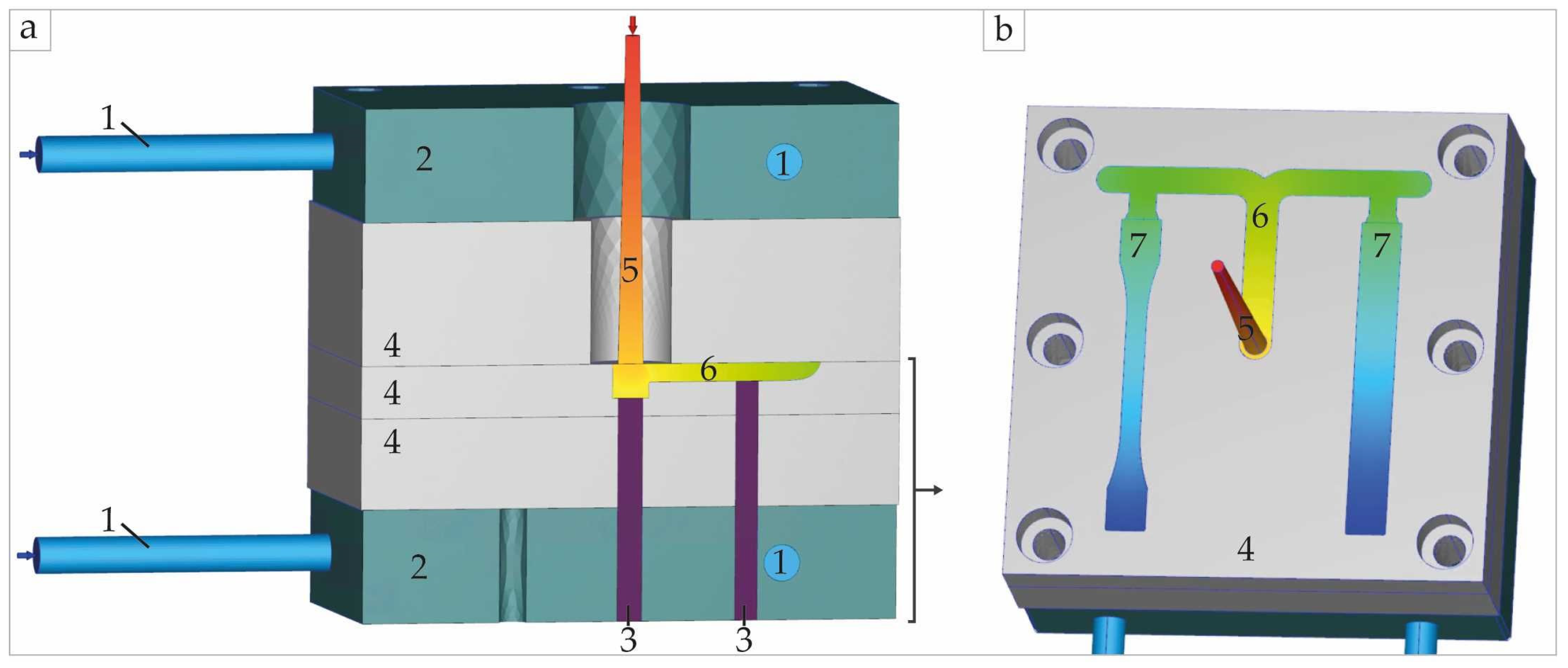
2.5. Modeling Details

Moldex3D simulation software was used for injection molding modeling. This program is one of the most widely known CAE tools for injection molding simulations [37] and is mainly used in product and mold development. The software allows each part of the mold set-up to be defined as a different object.
Figure 2 displays the employed computer-aided design (CAD) model of which each part could be assigned a suitable attribute to use for injection molding analysis by CAE with Moldex3D. For the comparison of the selected insert materials, only the material properties of the mold inserts displayed as number 4 in Figure 2 were changed. For the estimation of the effect of cavity thickness, two types of mold inserts were used in the simulations, i.e., one with 1 mm thick test bars and one with 2 mm thick test bars. All other components of the injection molding set-up are left identical for all simulations. Further info of the simulation set-up is provided in Table 1.
Before performing the simulations, the practical injection molding equipment available in our research group was manually inserted in Moldex3D to enable the use of the Machine mode 1 (by profile) setting method. Further information about the settings can be found in Table 2.

3. Results and Discussion

As previously stated, in a first step, the focus is on the comparison of the AM methods and the materials through five options, considering the test bars. After defining the two most interesting options, in a second step, the effect of the measured material properties on the durability and cooling performance of the insert materials is addressed in silico. These simulations are used to formulate guidelines to increase the sustainability of AM inserts for HM.

3.1. AM Hybrid Mold Insert Material Characterization

Five options for mold insert production via AM have been investigated: (i) Digital ABS; (ii) MJF PA11; (iii) MJF PA12; (iv) MJF PA12 GB; and (v) SLA HT-resin. For these options, mechanical and physico-thermal properties have been investigated and compared. Specifically, the mechanical characterization is highly important to assess the performance of the mold inserts during injection molding. By definition, mechanical properties are physical properties that a material exhibits upon the application of forces [38]. The better these properties are for a certain material, the more forces can be applied upon it without initiating failure. Choosing insert materials with better mechanical properties can therefore lead to the prevention of early damage to the inserts. Furthermore, insights on the dimensional quality of the inserts during application of forces can be derived from the mechanical properties.
In the present work, tensile and flexural mechanical properties are both relevant as hybrid mold inserts can bend and deform upon applying excessive injection, ejection, or clamping forces. Similarly, impact strength is important to indicate the material resilience against sharp impact forces of the injected polymer melt. The VST is used in addition as an indication of how well the mechanical properties of the materials resist elevated temperatures.
Figure 3 is a radar chart comparing the most relevant properties of the five AM options regarding their application as mold inserts, considering normalization versus maximum values per property. Table 3 presents the absolute values of all the measured properties, using test bars (top part of Figure 1). The two most interesting options are Polyjet Digital ABS and MJF PA11. As explained above, Digital ABS processed via the PolyJet technology is most often selected as insert material in hybrid injection molding studies, making it the default option. The SLA HT material mimics the mechanical performance of Digital ABS considering stiffness, strength, and toughness. This should cause a similar response in the SLA material towards injection molding settings, making its comparison with Digital ABS less interesting. Since previous research displayed brittle fraction of insert materials as an important factor limiting the lifetime of the mold inserts [24], investigating a material with higher toughness is more desired.
As can be derived from the radar chart in Figure 3, MJF PA11 has the highest toughness of all investigated materials. Furthermore, the VST and flexural strength of this material are the highest of the three MJF polyamide options. The thermal diffusivity and conductive behavior of MJF PA11 is, however, lower than the 20% glass-bead-filled PA12. However, the thermal behavior of MJF PA11 is still much higher than the behavior of Digital ABS. Previous research has stated that different thermal properties will result in different behavior of the polymer flow and cooling during injection molding [11,32], while the different mechanical properties can result in different failure behavior of the inserts [39]. Hence, upon comparing the four insert options with PolyJetted Digital ABS, it is recommendable to select multi jet fusion with PA11 as second hybrid injection mold option in what follows.
To further estimate the durable performance of the two selected hybrid insert production options, it is thus relevant to carefully compare their properties. For example, the flexural strength in Table 3 is 75% higher for Digital ABS compared to PA11. This can also be seen in Figure 4a, displaying the average flexural stress–strain diagrams of Digital ABS and PA11. This implicates that Digital ABS is capable of withstanding 75% more force applied upon the material, causing a bending deformation without initiating plastic deformation in the insert. Similarly for tensile forces applied on the inserts, as displayed in Figure 4b, Digital ABS has a higher resilience to plastic deformation, but this is less pronounced, with a 22% increase. However, the tensile results show a larger area underneath the stress–strain graph for PA11 compared to Digital ABS. This demonstrates a higher toughness of PA11, indicating that this material can withstand more forces without resulting in fracture of the insert material. This means that deformation is likely to occur faster for PA11 inserts, but a final tensile-like fracture of the material is likely to occur faster for Digital ABS. The different mechanical behavior of MJF PA11 can be beneficial for the lifetime of the mold inserts if the plastic deformation occurs in regions that have no interference with the shape of the product cavity.
As can be seen in Figure 5a, the values of thermal conductivity differ greatly upon comparing the two selected additive manufactured insert materials, PolyJet Digital ABS and MJF PA11, with the conventional mold metals, steel and aluminum. The thermal conductivity is a material-dependent parameter which indicates the rate at which heat can propagate through the specific material per unit volume and time over a steady temperature difference. The large differences in Figure 5a can be explained by the different ability of metals and polymers to transport vibrational energy, as induced by temperature increases. The much lower values of PA11 and Digital ABS result in a slower dissipation of heat through the inserts, limiting the cooling rates. This likely results in longer cooling times and an altered polymer morphology for hybrid injection molded products. Therefore, AM polymeric materials with higher thermal conductivity should perform better for the production of prototypes with material properties approximating those of conventional produced parts.
A closer inspection of Figure 5a shows that the temperature effect on the thermal conductivity acts different on metals compared to the AM materials. The metal insert materials show a constantly increasing value for thermal conductivity in the displayed temperature interval. In contrast, the conductivity value for MJF PA11 starts to decrease between 40 and 50 °C, an interval in which the glass transition of this material is situated (48.7 °C). The thermal conductivity of digital ABS in turn displays no decrease or increase over the displayed temperature interval. This indicates the relevance of a more in-depth knowledge of temperature-dependent parameters so that the specific heat has been recorded over the same temperature range. The associated results are displayed in Figure 5b. For the polymer materials, strong increases are witnessed with the increasing temperature, whereas for the metals, almost no temperature dependency is recorded. This, again, confirms that cooling is different between polymers and metals.
Combining the thermal conductivity (Figure 5a) with the specific heat (Figure 5b) and the density, with density presumed constant over the temperature interval of the materials (Figure 5d), the thermal diffusivity has been calculated, and the results are displayed in Figure 5c. The thermal diffusivity is a material-dependent parameter which links the ability of a material to conduct heat with the ability of this material to store it. The differences in these values are smaller than for the thermal conductivity of the insert materials in Figure 5a, which indicates that the cooling behavior might not be extremely different at various temperatures. However, there is still a strong variation so that temperature-dependent data are useful to be considered in more advanced simulations, also bearing in mind the clearly different behavior between metals and polymers. Employing MJF PA11 and Digital ABS, lower values are found compared to the metals, and the difference in thermal diffusivity between both polymeric insert materials even starts to vanish at higher temperatures.

3.2. In Silico Verification of Wear

Moldex3D simulations have been performed to identify indicators of early wear for the polymeric insert materials. The reproducibility of the injection pressure is a good first indicator to assess the quality of injected parts [40]. To enable polymer injection, the screw in the injection unit is moved forward by a hydraulic or electric system, which generates pressure on the melt in front of the screw tip. This pressure causes the melt to flow through the sprue, into the runner system, and, ultimately, the cavity. In Moldex3D, the injection pressure is defined at the melt entrance into the injection molding set-up, thus the sprue entrance. After filling, the compression phase starts as part of the holding phase, in which the pressure peaks up to the highest values of the injection cycle and therefore has the greatest impact on the necessary clamping force [41].
Figure 6 (dashed lines) represents the injection pressure results during filling and packing of iPP in the four insert materials from Figure 5, hence, the two selected insert options from Figure 3 and the two conventional materials, steel and aluminum. A distinction is made between the results for 1 and 2 mm injection molded parts, and a specific indication of the end of filling (EOF) time is included. The maximal required injection pressures are higher for the steel and aluminum inserts compared to the polymeric inserts. This can be explained by the faster solidification of the polymer melt near the mold walls in highly thermal conductive metal inserts compared to the polymeric inserts. The faster solidification near the mold walls causes the amorphous skin-layer to be quickly formed during filling, decreasing the cross-section of the cavity, and resulting in a higher polymer pressure during filling (max. in PA11: 29.3 MPa; max. in steel: 34.3 MPa). The deviating injection pressure between conventional and hybrid cycles therefore does not indicate direct wear variations but altered intrinsic properties of products produced via both production techniques due to a different melt distribution.
Figure 6 (full lines) shows the clamping force variations. Parallel monitoring of the clamping force during filling and packing is relevant for HM applications to predict possible deformation of hybrid inserts. The deformation of the insert materials might occur if pressure is initiated on the mold halves that is higher than the mechanical strength of these materials. Applying forces on the inserts which exceed the mechanical strength of the materials causes irreversible damage to the polymer structure, which is better known as plastic deformation. Hence, the clamping force can be seen as a second wear indicator. It follows from Figure 6 (full lines) that higher clamping forces are related to higher injection pressures. However, the clamping forces shall not directly lead to fracture of the inserts, but once the internal polymer structure is compromised, applying the same amount of force repeatedly on this material can decrease the mechanical strength and result in fracture at lower forces than expected from the flexural tests. The flexural strength is ideally used to assess the insert performance, since the flexural strength forms the combined result of tensile and mainly compression forces inside the test specimens [42]. Together with a high likeliness of bending deformation in the hybrid inserts, flexural strength therefore provides the best indication of the material’s resilience against an applied clamping force.
The maximum clamping pressures applied on the insert materials during the injection cycles from Figure 6 are represented in Table 4. Upon comparing the values in Table 4 with the flexural strength data displayed in Table 3, which are also repeated as the last row in Table 4, the use of PA11 inserts for parts with a thickness below 2 mm seems disadvantageous for the lifetime and accuracy of hybrid mold inserts. On the other hand, Digital ABS should be able to endure the necessary clamping forces without causing plastically deformed inserts for the investigated thickness range.
The interpretation of Figure 6 and Table 4 makes clear that it is also relevant to study simulated shear rates and stresses, making them a third wear indicator [43]. This is further supported by the indication that largely deviating thermal properties of the AM inserts compared to steel and aluminum inserts can lead to a different flow pattern, due to a different skin-shear-core layer behavior [44]. Typical locations exhibiting this behavior are gates and sharp corners [45]. Locations presenting higher shear are also known to result in locally higher temperatures, due to viscous dissipation [44], which on its own could also be used as a fourth wear indicator.
Figure 7 represents the simulation results comparing the shear stress on the polymer-insert interface and the insert temperature at the gate upon entering the 2 mm impact test bar. The maximum stresses which are applied upon the insert materials cannot be obtained from the Moldex3D simulation results, but stresses present on the interface between the injected polymer and the insert can be derived and presumed to be transferred directly to the insert material. It follows from Figure 7 (top row) that due to a higher ABS insert temperature, the polymer flow is enhanced in the Digital ABS inserts, leading to lower shear stress concentrations near the gate and in the corner of the parts. Still, the maximum shear stress’ values in both inserts are much below the tensile strengths, as shown in Table 5. Previous research stated that the resilience of metallic mold materials towards shear related wear by filled polymers can best be expressed by the material hardness [46,47]. For the injection of unfilled polymer melt in AM inserts, however, a local elongation deformation of the insert material in the flow direction is most likely to occur. Therefore, the shear stresses in both hybrid inserts are recorded and compared to their tensile strength.
Considering the current shear stress results, typical locations which are subdued to more shear, such as the gates in Figure 7, are not expected to limit the applicability of both hybrid mold insert materials. However, it is important to keep in mind that the tensile strength is only known at room temperature and not at the higher temperatures at which the inserts are exposed to the shear stresses. This makes the occurrence of damage due to shear more likely. Specifically for ABS, a stronger (negative) influence of temperature increases is expected based on the higher temperatures in Figure 7 (bottom row). Therefore, more research is still required to gain further knowledge on the insert material performance under realistic injection molding conditions.

3.3. In Silico Verification of Cooling Cycle Time

In addition to wear minimization, it is from an energetic point of view worthwhile to minimize the cooling cycle time. It can be expected that the much lower thermal conductivity and diffusivity values of the polymeric inserts compared to those found for metallic inserts, result in a slower cooling of the polymer melt and, hence, longer cooling cycle times. Too long injection cycle times are economically undesirable and will therefore have a negative impact on the applicability of HM, encouraging industry to fall back on less sustainable production options. This makes calculating the cooling cycle time increase upon using materials with lower thermal conductivity and diffusivity values important.
Figure 8 provides the cooling profiles of parts with a thickness of 1 mm (subplot a) and 2 mm (subplot b) by the volume% of the injected part that has reached the ejection temperature of 90 °C. As expected, slower cooling takes place in the polymeric inserts. Specifically for parts with a larger thickness of 2 mm, the increase in cooling time becomes more pronounced, with the longest times required in the Digital ABS inserts. The necessary cooling time of parts produced in PA11 inserts is 71.6% (1 mm) and 59.5% (2 mm) compared to parts produced in the Digital ABS inserts. For the steel and aluminum inserts, one obtains counterpart values of 20.5% and 18%, respectively. Hence, the metal inserts cool much faster, but PA11 shows a greater potential than ABS opposed to the wear results, highlighting the relevance of the present work aiming at a dedicated comparison of both wear and cooling cycle time.
It can, however, be expected that a certain threshold value for the thermal conductivity and diffusivity of polymeric insert materials exists. After this threshold, the cooling time is no longer expected to decrease upon considering better thermal properties, as for instance clear from the very similar results for both metals in Figure 8.

4. Conclusions

From the comparison of the five material-AM options, Digital ABS as processed by PolyJet technology and PA11 as processed by MJF are the most suited for hybrid injection mold insert applications. From a sustainability point of view, MJF PA11 scores the best thanks to its lower material waste and energy consumption during processing. The lower thermal properties of Digital ABS result in a strongly increased required cooling cycle time compared to parts produced in MJF PA11 inserts, which might limit its applicability and economical interest. From a durability point of view, Digital ABS is expected to be applicable over a longer lifetime owing to its better resilience against clamping forces and the occurrence of lower shear stresses near the mold walls. The durability of MFJ PA11, however, largely increases by increasing the thickness of the injection molded part.
The cavity surface temperature of the Digital ABS inserts has a higher increase during an injection molding cycle compared to MJF PA11 due to the lower thermal conductivity and diffusivity of the Digital ABS polymer. This makes thermal degradation in Digital ABS more likely, therefore enhancing the likelihood of interference with the mechanical integrity of the inserts.
Globally, the current work suggests that MJF PA11 is preferred as a sustainable hybrid mold insert material for parts with an average or larger than average thickness. However, further research is still required to assess the mechanical performance of the insert materials at higher temperatures, combined with a practical assessment of the lifetime and deformation of the hybrid insert material.

Author Contributions

Conceptualization, E.F., M.E., D.R.D., and L.C.; methodology, E.F., R.F., and M.E.; software, E.F.; investigation, E.F.; resources, L.C.; writing—original draft preparation, E.F.; writing—review and editing, M.E., R.F., D.R.D., and L.C.; supervision, D.R.D. and L.C.; funding acquisition, L.C. All authors have read and agreed to the published version of the manuscript.

Funding

D.R.D. acknowledges the research foundation—Flanders (FWO Flanders; project number: G0E7119N).

Data Availability Statement

The raw data are available upon reasonable request to the authors.

Conflicts of Interest

The authors declare no conflict of interest.

References

  1. Low, M.L.H.; Lee, K.S. Mould data management in plastic injection mould industries. Int. J. Prod. Res. 2008, 46, 6269–6304. [Google Scholar] [CrossRef]
  2. Campbell, I.; Bourell, D.; Gibson, I. Additive manufacturing: Rapid prototyping comes of age. Rapid Prototyp. J. 2012, 18, 255–258. [Google Scholar] [CrossRef] [Green Version]
  3. Kruth, J.P.; Leu, M.C.; Nakagawa, T. Progress in additive manufacturing and rapid prototyping. CIRP Ann. Manuf. Technol. 1998, 47, 525–540. [Google Scholar] [CrossRef]
  4. Drizo, A.; Pegna, J. Environmental impacts of rapid prototyping: An overview of research to date. Rapid Prototyp. J. 2006, 12, 64–71. [Google Scholar] [CrossRef]
  5. Byun, H.S.; Lee, K.H. A decision support system for the selection of a rapid prototyping process using the modified TOPSIS method. Int. J. Adv. Manuf. Technol. 2005, 26, 1338–1347. [Google Scholar] [CrossRef]
  6. Durach, C.F.; Kurpjuweit, S.; Wagner, S.M. The impact of additive manufacturing on supply chains. Int. J. Phys. Distrib. Logist. Manag. 2017, 47, 954–971. [Google Scholar] [CrossRef]
  7. Khorram Niaki, M.; Nonino, F.; Palombi, G.; Torabi, S.A. Economic sustainability of additive manufacturing: Contextual factors driving its performance in rapid prototyping. J. Manuf. Technol. Manag. 2019, 30, 353–365. [Google Scholar] [CrossRef]
  8. Berman, B. 3-D printing: The new industrial revolution. Bus. Horiz. 2012, 55, 155–162. [Google Scholar] [CrossRef]
  9. Dawoud, M.; Taha, I.; Ebeid, S.J. Mechanical behaviour of ABS: An experimental study using FDM and injection moulding techniques. J. Manuf. Process. 2016, 21, 39–45. [Google Scholar] [CrossRef]
  10. Faludi, J.; Bayley, C.; Bhogal, S.; Iribarne, M. Comparing environmental impacts of additive manufacturing vs traditional machining via life-cycle assessment. Rapid Prototyp. J. 2015, 21, 14–33. [Google Scholar] [CrossRef] [Green Version]
  11. Kampker, A.; Triebs, J.; Kawollek, S.; Ayvaz, P.; Beyer, T. Direct polymer additive tooling—Effect of additive manufactured polymer tools on part material properties for injection moulding. Rapid Prototyp. J. 2019, 25, 1575–1584. [Google Scholar] [CrossRef]
  12. Pouzada, A.S. Hybrid moulds: A case of integration of alternative materials and rapid prototyping for tooling. Virtual Phys. Prototyp. 2009, 4, 195–202. [Google Scholar] [CrossRef]
  13. Martinho, P.M.G. Mechanical Design of Hybrid Moulds—Mechanical and Thermal Performance. Ph.D. Thesis, Universidade do Minho, Braga, Portugal, 2010. [Google Scholar]
  14. Witt, G.; Sridhar, A.; Attanasio, D.C.; Kehrberger, R.; Hopkinson, N. Application and modelling of hybrid stereolithography injection mould tooling. Virtual Phys. Prototyp. 2006, 1, 197–206. [Google Scholar] [CrossRef] [Green Version]
  15. Hussin, R.; Sharif, S.; Nabiałek, M.; Rahim, S.Z.A.; Khushairi, M.T.M.; Suhaimi, M.A.; Abdullah, M.M.A.B.; Hanid, M.H.M.; Wysłocki, J.J.; Błoch, K. Hybrid mold: Comparative study of rapid and hard tooling for injection molding application using metal epoxy composite (MEC). Materials 2021, 14, 665. [Google Scholar] [CrossRef]
  16. Medesi, A.J.; Wohlgemuth, J.; Franzreb, M.; Hanemann, T. Ceramic Injection Moulding using 3D-Printed Mould Inserts. Ceram. Mod. Technol. 2019, 2, 104–110. [Google Scholar] [CrossRef]
  17. Noble, J.; Walczak, K.; Dornfeld, D. Rapid tooling injection molded prototypes: A case study in artificial photosynthesis technology. Procedia CIRP 2014, 14, 251–256. [Google Scholar] [CrossRef] [Green Version]
  18. Taylor, C.M.; Ilyas, I.P.; Dalgarno, K.W.; Gosden, J. Manufacture of production quality injection mold tools using SLS and HSM. In Proceedings of the ASME 2007 International Manufacturing Science and Engineering Conference, Atlanta, GA, USA, 15–18 October 2007; pp. 9–16. [Google Scholar] [CrossRef]
  19. Stratasys. Digital ABS Plus Datasheet. 2018. Available online: https://www.stratasys.com/materials/search/digital-abs-plus (accessed on 9 September 2021).
  20. Volpato, N.; Solis, D.M.; Costa, C.A. An analysis of Digital ABS as a rapid tooling material for polymer injection moulding. Int. J. Mater. Prod. Technol. 2016, 52, 3–16. [Google Scholar] [CrossRef]
  21. Kumar, S.; Singh, A.K. Volumetric shrinkage estimation of benchmark parts developed by rapid tooling mold insert. Sadhana Acad. Proc. Eng. Sci. 2020, 45, 139. [Google Scholar] [CrossRef]
  22. Simpson, P.; Zakula, A.D.; Nelson, J.; Dworshak, J.K.; Johnson, E.M.; Ulven, C.A. Injection molding with an additive manufactured tool. Polym. Eng. Sci. 2019, 59, 1911–1918. [Google Scholar] [CrossRef]
  23. Kampker, A.; Triebs, J.; Ford, B.A.; Kawollek, S.; Ayvaz, P. Potential analysis of additive manufacturing technologies for fabrication of polymer tools for injection moulding—A comparative study. In Proceedings of the 2018 IEEE International Conference on Advanced Manufacturing (ICAM), Yunlin, Taiwan, 16–18 November 2018. [Google Scholar]
  24. Colton, J.S.; Crawford, J.; Pham, G.; Rodet, V.; Wang, K.K. Failure of rapid prototype molds during injection molding. CIRP Ann. Manuf. Technol. 2001, 50, 129–132. [Google Scholar] [CrossRef]
  25. Segal, J.I.; Campbell, R.I. A review of research into the effects of rapid tooling on part properties. Rapid Prototyp. J. 2001, 7, 90–98. [Google Scholar] [CrossRef]
  26. Bagalkot, A.; Pons, D.; Symons, D.; Clucas, D. Categorization of of Failures Failures in Used for Injection Molding. Processes 2019, 7, 17. [Google Scholar] [CrossRef] [Green Version]
  27. Cai, C.; Tey, W.S.; Chen, J.; Zhu, W.; Liu, X.; Liu, T.; Zhao, L.; Zhou, K. Comparative study on 3D printing of polyamide 12 by selective laser sintering and multi jet fusion. J. Mater. Process. Technol. 2021, 288, 116882. [Google Scholar] [CrossRef]
  28. Monti, G.L.; Montanari, S. Production cost model of the multi-jet-fusion technology. Proc. Inst. Mech. Eng. Part C J. Mech. Eng. Sci. 2019, 235, 1917–1929. [Google Scholar] [CrossRef]
  29. London, M.B.; Lewis, G.M.; Keoleian, G.A. Life Cycle Greenhouse Gas Implications of Multi Jet Fusion Additive Manufacturing. ACS Sustain. Chem. Eng. 2020, 8, 15595–15602. [Google Scholar] [CrossRef]
  30. O’Connor, H.J.; Dickson, A.N.; Dowling, D.P. Evaluation of the mechanical performance of polymer parts fabricated using a production scale multi jet fusion printing process. Addit. Manuf. 2018, 22, 381–387. [Google Scholar] [CrossRef]
  31. Boden, S.; Wieme, T.; Erkoç, M.; Cardon, L. Thermal Behaviour of Hybrid Injection Moulds for Short Production Series. In Proceedings of the International Conference on Polymers and Moulds Innovations—PMI, Braga, Portugal, 19–21 September 2018. [Google Scholar]
  32. Fernandez, E.; Vande Ryse, R.; Cavicchiolo, L.; D’hooge, D.R.; Cardon, L. Optimising open and closed cooling time for hybrid injection moulding of polypropylene with polyamide inserts from multi jet fusion. Plast. Rubber Compos. 2021, 50, 137–145. [Google Scholar] [CrossRef]
  33. Tábi, T.; Kovács, N.K.; Sajó, I.E.; Czigány, T.; Hajba, S.; Kovács, J.G. Comparison of thermal, mechanical and thermomechanical properties of poly(lactic acid) injection-molded into epoxy-based Rapid Prototyped (PolyJet) and conventional steel mold. J. Therm. Anal. Calorim. 2016, 123, 349–361. [Google Scholar] [CrossRef] [Green Version]
  34. Polychim Industrie. Datasheet Polypropylene Homopolymer HB12XF. 2012. Available online: http://www.polychim-industrie.com/docs/FT_HB12XF_ASTM_En_1.pdf (accessed on 14 August 2021).
  35. Yoshino, K.; Yin, X.H.; Sugimoto, R.; Uchikawa, N.; Chemicals, M.T.; Industries, M.C.; Amagasaki, M. Structure and Properties of Syndiotactic Polypropylene. In Proceedings of the 1995 International Symposium on Electrical Insulating Materials, Tokyo, Japan, 17–20 September 1995; pp. 355–358. [Google Scholar]
  36. Wieme, T.; Tang, D.; Delva, L.; D’hooge, D.R.; Cardon, L. The Relevance of Material and Processing Parameters on the Thermal Conductivity of Thermoplastic Composites. Plast. Rubber Compos. 2018, 58, 466–474. [Google Scholar] [CrossRef] [Green Version]
  37. Islam, A.; Li, X.; Wirska, M. Injection Moulding Simulation and Validation of Thin Wall Components for Precision Applications; Springer International Publishing: Poznan, Poland, 2019; Volume 4, ISBN 9783030169435. [Google Scholar]
  38. Mechanical Properties—Latest Research and News|Nature. Available online: https://0-www-nature-com.brum.beds.ac.uk/subjects/mechanical-properties (accessed on 26 October 2021).
  39. Krizsma, S.; Kovács, N.K.; Kovács, J.G.; Suplicz, A. In-situ monitoring of deformation in rapid prototyped injection molds. Addit. Manuf. 2021, 42, 102001. [Google Scholar] [CrossRef]
  40. Montanes, N.; Quiles-Carrillo, L.; Ferrandiz, S.; Fenollar, O.; Boronat, T. Effects of Lignocellulosic Fillers from Waste Thyme on Melt Flow Behavior and Processability of Wood Plastic Composites (WPC) with Biobased Poly(ethylene) by Injection Molding. J. Polym. Environ. 2019, 27, 747–756. [Google Scholar] [CrossRef]
  41. Chen, J.-Y.; Liu, C.-Y.; Huang, M.-S. Tie-Bar Elongation Based Filling-To-Packing Switchover Control and Prediction of Injection. Polymers 2019, 11, 1168. [Google Scholar] [CrossRef] [PubMed] [Green Version]
  42. Sims, G.D. Fatigue test methods, problems and standards. In Fatigue in Composites; Woodhead Publishing Limited: Sawston, UK, 2003; pp. 36–62. [Google Scholar]
  43. Bogaerts, L.; Moens, D.; Faes, M. On the Effect of Shear Rates on the Mechanical Reliability of Additive Manufacturing Plastic Moulds. In Proceedings of the International Conference on Polymers and Moulds Innovations, Guimarães, Portugal, 19–21 September 2018. [Google Scholar]
  44. Viana, J.C. Development of the skin layer in injection moulding: Phenomenological model. Polymer 2004, 45, 993–1005. [Google Scholar] [CrossRef]
  45. Bergstrom, J.; Thuvander, F.; Devos, P.; Boher, C. Wear of die materials in full scale plastic injection moulding of glass fibre reinforced polycarbonate. Wear 2001, 251, 1511–1521. [Google Scholar] [CrossRef] [Green Version]
  46. Crema, L.; Lucchetta, G. A study of mold friction and wear in injection molding of plastic-bonded hard ferrite. In Key Engineering Materials; Trans Tech Publications Ltd.: Bäch, Switzerland, 2014; Volume 612, pp. 460–472. [Google Scholar] [CrossRef]
  47. Zabala, B.; Fernandez, X.; Rodriquez, J.C. Mechanism-based wear models for plastic injection moulds. Wear 2019, 441. [Google Scholar] [CrossRef]
Figure 1. Combined experimental and modeling research for more sustainable inserts for hybrid molding: (a) additive manufacturing (AM) of test parts (e.g., tensile bar) using 3 different AM methods and 5 materials; (b) overview of AM part properties considered for execution of (a). Upon comparing of the properties, specifically the mechanical ones focus in (c) on the selection of insert materials allowing combined tensile and impact part production for further investigation by (d) injection molding of isotactic polypropylene. This is supported by (e) Moldex3D simulations, in which the defined AM material properties are inputted to ensure accurate predictions.
Sustainability 14 00877 g001
Figure 2. Set-up used in Moldex3D simulations represented by: (a) a cross-section view of the full set-up and; (b) the lower part top view of the set-up, which shows the hybrid insert with produced isotactic polypropylene test bars (colors indicate melt front time results). The numbers indicate the assigned attributes clarified in Table 1, with further information about the mesh-size and specifics.
Sustainability 14 00877 g002
Figure 3. Mechanical and physico-thermal properties of the 4 options to make insert materials. The units of all axis are percentages calculated by taking the highest measured value as reference. The maximum measured value is also displayed. Absolute values of the measured properties can be found in Table 3, also explaining the absence of two Vicat softening temperature (VST) values.
Sustainability 14 00877 g003
Figure 4. Stress–strain curves for the two selected materials/methods based on Figure 3: (a) flexural stress and (b) tensile stress displaying the strength via the 0.2% offset method.
Sustainability 14 00877 g004
Figure 5. For the selected insert materials (same as in Figure 4) as well as two conventional metals: (a) thermal conductivity at multiple working temperatures; (b) specific heat capacities at multiple working temperatures; (c) thermal diffusivity calculated using the data from (a,b,d); (d) the density measured at 22 °C, as this parameter is presumed to remain constant over the considered temperature interval.
Sustainability 14 00877 g005
Figure 6. Variation of the in silico wear indicators sprue pressure and required clamping force during the filling for injection of isotactic polypropylene (iPP): (a) 1 mm thickness parts and; (b) 2 mm thickness parts with a constant injection velocity of 15 mm s−1. Focus on two selected options from Figure 3 and two conventional systems based on steel and aluminum. The numbers 1–4 are referring to the melt front filling stages, which are also shown in the pictogram displaying filling of the sprue (1), runner system (2 and 3), and test bars (3 and 4). Stage (3) is the transition where the polymer flows through the gate and enters the part of the test bars; EOF: end of filling.
Sustainability 14 00877 g006
Figure 7. Maximum shear stress and temperature during an injection molding cycle in hybrid mold inserts as third and fourth in silico wear indicator. Focus is put on the gate region of the impact test bar during filling as the highest shear stresses possibly impacting the lifetime of the mold inserts occur there.
Sustainability 14 00877 g007
Figure 8. Cooling performance for same insert options and conventional counterparts as in Figure 6: (a) 1 mm thickness and (b) 2 mm thickness results. These subplots display the volume % (V%) of the injected part which has reached the pre-defined ejection temperature of 90°C versus the cooling cycle time. The data recording starts at the end of filling, which is 0.815 s for the 1 mm inserts and 0.980 s for the 2 mm inserts. The data in (c) display the necessary time for 99 V% of the injected parts to reach the ejection temperature.
Sustainability 14 00877 g008
Table 1. Attributes with generated mesh sizes and specifics of the simulation set-up. The numbers refer to the indications in Figure 2.
AttributeGlobal Mesh SizeMesh Specifications
1Cooling channel0.7 mm-
2Mold insert: aluminum cooling blocks7 mm-
3Mold insert: ejector pins1.5 mmExponential seeding near part: factor 1, mesh size 1.5 mm
4Mold insert: hybrid molding inserts with core and cavity1.5 mm cavity 11 mm coreExponential seeding near part: factor 1, mesh size 0.5 mm
5Sprue (in steel sprue bushing)0.45 mm-
6Runner (in mold insert)0.4 mmGate face mesh size: 0.1 mm
7Final parts: tensile and impact bar0.2 mmGate face mesh size: 0.1 mm
Table 2. Moldex3D simulation process settings. These were held constant for all simulations.
Setting Value Unit
Setting methodMachine mode 1 (by profile) Engel VC80/28 Focus
Injection velocity15mm s−1
Injection pressure profile100%
VP switch over98% volume filled (excluded runner)%
Packing time15s
Packing pressure70 %EOF pressure
Melt temperature220°C
Mold temperature40°C
Ejection temperature90°C
Closed cooling time80.5s
Mold open time120s
Table 3. Properties of 5 options as potential AM insert materials (top part of Figure 1).
Mechanical/Thermal Property AM Material + Method Unit
PA11 1PA12 1PA12 GB 1Digital ABS 2HT Resin 3
Youngs Modulus1793 ± 301893 ± 412631 ± 642465 ± 2262825 ± 183MPa
Tensile Strength32 ± 1.232 ± 2.224 ± 1.039 ± 718 ± 0.5MPa
Flexural Modulus2020 ± 912214 ± 2352764 ± 813326 ± 933492 ± 79MPa
Flexural Strength54 ± 3.051 ± 5.237 ± 1.595 ± 3.294 ± 5MPa
Impact Strength 5.57 ± 0.134.29 ± 0.413.90 ± 0.071.69 ± 0.382.23 ± 0.23kJ m−2
Vicat Temperature188.5175.6174.644°C
Density 1047 ± 21002 ± 41272 ± 91186 ± 81208 ± 3kg m−3
Degradation Temperature405402438327365°C
Thermal Conductivity0.33 ± 2 × 10⁻⁴ 0.30 ± 6 × 10⁻⁴ 0.39 ± 1.2 × 10⁻³ 0.19 ± 4 × 10⁻⁴ 0.21 ± 4 × 10⁻⁴ W (mK)−1
1 Produced via HP Multi Jet Fusion. 2 Produced via Objet PolyJetting. 3 Produced via Formlabs 2 Stereolithography (SLA). 4 No exact Vicat data could be obtained since the results were not obtained at a maximum temperature of 233 °C.
Table 4. Maximum clamping forces during an injection molding cycle in the 4 inserts from Figure 6 for injection of isotactic polypropylene (iPP) with a constant injection velocity of 15 mm s−1.
Part Thickness (mm)Max. Pressure Load Initiated by Clamping Force (MPa)
PA11Digital ABSSteelAluminum
188.686.896.097.0
250.647.953.653.0
Repeated flexural strength (MPa; Table 3)5495--
Table 5. Maximum shear stress values from Figure 7 during filling of isotactic polypropylene (iPP) in the two selected hybrid mold inserts.
Max. Shear Stress (MPa)
PA11Digital ABS
cavity2.0500.583
runner5.7905.701
Repeated tensile strength (MPa; Figure 3)32 ± 1.239 ± 7
Publisher’s Note: MDPI stays neutral with regard to jurisdictional claims in published maps and institutional affiliations.

