
Reviewing Interference for All Modes of Products for Failure Avoidance


1
Environmental Science Center, The University of Tokyo, Hongo, Tokyo 113-0033, Japan
2
SYDROSE LP, 1283 Arnold Ave., San Jose, CA 95110, USA
3
Department of Mechanical Engineering, Graduate School of Engineering, The University of Tokyo, Hongo, Tokyo 113-0033, Japan
*
Author to whom correspondence should be addressed.
Sustainability 2022, 14(3), 1743; https://0-doi-org.brum.beds.ac.uk/10.3390/su14031743
Submission received: 30 December 2021
/
Revised: 22 January 2022
/
Accepted: 25 January 2022
/
Published: 2 February 2022
(This article belongs to the Special Issue Design for Sustainability—Axiomatic Design Science and Applications)
Abstract
:Industrial products today often go through reuse or recycle for extended times and sometimes are even taken through different environments. Our product development needs to be more sustainable than ever to meet such needs. Insufficient sustainability often leads to exposing interferences that the designer overlooked and causes accidents like the three cases we discuss in this paper. Axiomatic design is a tool to aid the designer in identifying design interferences during the early design stage so the designer can remove them and create higher values through sustained use of the product. One of the three failures we discuss is a new safety feature of locking the handle shaft of a parked bicycle that accidentally kicked in while riding. The design posed a threat to the sustainability of society. The second, an automated train that started in the wrong direction and collided with the bumping post, causing societal and economic damages. The third is about conflicting functions of a part that the designers overlooked in the Fukushima Nuclear Power Plant-1, Unit-1. This disaster was and still is a threat to the social, economic, and environmental sustainability. Despite no direct fatalities, these accidents all caused serious injuries, and in the case of Fukushima, many indirect deaths. Squeezing out flaws from our designs is important in protecting people, the economy, and the environment now and for our future for sustainability. The designer should carry out failure analysis for all parts of a product in all modes of operation.
1. Introduction
Mechanical design defines the shapes of new parts, their assembly with machine elements and instrumentation, and how the sub-assemblies combine with other sub-assemblies to make products. Mechanical design of complex systems often involves groups of designers. A typical automobile design has tens of thousands of parts [1]. This paper calls the subject of the design a machine, and a machine can be small with only a few parts or huge, covering a wide area.
A mechanical designer, through the design, aims to bring value to the users or the society. This activity, however, is accompanied with the responsibility that the machines they design will not cause injury or suffering to the users, unrelated bystanders, or Earth. The designer, in addition, must also make the design free of negative effects to our future generation [2].
Modern industrialization continues to add complexity to our designs. Thus, assuring safety with designs becomes increasingly difficult. Since about the 1950s, people have developed many tools to help the designer maintain a trouble-free design. For example, finite element methods for stress analysis, computational fluid dynamics for predicting fluid flow, design review so that more people can share their knowledge for inexperienced designers, or quality control for monitoring manufacturing processes.
Design theorists, at about this time, argued that early conceptual design stage determines the product cost and its success in the market, e.g., [3]. Axiomatic design (AD) [4] is a tool that can help the designer identify troubling features of a design by pointing out interference (a part unintentionally causing effect in an unrelated part) in design. A design record graph (DRG) gives a graphic representation of the interference [5].
This paper lists three accident cases. Two of them we have already discussed in our preprint [6]; that is, a recent bicycle recall case and the 2011 Fukushima-1, Unit 1 accident. We introduce the third as another case of the designer overlooking to study all modes of the product and failing to identify a problematic design, an automated train collision with a bumping post. Many accidents are caused by the designer’s oversight. Failure analyses, intended for avoiding such happenings, may proceed with the designer trying to think of all possible failures. Such a strategy, however, may miss a critical failure mode beyond the designer’s imagination. Fine decomposition of designs with tools like AD or DRG into design parameters (DPs) or physical elements (PEs) helps the designer with failure analysis in looking into all possible failures. The designer should carry out failure analysis in all modes of the product operation.
2. Design Record Graph and Axiomatic Design
This section explains DRG and AD and how they point to interference in conceptual design.
2.1. Design Record Graph
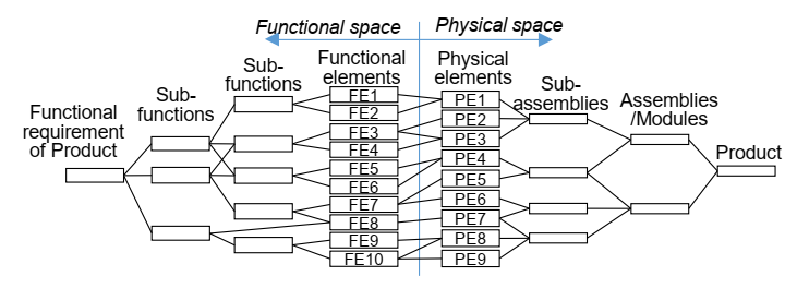
Figure 1 shows a typical DRG. It is convenient in two applications. One is in producing a new design and the other is for existing design analysis. For a new product design, the designer starts from the node at the left end, the product functional requirement. The designer then proceeds to the right by dividing the functional requirement on the left to a set of sub-functions. The subdivision continues until the designer reaches a set of functional elements (FEs). An FE is not practical for further subdivision.
The next step for the designer is to map each FE to one or more physical element (PE). A PE is typically a single machine part that produces the corresponding function (FE). This step moves the designer from the functional space into the physical space. This mapping can be one to one, one to many, or many to one. In the physical space, multiple parts assemble into assemblies and the designer collects assemblies into higher level assemblies or modules until they all combine to a single node, the product. This product at the right end is the design solution to the product functional requirement at the left end.
This DRG construction process does not necessarily progress from the left to the right. The designer often thinks of a set of machine elements to meet a need that is likely to come up after a functional decomposition. This often happens when the designer already had some experience in meeting the functional requirement. The designer is then jumping into the physical space before the subdivision in the functional space is complete. This jumping back and forth is called zig-zagging, and it also happens with AD, which we discuss in the next section.
Another application of DRG is existing product analysis. This is the application we use throughout this paper. This time, the product functional requirement, the product, and all the PEs are known. The analysis first requires identifying the FEs for the PEs, then investigating how FEs combine to make higher level functions, and PEs to assemblies. The combing progresses left in the functional space and right in the physical space until they reach their respective goals of product functional requirement and product.
2.2. Axiomatic Design
For axiomatic design (AD), FEs in DRG are functional requirements (FRs), and PEs in DRG are design parameters (DPs). The design matrix (DM) of AD highlights the correspondence among FRs and DPs with matrix elements. By defining vectors FR and DP, composed of elements FRs and DPs, respectively, AD gives the following matrix equation. AD calls this equation the design equation:
where the matrix A is the DM. The ten elements FR1 to FR10 of vector FR correspond to the ten FEs in Figure 1, and vector DP’s nine elements DP1 to DP9 of vector DP to the nine PEs in Figure 1. The following Equation (2) shows exactly the mapping across the functional and physical spaces in the DRG representation in Figure 1. The two representations show the mapping among elements of functional and physical spaces.
FR= A DP
Elements of the DM in Equation (2) are 0 and X. An element 0 means the corresponding DP has no influence on the FR. X, in contrast, means that the DP has some effect on the FR without quantitative indication. When the number of DPs is less than that of FRs, like in Equation (2), either there are unsatisfied FRs or the design is coupled [4].
AD calls an interference-free design “uncoupled”. In this case, the DM is diagonal, and the DRG shows each FE in the functional space maps to exactly one PE in the physical space. The DRG, in this case, gives a ladder-like structure across the functional and physical spaces.
3. Three Accident Cases
This section introduces three accident cases in the order of seriousness they caused. The first case is about a popular consumer product, a bicycle; the second is about a collision of a commuter train; and the third, an extremely complicated system, a nuclear power plant (NPP). The bicycle affected social sustainability, and for each single bike accident, an economic impact to the rider. In case of the train, a much larger damage was made to the society with not only injuries to the passengers, but also economic damage in terms of inconvenience to the passengers for a few days. The NPP accident posed a large threat to the sustainability of societies, the economy, and the environment.
3.1. A Bicycle Recall Case
First is a case where the manufacturer had to recall its product, a bicycle. A bicycle offers a simple and handy means of transportation without any operating cost other than maybe the fatigue in the feet and legs of the rider. Many consumers in Japan now choose electrically assisted bicycles to lessen the fatigue, in which case the convenience comes with the electricity cost for charging the batteries.
In 2003, one of major Japanese bicycle manufacturers introduced a device to lock the rotation of the steering shaft when the rider engages the lock on the rear wheel. The mechanism was named “single action double lock”, so it would stand out in the market. The rival companies also had steering shaft locks, however, the users had to engage them separately from the actions of rear wheel locking; in other words, they were double action double locks.
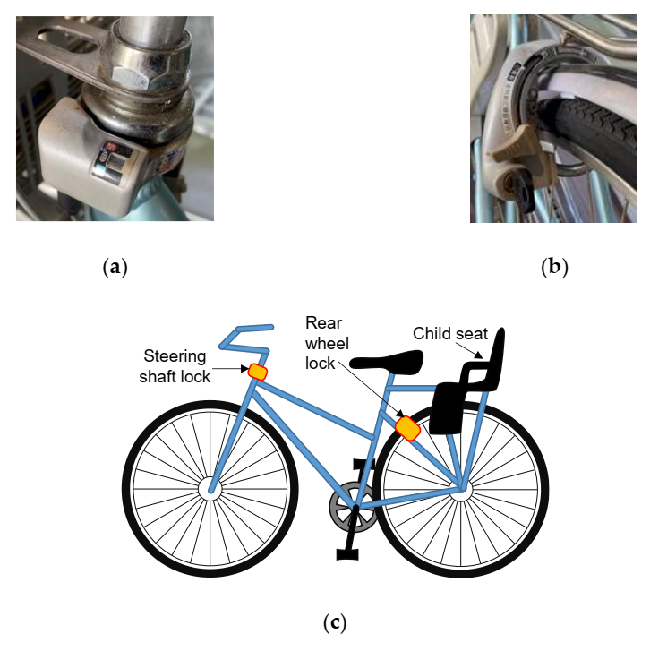
Figure 2 shows locations of the two locks, and separate photographs of the actual locks. When the rider parks the bicycle and engages the rear wheel lock, the action pushes a cable connected to the steering shaft lock that also locks the steering shaft rotation.
The rear wheel lock disables the rear wheel rotation upon parking the bicycle to prevent theft. The steering shaft lock, developed recently, offers two features. One prevents the bike from toppling over when the rider parks it on a sloped surface. The other popular feature for parents of small children is that it keeps the bike stable when they are lifting a child into the child seat.
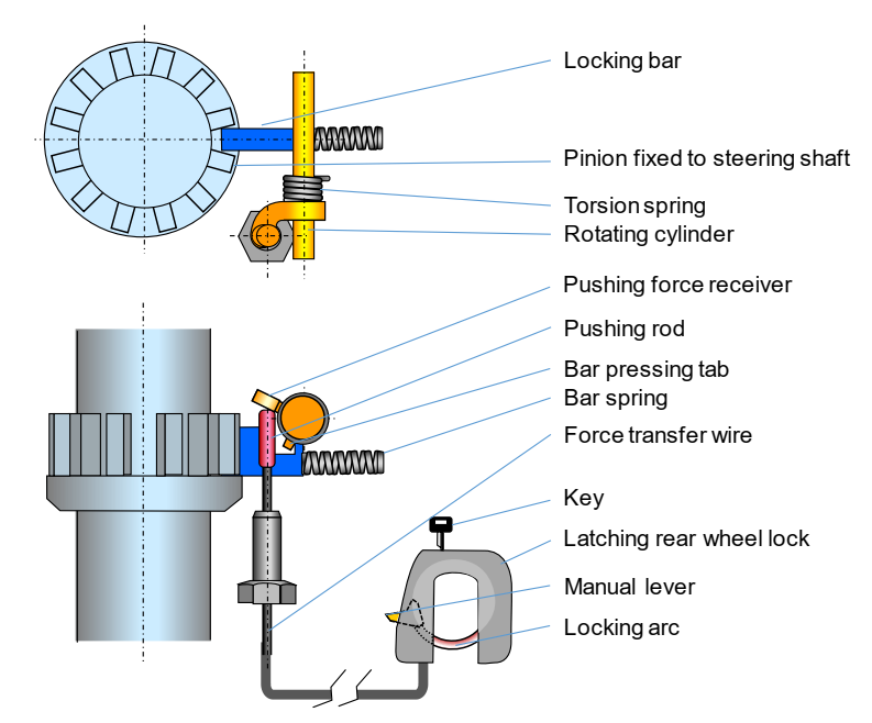
The single action double lock mechanism has parts shown in Figure 3 [7]. A housing case holds the steering shaft lock parts in position. A window shows the lock status. The upper left photo in Figure 2 shows this case. It is the gray box with a black indicator window.
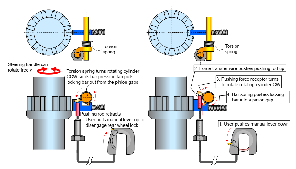
Figure 4 shows the mechanism of the single action double lock. The left figure is when the shaft is unlocked, and the right figure is when it is locked. The movements 1 through 4 take place simultaneously; these numbers are for easier visualization of the mechanism.
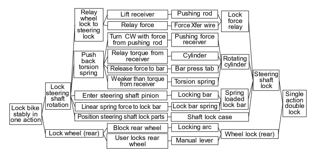
Figure 5 shows the DRG for this locking system. The arcs from FEs connect to the PEs all in a one-to-one manner. Thus, the design is uncoupled in AD. Equation (3) shows the AD design equation.
The above discussion is about how the “single action double lock” activates when parking. A rather more important function of a bike, however, is to ride it. Figure 6 is the DRG for the function of riding a bike. The figure does not have the detail of the braking system that has a number of parts, nor the detail of the locking system.
The locking system is not shown in Figure 6. To show it, one can add the function of “keep double lock engaged when parked” with the mechanism of the “single action double lock”, or combining Figure 6 and Figure 7 will give a complete picture.
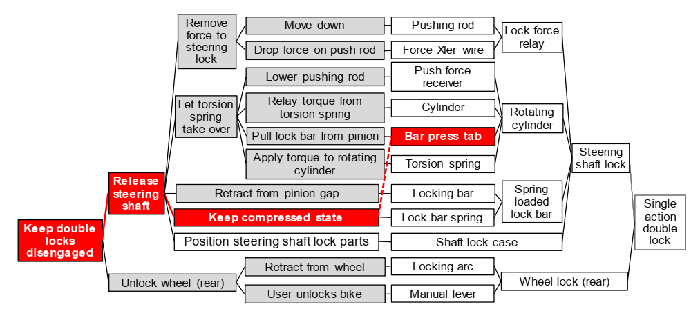
Figure 7 shows the “single action double lock” mechanism when the rider is riding the bicycle. This time, the rear wheel lock has to be disengaged and the steering shaft free to rotate. All parts in the DRG change their functions from those in Figure 5 including the higher level sub-functions to the overall function of “Keep double locks disengaged”. One exception is the “Shaft lock case”, with the function of “Position steering shaft lock parts”.
With the knowledge that the “single action double lock” was responsible for the recall, we examine the system closely in the riding mode. Upon design, the designer overlooked that the “Bar press tab” affected the “Lock bar spring” function of “Keep compressed state” shown with the broken red line segment across the functional and physical spaces. It needed proper alignment with the notch on the locking bar where the two pieces met.
The locking bar for engagement and retraction from a steering shaft pinion gap is made by the balance among the torsion spring, lock bar spring, and the pushing rod force. When the steering shaft is free, the pushing rod retracts (stays down in Figure 4), and the torsion spring applies counterclockwise (CCW) torque to the rotating cylinder. The CCW bar pressing tab force applied to the locking bar here overcomes the lock bar spring force, and the locking bar is pulled out from the steering shaft pinion gap, allowing free rotation of the steering shaft.
When the user parks the bike and engages the lock, the pushing rod pushes the pushing force receiver up, and gives clockwise (CW) torque to the rotating cylinder. This CW torque is stronger that the torsion spring torque, and the CCW block pressing tab force on the locking bar is removed. The lock bar spring then pushes the locking bar into a pinion gap on the steering shaft pinion, and the steering shaft is locked.
The locking bar in riding mode has the function of retracting itself from the pinion gap it engaged when the user locked the bike. The torsion spring, in the meantime, has to constantly keep its CCW torsional spring force on the rotating cylinder so that the bar pressing tab keeps the locking bar out of a pinion gap.
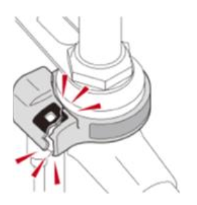
The direct cause of the recall was the shaft lock case. Possibly owing to insufficient strength, the case cracked and lost its function to hold the steering lock parts in place. The Ministry of Economy, Trade, and Industry (METI) of the Japanese government released news [8] with photographs of normal and cracked cases. Figure 8 is the illustration in the news release.
A cracked case causes the parts that it holds inside to lose tight positioning and the bar press tab can easily lose contact against the locking bar. Then, the torsion spring force fails to reach the locking bar and the bar spring pushes the locking bar into a pinion gap. This caused the steering handle to lock while the user was riding the bike. This unexpected failure caused the rider to fall on the road with the bike.
The recall involved about 3.4 million bicycles, and there had been six serious injury cases at the time of the 24 June 2019, METI press release [7]. Consumer Affairs Agency (CAA) of the Government of Japan reported a year later that the accident count during April 2019 to March 2020 amounted to 42 cases, and 11 during April to 18 August 2020 [9].
3.2. Kanazawa Seaside Line Runaway Train
The second incident we report is an automated train accident that took place on 1 June 2019, at 20:15. The passenger train on Kanazawa Seaside Line started in the wrong direction at Shin Sugita station and collided with the bumping post. Among the 25 passengers onboard, the accident injured 17 including 12 with serious injuries [10].
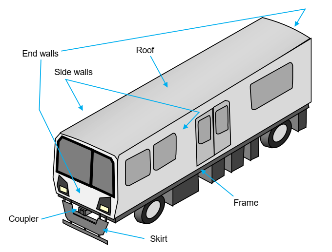
Kanazawa Seaside Line is an automated guided transit (AGT) with a total track length of 10.8 km. The rubber tires on the cars keep the rides smooth compared with conventional steel wheels on steel tracks. The line connects Shin Sugita at its north end, about 45 km south from Tokyo Station, and Kanazawa Hakkei at the south end. The line has 14 stations including the two end stations. The line runs along the port area south of Yokohama and carries commuters to port businesses and travelers visiting parks. The accident train had five cars, Car-1 to Car-5 from south to north, with 94 seats for passengers. Figure 9 shows a sketch of Car-5. No seats are available for a driver nor a conductor because the train carries no operator and operators remotely control the train from the train central control station at Namiki Central station, 3.5 km south on the line from Shin Sugita.
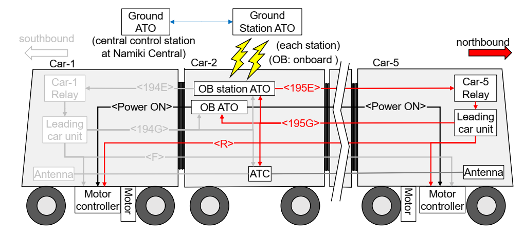
To support operators in the central control station at Namiki Central station, the train line system has several automatic control systems, among which we explain two major systems: automatic train operation (ATO) and automatic train control (ATC). Figure 10 shows these controllers.
Figure 10 shows the five-car train except, Cars 3 and 4 are cut out from the illustration. The figure shows the controllers in the state of moving the train northbound, i.e., the proper travel just before the train reached Shin Sugita station. The single-line red arrows in the figure are control lines and, for this northbound travel, lines 195E and 195G and Control Line R were energized.
ATO consists of a ground controller at the control station, a station ground controller at each station, an onboard controller for communication with the station ground controller, and another onboard train controller. The ground controller commands departure, on-time running, and stopping the trains at preset positions. The ground and onboard communication controllers exchange ground commands and train status information. The onboard controller is responsible for starting, stopping, and regulating the speed of the train by sending signals to the motors and brakes.
ATC is in use with regular trains with operators. They consist of multiple ground units along the track and an onboard ATC on each train. The onboard unit detects the speed limit from a ground unit with an antenna mounted at the head of the leading car as it passes a ground unit and compares it to the motor speed and controls the speed or stops the train if necessary.
Shin Sugita station is the terminal stop at the north end of the line and the northbound train arriving at Shin Sugita station, once it completely stops, reverses its direction to head south. The train, however, at departure, started in the northbound direction and collided with the bumping post. The bumping post was about 24.5 m away from the leading end of Car-5 when the train started moving. The train started with full acceleration and its onboard controller had the train direction registered as southbound, thus no brake engaged until Car-5′s coupler hit the bumping post.
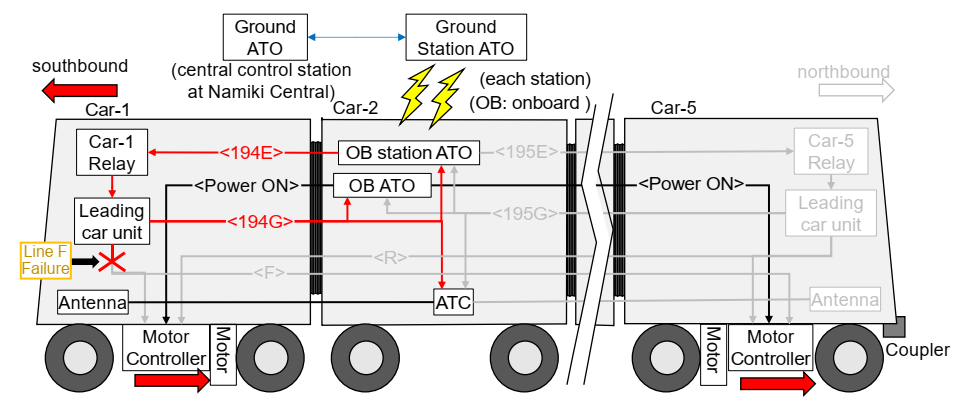
Before the accident when the incoming northbound train stopped at its terminal station Shin Sugita, all the ATO controllers operated normally as follows (angle brackets show corresponding control lines in Figure 11):
- Ground ATO: “Switch direction to south and keep stopped”
- Ground station ATO: “Switch direction to south and keep stopped”
- Onboard station ATO: “Leading car” signal to Car-1 Relay<194E>
- Car-1 Relay: “Leading car” signal to Leading car unit in Car-1
- Leading car unit in Car-1: “Leading car set” signal back to onboard station ATO<194G>
- Leading car unit in Car-1: Signal “southbound” to onboard ATO <194G>
- Leading car unit in Car-1: Signal “southbound” to ATC <194G>
- Onboard ATO: Motor Stop signal to Brake and Motor controllers
The leading car unit in Car-1 also had the function of sending the southbound signal to the three motor controllers in cars 1, 3, and 5 by energizing Control Line F that branched out to the three motor controllers. Figure 11 shows the controller communication. The accident investigation found that Control Line F was cut when the train, in its previous travel, was heading south at around the mid-point of the entire Kanazawa Seaside Line.
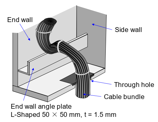
Control Line F was bundled with a number of other cables, as shown in Figure 12. The bundle was scratching against the end wall angle plate, and Control Line F happened to settle at the bottom of the bundle. The edges of this angle plate were cut with a laser cutter, and their mass production left the cut corners sharp without any filing. The through hole on the floor had a plastic fitting on top so cables in the bundle would not scratch against the metal rim of the hole. The designer overlooked that the heavy bundle, although suspended in mid-air, would sag and scratch against the end wall angle plate.
Control line F, when engaged, energizes to a control voltage of DC100 V commonly used for trains. When the coating of the line was cut deep enough, this high voltage must have caused an electric spark between line F and the angle plate electrically at ground level. Observation after the accident found the upstream side of the control line, closer to the DC100 V source, dangling, and the downstream side welded onto the stainless-steel angle plate. Later analysis revealed the weld to contain stainless-steel copper alloy, meaning the spark temperature exceeded the stainless-steel melting point of 1400 °C.
When the line failed during the train’s southbound travel, nothing unusual happened because the motor controllers were designed to hold direction commands in memory. When the train reversed its direction at the south end of Kanazawa Hakkei station, the failure again went unnoticed because, there, the Control Line R turned ON and the train successfully reversed its direction to head north (Figure 10).
At the north end of Shin Sugita station, however, the high-level controllers passed the “Reverse direction” command from the Ground ATO to Ground Station ATO, Onboard Station ATO, Car-1 Relay, Leading Car Unit in Car-1, Onboard ATO, and ATC. This signal was then passed back to Onboard Station ATO as a sign of the command being completed.
The location of the Control Line F cut was upstream of where it branched out to the motor controllers on cars 1, 3, and 5, thus none of the three motor controllers received the command signal to reverse the motor direction and just kept the last registered direction of northbound.
When it was the departure time of 20:15, the Onboard ATO sent out its Power ON signal to the three motor controllers to activate the motors. This was when the motor controller looked up its memory, which had registered northbound when Control Line R was energized at the other end, Kanazawa Hakkei station. This fail-safe function to memorize direction is necessary to engage the brakes upon emergency so the motor controller knows which direction to apply reversing torque to the induction motors.
The motors accelerated, heading north. Figure 11 shows the train high level control system with registered direction of southbound, contrary to the direction memorized in the motor controllers.
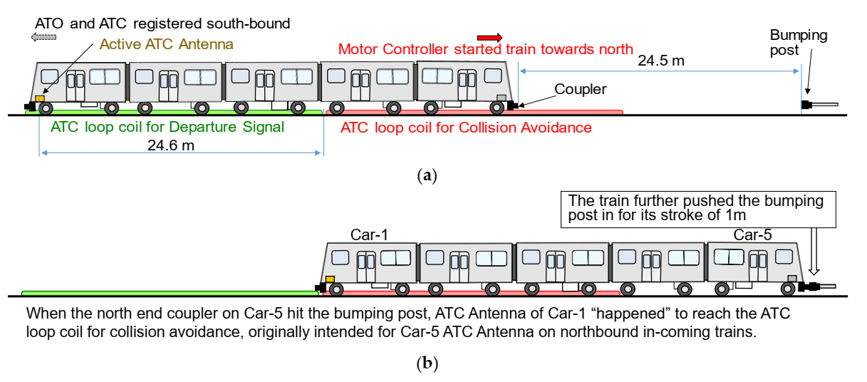
Figure 13 shows the train upon the wrong departure to its collision with the bumping post. When the train system started, it did not detect that it took off in the wrong direction. ATC, registered with southbound direction, detected its active antenna in Car-1 above the ATC loop coil for departure, a normal expectation for heading south. The train kept accelerating until the coupler of Car-5 hit the bumping post. When Car-5 collided with the bumping post, ATC antenna in Car-1 reached the south end of the loop coil for collision avoidance. This loop coil was there for the ATC antenna in Car-5 of incoming trains to detect overrun. The ATC system was not designed for trains starting off in the wrong direction, but, by a lucky coincidence, ATC engaged full brake.
When the train hit the bumping post, it had gained a velocity of about 25 km/h. The bumping post was designed to stop a train at a speed of 10 km/h with the train’s braking force. Fortunately, the train ATC engaged the brake upon reaching the bumping post; however, at a speed of 25 km/h, the bumping post, after exhausting its full 1 m damping stroke, turned into a sudden wall for the train. The ATC brake and the 1 m damping stroke of the bumping post lessened the severity of the accident to some extent.
Figure 14 shows the DRG of the train control system in setting off the train in the southbound direction. The failure that caused the accident started from Control Line F failure in the physical space. The “Memorize direction” function of the motor controller needed the “Control Line F” to be properly working. Figure 14 shows this reliance with the broken red line segment. The failure propagated into the functional space to disable the overall functional requirement of “Depart Train Southbound”.
Equation (4) is the design equation for the function of departing the train in the southbound direction. Although the number of DPs is smaller than that of FRs, this does not necessarily mean that the design is coupled. The inequality comes from mapping multiple functions to high level DPs of controllers. The X in square brackets [X] is the interference the designer overlooked, i.e., the reliance of the memory function on Control Line F.
This Control Line F in the other mode of northbound travel had the function of staying at zero, thus the cut of the line did not make a difference to the overall functional requirement in that mode.
3.3. Fukushima-1 NPP Unit 1 Accident
The 2011 “Off the Pacific coast of Tohoku Earthquake” occurred on 11 March 2011. The quake invoked tsunami waves that, about an hour later, attacked the Fukushima Daiichi Nuclear Power Plant (Fukushima-1 NPP). The wave heights surpassed elevations for which Fukushima-1 NPP was designed. Seawater entered the basements of all Fukushima-1 NPP units 1 through 6. Most of the switchboards for units 1 to 4 were in the basement. The four units entered the state of station blackout. Station blackout means a loss of all AC power [11]. Units 1 and 2 lost all their DC power.
Units 1, 2, and 3 were running at the time and all the three units succeeded in fully inserting all their control rods upon the earthquake. Unit 4 was in scheduled maintenance, so it was fully shutdown at the time. The other three units entered shutdown mode as well, thus all main steam lines and feedwater lines had their isolation valves fully closed. Reactors of units 1, 2, and 3 entered the state of core isolation. Core isolation means the core, where nuclear reaction generates heat, is isolated without active water flow around it. Although nuclear reaction had stopped, the fuel kept generating a fraction of the full power called decay heat.
Decay heat, for example, for Unit 1 was 6.4% of full power (1380 MW thermal) upon shutdown [12], and it gradually decreased with time. Without removing the heat, however, decay heat continues to boil the water inside and lowers the water level. Once the water level drops below the top of fuel bundles, fuel will begin to melt. The time left for Unit-1 to regain its lost core cooling function was 78 min after station blackout [12].
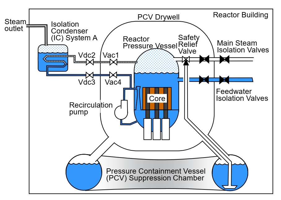
The oldest of all units, Unit 1, started operation in March of 1971. It had two identical and independent isolation condenser (IC) systems, System A and System B, designed to remove decay heat at times of core isolations. Figure 15 shows System A at core isolation.
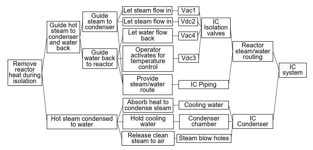
IC is a simple condenser with a cooling water filled condensing chamber. Its piping connects to the reactor pressure vessel at a high elevation filled with steam. The IC piping routes the reactor steam to the IC chamber where the steam condenses to water inside the IC piping. The piping then exits the IC chamber and connects to the recirculation piping, and the condensed water eventually returns to the reactor pressure vessel at a low elevation filled with water. This IC piping has four isolation valves: Vac1 and Vac4 in Figure 15 are two AC valves inside the pressure containment vessel and Vdc2 and Vdc3 are two DC valves outside. When in core isolation mode, Vac1, Vac4, and Vdc2 are fully open, and the operator operates Vdc3 on and off to keep the pressure vessel drop moderate to avoid damage to the pressure vessel and its components from a sudden temperature drop. Figure 16 is the DRG for the IC system in core isolation.
There was another safety feature with this IC system to prevent radiation leakage to the outside. The IC piping had a pressure sensor on it, and when the sensor detects a sudden drop in piping pressure, the controller assumes that a crack generated on the piping. Such a crack will cause the radioactive steam to escape into the condensing chamber and, as the steam outlet from the chamber simply discharges out to the atmosphere, that will lead to radiation leakage to the outside.
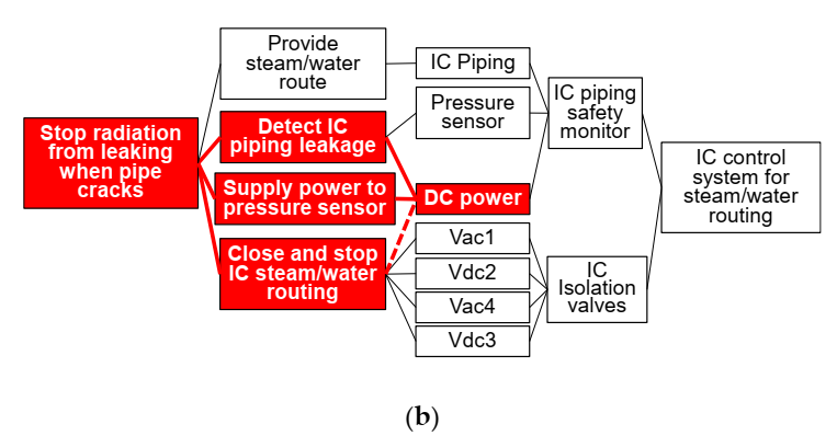
This IC shutdown mode closes all four IC isolation valves. This pressure sensor had DC power for its operation and, when the DC power is lost, the sensor loses its means of detecting cracks in the IC piping and the fail-safe design shuts down the IC function, by closing all four valves Vac1, Vdc2, Vdc3, and Vac4, in order to avoid possible radiation leakage to the outside. Figure 17 shows the DRG of this safety feature of IC shutdown.
Figure 17a is a typical DRG that a designer would draw. Note that the diagram is missing DC power to the pressure sensor, as well as the higher DC and AC powers to drive the valves. It was difficult for the designer to identify that the four valves’ “Close and stop IC steam/water routing” function were dependent on the pressure sensor’s “DC power”.
Figure 17b shows this dependence with a broken red line segment. The function of “Stop radiation from leaking when pipe cracks” needed “DC power” to the pressure sensor to be working properly; when the DC power was lost, the function activated improperly.
Equation (5) is the corresponding design equation for the DRG in Figure 17b. The design has fewer FRs than DPs. In fact, the four valves are redundant [4], and the IC flow is stopped when any one of them is closed. Nuclear plants often have such redundancy to meet functional requirements even if a structural element fails. The interference the designer overlooked is shown with the element X in square brackets [X] in Equation (5).
Evidence of this IC system failure upon the tsunami attack revealed the sequence of what happened. The pressure sensor lost its DC power first and the system commanded isolation valve closure to all four IC isolation valves.
The operator, without means of checking the valve statuses, kept operating the switch for Vdc3 valve on and off on IC System A. The operator went through the trouble of going outside to see if steam was coming out from the two steam outlets on the reactor building wall. What the operator saw was a weak rise of steam from the two holes, which was not convincing of whether or not the IC system was working. What probably happened was that the four valves, as they were closing, lost their driving power before full closure. If the IC system was in full operation, a large amount of steam would burst out from the exhaust holes with a thunder-like noise. Fukushima-1 had only tested its IC systems at the time of startup and had never tested them during the 40 years of operation. Thus, after 40 years, operators with no experience in IC activation was placed in charge of operating the emergency system.
The silent IC system caused the uncovering of the Unit 1 core and its melting. The melting process generated hydrogen gas, which leaked into the reactor building. The light-weight hydrogen gas gathered at the reactor building top floor and, a day after the station blackout, it exploded, blowing away the walls of the top floor.
4. Discussion
Section 3 reviewed three accidents; one with a consumer product that caused many injuries to users. The product was eventually recalled. Another was an accident with a public train for transportation that caused casualties, and lastly a major catastrophic NPP accident. All three accidents had the same design problem; parts that failed had to operate differently when they were in different modes.
4.1. Bicycle Recall Case
Single action double lock models were sold for both types of bicycles, with and without electric assistance. With either model, the steering handle suddenly locking its rotation during a ride is a total surprise to the rider. The event caused the rider to fall off the bike in most cases. Such a means of transportation that can harm the rider and maybe the people around it is certainly not welcome in a sustainable society.
The bicycle had different modes of parking and riding. The riding mode obviously has higher priority in terms of safety over the parking mode. Possible failure events in parking mode are theft or the bike falling over. Although theft is a definite loss and falling may cause product damage, they will not physically harm the users. The steering shaft lock was convenient for the parents when they wanted to lift their children into the child seats; however, it was just “easier”. Back in time, when bicycles did not have steering shaft locks, a parental rider just paid added attention not to let the bike topple over when they had to seat a child. We view this case as a design flaw that relied on the balance among forces from the pushing rod, the torsion spring, and the linear bar spring to keep the locking bar out of the steering shaft pinion gap, so the handle is free to rotate.
The bike manufacturer no longer has the single action double lock feature in their new products and, instead, the users have to manually turn independent steering shaft locks, just like with a competitor product. It is good that the flow of troubled bicycles has stopped; however, there are still a large number of these models in use. Over 3 million bikes with the troublesome feature were recalled [13]; however, as of the 1 December 2021, only 21.2% units had responded [14]. Consumers would research products they are about to buy new; however, once they are owners, there is little motivation in continuing to research the reputation of products they already own.
The designer, in applying AD or DRG to their design, usually writes out part names for DPs, and only the primary functions for FRs. Without executing the analysis for all modes of operation, the designer may overlook conflicting operations of parts in different modes. We have to pay special attention to whether a part function or configuration changes when the product is in a different mode. For the bicycle case, a failed part integrity caused the “Locking bar” to slide into an unwanted position while the rider was enjoying the riding mode, and for this mode, safety had the highest priority.
4.2. Passenger Train Case
The train accident not only caused bodily injury to its passengers, but it also affected other passengers in other trains of the same line because the entire line stopped. The accident took place on a Saturday, which explains the small number of passengers in the train. The line was closed until the next Tuesday, so travelers and workers on Sunday and a larger number of regular commuters on Monday had to find alternative means of transportation. The impact affected not just the passengers, but it also caused inconvenience to people. In other words, the accident affected the sustainability of society and the economy.
The accident report by Japan Transport Safety Board [10] pointed out the difficulty in recognizing the possible cut of Control Line F, and how its configuration made it difficult for the maintenance inspection to identify its vulnerability to damage from the end wall angle plate. The line happened to take the position closest to the sharp edge of the angle plate when bound in a bundle of electrical wires. When the train was parked, the wire bundle appeared free of rubbing against the angle plate, and when in operation, the wire bundle was behind a metal plate to hide it, together with all other control and instrumentation parts, from the passengers.
Figure 14 shows how the failure of Control Line F propagated the design to fail the primary function of starting the train towards south. The figure also shows that a sub-function of “Acknowledging southbound set to train” was successful. This is why the control, without hesitation, commanded to start the motors. This sub-function would have failed if the acknowledgement additionally required signals from Control Line F where it reached the motor controllers. The accident report explained that the acknowledgement was changed, during design, not to require the Control Line F signal, but to be based on a higher-level controller. The reason was because the signal from line F or R would have conflicted with the ATO controllers when the train had overrun a regular stop position and the train had to move back so its doors would align with doors on the platform. The Leading Car Unit then switches power on Control Line F and R. This operation of moving backwards for a small distance is called “back inching”.
Another more serious direct root cause of this accident was the memory lookup of the motor controller upon accelerating the train. The original intention of this memory was for braking, which generates torque in the opposite direction against the memorized forward direction. It is a widely used braking mechanism for all types of motor driven trains. When the company changed the train cars from the 1000 series to the new 2000 series in 2011, the logic changed to lookup the directional memory for accelerating the train as well. The start direction should have directly looked up the Control Line pair (F, R) to see which one was ON. The pair should be either (1, 0) or (0, 1), and the decision should never be made with the pair set at (1, 1) or (0, 0).
Proper decision making would have kept the train stopped at the station at which it stopped after Control Line F was cut during its previous southbound travel. Such a stoppage would have caused a different trouble of delays to the passengers and others that were on other trains or were planning to take rides; however, it would not have injured any of the passengers. The older 1000 series had the right design of stopping the train upon loss of both directional signals of Control Lines F and R.
Three days after the accident, operators started to drive the trains manually to serve passengers for three months until automatic operation restarted on 31 August of that year, 2019. At this time, the directional acknowledgment required signals from the motor controller, which no longer looked up the memorized direction for accelerating the train. The train motor controllers now look for either (F, R) = (1, 0) or (0, 1) and confirm its agreement with the direction registered with the ATO controllers.
4.3. NPP Case
The explosion of Unit-1 caused delays in the emergency response for units 2 and 3; however, as the plant was not prepared to avoid core meltdown, the severity of the accident would have been about the same even if the IC valves remained open to cool the core of Unit-1. There were more procedures and equipment missing from the plant [12]. The accident greatly affected the sustainability of society, the economy, and the environment, and the damage is still ongoing. There are still people being evacuated from their homes owing to high radiation in the area. Radiation contaminated the land and ocean, and the cooling water to keep the units under control is now about to exceed the storage capacity, and the Japanese government plans to release the contaminated water into the ocean. Though there are other factors, the accident has somewhat contributed to the rise in electricity bills and the newly introduced surtax for reconstruction funding.
Design deficiencies are easy to point to after some failure happens. There are many events that can put nuclear reactor cores into isolation, and station blackout was one that should have caught much attention. After the Fukushima accident, people blamed the Japanese design guideline claiming that station blackouts in Japan would be short, assuming a blackout to last only 30 min or less [15]. Thus, the entire industry, including the plant owners, the regulating body, and the neighboring residents, had no experience of what happens in the case of an extended loss of electricity.
This NPP unit was an old design, almost at its lifetime of 40 years in operation at the time of the accident, and as this particular design is no longer in production, seeking ways to avoid this design oversight will have no direct application. When we, however, look for design solutions, the study will prove useful for other cases of a similar nature, i.e., parts behaving differently in different modes. The plant owner may have recognized the problem soon after the system was built back then because the reactor core isolation cooling system (RCIC, equivalent to IC on Unit-1, except RCIC had a turbine to rotate a motor for pumping the fluid) for Unit-2, with a construction start date 2 years after that of Unit-1, had a design to keep its isolation valve positions as they were upon loss of electric power. The knowledge of IC shutdown seems to have been lost during the 40 years of operation because the operator was not sure if IC of Unit-1 was operating properly.
Fifty years ago, this NPP design was new and seemed promising in terms of clean energy. The process is non-fossil in nature without carbon dioxide generation [16]. During the years that followed, however, the nuclear industry experienced major disastrous accidents of Three Mile Island (1979), Chernobyl (1986), and Fukushima (2011). Public acceptance of nuclear power generation has turned extremely difficult, with the catastrophic level of nuclear accidents once they break out and the handling of nuclear waste. High level nuclear waste takes billions of years to become harmless and the current practice is to store it on-site at NPP facilities or in deep geological repositories. The nuclear industry is pushing out the burden of handling its waste to our future generation. We must balance multiple aspects of nuclear power generation. That is, the advantages that are they are clean, without major discharge of carbon dioxide, and that the power they produce supports the modern lifestyles of heavy electricity usage. The shortcomings are that their accidents can greatly harm the people and the environment, and the waste they generate remains harmful for an extremely long time.
4.4. Recommending FMEA
Failure mode and effect analysis (FMEA) is a design analysis tool to find design flaws that could lead to large losses that are unacceptable before the design is put into production. Its use started in 1949 for military application [17].
FMEA is a common analysis method for our third case of NPP. The target core meltdown frequency is 10(−4) per reactor year for old reactors and 10(−5) for new ones. The Fukushima accident revealed that the plant was not well prepared against a once in 1000 years giant tsunami. Once in 1000 years, however, interprets to 10(−3) per reactor year. The plant owner had run FMEA against internal events, but somehow managed to postpone FMEA against external events for the commission [15].
The owner of the passenger train track did not execute FMEA on their train. The accident report wrote that the owner did not even run the analysis after the accident and Ministry of Land, Infrastructure, Transport, and Tourism instructed it to execute fault tree analysis (FTA) or FMEA. If the designers had run FMEA, they would have recognized what would happen if Control Line F (or R) failed, and they would have easily found out that the trains would depart in the wrong direction at the two terminal stations.
Once the designer has the DRG or alternatively an AD equation, running FMEA means to assume the failure of each PE in the physical space. The decomposition should be fine and complete. In Figure 14, we omitted the other control lines 194E and 194G to avoid complicating the diagram. Each one of them is also subject to failure analysis of what would happen if it failed, as well as 195E, 195G, and R needed for northbound direction setting. In the case of the runaway train, the result of failure of Control Line F or Control Line R is accelerating in the wrong direction at a terminal station. As this consequence is unacceptable, a design remedy requires detecting the control line failure and stopping the train until the problem is solved, and that was the actual remedy taken.
5. Conclusions
Our paper discussed three accidents with designs that required parts to perform different functions in different modes. Writing out part functions is important in analyzing the safety of designs. Designers will not miss writing out part names, however, their functions are often left out from design documentation. A detailed DRG or AD analysis of our machine designs in all modes of operation will have the designer spell out the functions and it will be easier to recognize conflicts in part behaviors.
In addition to DRG or AD analysis, failure analysis helps the designer in identifying problems with design in its early stage. One must remember to run the analysis in all modes. When all parts are identified with DRG or AD, one can assume failure of each part, the probability of such failure, the severity of the consequence, and if the failure is detectible before a catastrophic happening, i.e., FMEA for the design with respect to all modes of operation. The bike designer could have detected a failure in a part for a new function that could interfere with a crucial function of safety.
There is no doubt that the problematic behavior of the passenger train would have been caught with a thorough FMEA of the controller scheme.
Fukushima-1 NPP Unit 1 had two concerning modes of “Stopping radiation leakage upon IC piping failure” and “Core isolation”. Then, the designers did not evaluate the sequence of what happens in the case the plant lost power. When this happened for real, the pressure sensor first lost DC power and commanded to close all isolation valves on the IC systems—a safety feature to prevent any radiation leakage. It was a false alarm because there were no cracks in the IC piping. The reactor at the time was in “Core isolation”, and having the IC system operable was critical in preventing a core meltdown. A design to prevent a minor radiation leakage led to a core meltdown, a highly severe accident in terms of radiation release to the environment.
Once the designer has a detailed DRG or AD equation of the design, we recommend running FMEA by assuming failure of each PE in physical space with a DRG, equivalent to each element of the DP vector in the case of AD. The designer should also carry out the failure analysis in all modes of operation, especially if the product can affect the lives of the users, other people, our economy, or the environment. In terms of sustainable development, some machines have short lives, whereas others may last for decades, or their byproducts may remain on our planet for centuries. For assuring sustainability to our societies, economy, and the environment, mechanical designers must keep their designs free of flaws, because any failure in one area can cause impact to all the others. In addition, if we use machines from past designs, we need to be aware that they may have problems and not blindly believe in their performances.
Author Contributions
Conceptualization, K.I. and M.N.; methodology, K.I.; validation, M.N.; formal analysis, K.I. and M.N.; investigation, M.N.; writing—original draft preparation, K.I.; writing—review and editing, M.N.; visualization, K.I.; supervision, M.N.; project administration, M.N. All authors have read and agreed to the published version of the manuscript.
Funding
This research received no external funding.
Institutional Review Board Statement
Not applicable.
Informed Consent Statement
Not applicable.
Data Availability Statement
The data presented in this study are available on request from the corresponding author.
Acknowledgments
The authors thank the participants of the 2021 ICAD conference for their valuable comments when we presented our preprint [6].
Conflicts of Interest
The authors declare no conflict of interest.
References
- Toyota Motor Corporation. 1995. Available online: https://www.toyota.co.jp/en/kids/faq/d/01/04/ (accessed on 3 December 2021).
- World Commission on Environment and Development. Towards sustainable development. In Our Common Future; Oxford University Press: Oxford, UK, 1987. [Google Scholar]
- Ullman, D.G. The design process and product discovery. In The Mechanical Design Process, 4th ed.; McGraw-Hill: New York, NY, USA, 2010; pp. 81–110. [Google Scholar]
- Suh, N.P. Axiomatic Design, Advances and Applications; Oxford University Press: New York, NY, USA, 2001. [Google Scholar]
- Iino, K.; Nakao, M. Design Record Graph and Axiomatic Design for creative design education. Procedia CIRP 2016, 53, 173–178. [Google Scholar] [CrossRef] [Green Version]
- Iino, K.; Nakao, M. Identifying poor designs with conflicts in design parameters. In Proceedings of the 14th International Conference on Axiomatic Design (ICAD 2021), Lisbon, Portugal, 23–25 June 2021. [Google Scholar] [CrossRef]
- Saito, S. Accident talks: Design to notify trouble triggers accident/Recall of 3.43 million bikes with “Single action double lock”. In Nikkei Monozukuri; Nikkei BP Marketing: Tokyo, Japan, 2019. (In Japanese) [Google Scholar]
- Ministry of Economy, Trade and Industry (METI), Japan. Recall of Bicycles and Electric Power Assisted Bicycles with Built-in Locking Mechanism Simultaneously Working Handlebar Lock and Circle Lock (Free Product Inspection and Repair). METI News Release. 24 June 2019. Available online: https://www.meti.go.jp/english/press/2019/0624_003.html (accessed on 3 December 2021).
- Consumer Affairs Agency (CAA), Japan. Announcing serious product caused accidents by a consumer product. CAA News Release. 18 August 2021. Available online: https://www.caa.go.jp/notice/assets/consumer_safety_cms202_200818_01.pdf (accessed on 3 December 2021). (In Japanese).
- Japan Transport Safety Board; Yokohama Seside Line, Co., Ltd.; Kanazawa Seaside Line. Railway Casualty Accident on the Premises of Shin Sugita Station. 2021. Available online: https://www.mlit.go.jp/jtsb/railway/rep-acci/RA2021-1-1.pdf (accessed on 3 December 2021). (In Japanese).
- Hatamura, Y.; Abe, S.; Fuchigami, M.; Kasahara, N. The 2011 Fukushima Nuclear Power Plant Accident; Woodhead Publishing: Sawston, UK, 2014. [Google Scholar]
- Iino, K.; Yoshioka, R.; Fuchigami, M.; Nakao, M. Precautions at Fukushima That Would Have Suppressed the Accident Severity. Int. J. Nucl. Eng. Radiat. Sci. 2018, 4, 031007. [Google Scholar] [CrossRef]
- Consumer Affairs Agency, Japan. Public announcement of serious product failures of consumer products. CAA News Release, 1 May 2020. Available online: https://www.meti.go.jp/product_safety/download/kouhyou200501_1.pdf (accessed on 3 December 2021). (In Japanese).
- Ministry of Economy, Trade and Industry (METI), Japan. About Accidents Caused by Electrically Assisted Bicycles, Bicycles, and Hair Dryers (Recalled Products). METI News Release, 21 January 2021. Available online: https://www.meti.go.jp/product_safety/download/kouhyou220121_1.pdf (accessed on 29 January 2021).
- Nuclear Regulatory Commission (NRC). A comparison of U.S. and Japanese regulatory requirements in effect at the time of the Fukushima accident. NRC Report; November 2013. Available online: https://www.nrc.gov/docs/ML1332/ML13326A991.pdf (accessed on 3 December 2021).
- Rosen, M.A. Energy Sustainability: A Pragmatic Approach and Illustrations. Sustainability 2009, 1, 55–80. [Google Scholar] [CrossRef] [Green Version]
- Fritzsche, R. Failure Mode and Effects Analysis (FMEA): A Comparison Between VDA-Approach Versus QS-9000; SAE International: Pittsburgh, PA, USA, 2011. [Google Scholar] [CrossRef]
Figure 1.
A sample design record graph (modified from [6]).
Figure 1.
A sample design record graph (modified from [6]).

Figure 2.
Bicycle with the “single action double lock” feature. (a) Lock that fixes steering shaft rotation [6]. (b) Lock that blocks rear wheel rotation [6]. (c) Typical locations of two locks on a bicycle.


Figure 5.
DRG of the “single action double lock” when the bicycle is parked (modified from [6]).
Figure 5.
DRG of the “single action double lock” when the bicycle is parked (modified from [6]).

Figure 6.
DRG of the bicycle in riding mode [6].
Figure 6.
DRG of the bicycle in riding mode [6].

Figure 7.
DRG of the “single action double lock” when riding with hidden interference (modified from [6]).
Figure 7.
DRG of the “single action double lock” when riding with hidden interference (modified from [6]).

Figure 8.
Steering shaft lock with a cracked case [8].
Figure 8.
Steering shaft lock with a cracked case [8].

Figure 9.
Illustration of Car-5 on a five-car Kanazawa Seaside Line train.

Figure 10.
Automatic systems in Cars 1 to 5, northbound before reaching Shin Sugita station.

Figure 11.
High level train control and motor controllers registered with opposite directions.

Figure 12.
Cable bundle fed through a hole on the floor near the end wall.

Figure 13.
Train at rest started north and hit the bumping post. (a) Accident Train in standby position. (b) Accident Train when it hit the bumping post.
Figure 13.
Train at rest started north and hit the bumping post. (a) Accident Train in standby position. (b) Accident Train when it hit the bumping post.

Figure 14.
DRG of the train southbound departure control and failure propagation.

Figure 15.
Fukushima-1 NPP Unit-1, IC system in core isolation mode [6].
Figure 15.
Fukushima-1 NPP Unit-1, IC system in core isolation mode [6].

Figure 16.
DRG of Fukushima-1 NPP Unit-1 IC System in operation [6].
Figure 16.
DRG of Fukushima-1 NPP Unit-1 IC System in operation [6].

Figure 17.
DRG of Fukushima-1 NPP Unit-1 IC safety system upon IC piping leakage (modified from [6]). (a) IC safety system for preventing radiation leakage upon a piping leakage event. (b) IC safety function upon a false piping leakage signal by loss of sensor DC power.
Figure 17.
DRG of Fukushima-1 NPP Unit-1 IC safety system upon IC piping leakage (modified from [6]). (a) IC safety system for preventing radiation leakage upon a piping leakage event. (b) IC safety function upon a false piping leakage signal by loss of sensor DC power.


Publisher’s Note: MDPI stays neutral with regard to jurisdictional claims in published maps and institutional affiliations. |
© 2022 by the authors. Licensee MDPI, Basel, Switzerland. This article is an open access article distributed under the terms and conditions of the Creative Commons Attribution (CC BY) license (https://creativecommons.org/licenses/by/4.0/).
Share and Cite
MDPI and ACS Style
Iino, K.; Nakao, M. Reviewing Interference for All Modes of Products for Failure Avoidance. Sustainability 2022, 14, 1743. https://0-doi-org.brum.beds.ac.uk/10.3390/su14031743
AMA Style
Iino K, Nakao M. Reviewing Interference for All Modes of Products for Failure Avoidance. Sustainability. 2022; 14(3):1743. https://0-doi-org.brum.beds.ac.uk/10.3390/su14031743
Chicago/Turabian StyleIino, Kenji, and Masayuki Nakao. 2022. "Reviewing Interference for All Modes of Products for Failure Avoidance" Sustainability 14, no. 3: 1743. https://0-doi-org.brum.beds.ac.uk/10.3390/su14031743
Note that from the first issue of 2016, this journal uses article numbers instead of page numbers. See further details here.