
A Critical Review of Power Take-Off Wave Energy Technology Leading to the Conceptual Design of a Novel Wave-Plus-Photon Energy Harvester for Island/Coastal Communities’ Energy Needs

 ,
,  ,
,  ,
,
Abstract
:1. Introduction
2. Progress in Wave Energy Harvesters
- Air turbine-based energy conversion equipage utilizes the flow of air induced by the oscillating wave motion to turn rotational motion into electrical energy via a linked electrical generator. Figure 6 displays the three different air turbines, namely Wells, Denniss-Auld, and the impulse turbine. A brief description of the three turbine is given in Table 1.
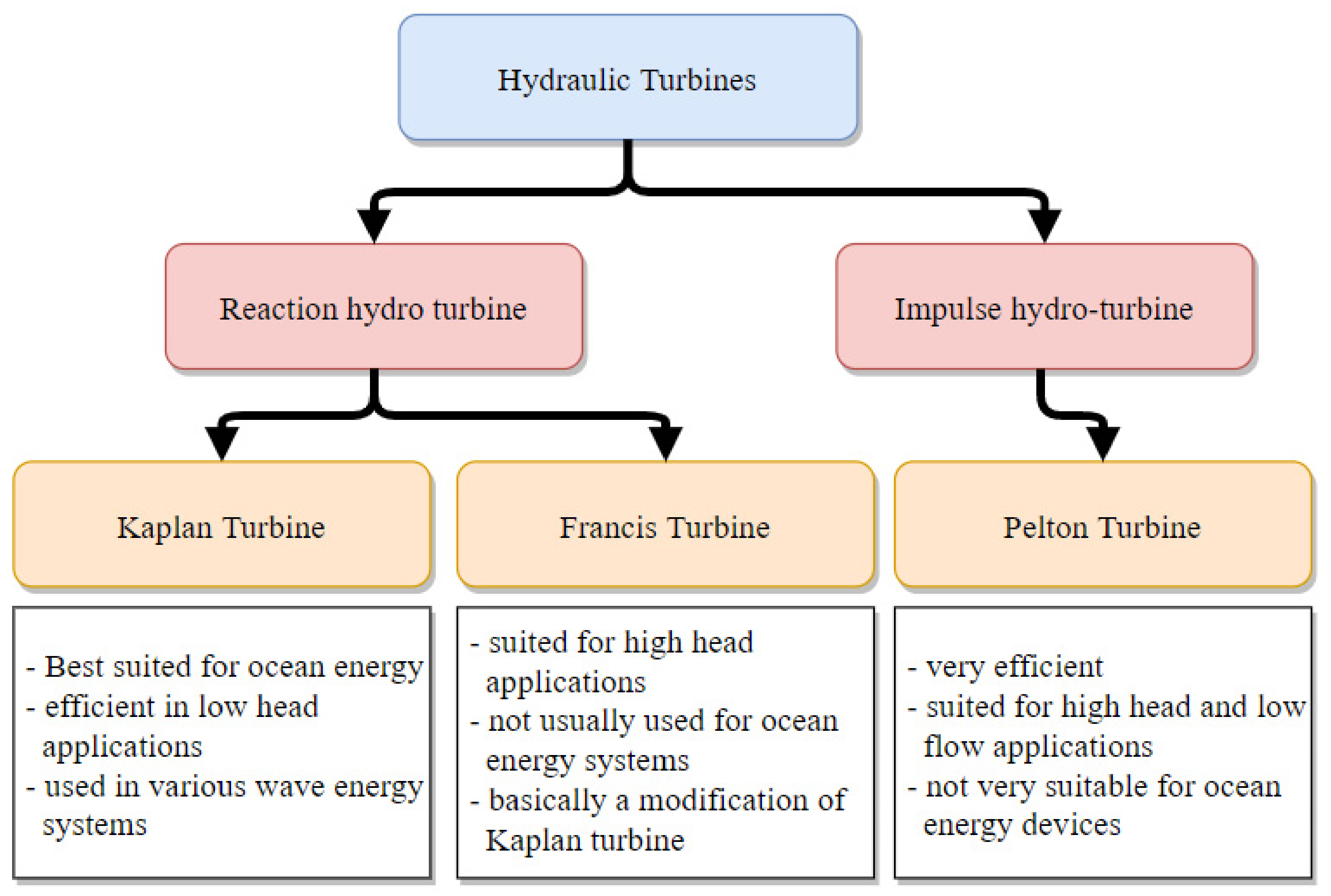
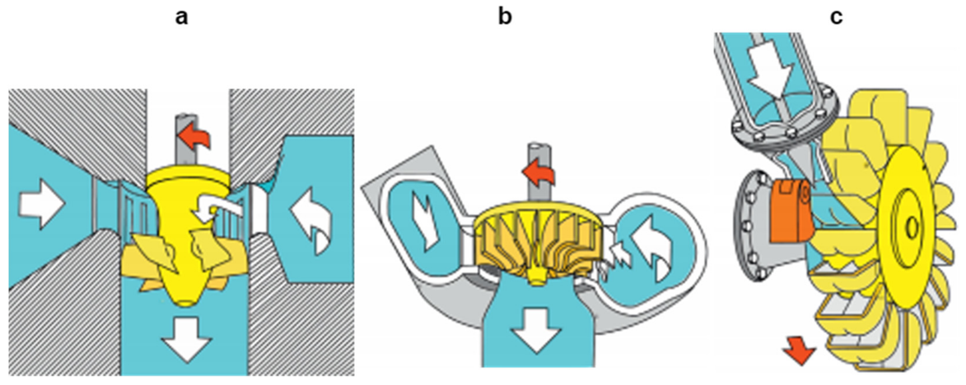
- Hydro-turbine technology is well entrenched, and has been in utilization for several decades in hydro-power generation. This technology has also been employed in several wave energy devices, as it can transform the energy in waves into the rotational inertia needed for electricity generation. The two major types are discussed below, and examples are depicted in Figure 7 and Figure 8.
- Hydraulic systems are another very commonly used mechanism to convert wave energy into mechanical power for electricity production. The slow oscillation caused by the waves in the power capture unit is converted into hydraulic pressure by means of hydraulic cylinders, and the hydraulic energy is then transformed into rotational energy for electrical generators by the aid of hydraulically driven rotors. The hydraulic systems contain special accumulators to supply a constant power output.
- The electrical generator forms a critical part of any wave energy conversion system, as it responsible for the conversion of the mechanical energy produced via power capture systems, and for its transformation into usable electrical energy. The use of rotational generators is very common in wave energy systems, though linear generators have been developed for some wave energy systems. Table 2 lists the various common types of rotational and linear generators which are put to use by different wave energy producers. The use of rotational generators is more prevalent in terms of offshore suitability, high energy efficiency and low cost, whereas linear generators require large systems that are costly and provide low energy production.
- It is identified with wave capture technology, which is better known as the working principle.
- Its orientation is based in part of the wavelength interacting with the wave capture device.
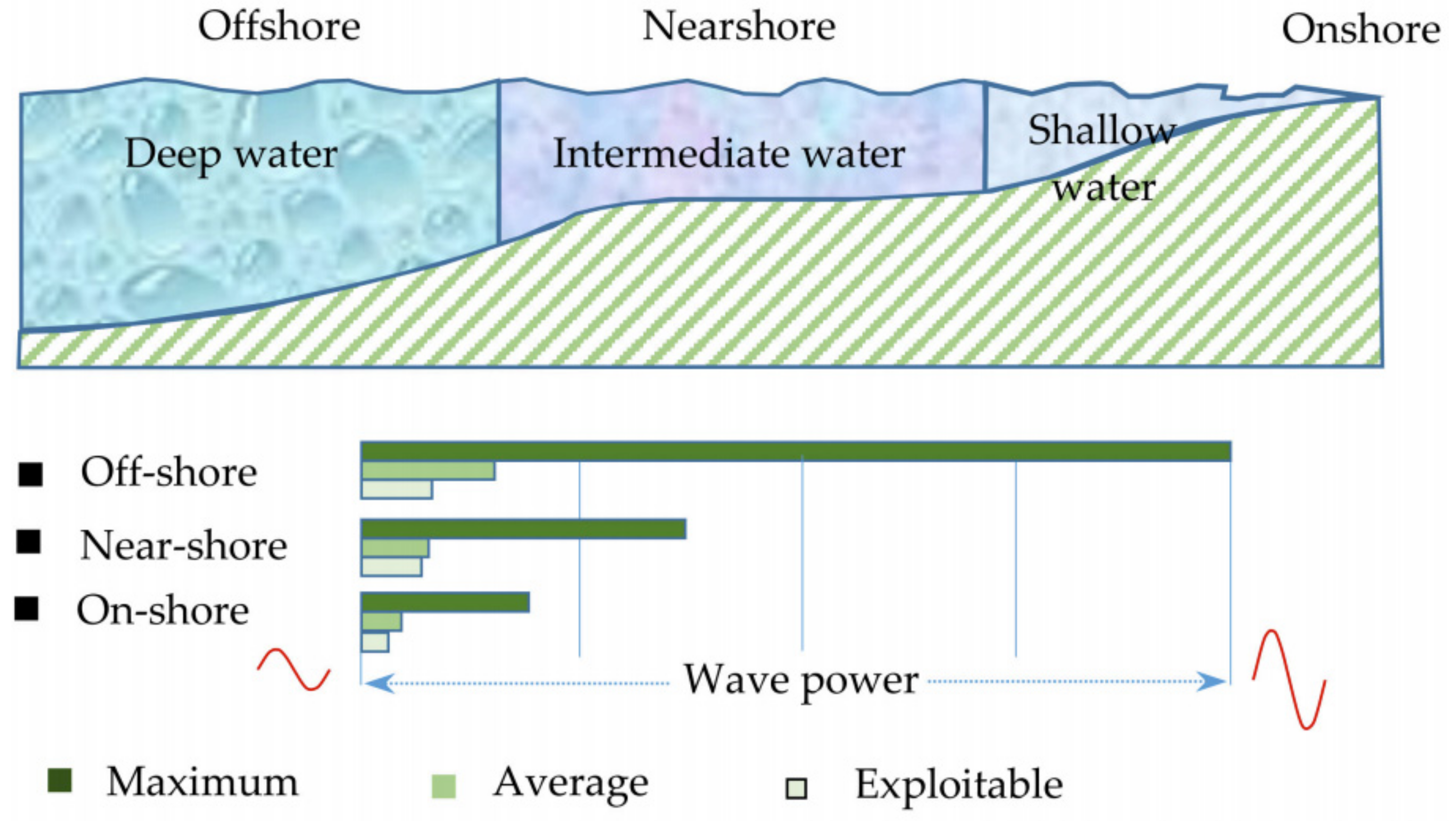
- It depends on the location of the device from the shore, or by the depth it is located at.
- Power take-off (PTO) technology.
2.1. Wave Energy Converter Based on PTO Systems
- hydraulic motor drive,
- hydro-turbine drive
- pneumatic turbine drive,
- direct electrical, and
- direct mechanical drive-based systems.
2.1.1. Hydro-Turbine-Based PTO System

| Year | WEC Name | Location and Deployed Place | Description | Output Power | Figure | Ref. |
|---|---|---|---|---|---|---|
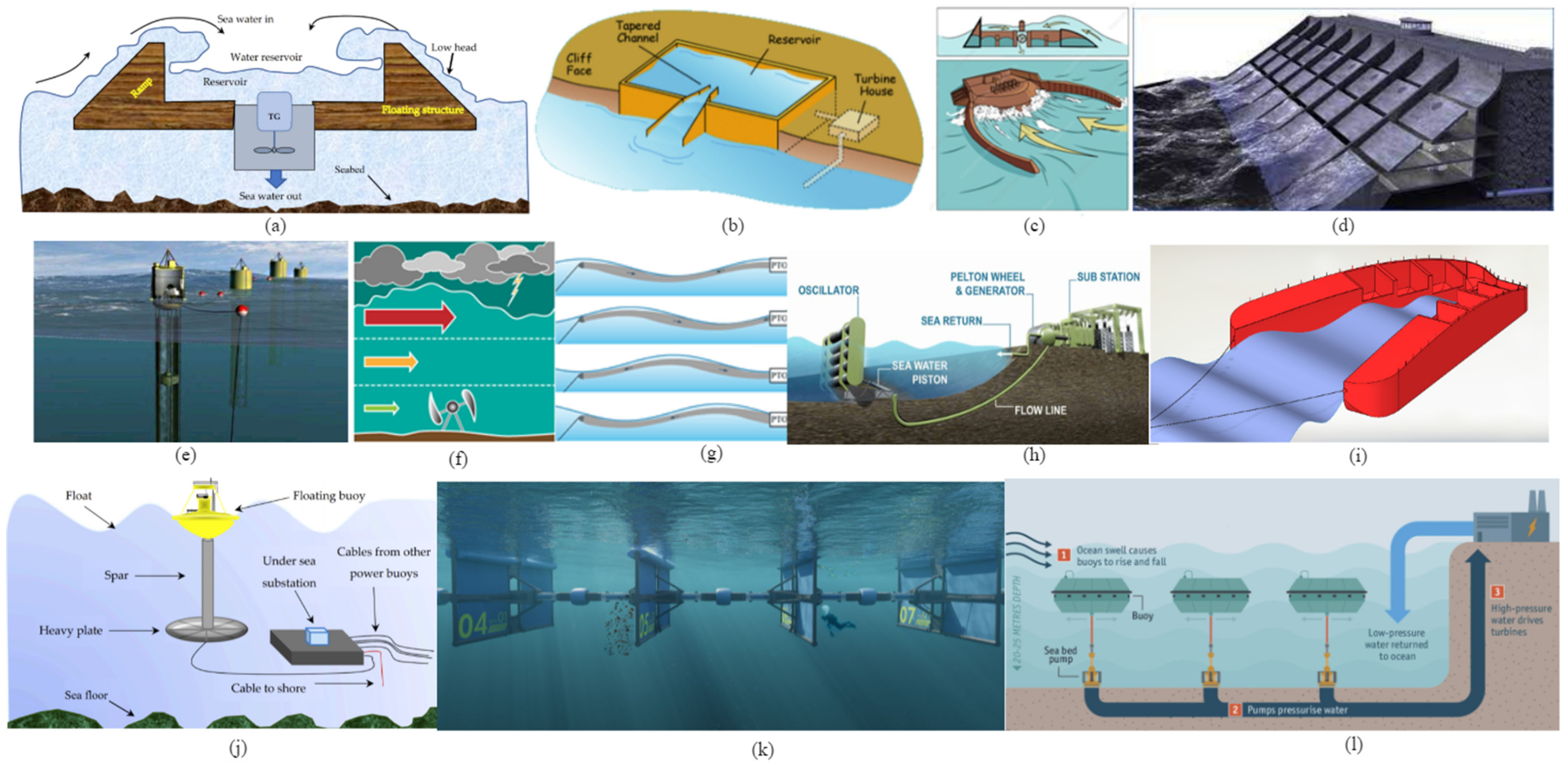
| 1985 | TAPCHAN | Onshore (Norway) | The TAPCHAN is an overtopping device in which the waves are directed through a ramped channel into a reservoir. From the reservoir the water travel through a hydro turbine back to sea, the hydro turbine produces usable electrical energy. | 350 kW | 11b | [37] |
| 2003 | Wave Dragon | Offshore (Denmark) | The wave dragon is a gigantic offshore floating WEC. The wave dragon uses the kinetic energy of waves to travel up a ramp into a basin where the potential energy of water is used to drive the hydro turbine. | 7 MW | 11c | [38] |
| 2003 | AquaBuoy | Offshore (Scotland, Canada, Ireland) | This device is a floating-point absorber system. The principle operation is similar to that of a hydraulic based point absorber but this device directly converts hydraulic pressure to electricity used a hydro generator. | 2.5 MW | 11e | [35] |
| 2004 | SSG | Onshore (Norway) | The SSG wave energy utilizes a 3-stage ramp system to convert the kinetic energy of waves to stored potential energy. The potential energy flow of water drives the hydro turbine to produce electricity. | 150 kW | 11d | [39] |
| 2006 | Cyclonical WEC | Offshore (USA) | Unlike the overtopping devices, this device is an underwater system that utilizes two hydrofoils rotating around a shaft driving an electric generator for electricity production. | 5 MW | 11f | [40] |
| 2008 | Anaconda | Offshore (UK) | Anaconda is essentially a closed rubber tube filled with water. The head is anchored to the sea bottom. Bulge waves are generated in the tube by pressure variation from external sea waves. These bulge waves are used to produce power through a power take of a device. | 1 MW | 11g | [41,42] |
| 2008 | Power Buoy | Offshore (Spain-2008, Scotland-2009, USA-2011, UK-2019) | Is an offshore two-body heaving wave energy system. The floating disc-shaped body reacts with the large horizontal damper plate to increase inertia by added mass of surrounding water. The heaving motion between two bodies is used to generate electricity by hydro PTO. | 40–150 kW | 11j | [38,43] |
| 2012 | Oyster | Nearshore (Scotland) | The oyster utilizes water pressure to drive a Pelton wheel to generate electric current. The technology behind is the huge flaps that oscillate creating water pressure via a piston-cylinder system. | 800 kW | 11h | [38,44] |
| 2013 | Wavepiston | Offshore (Denmark) | Wavepiston is a submerged offshore device also known as oscillating wave surge converter as it extracts kinetic energy available in orbitally moving water particles. The device has multiple working plates placed parallel and inline to incoming waves. The plates translate enabling a PTO. | 250 kW | 11k | [45] |
| 2014 | Vigor | Offshore (Sweden) | Vigor is an offshore semi-submerged floating device. It consists of a long rubber flat tube that resonates with the ocean waves. Water is propelled from the resonating waves to the hydro PTO which converts energy to electrical energy. | 12 MW | 11m | [46,47] |
| 2015 | CETO | Nearshore (Australia) | This device consists of submerged buoys that are connected to pumps. As the buoys experience wave disturbance, they expel fluid at high pressure through pumps. The pressurized water travels to the shore where it can be used to generate electricity. | 1 MW | 11l | [17,34] |
| 2017 | Crown | Offshore (China) | Crown is a circular overtopping device. It consists of a circular ramp that allows waves to come from all directly into the basin where the hydro operates to generate electrical current. | N/A | 11o | [48] |
| N/A | WaveCat | Offshore (Spain) | The device consists of two hulls like a catamaran. Unlike a catamaran, the hulls are converging or not parallel. The waves propagate between the hull and overtops in the reservoir. It goes back through a hydro turbine to produce power. | N/A | 11i | [32] |
| N/A | Waveplane | Nearshore (Denmark) | Waveplane is an overtopping device similar to the wave dragon design but it multiple chambers with hydro generators to convert the energy into smooth electrical output. | 200 kW | 11n | [40,49] |
| N/A | PowerGin | Offshore (US) | This device makes use of the overtopping technology of wave energy conversion to rotate a dual rotor system to achieve continuous rotary motion to generate electricity. The rotation is achieved via mini buckets lined up at an angle to produce rotation by mass of water. | 2 MW | 11p | [50] |


2.1.2. Direct Linear Electrical Output-Based PTO Systems

| Year | WEC Name | Location and Deployed Place | Description | Output Power | Figure | Ref. |
|---|---|---|---|---|---|---|
| 2002 | Lysekil | Offshore (Sweden) | This device is a simple wave energy conversion system that utilizes the heave motion of waves to generate electrical current. The oscillations caused by the waves enable a linear electric generator to operate. | 10 kW | 12a | [84] |
| 2004 | AWS | Offshore (Portugal) | This wave energy converter also utilizes a linear electric generator to produce electricity. The fully submerged device with an oscillating upper unit and bottom fixed lower part when incident to waves provide oscillations to the linear generator to activate. | 2 MW | 12b | [43] |
| 2008 | Oregon L10 | Offshore (USA) | This is a linear wave energy conversion technology that utilizes the concept of a point absorber with a saucer-shaped float. The PTO is submerged in an enclosed float and converts energy from the incident waves. | 10 kW | 12c | [65] |
| 2008 | DCEM | Nearshore (UK) | This system is similar to the previously designed system that comprises a buoy to capture the energy from the waves and convert it into electrical energy via an integrated linear generator. | 100 kW | 12d | [40] |
| 2011 | SeaRay | Offshore (USA) | The SeaRay consists of three rigid bodies. It is a non-symmetric point attenuator prototyped to function in heave, surge, and pitch modes of motion to produce electrical energy. | 1 MW | 12e | [85,86] |
| 2014 | UNDIGEN | Offshore (Spain) | Undigen was a project that involved two few industries and research centers to develop a two-body point absorber consisting of a direct drive PTO based on switched reluctance linear generator to produce electricity. | 200 kW | 12f | [87,88] |
| 2015 | Seabased | Offshore (Sweden) | This system makes use of 3-phase permanent magnet linear generator technology to produce usable energy. The generator is mounted on the sea bottom and enabled by a floating buoy on the surface via wave disturbance. | 10 kW | 12g | [40] |
| 2015 | SINN Power | Nearshore (Greece) | This company supplies wave energy conversion modules that float and follow the principle of heaving point absorbers. It has linear generators and can be connected in arrays to increase its capacity. | 3 kW | 12h | [87] |
| 2019 | StingRay | Offshore (USA) | The stingray is a 3-body wane energy converter. The Stingray technology uses different float shapes for the front and rear floats. The shapes drastically affect the movement with an incident wave to improve the power output of the device. | 500 kW | 12i | [88] |
| N/A | Brandl Generator | Offshore (Germany) | The brandl generator is a linear generator that uses the up or down movement of the shaft exerted by the waves to produce electrical energy. The energy can later be fed to the grid. | 1 kW | 12j | [89] |
2.1.3. Direct Mechanical Drive Systems
2.1.4. Hydraulic Motor System
2.1.5. Pneumatic Air Turbine-Based WEC Systems
| Year | WEC Name | Location and Deployed Place | Description | Output Power | Figure | Ref. |
|---|---|---|---|---|---|---|
| 1984 | Sanze shoreline gully | Onshore (Japan) | Naturally tapered channel that channel water through a gully forcing air out via air turbine producing electrical energy. This device was built primarily for the testing purpose of pneumatic turbines. | 40 kW | 15a | [177,178] |
| 1985 | Kaimei | Offshore (Japan) | Kaimei was built as a large articulated floating structure. The Kaimei consisted of an impulse turbine, wells turbine, and McCormick turbine for testing and development purposes. | 60 to 125 kW | 15b | [135] |
| 1987 | Multiresonant OWC | Onshore (Norway) | This design emerged from the harbour concept where a pair of walls protruding from the front absorber, thereby partially enclosing a rectangular basin. In the basin, the phenomenon of harbour resonance occurs. Air turbine is used as power take-off in this particular device. | 500 kW | 15c | [179] |
| 1990 | Bottom Standing OWC | Nearshore (India) | Bottom standing OWC is very similar to the Multiresonant OWC but the difference is the placement which in this case is nearshore. The waves travel in columns creating air pressure to drive the turbine. | 125 kW | 15d | [180] |
| 1991 | Vizhinjam | Onshore (India) | This is an oscillating water column plant that features a unidirectional impulse turbine. The output of the impulse turbine is directly connected to the grid supply. | 150 kW | 15e | [169,181] |
| 1992 | Sakata | Nearshore (Japan) | This was an oscillating water column device integrated into the breakwater to generate electricity. The energy harvester utilized a wells turbine to generate electrical energy. | 60 kW | 15f | [169] |
| 1995 | Osprey | Nearshore (UK) | One of the largest power energy nearshore bottom standing energy devices. The plant consisted of two wells turbine operating simultaneously to produce energy. Later it was destroyed in a natural disaster. | 1 MW | 15g | [169] |
| 2000 | Mighty Whale | Offshore (Japan) | The mighty whale uses several air chambers for oscillating water columns and mounted air turbines to generate air pressure created by the waves. Mighty Whale is a floating device. | 110 kW | 15h | [182] |
| 2001 | Limpet | Onshore (Scotland) | The Limpet is an onshore device consisting of a single air chamber that exhales and inhales air induced by the waves through a Wells turbine to produce power. | 500 kW | 15i | [121] |
| 2001 | Shoreline OWC | Onshore (China) | The plant was set up as a research and development program to study grid-connected wave energy systems. The device converts pneumatic power to electricity via a unidirectional turbine. | 100 kW | 15j | [169,183] |
| 2005 | Port Kembla OWC | Nearshore (Australia) | The power station was set up as an oscillating wave energy prototype. The project remained in operation till 2009. | 500 kW | 15k | [184] |
| 2005 | Pico | Nearshore (Portugal) | The device was built as a nearshore oscillating water column equipped with Wells turbine for electricity generation. The device stands on the sea-bottom. | 400 kW | 15l | [169] |
| 2008 | OE buoy | Offshore (Ireland) | This is a floating device converting ocean surge current to electricity through pneumatic turbines. | 1 MW | 15m | [169] |
| 2008 | Oceantec | Offshore (Spain) | This is an offshore floating device where the energy capture principle is inertial motion created by the gyroscopic system converting the wave energy to electricity. Another deployed in 2016—30 kW. | 500 kW | 15n | [40,185] |
| 2010 | Archimedes Wave Swing-iii | Offshore (Scotland) | The AWS-iii is the advanced version of previous AWS systems. The technology behind this is the multi-cell array of flexible absorbers. These absorbers convert wave power to pneumatic power for electricity generation. | 2.5 MW | 15o | [35] |
| 2011 | Mutriku | Nearshore (Spain) | This was the first nearshore multi turbine device to be installed in breakwater for energy harvesting using a Wells turbine. The device also marked the world’s first commercial project. | 300 kW | 15p | [14] |
| 2012 | Resonant Wave Energy Converter 3 | Onshore (Italy) | Unlike traditional OWC, the inner chamber of REWEC3 is connected to both the ocean wave and air chamber via the tiny vertical duct. This configuration greatly affects the performance of the device. | N/A | 15q | [186] |
| 2012 | Vert Labs | Offshore (Scotland) | This device transforms the kinetic energy of sea waves to pneumatic energy in the form of compressed air. The compressed air turbine is used to generate electricity. | 35 kW | 15r | [40] |
| 2013 | Oceanlinx | Offshore (Australia) | The oceanlinx was a singular OWC aimed at variable water depths and wave conditions. A prototype was launched, however, the deployment was not completed due to some incident. | 1 MW | 15s | [187] |
| 2013 | Offshore Wave Energy Ltd | Offshore (UK) | The device has a long duct where the waves enter and trap the air against the top of the duct. The narrow duct shape at the rear allows air to compress as waves travel forward. The compressed air turbine produces energy. | 12 MW | 15t | [40] |
| 2015 | Bombora | Nearshore (Australia) | The bombora utilizes large flexible membranes or diaphragms as an energy capture interface. As waves pass, the air pressurizes and travels through special ducts to air turbines for electricity production. | 1.5 MW | 15v | [188] |
| 2015 | LEANCON | Offshore (Denmark) | Is multi-chamber nearshore or offshore floating device. It has a V-shaped structure with 2 arms. The arms are equipped with cylindrical chambers which create pneumatic pressure deferential to incident waves. | 600 kW | 15w | [189] |
| 2016 | MARMOK-A-5 | Offshore (Spain) | This device is a vertical OWC utilizing a biradial turbine for energy production. | 30 kW | 15u | [190] |
| 2017 | Yongsoo | Nearshore (Korea) | The plant is equipped with an impulse turbine and is grid-connected. The device is under trial run. | 500 kW | 15x | [191] |
| 2019 | OE35 | Offshore (USA) | This concept is a technologically advanced version of the OWC utilizing an air flow turbine to generate power. The water column enclosed by the hull behaves like a piston to create airflow. | 500 kW | N/A | [192] |
| 2019 | Wave Swell | Nearshore (Australia) | Wave Swell was a project where the principle of natural blowhole was explored and the OWC energy converter was deployed for harnessing electrical energy. | 200 kW | 15y | [193] |
| N/A | MRC 1000 | Offshore (UK) | The device is under research and development phase. But no clear evidence about deployment for the device is provided. | 1 MW | N/A | [127] |

2.2. Hybrid Wave Systems
2.2.1. Wave and Wind
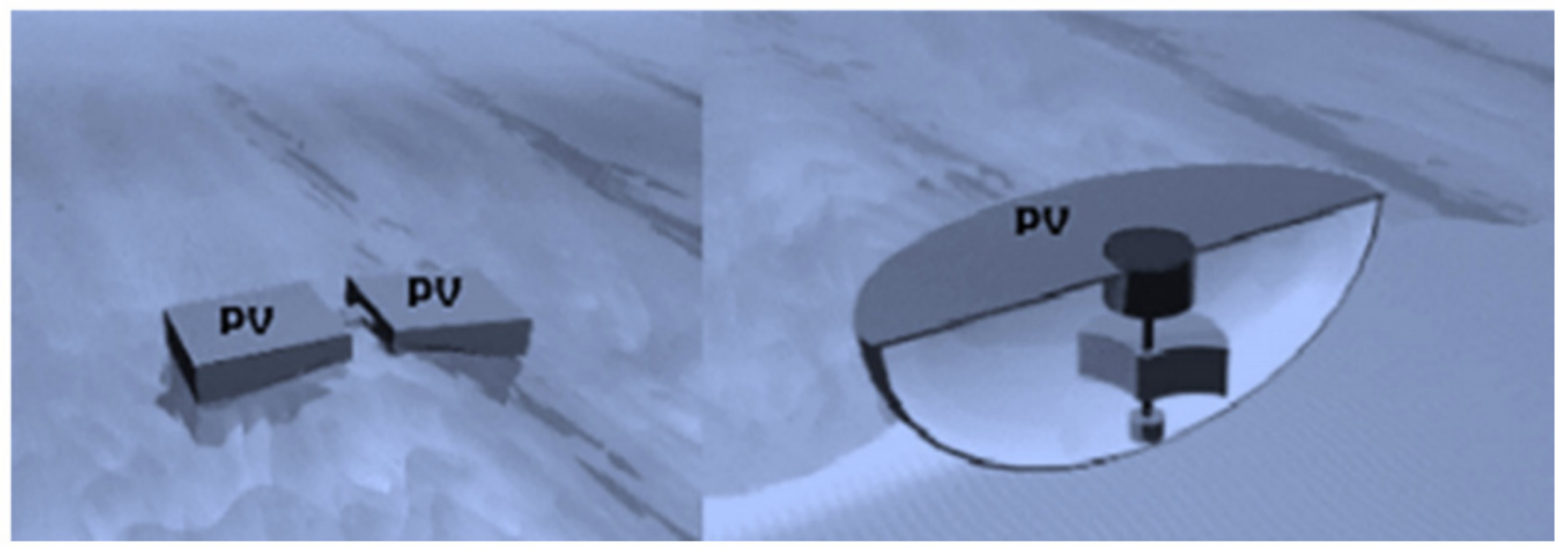
2.2.2. Wave and PV
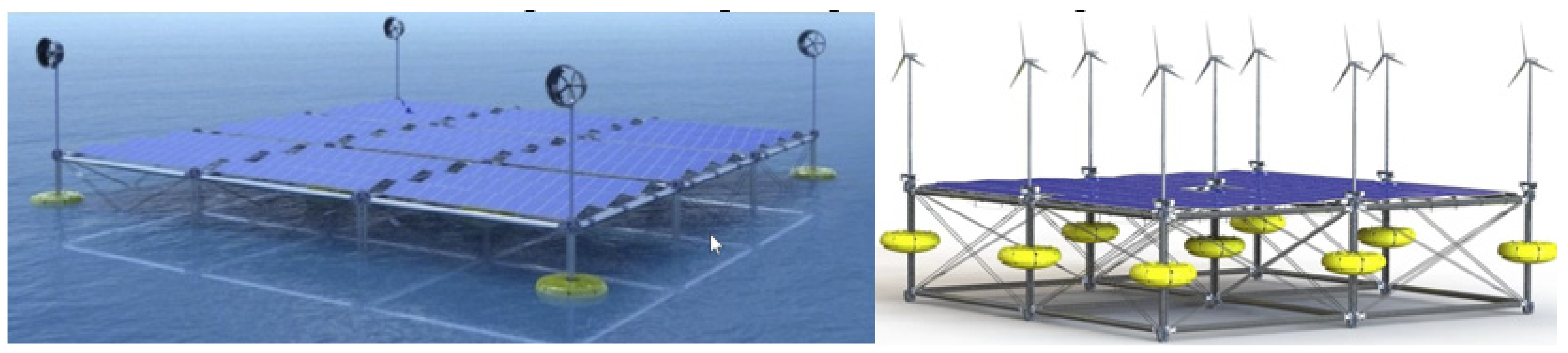
2.2.3. Wave, Wind, and Solar
2.3. Control Strategies
2.4. Numerical Modeling
- a force proportional to velocity (damper), and
- a force proportional to the displacement (spring).
- ω is the wave frequency,
- is the excitation force,
- m is the total inertia of the captor,
- A is the added mass,
- G is the hydrostatic spring stiffness,
- Kpto is the PTO mechanical spring,
- Km is the mooring spring stiffness,
- R is the radiation damping,
- Bpto is the PTO damping,
- Zi is the intrinsic impedance, and
- Zpto is the PTO impedance.
2.5. Damping Control
2.6. Reactive Control
2.7. Latching/Unlatching Control
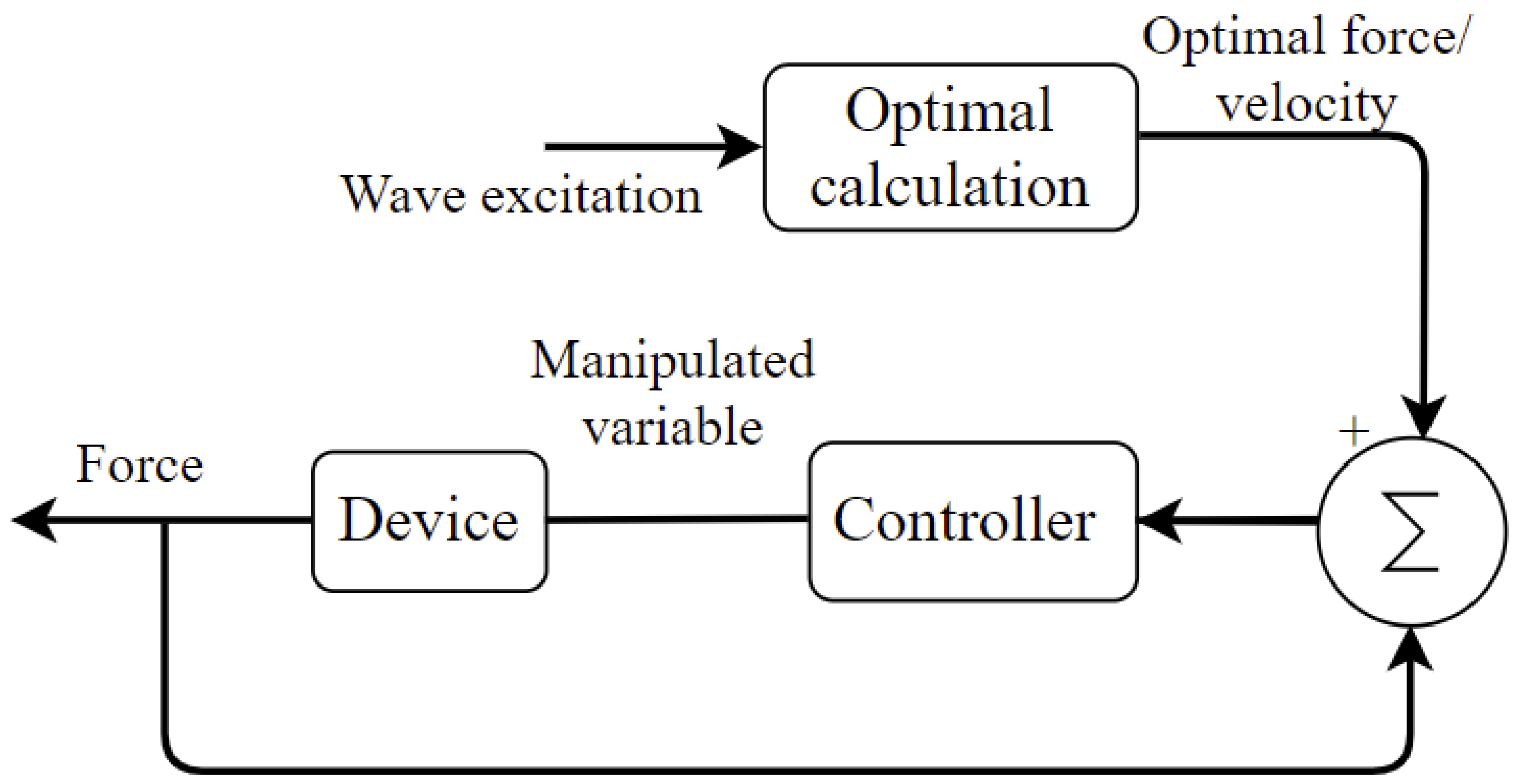
2.8. Model Predictive Control
2.9. Benefits and Challenges of WECs
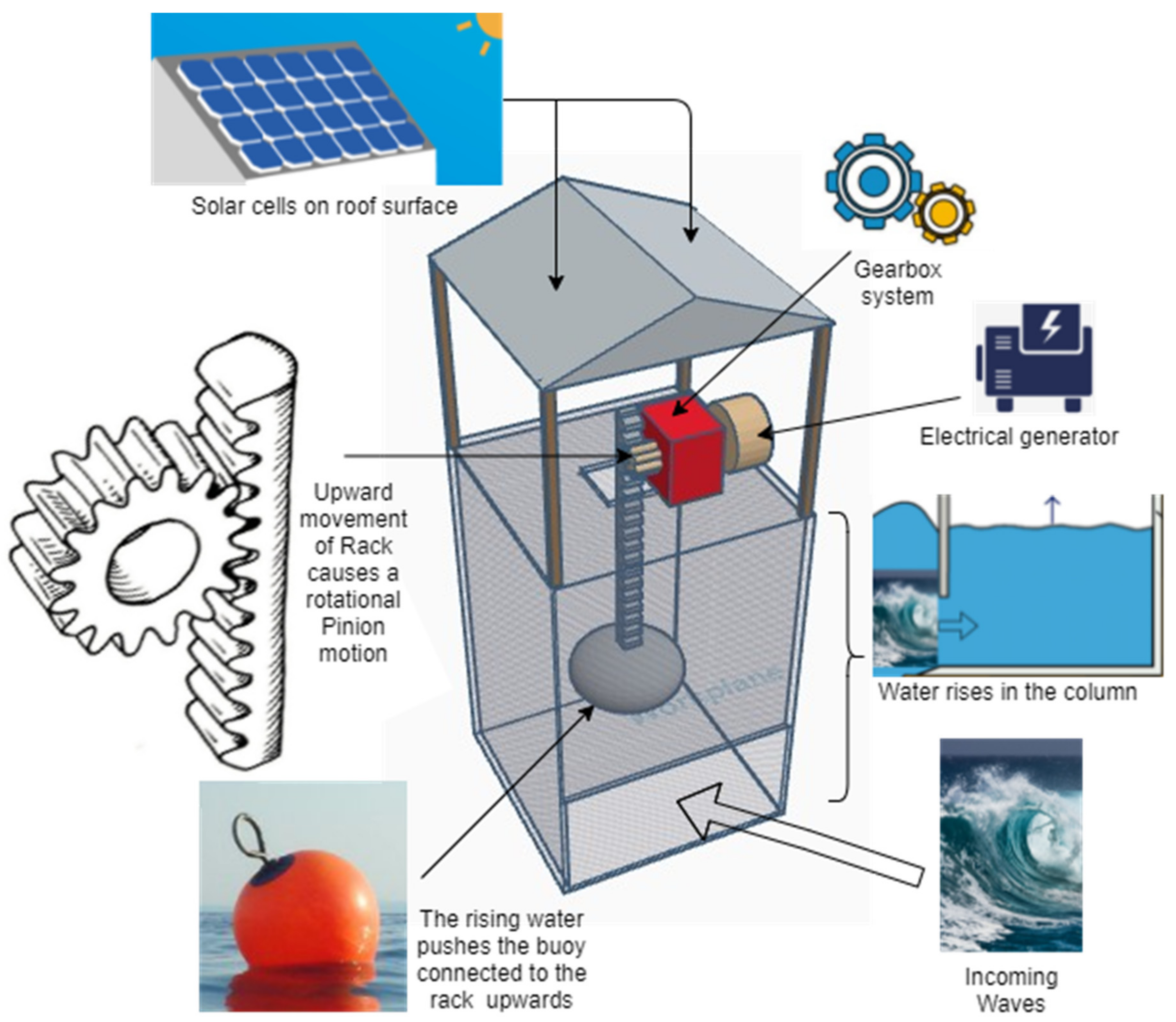
3. A Novel Hybrid Wave and Photon Energy (HWPE) Harvester
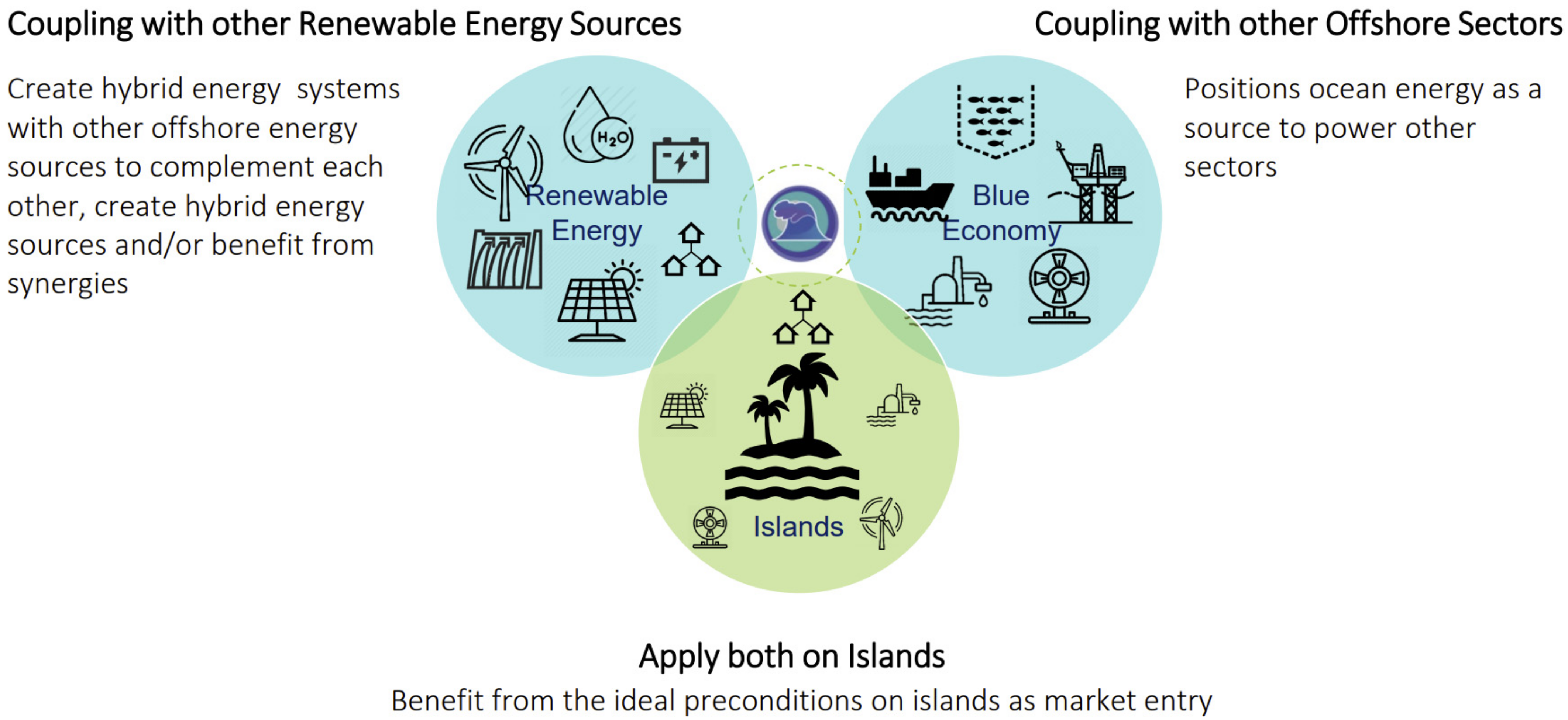
3.1. Opportunities for a Hybrid Wave and Photon Energy (HWPE) Harvester
3.2. Conceptual Design of the HWPE Harvester
3.3. Technology Support for the Design of the HWPE Harvester
3.3.1. Electro-Mechanical Components of Wave Energy Harvesters
3.3.2. Solar Cell Technologies
3.3.3. Energy Storage Systems
3.3.4. Power Transmission Systems
4. Challenges in Designing the HWPE Harvester
- Irregular wave amplitude, phase and trend, meaning that the optimized efficiency of a system over the spectrum of excitation frequencies is difficult to preserve.
- In the event of severe weather conditions, the structural load can be as high as 100 times the normal load.
- The coupling mechanism of slow and irregular waves (frequency ∼0.1 Hz and period ∼10 s) to electrical generators normally requires 50 to 60 Hz.
5. Potential Environmental Impacts of the HWPE Harvester
- Device Construction: Anchoring these devices may have an influence during installation. Pilings, concrete blocks, anchors, and chains are used to secure or tie several wave energy devices to the ocean floor. The dredging and scouring of the seabed may be required for site preparation in order to lay electrical wires. The number of devices deployed and the mooring mechanisms used would determine the degree of ocean-bottom disturbance.
- Environmental: Although wave energy does not emit any greenhouse gases or other pollutants when it generates power, emissions do occur throughout the life cycle of the technology. There are potential consequences of hydraulic fluid leakage and discharge into the surrounding waters for hydraulic rams, power trains, lubricating oils and fluids, and anti-corrosion and biofouling paints and coatings.
- Fishing Industry: Exclusion zones around offshore devices may have a negative influence on nearby fishing grounds. Anchor lines, tethers, and power cables prevent nets from being used, while floating devices can create protected areas that benefit some marine species and ecosystems by restricting access and fishing at the location. Fishing activity may grow just beyond the installation’s boundaries, as it does in maritime reserves.
- Marine Ecosystem: The floating constructions may be dangerous to marine mammals, or they may operate as obstacles to marine circulation and migration, altering the wildlife and vegetation on the seabed. The majority of offshore wave energy devices are tied directly to the seabed, and mooring lines might entangle certain species, particularly bigger whales. Seabirds may be enticed to utilize floating wave energy devices as temporary roosts.
- Navigational Hazards: Due of their low profile, WECs may be difficult to spot visually or using a ship’s radar, which might pose a navigational threat to shipping. WECs that are not lit at night or whose moorings break away during storms might have an influence on shipping. The water quality might also be harmed as a result of possible oil spills caused by increased boat activity in the region for maintenance and repair.
- Noise Pollution: The continual noise from wave capture devices, particularly in harsh weather, may have an effect on whales and dolphins that hunt via echolocation. The operational noise levels of shoreline and nearshore devices may be a nuisance locally on the beach or shoreline. When fully functioning, however, any device-generated noise will most likely be drowned out by the natural sounds of the wind and waves.
- Recreational Activities: Offshore and nearshore floating devices might have an influence on recreational swimming and water sports in the area. Sub-aqua diving and water skiing may benefit from the protection provided by these devices, while sailing and wind surfing may suffer. Furthermore, while nearshore devices may only require a few hundred yards of water depth, there is an aesthetic impact of large-scale installations on tourism.
- Sedimentary Flow: Onshore and nearshore wave energy facilities—such as device platforms, anchors, and cables—may alter the flow of water and sands directly surrounding the structures. Sediment transport, coastal erosion, and the deposition of coarse sediments such as pebbles or boulders will all be affected by changes in water velocity. Sediment will be deposited more readily if water currents are slowed or limited.
6. Conclusions
Author Contributions
Funding
Institutional Review Board Statement
Informed Consent Statement
Data Availability Statement
Acknowledgments
Conflicts of Interest
References
- IRENA. Global Renewables Outlook: Energy Transformation 2050; IRENA: Abu Dhabi, United Arab Emitares, 2020. [Google Scholar]
- Ritchie, H.; Roser, M. Electricity Mix. Our World in Data. 2020. Available online: https://ourworldindata.org/energy (accessed on 21 November 2021).
- Renewables 2020—Global Status Report, REN 21. Available online: https://www.ren21.net/gsr-2020/ (accessed on 11 November 2021).
- Farrok, O.; Ahmed, K.; Tahlil, A.D.; Farah, M.M.; Kiran, M.R.; Islam, M. Electrical power generation from the oceanic wave for sustainable advancement in renewable energy technologies. Sustainability 2020, 12, 2178. [Google Scholar] [CrossRef] [Green Version]
- Prakash, S.S.; Mamun, K.A.; Islam, F.R.; Mudliar, R.; Pau’u, C.; Kolivuso, M.; Cadralala, S. Wave energy converter: A review of wave energy conversion technology. In Proceedings of the 2016 3rd Asia-Pacific World Congress on Computer Science and Engineering (APWC on CSE), Nadi, Fiji, 5–6 December 2016; IEEE: Piscataway, NJ, USA, 2016; pp. 71–77. [Google Scholar]
- Mofor, L.; Goldsmith, J.; Jones, F. Ocean Energy: Technology Readiness, Patents, Deployment Status and Outlook; IRENA: Abu Dhabi, United Arab Emirates, 2014. [Google Scholar]
- Liu, C.; Yu, H.; Hu, M.; Liu, Q.; Zhou, S.; Huang, L. Research on a permanent magnet tubular linear generator for direct drive wave energy conversion. IET Renew. Power Gener. 2014, 8, 281–288. [Google Scholar] [CrossRef]
- Tom, N.; Yeung, R.W. Experimental confirmation of nonlinear-model-predictive control applied offline to a permanent magnet linear generator for ocean-wave energy conversion. IEEE J. Ocean. Eng. 2015, 41, 281–295. [Google Scholar]
- Chozas, J.F. Technical and Non-Technical Issues Towards the Commercialisation of Wave Energy Converters; River Publishers: Gistrup, Denmark, 2013. [Google Scholar]
- Masuda, Y.; Yamazaki, T.; Outa, Y.; McCormick, M.E. The backward bend duct buoy-an improved floating type wave power device. In Proceedings of the OCEANS’88.‘A Partnership of Marine Interests’, Baltimore, MD, USA, 31 October–2 November 1988; IEEE: Piscataway, NJ, USA, 1988; pp. 1067–1072. [Google Scholar]
- Pontes, M.T. Assessing the European wave energy resource. J. Offshore Mech. Arct. Eng. 1998, 120, 226–231. [Google Scholar] [CrossRef]
- Folley, M.; Curran, R.; Whittaker, T. Comparison of LIMPET contra-rotating wells turbine with theoretical and model test predictions. Ocean. Eng. 2006, 33, 1056–1069. [Google Scholar] [CrossRef]
- Sheng, W. Wave energy conversion and hydrodynamics modelling technologies: A review. Renew. Sustain. Energy Rev. 2019, 109, 482–498. [Google Scholar] [CrossRef]
- Torre-Enciso, Y.; Ortubia, I.; De Aguileta, L.L.; Marqués, J. Mutriku wave power plant: From the thinking out to the reality. In Proceedings of the 8th European Wave and Tidal Energy Conference, Uppsala, Sweden, 7–10 September 2009; Volume 710, pp. 319–329. [Google Scholar]
- Rhinefrank, K.; Agamloh, E.B.; von Jouanne, A.; Wallace, A.K.; Prudell, J.; Kimble, K.; Aills, J.; Schmidt, E.; Chan, P.; Sweeny, B.; et al. Novel ocean energy permanent magnet linear generator buoy. Renew. Energy 2006, 31, 1279–1298. [Google Scholar] [CrossRef]
- Zhou, T. Damping Profile Research for Corpower Ocean’s Wave Energy Converter; Kth Royal Institute of Technology: Stockholm, Sweden, 2016. [Google Scholar]
- Neshat, M.; Mirjalili, S.; Sergiienko, N.Y.; Esmaeilzadeh, S.; Amini, E.; Heydari, A.; Garcia, D.A. Layout optimisation of offshore wave energy converters using a novel multi-swarm cooperative algorithm with backtracking strategy: A case study from coasts of Australia. Energy 2022, 239, 122463. [Google Scholar]
- Draper, M. More than just a ripple: Ocean power technologies sets its sights high. Refocus 2006, 7, 54–56. [Google Scholar] [CrossRef]
- Henderson, R. Design, simulation, and testing of a novel hydraulic power take-off system for the Pelamis wave energy converter. Renew. Energy 2006, 31, 271–283. [Google Scholar] [CrossRef]
- Yemm, R.; Pizer, D.; Retzler, C.; Henderson, R. Pelamis: Experience from concept to connection. Philos. Trans. R. Soc. A Math. Phys. Eng. Sci. 2012, 370, 365–380. [Google Scholar] [CrossRef] [Green Version]
- Henry, A.; Doherty, K.; Cameron, L.; Whittaker, T.; Doherty, R. Advances in the Design of the Oyster Wave Energy Converter; RINA Marine and Offshore Renewable Energy: London, UK, 2010. [Google Scholar]
- Whittaker, T.; Folley, M. Nearshore oscillating wave surge converters and the development of Oyster. Philos. Trans. R. Soc. A Math. Phys. Eng. Sci. 2012, 370, 345–364. [Google Scholar] [CrossRef] [PubMed] [Green Version]
- Mehlum, E. Tapchan. In Hydrodynamics of Ocean Wave-Energy Utilization; Springer: Berlin/Heidelberg, Germany, 1986; pp. 51–55. [Google Scholar]
- Kofoed, J.P.; Frigaard, P.; Friis-Madsen, E.; Sørensen, H.C. Prototype testing of the wave energy converter wave dragon. Renew. Energy 2006, 31, 181–189. [Google Scholar] [CrossRef] [Green Version]
- Drew, B.; Plummer, A.R.; Sahinkaya, M.N. A review of wave energy converter technology. Proc. Inst. Mech. Eng. Part A J. Power Energy 2009, 223, 887–902. [Google Scholar] [CrossRef] [Green Version]
- Cornett, A.; Toupin, M.; Baker, S.; Piche, S.; Nistor, I. Appraisal of IEC standards for wave and tidal energy resource assessment. In Proceedings of the International Conference on Ocean Energy (ICOE), Halifax, NS, Canada, 4–6 November 2014; pp. 3–9. [Google Scholar]
- Neary, V.S.; Lawson, M.; Previsic, M.; Copping, A.; Hallett, K.C.; Labonte, A.; Rieks, J.; Murray, D. Methodology for Design and Economic Analysis of Marine Energy Conversion (MEC) Technologies; Sandia National Lab.(SNL-NM): Albuquerque, NM, USA, 2014. [Google Scholar]
- Bull, D. An improved understanding of the natural resonances of moonpools contained within floating rigid-bodies: Theory and application to oscillating water column devices. Ocean. Eng. 2015, 108, 799–812. [Google Scholar] [CrossRef] [Green Version]
- Sheng, W.; Lewis, A. Power takeoff optimization for maximizing energy conversion of wave-activated bodies. IEEE J. Ocean. Eng. 2016, 41, 529–540. [Google Scholar] [CrossRef]
- Parmeggiani, S.; Chozas, J.F.; Pecher, A.; Friis-Madsen, E.; Sørensen, H.C.; Kofoed, J.P. Performance assessment of the wave dragon wave energy converter based on the EquiMar methodology. In Proceedings of the 9th Ewtec European Wave and Tidal Conference, Southampton, UK, 5–9 September 2011; University of Southampton: Southampton, UK, 2011. [Google Scholar]
- Polinder, H.; Scuotto, M. Wave energy converters and their impact on power systems. In Proceedings of the 2005 International Conference on Future Power Systems, Amsterdam, The Netherlands, 18 November 2005; IEEE: Piscataway, NJ, USA, 2005. [Google Scholar]
- Fernandez, H.; Iglesias, G.; Carballo, R.; Castro, A.; Fraguela, J.A.; Taveira-Pinto, F.; Sanchez, M. The new wave energy converter WaveCat: Concept and laboratory tests. Mar. Struct. 2012, 29, 58–70. [Google Scholar] [CrossRef]
- Rafiee, A.; Fiévez, J. Numerical prediction of extreme loads on the CETO wave energy converter. In Proceedings of the 11th European Wave and Tidal Energy Conference, Nantes, France, 6–11 September 2015. [Google Scholar]
- Mann, L.D. Application of ocean observations & analysis: The CETO wave energy project. In Operational Oceanography in the 21st Century; Springer: Dordrecht, The Netherlands, 2011; pp. 721–729. [Google Scholar]
- Fadaeenejad, M.; Shamsipour, R.; Rokni, S.D.; Gomes, C. New approaches in harnessing wave energy: With special attention to small islands. Renew. Sustain. Energy Rev. 2014, 29, 345–354. [Google Scholar] [CrossRef]
- Dhanak, M.R.; Xiros, N.I. (Eds.) Springer Handbook of Ocean Engineering; Springer: Cham, Switzerland, 2016. [Google Scholar]
- Poullikkas, A. Technology prospects of wave power systems. Electron. J. Energy Environ. 2014, 2, 47–69. [Google Scholar]
- Lin, Y.; Bao, J.; Liu, H.; Li, W.; Tu, L.; Zhang, D. Review of hydraulic transmission technologies for wave power generation. Renew. Sustain. Energy Rev. 2015, 50, 194–203. [Google Scholar] [CrossRef]
- Margheritini, L.; Vicinanza, D.; Frigaard, P. SSG wave energy converter: Design, reliability and hydraulic performance of an innovative overtopping device. Renew. Energy 2009, 34, 1371–1380. [Google Scholar] [CrossRef]
- Joubert, J.R.; van Niekerk, J.L.; Reinecke, J.; Meyer, I. Wave Energy Converters (WECs); CRSES: Matieland, South Africa, 2013. [Google Scholar]
- Heller, V.; Chaplin, J.R.; Farley, F.J.M.; Hann, M.R.; Hearn, G.E. Physical model tests of the anaconda wave energy converter. In Proceedings of the 1st IAHR European Congress, Edinburgh, UK, 4–6 May 2010. [Google Scholar]
- Chaplin, J.R.; Heller, V.; Farley, F.J.M.; Hearn, G.E.; Rainey, R.C.T. Laboratory testing the Anaconda. Philos. Trans. R. Soc. A Math. Phys. Eng. Sci. 2012, 370, 403–424. [Google Scholar] [CrossRef] [PubMed]
- Antonio, F.D.O. Wave energy utilization: A review of the technologies. Renew. Sustain. Energy Rev. 2010, 14, 899–918. [Google Scholar]
- Cameron, L.; Doherty, R.; Henry, A.; Doherty, K.; Van’t Hoff, J.; Kaye, D.; Naylor, D.; Bourdier, S.; Whittaker, T. Design of the next generation of the Oyster wave energy converter. In Proceedings of the 3rd International Conference on Ocean Energy, Bilbao, Spain, 6–8 October 2010; Volume 6, p. 1e12. [Google Scholar]
- Read, R.; Bingham, H. Time-and frequency-domain comparisons of the wavepiston wave energy converter. In Proceedings of the 33rd International Workshop on Water Waves and Floating Bodies (IWWWFB), Guidel-Plages, France, 4–7 April 2018. [Google Scholar]
- Gürsel, K.T.; Ünsalan, D.; Neşer, G.; Taner, M.; Altunsaray, E.; Önal, M. A Technological Assessment Of the Wave Energy Converter. Sci. Bull. Nav. Acad. 2016, 19, 408–417. [Google Scholar] [CrossRef]
- Rodríguez-Muñoz, A.; Moreno-Jiménez, B.; Sanz-Vergel, A.I. Reciprocal relations between workplace bullying, anxiety, and vigor: A two-wave longitudinal study. Anxiety Stress Coping 2015, 28, 514–530. [Google Scholar] [CrossRef] [Green Version]
- Liu, Z.; Shi, H.; Cui, Y.; Kim, K. Experimental study on overtopping performance of a circular ramp wave energy converter. Renew. Energy 2017, 104, 163–176. [Google Scholar] [CrossRef]
- Frigaard, P.; Trewers, A.; Kofoed, J.P.; Margheritini, L. Conceptual Design of Wave Plane; Department of Civil Engineering, Aalborg University: Aalborg, Denmark, 2008. [Google Scholar]
- Ventures, P.E. Task-2.1. 2017. Available online: 1-EPRI-Wave-Energy-Tech-Assessment-2009.pdf (accessed on 11 November 2021).
- Wave Dragon Wave Energy Converter Illustration. Available online: https://www.sciencephoto.com/media/1003747/view/wave-dragon-wave-energy-converter-illustration (accessed on 12 November 2021).
- Vicinanza, D.; Margheritini, L.; Kofoed, J.P.; Buccino, M. The SSG wave energy converter: Performance, status and recent developments. Energies 2012, 5, 193–226. [Google Scholar] [CrossRef] [Green Version]
- Wave Energy Aquabuoy 20 Wave Power Generator. Available online: https://www.google.com/url?sa=i&url=https%3A%2F%2Finhabitat.com%2Fwave-energy-aquabuoy-20-wave-power-generator%2Faquabuoy-finavera-wave-power-wave-energy-renewables%2F&psig=AOvVaw2IcC612VgxbEVS5ZBS80xq&ust=1622883641634000&source=images&cd=vfe&ved=0CA0QjhxqFwoTCPCp28XR_fACFQAAAAAdAAAAABAD (accessed on 13 November 2021).
- CycWEC Design Features. Available online: https://atargis.com/CycWEC.html (accessed on 21 November 2021).
- Anaconda Wave Energy Converter Concept. Available online: https://energy.soton.ac.uk/anaconda-wave-energy-converter-concept/ (accessed on 21 November 2021).
- Renzi, E.; Doherty, K.; Henry, A.; Dias, F. How does Oyster work? The simple interpretation of Oyster mathematics. Eur. J. Mech. -B/Fluids 2014, 47, 124–131. [Google Scholar] [CrossRef] [Green Version]
- Allen, J.; Iglesias, G.; Greaves, D.; Miles, J. Physical Modelling of the Effect on the Wave Field of the WaveCat Wave Energy Converter. J. Mar. Sci. Eng. 2021, 9, 309. [Google Scholar] [CrossRef]
- Wavepiston Launches Crowfunding Campaign. Available online: https://www.offshore-energy.biz/wavepiston-launches-crowdfunding-campaign/ (accessed on 21 November 2021).
- Science and Technology. Available online: https://www.economist.com/science-and-technology/2015/03/12/looks-swell (accessed on 21 November 2021).
- Vigor Wave Energy. Available online: https://www.cadcraft.com/sv/uppdragsgivare/vigor-wave-energy/ (accessed on 21 November 2021).
- WavePlane. Available online: http://www.waveplane.com/ (accessed on 21 November 2021).
- Ocean Wave Energy. Available online: https://www.slideshare.net/Funk98/ocean-wave-energy (accessed on 21 November 2021).
- Mueller, M.; Baker, N.J. A low speed reciprocating permanent magnet generator for direct drive wave energy converters. In Proceedings of the International Conference on Power Electronics Machines and Drives, Bath, UK, 16–18 April 2002. [Google Scholar]
- Polinder, H.; Mecrow, B.C.; Jack, A.G.; Dickinson, P.G.; Mueller, M.A. Conventional and TFPM linear generators for direct-drive wave energy conversion. IEEE Trans. Energy Convers. 2005, 20, 260–267. [Google Scholar] [CrossRef]
- Brekken, T.K.; Von Jouanne, A.; Han, H.Y. Ocean wave energy overview and research at Oregon State University. In Proceedings of the 2009 IEEE Power Electronics and Machines in Wind Applications, Lincoln, NE, USA, 24–26 June 2009; IEEE: Piscataway, NJ, USA, 2009; pp. 1–7. [Google Scholar]
- Elwood, D.; Yim, S.C.; Prudell, J.; Stillinger, C.; Von Jouanne, A.; Brekken, T.; Brown, A.; Paasch, R. Design, construction, and ocean testing of a taut-moored dual-body wave energy converter with a linear generator power take-off. Renew. Energy 2010, 35, 348–354. [Google Scholar] [CrossRef]
- Prudell, J.; Stoddard, M.; Brekken, T.K.; von Jouanne, A. A novel permanent magnet tubular linear generator for ocean wave energy. In Proceedings of the 2009 IEEE Energy Conversion Congress and Exposition, San Jose, CA, USA, 20–24 September 2009; IEEE: Piscataway, NJ, USA, 2009; pp. 3641–3646. [Google Scholar]
- Danielsson, O.; Leijon, M.; Thorburn, K.; Eriksson, M.; Bernhoff, H. A direct drive wave energy converter: Simulations and experiments. In Proceedings of the International Conference on Offshore Mechanics and Arctic Engineering, Halkidiki, Greece, 12–17 June 2005; Volume 41960, pp. 797–801. [Google Scholar]
- Hong, Y.; Hultman, E.; Castellucci, V.; Ekergård, B.; Sjökvist, L.; Elamalayil Soman, D.; Krishna, R.; Haikonen, K.; Baudoin, A.; Lindblad, L.; et al. Status update of the wave energy research at Uppsala University. In Proceedings of the 10th European Wave and Tidal Conference (EWTEC), Aalborg, Denmark, 2–5 September 2013. [Google Scholar]
- Stålberg, M.; Waters, R.; Eriksson, M.; Danielsson, O.; Thorburn, K.; Bernhoff, H.; Leijon, M. Full-Scale Testing of PM Linear Generator for Point Absorber WEC. In Proceedings of the 6th EWTEC Conference, Glasgow, UK, 28 August–3 September 2005. [Google Scholar]
- Waters, R. Energy from Ocean Waves: Full Scale Experimental Verification of a Wave Energy Converter. Ph.D. Thesis, Universitets Biblioteket, Stockholm, Sweden, 2008. [Google Scholar]
- Waters, R.; Stålberg, M.; Danielsson, O.; Svensson, O.; Gustafsson, S.; Strömstedt, E.; Eriksson, M.; Sundberg, J.; Leijon, M. Experimental results from sea trials of an offshore wave energy system. Appl. Phys. Lett. 2007, 90, 034105. [Google Scholar] [CrossRef]
- LiVecchi, A.; Copping, A.; Jenne, D.; Gorton, A.; Preus, R.; Gill, G.; Robichaud, R.; Green, R.; Geerlofs, S.; Gore, S.; et al. Powering the Blue Economy; Exploring Opportunities for Marine Renewable Energy in Maritime Markets; US Department of Energy, Office of Energy Efficiency and Renewable Energy: Washington, DC, USA, 2019; 207p.
- Castellucci, V.; Strömstedt, E. Sea level variability in the Swedish Exclusive Economic Zone and adjacent seawaters: Influence on a point absorbing wave energy converter. Ocean Sci. 2019, 15, 1517–1529. [Google Scholar] [CrossRef] [Green Version]
- Two Teams Secure Scottish Funding to Seek Wave Energy Savings. Available online: https://www.theconstructionindex.co.uk/news/view/two-teams-secure-scottish-funding-to-seek-wave-energy-savings (accessed on 21 November 2021).
- Kassem, A.M.; Besheer, A.H.; Atawi, I.E. Kalmen estimator as a robust solution for output power maximization of wave energy converter. IEEJ Trans. Electr. Electron. Eng. 2015, 10, 390–395. [Google Scholar] [CrossRef]
- Renewable Energy Amog Wave Energy Device. Available online: https://amog.consulting/renewable-energy/amog-wave-energy-device (accessed on 21 November 2021).
- SeaRAY Autonomous Offshore Power System for Resident Vehicles, Sensor Packages, and Operating Equipment (50 Watts to 20 kWs). Available online: https://cpower.co/searay/ (accessed on 21 November 2021).
- Undigen. Available online: https://sectormaritimo.es/undigen (accessed on 21 November 2021).
- Seabased Signs Deal to install 100 mw Wave Energy Park in Ghana. Available online: https://www.hydroreview.com/world-regions/seabased-signs-deal-to-install-100-mw-wave-energy-park-in-ghana/#gref (accessed on 21 November 2021).
- SINN Power Wave Energy Converter Modules. Available online: https://www.sinnpower.com/projects (accessed on 21 November 2021).
- Dnv Gl Issues Statement of Feasibility for Stingray Wave Energy Devide. Available online: https://www.windpowerengineering.com/dnv-gl-issues-statement-of-feasibility-for-stingray-wave-energy-device/ (accessed on 21 November 2021).
- Saubere Energie aus Meereswellen. Available online: http://brandlmotor.de/download/BrandlGenerator_InfoFlyer (accessed on 21 November 2021).
- Leijon, M.; Boström, C.; Danielsson, O.; Gustafsson, S.; Haikonen, K.; Langhamer, O.; Strömstedt, E.; Stålberg, M.; Sundberg, J.; Svensson, O.; et al. Wave energy from the North Sea: Experiences from the Lysekil research site. Surv. Geophys. 2008, 29, 221–240. [Google Scholar] [CrossRef] [Green Version]
- So, R.; Michelen, C.; Bosma, B.; Lenee-Bluhm, P.; Brekken, T.K. Statistical analysis of a 1: 7 scale field test wave energy converter using WEC-sim. IEEE Trans. Sustain. Energy 2017, 8, 1118–1126. [Google Scholar] [CrossRef]
- Koca, K.; Kortenhaus, A.; Oumeraci, H.; Zanuttigh, B.; Angelelli, E.; Cantu, M.; Suffredini, R.; Franceschi, G. Recent advances in the development of wave energy converters. In Proceedings of the 9th European Wave and Tidal Energy Conference (EWTEC), Southampton, UK, 5–9 September 2013; pp. 2–5. [Google Scholar]
- Mattiazzo, G. State of the art and perspectives of wave energy in the Mediterranean sea: Backstage of ISWEC. Front. Energy Res. 2019, 7, 114. [Google Scholar] [CrossRef] [Green Version]
- Lawson, M.; Yu, Y.H.; Nelessen, A.; Ruehl, K.; Michelen, C. Implementing Nonlinear Buoyancy and Excitation Forces in the WEC-Sim Wave Energy Converter Modeling Tool. In Proceedings of the 33rd International Conference on Ocean, Offshore and Arctic Engineering, San Francisco, CA, USA, 8–13 June 2014. [Google Scholar]
- GÜNEY, M. Wave energy conversion systems. J. Nav. Sci. Eng. 2015, 11, 25–51. [Google Scholar]
- Amir, M.A.U.; Sharip, R.M.; Muzanni, M.A.; Anuar, H.A. Wave energy convertors (WEC): A review of the technology and power generation. In Proceedings of the AIP Conference Proceedings, Songkhla, Thailand, 10–12 August 2016; Volume 1775, p. 030100. [Google Scholar]
- Westphalen, J.; Greaves, D.M.; Hunt-Raby, A.; Williams, C.J.; Taylor, P.H.; Hu, Z.Z.; Causon, D.M.; Mingham, C.G.; Stansby, P.K.; Rogers, B.D.; et al. Numerical simulation of wave energy converters using Eulerian and Lagrangian CFD methods. In Proceedings of the Twentieth International Offshore and Polar Engineering Conference, Beijing, China, 20–25 June 2010; International Society of Offshore and Polar Engineers: Mountain View, CA, USA, 2010. [Google Scholar]
- Rosa-Santos, P.; Taveira-Pinto, F.; Teixeira, L.; Ribeiro, J. CECO wave energy converter: Experimental proof of concept. J. Renew. Sustain. Energy 2015, 7, 061704. [Google Scholar] [CrossRef]
- Rosa-Santos, P.; Taveira-Pinto, F.; Rodríguez, C.A.; Ramos, V.; López, M. The CECO wave energy converter: Recent developments. Renew. Energy 2019, 139, 368–384. [Google Scholar] [CrossRef]
- Hu, Z.Z.; Causon, D.M.; Mingham, C.G.; Qian, L. Numerical wave tank study of a wave energy converter in heave. In Proceedings of the Nineteenth International Offshore and Polar Engineering Conference, Osala, Japan, 13 July 2009; OnePetro: Moscow, Russia, 2009. [Google Scholar]
- Cross, P. Recent Developments at the US Navy Wave Energy Test Site; University of Hawaii: Honolulu, HI, USA, 2020. [Google Scholar]
- Joslin, J.; Cotter, E.; Murphy, P.; Gibbs, P.; Cavagnaro, R.; Crisp, C.; Stewart, A.R.; Polagye, B.; Cross, P.S.; Hjetland, E.; et al. The wave-powered adaptable monitoring package: Hardware design, installation, and deployment. In Proceedings of the 13th European Wave and Tidal Energy Conference, Naples, Italy, 1–6 September 2019; pp. 1–6. [Google Scholar]
- McCaskill, A. Wave Rider Energy takes a mechanical approach. Switch. Rep. 2014, 10. [Google Scholar]
- Bracco, G.; Canale, M.; Cerone, V. Optimizing energy production of an inertial sea wave energy converter via model predictive control. Control Eng. Pract. 2020, 96, 104299. [Google Scholar] [CrossRef]
- Cappelli, L.; Marignetti, F.; Mattiazzo, G.; Giorcelli, E.; Bracco, G.; Carbone, S.; Attaianese, C. Linear Tubular Permanent-Magnet Generators for the Inertial Sea Wave Energy Converter. IEEE Trans. Ind. Appl. 2013, 50, 1817–1828. [Google Scholar] [CrossRef]
- Corpower. Corpower’s Wave Energy Concept; Corpower Ocean: Stockholm, Sweden, 2020. [Google Scholar]
- Sergiienko, N.; Cazzolato, B.; Arjomandi, M.; Ding, B.; da Silva, L. Considerations on the control design for a three-tether wave energy converter. Ocean Eng. 2019, 183, 469–477. [Google Scholar] [CrossRef]
- Pascal, R.C.; Gendron, B.; Combourieu, A. Numerical modelling of the Laminaria concept with coupled mooring and PTO system. In Proceedings of the 4th Asian Wave and Tidal Energy Conference, Taipei, Taiwan, 9–13 September 2018. [Google Scholar]
- Marcollo, H.; Gumley, J.; Sincock, P.; Boustead, N.; Eassom, A.; Beck, G.; Potts, A.E. A New Class of Wave Energy Converter: The Floating Pendulum Dynamic Vibration Absorber. In International Conference on Offshore Mechanics and Arctic Engineering; American Society of Mechanical Engineers Digital Collection: New York, NY, USA, 2017. [Google Scholar]
- Lok, K.S.K. Optimisation of the Output of a Heaving Wave Energy Converter; The University of Manchester: Manchester, UK, 2010. [Google Scholar]
- Upgraded Bolt Lifesaver Fit to Size Up Hawaii’s Swells. Available online: https://www.offshore-energy.biz/upgraded-bolt-lifesaver-fit-to-size-up-hawaiis-swells/ (accessed on 24 November 2021).
- Wave Rider Energy. Available online: https://www.theswitchreport.com.au/business/wave-rider-energy/ (accessed on 24 November 2021).
- Micronesia to Boast First Island to Be. Available online: https://www.renewableenergymagazine.com/ocean_energy/micronesia-to-boast-first-island-to-be (accessed on 24 November 2021).
- Raffero, M.; Martini, M.; Passione, B.; Mattiazzo, G.; Giorcelli, E.; Bracco, G. Stochastic control of inertial sea wave energy converter. Sci. World J. 2015, 2015, 980613. [Google Scholar] [CrossRef]
- Wello. Available online: http://www.vntm.com/ourinvestments/wellooy (accessed on 24 November 2021).
- Wang, W.; Wu, M.; Palm, J.; Eskilsson, C. Estimation of numerical uncertainty in computational fluid dynamics simulations of a passively controlled wave energy converter. Proc. Inst. Mech. Eng. Part M J. Eng. Marit. Environ. 2018, 232, 71–84. [Google Scholar] [CrossRef] [Green Version]
- N-Technology by Nemos. Available online: https://www.nemos.org/waveenergy (accessed on 24 November 2021).
- Wave Energy Converter. Available online: https://amog.consulting/products/wave-energy-converter (accessed on 24 November 2021).
- Jusoh, M.A.; Ibrahim, M.Z.; Daud, M.Z.; Albani, A.; Mohd Yusop, Z. Hydraulic power take-off concepts for wave energy conversion system: A review. Energies 2019, 12, 4510. [Google Scholar] [CrossRef] [Green Version]
- Gaspar, J.; Calvário, M.; Kamarlouei, M.; Soares, C.G. Power take-off concept for wave energy converters based on oil-hydraulic transformer units. Renew. Energy 2016, 86, 1232–1246. [Google Scholar] [CrossRef]
- Xie, J.; Zuo, L. Dynamics and control of ocean wave energy converters. Int. J. Dyn. Control 2013, 1, 262–276. [Google Scholar] [CrossRef] [Green Version]
- Babarit, A.; Guglielmi, M.; Clément, A.H. Declutching control of a wave energy converter. Ocean Eng. 2009, 36, 1015–1024. [Google Scholar] [CrossRef] [Green Version]
- Blake, T.E.; Chaplin, R.V. The PS FROG: Latest developments and model testing. In Proceedings of the 3rd European Wave Energy Conference, UNSPECIFIED, Patras, Greece, 30 September–2 October 1998. [Google Scholar]
- Budal, K.; Falnes, J. Optimum operation of improved wave-power converter. Mar. Sci. Commun. 1977, 3, 133–150. [Google Scholar]
- Eidsmoen, H. Tight-moored amplitude-limited heaving-buoy wave-energy converter with phase control. Appl. Ocean. Res. 1998, 20, 157–161. [Google Scholar] [CrossRef]
- Falcão, A.D.O. The shoreline OWC wave power plant at the Azores. In Proceedings of the 4th European Wave Energy Conference, Aalborg, Denmark, 4–6 December 2000; pp. 42–47. [Google Scholar]
- Heath, T.; Whittaker, T.J.; Boake, C.B. The design, construction and operation of the LIMPET wave energy converter (Islay, Scotland). [Land Installed Marine Powered Energy Transformer]. In Proceedings of the 4th European Wave Energy Conference, Aalborg, Denmark, 4–6 December 2000. [Google Scholar]
- António, F.D.O. Phase control through load control of oscillating-body wave energy converters with hydraulic PTO system. Ocean. Eng. 2008, 35, 358–366. [Google Scholar]
- Choi, K.S.; Yang, D.S.; Park, S.Y.; Cho, B.H. Design and performance test of hydraulic PTO for wave energy converter. Int. J. Precis. Eng. Manuf. 2012, 13, 795–801. [Google Scholar] [CrossRef]
- Cruz, J.M.B.P.; Salter, S.H. Numerical and experimental modelling of a modified version of the Edinburgh Duck wave energy device. Proc. Inst. Mech. Eng. Part M J. Eng. Marit. Environ. 2006, 220, 129–147. [Google Scholar] [CrossRef]
- Lucas, J.; Livingstone, M.; Vuorinen, M.; Cruz, J. Development of a wave energy converter (WEC) design tool–Application to the WaveRoller WEC including validation of numerical estimates. In Proceedings of the 4th International Conference on Ocean Energy, Dublin, Ireland, 17–19 October 2012; Volume 17. [Google Scholar]
- Chehaze, W.; Chamoun, D.; Bou-Mosleh, C.; Rahme, P. Wave roller device for power generation. Procedia Eng. 2016, 145, 144–150. [Google Scholar] [CrossRef] [Green Version]
- Bedard, R.; Hagerman, G. E2I EPRI Assessment Offshore Wave Energy Conversion Devices; Electrical Innovation Institute: Washington, DC, USA, 2004. [Google Scholar]
- Salter, S.H. Wave power. Nature 1974, 249, 720–724. [Google Scholar] [CrossRef]
- Clément, A.; McCullen, P.; Falcão, A.; Fiorentino, A.; Gardner, F.; Hammarlund, K.; Lemonis, G.; Lewis, T.; Nielsen, K.; Petroncini, S.; et al. Wave energy in Europe: Current status and perspectives. Renew. Sustain. Energy Rev. 2002, 6, 405–431. [Google Scholar] [CrossRef]
- Hansen, R.H.; Kramer, M.M.; Vidal, E. Discrete displacement hydraulic power take-off system for the wavestar wave energy converter. Energies 2013, 6, 4001–4044. [Google Scholar] [CrossRef]
- António, F.D.O. Modelling and control of oscillating-body wave energy converters with hydraulic power take-off and gas accumulator. Ocean Eng. 2007, 34, 2021–2032. [Google Scholar]
- Lasa, J.; Antolin, J.C.; Angulo, C.; Estensoro, P.; Santos, M.; Ricci, P. Design, Construction and Testing of a Hydraulic Power Take-Off for Wave Energy Converters. Energies 2012, 5, 2030–2052. [Google Scholar] [CrossRef] [Green Version]
- Zou, S.; Abdelkhalik, O. Control of Wave Energy Converters with Discrete Displacement Hydraulic Power Take-Off Units. J. Mar. Sci. Eng. 2018, 6, 31. [Google Scholar] [CrossRef] [Green Version]
- Beirão, P.J.B.F.N. Modelling and Control of a Wave Energy Converter: Archimedes Wave Swing. Ph.D. Thesis, Instituto Superior Técnico, Lisboa, Portigal, 2007. [Google Scholar]
- Lindroth, S.; Leijon, M. Offshore wave power measurements—A review. Renew. Sustain. Energy Rev. 2011, 15, 4274–4285. [Google Scholar] [CrossRef]
- Jackson, G.; Boxx, R. Persistence and survival in entrepreneurship: The case of the wave energy conversion corporation of America. N. Engl. J. Entrepreneurship 2012, 15, 19–27. [Google Scholar] [CrossRef]
- Folley, M.; Whittaker, T.; Van’t Hoff, J. The design of small seabed-mounted bottom-hinged wave energy converters. In Proceedings of the 7th European Wave and Tidal Energy Conference, Porto, Portugal, 11–13 September 2007; Volume 455. [Google Scholar]
- Cabe, A.; Bradshaw, A.; Meadowcroft, J.; Aggidis, G. Developments in the design of the PS Frog Mk 5 wave energy converter. Renew. Energy 2006, 31, 141–151. [Google Scholar]
- Clément, A.; Babarit, A.; Gilloteaux, J.C.; Josset, C.; Duclos, G. The SEAREV wave energy converter. In Proceedings of the 6th Wave and Tidal Energy Conference, Glasgow, UK, 29 August–2 September 2005; Volume 29. [Google Scholar]
- Shi, H.D.; Cao, F.F.; Qu, N. The latest progress in wave energy conversions in china and the analysis of a heaving buoy considering PTO damping. J. Mar. Sci. Technol. 2015, 23, 888–892. [Google Scholar]
- You, Y.; Sheng, S.; Wu, B.; He, Y. Wave energy technology in China. Philos. Trans. R. Soc. A Math. Phys. Eng. Sci. 2012, 370, 472–480. [Google Scholar] [CrossRef] [Green Version]
- Leirbukt, A.; Tubaas, P. A wave of renewable energy. ABB Rev. 2006, 3, 29. [Google Scholar]
- Mackay, E.; Cruz, J.; Retzler, C.; Arnold, P.; Bannon, E.; Pascal, R. Validation of a new wave energy converter design tool with large scale single machine experiments. In Proceedings of the 1st Asian Wave and Tidal Conference Series, Jeju Island, Korea, 27–29 November 2012. [Google Scholar]
- Pecher, A.; Kofoed, J.P.; Espedal, J.; Hagberg, S. Results of an experimental study of the Langlee wave energy converter. In Proceedings of the Twentieth International Offshore and Polar Engineering Conference, Beijing, China, 20–25 June 2010; International Society of Offshore and Polar Engineers: Mountain View, CA, USA, 2010. [Google Scholar]
- Malali, P.; Marchand, K. Assessment of currently available ocean wave energy conversion systems using technology readiness levels. Int. J. Renew. Energy Technol. 2020, 11, 126–146. [Google Scholar] [CrossRef]
- Sell, N.P.; Plummer, A.; Hillis, A.J. A Self-zeroing position controller for oscillating surge wave energy converters with strong asymmetry. J. Ocean Eng. Mar. Energy 2018, 4, 137–151. [Google Scholar] [CrossRef] [Green Version]
- Sheng, S.; Wang, K.; Lin, H.; Zhang, Y.; You, Y.; Wang, Z.; Chen, A.; Jiang, J.; Wang, W.; Ye, Y. Model research and open sea tests of 100 kW wave energy convertor Sharp Eagle Wanshan. Renew. Energy 2017, 113, 587–595. [Google Scholar] [CrossRef]
- Council, C. 4 Wave Power Projects That Are Totally Gnarly; Climate Council of Australia: Sydney, NSW, Australia, 2016. [Google Scholar]
- Oscilla. Triton WEC; Oscilla Power: Seattle, WA, USA, 2019. [Google Scholar]
- Coe, R.G.; Rosenberg, B.J.; Quon, E.W.; Chartrand, C.C.; Yu, Y.-H.; van Rij, J.; Mundon, T.R. CFD design-load analysis of a two-body wave energy converter. J. Ocean Eng. Mar. Energy 2019, 5, 99–117. [Google Scholar] [CrossRef]
- Ling, B.A.; Lettenmaier, T.; Fowler, M.; Cameron, M.; Viselli, A.M. Design and construction of a 1/15th scale wave tank model of the azura commercial wave energy converter. In Proceedings of the ASME 2019 38th International Conference on Ocean, Offshore and Arctic Engineering, Volume 10: Ocean Renewable Energy, Glasgow, UK, 9–14 June 2019; p. V010T09A025. [Google Scholar]
- Ruol, P.; Zanuttigh, B.; Martinelli, L.; Kofoed, J.P.; Frigaard, P. Near-shore floating wave energy converters: Applications for coastal protection. In Proceedings of the 32nd International Conference on Coastal Engineering ICCE, Shanghai, China, 6 February 2010. [Google Scholar]
- Ocean and Wave Energy. Available online: http://www.nucleartourist.com/renewables/ocean_and_wave_energy.htm (accessed on 26 November 2021).
- 3b Wins Award for Ocean Wave Energy Converter. Available online: http://www.renewableenergyfocus.com/view/1092/3b-wins-award-for-ocean-wave-energy-converter/ (accessed on 26 November 2021).
- Marquis, L.; Kramer, M.; Frigaard, P. First power production figures from the wave star roshage wave energy converter. In Proceedings of the 3rd International Conference and Exhibition on Ocean Energy: ICOE, Bilbao, Spain, 6–10 October 2010. [Google Scholar]
- Todalshaug, J.H.; Babarit, A.; Kurniawan, A.; Moan, T. The NumWEC Project. Numerical Estimation of Energy Delivery from a Selection of Wave Energy Converters–Final Report. Report for the NumWEC Project; Nantes, France, 2011. Available online: https://tethys-engineering.pnnl.gov/publications/numwec-project-numerical-estimation-energy-delivery-selection-wave-energy-converters (accessed on 12 January 2022).
- Beatty, S.J.; Hiles, C.; Nicoll, R.S.; Adamson, J.E.; Buckham, B.J. Design synthesis of a wave energy converter. In Proceedings of the International Conference on Offshore Mechanics and Arctic Engineering, Honolulu, HI, USA, 31 May–5 June 2009; Volume 43444, pp. 891–900. [Google Scholar]
- Edwards, W.; Findlay, D.; Scott, D.; Graham, P. SHAPE Pilot Albatern: Numerical Simulation of Extremely Large Interconnected Wavenet Arrays. In Partnership for Advanced Computing in Europe; PRACE: Brussels, Belgium, 2014; pp. 1–8. [Google Scholar]
- Waveroller the Tidal Wave of Dcns. Available online: https://www.econology.info/forums/energies-renewable/waveroller-the-tidal-wave-of-dcns-t11924.html (accessed on 12 January 2022).
- Bliss, N.S. Qualitative Risk Analysis on Wave Energy Technologies. Master’s Thesis, Disciplinary Domain of Science and Technology, Department of Electrical Engineering, Uppsala University, Uppsala, Sweden, 2020. [Google Scholar]
- He, H.; Qu, Q.; Li, J. Numerical simulation of section systems in the Pelamis wave energy converter. Adv. Mech. Eng. 2013, 5, 186056. [Google Scholar] [CrossRef]
- Wimshurst, A. Initial Development of Hydrodynamic Analysis Tools for Anaconda Wave Energy Device. Ph.D. Thesis, Faculty of Engineering and the Environment, University of Southampton, Southampton, UK, 2013. [Google Scholar]
- Zhang, Y.Q.; Sheng, S.W.; You, Y.G.; Huang, Z.X.; Wang, W.S. Study of hydrodynamic characteristics of a Sharp Eagle wave energy converter. China Ocean. Eng. 2017, 31, 364–369. [Google Scholar] [CrossRef]
- Mid-Stage Development of the Ccell Wave Energy Converter. Available online: https://www.bath.ac.uk/projects/mid-stage-development-of-the-ccell-wave-energy-converter/ (accessed on 1 December 2021).
- Biowave—A Unique Method for Generating Power from Ocean Waves. Available online: https://www.marineinsight.com/environment/biowave-a-unique-method-for-generating-power-from-ocean-waves/ (accessed on 1 December 2021).
- Rosenberg, B.J.; Mundon, T.R.; Coe, R.G.; Quon, E.W.; Chartrand, C.C.; Yu, Y.H.; van Rij, J.A. Development of WEC Design Loads: A Comparison of Numerical and Experimental Approaches (No. NREL/CP-5000-73582); National Renewable Energy Lab.(NREL): Golden, CO, USA, 2019. [Google Scholar]
- Business Breaking—First Wave Produced Electricity in US Goes Online in Hawaii. Available online: https://www.staradvertiser.com/2016/09/18/business/business-breaking/first-wave-produced-electricity-in-u-s-goes-online-in-hawaii/ (accessed on 1 December 2021).
- Zanuttigh, B.; Angelelli, E.; Bellotti, G.; Romano, A.; Krontira, Y.; Troianos, D.; Suffredini, R.; Franceschi, G.; Cantù, M.; Airoldi, L.; et al. Boosting Blue Growth in a mild sea: Analysis of the synergies produced by a multi-purpose offshore installation in the Northern Adriatic, Italy. Sustainability 2015, 7, 6804–6853. [Google Scholar] [CrossRef] [Green Version]
- Falcão, A.F.O.; Henriques, J.C.C. Oscillating-water-column wave energy converters and air turbines: A review. Renew. Energy 2016, 85, 1391–1424. [Google Scholar] [CrossRef]
- Setoguchi, T.; Takao, M. State of art on self-rectifying air turbines for wave energy conversion. In Proceedings of the Fourth International Conference on Mechanical Engineering, Dhaka, Bangladesh, 8 August 2011; pp. 117–126. [Google Scholar]
- Setoguchi, T.; Takao, M. Current status of self rectifying air turbines for wave energy conversion. Energy Convers. Manag. 2006, 47, 2382–2396. [Google Scholar] [CrossRef]
- Setoguchi, T.; Santhakumar, S.; Maeda, H.; Takao, M.; Kaneko, K. A review of impulse turbines for wave energy conversion. Renew. Energy 2001, 23, 261–292. [Google Scholar] [CrossRef]
- Takao, M.; Setoguchi, T. Air turbines for wave energy conversion. Int. J. Rotating Mach. 2012, 2012, 717398. [Google Scholar] [CrossRef] [Green Version]
- Brekken, T.K. On model predictive control for a point absorber wave energy converter. In 2011 IEEE Trondheim PowerTech; IEEE: Piscataway, NJ, USA, 2011; pp. 1–8. [Google Scholar]
- Soares, C.G.; Bhattacharjee, J.; Tello, M.; Pietra, L. Review and classification of wave energy converters. In Maritime Engineering and Technology; Taylor & Francis Group: London, UK, 2012; pp. 585–594. [Google Scholar]
- Maria-Arenas, A.; Garrido, A.J.; Rusu, E.; Garrido, I. Control strategies applied to wave energy converters: State of the art. Energies 2019, 12, 3115. [Google Scholar] [CrossRef] [Green Version]
- Shehata, A.S.; Xiao, Q.; Saqr, K.M.; Alexander, D. Wells turbine for wave energy conversion: A review. Int. J. Energy Res. 2017, 41, 6–38. [Google Scholar] [CrossRef] [Green Version]
- Brooke, J. Wave Energy Conversion; Elsevier: Amsterdam, The Netherlands, 2003. [Google Scholar]
- Malmo, O.; Reitan, A. Development of the Kvaerner multiresonant OWC. In Hydrodynamics of Ocean Wave-Energy Utilization; Springer: Berlin/Heidelberg, Germany, 1986; pp. 57–67. [Google Scholar]
- Ravindran, M.; Koola, P.M. Energy from sea waves—The Indian wave energy programme. Curr. Sci. 1991, 60, 676–680. [Google Scholar]
- Santhakumar, S.; Jayashankar, V.; Atmanand, M.A.; Pathak, A.G.; Ravindran, M.; Setoguchi, T.; Takao, M.; Kaneko, K. Performance of an impulse turbine based wave energy plant. In Proceedings of the Eighth International Offshore and Polar Engineering Conference, Montreal, QC, Canada, 24–29 May 1998; OnePetro: Montreal, QC, Canada, 1998. [Google Scholar]
- Hotta, H.; Washio, Y.; Yokozawa, H.; Miyazaki, T. R&D on wave power device “Mighty Whale”. Renew. Energy 1996, 9, 1223–1226. [Google Scholar]
- Zhang, D.; Li, W.; Lin, Y. Wave energy in China: Current status and perspectives. Renew. Energy 2009, 34, 2089–2092. [Google Scholar] [CrossRef]
- Robertson, S. A Case Study on Wave Energy: Port Kembla, Australia; College of Arts and Science Information Services: Chapel Hill, NC, USA, 2014. [Google Scholar]
- Salcedo, F.; Ruiz-Minguela, P.; Rodriguez, R.; Ricci, P.; Santos, M. Oceantec: Sea trials of a quarter scale prototype. In Proceedings of the 8th European Wave Tidal Energy Conference, Uppsala, Sweden, 7–10 September 2009; pp. 460–465. [Google Scholar]
- Arena, F.; Romolo, A.; Malara, G.; Ascanelli, A. On design and building of a U-OWC wave energy converter in the Mediterranean Sea: A case study. In Proceedings of the International Conference on Offshore Mechanics and Arctic Engineering, Nantes, France, 9–14 June 2013; American Society of Mechanical Engineers: New York, NY, USA; Volume 55423, p. V008T09A102. [Google Scholar]
- Doyle, S.; Aggidis, G.A. Development of multi-oscillating water columns as wave energy converters. Renew. Sustain. Energy Rev. 2019, 107, 75–86. [Google Scholar] [CrossRef] [Green Version]
- Ryan, S.; Algie, C.; Macfarlane, G.J.; Fleming, A.N.; Penesis, I.; King, A. The Bombora wave energy converter: A novel multi-purpose device for electricity, coastal protection and surf breaks. In Proceedings of the Australasian Coasts & Ports Conference 2015: 22nd Australasian Coastal and Ocean Engineering Conference and the 15th Australasian Port and Harbour Conference, Auckland, New Zealand, 15–18 September 2015. [Google Scholar]
- Martinelli, L.; Zanuttigh, B.; Kofoed, J.P. Selection of design power of wave energy converters based on wave basin experiments. Renew. Energy 2011, 36, 3124–3132. [Google Scholar] [CrossRef]
- Carrelhas, A.; Gato, L.; Henriques, J.; Falcão, A.; Varandas, J. Test results of a 30 kW self-rectifying biradial air turbine-generator prototype. Renew. Sustain. Energy Rev. 2019, 109, 187–198. [Google Scholar] [CrossRef]
- Park, S.; Kim, K.H.; Nam, B.W.; Kim, J.S.; Hong, K. Numerical study on performance analysis for OWEC WEC applicable to breakwater. In Proceedings of the 4th Asian Wave Tidal Energy Conference, Taipei, Taiwan, 9–13 September 2018; pp. 9–13. [Google Scholar]
- Lewis Kelly, J.F.; Lewis, T.; McCarthy, J. Expected impacts of the wets deployment of the oe35 oscillating water column. In Proceedings of the 14th European Wave and Tidal Energy Conference, EWTEC 2021, Plymouth, UK, 5–9 September 2021; pp. 2310-1–2310-6. [Google Scholar]
- Cossu, R.; Heatherington, C.; Penesis, I.; Beecroft, R.; Hunter, S. Seafloor Site Characterization for a Remote Island OWC Device Near King Island, Tasmania, Australia. J. Mar. Sci. Eng. 2020, 8, 194. [Google Scholar] [CrossRef] [Green Version]
- Neelamani, S. Challenges in Ocean Energy Utilization. In On a Sustainable Future of the Earth’s Natural Resources; Springer: Berlin/Heidelberg, Germany, 2013; pp. 307–324. [Google Scholar]
- Hannon, M.J.; van Diemen, R.; Skea, J. Lost at sea or a new wave of innovation? Examining the effectiveness of the UK’s wave energy innovation system since 2000. Int. Sustain. Transit. 2018, 20, 1–35. [Google Scholar]
- Offshore Floating Wave Energy Device MIGHTY WHALE. Available online: http://www.jamstec.go.jp/gallery/e/research/system/002.html (accessed on 5 December 2021).
- Zech, B.; Bauer, P. Wave Energy Converter Concepts: Design Challenges and Classification. IEEE Ind. Electron. Mag. 2012, 6, 4–16. [Google Scholar]
- Falcão, A.D.O. Modelling of Wave Energy Conversion; Instituto Superior Técnico, Universidade Técnica de Lisboa: Lisboa, Portugal, 2014. [Google Scholar]
- Techonlogy Databases. Available online: https://openei.org/wiki/PRIMRE/Databases/Technology_Database/Devices/OE_Buoy_WEC (accessed on 5 December 2021).
- Oceantec Wave Energy Converter—14 Prototype. Available online: https://tethys.pnnl.gov/project-sites/oceantec-wave-energy-converter-14-prototype (accessed on 5 December 2021).
- Prado, M.; Polinder, H. Direct drive in wave energy conversion—AWS full scale prototype case study. In Proceedings of the 2011 IEEE Power and Energy Society General Meeting, Detroit, MI, USA, 24–28 July 2011; IEEE: Piscataway, NJ, USA, 2011; pp. 1–7. [Google Scholar]
- Cui, Y.; Liu, Z. Effects of Solidity Ratio on Performance of OWC Impulse Turbine. Adv. Mech. Eng. 2015, 7, 121373. [Google Scholar] [CrossRef]
- Vert Labs. Available online: https://seaenergytag.wordpress.com/tag/vert-labs/ (accessed on 5 December 2021).
- Oceanlinx Wave Power Turbines–Wave Energy from Down Under. Available online: https://www.pinterest.com.au/pin/170714642108828582/ (accessed on 5 December 2021).
- OWEL-SURREY Wave Energy Modelling Project. Available online: http://personal.maths.surrey.ac.uk/st/T.Bridges/OWEL/ (accessed on 5 December 2021).
- Thomaz, T.B.; Crooks, D.; Medina-Lopez, E.; Van Velzen, L.; Jeffrey, H.; Mendia, J.L.; Arias, R.R.; Minguela, P.R. O&M Models for Ocean Energy Converters: Calibrating through Real Sea Data. Energies 2019, 12, 2475. [Google Scholar]
- Market Update for Bomboras Mwave. Available online: https://bomborawave.com/latest-news/market-update-for-bomboras-mwave/ (accessed on 5 December 2021).
- Cascajo, R.; García, E.; Quiles, E.; Correcher, A.; Morant, F. Integration of marine wave energy converters into seaports: A case study in the port of Valencia. Energies 2019, 12, 787. [Google Scholar] [CrossRef] [Green Version]
- Successful Tidal Turbine Testing Leads to Commercialization. Available online: https://www.amc.edu.au/about-amc/news-and-events/news-items/successful-tidal-turbine-testing-leads-to-commercialisation (accessed on 5 December 2021).
- Pérez-Collazo, C.; Greaves, D.; Iglesias, G. A review of combined wave and offshore wind energy. Renew. Sustain. Energy Rev. 2015, 42, 141–153. [Google Scholar] [CrossRef] [Green Version]
- Karimirad, M. Offshore Energy Structures: For Wind Power, Wave Energy and Hybrid Marine Platforms; Springer: Cham, Switzerland, 2014. [Google Scholar]
- Roy, A.; Auger, F.; Dupriez-Robin, F.; Bourguet, S.; Tran, Q.T. Electrical Power Supply of Remote Maritime Areas: A Review of Hybrid Systems Based on Marine Renewable Energies. Energies 2018, 11, 1904. [Google Scholar] [CrossRef] [Green Version]
- Hanssen, J.E.; Margheritini, L.; O’Sullivan, K.; Mayorga, P.; Martinez, I.; Arriaga, A.; Agos, I.; Steynor, J.; Ingram, D.; Hezari, R.; et al. Design and performance validation of a hybrid offshore renewable energy platform. In Proceedings of the 2015 Tenth International Conference on Ecological Vehicles and Renewable Energies (EVER), Monte Carlo, 31 March–2 April 2015; IEEE: Piscataway, NJ, USA, 2015; pp. 1–8. [Google Scholar]
- Legaz, M.J.; Coronil, D.; Mayorga, P.; Fernández, J. Study of a hybrid renewable energy platform: W2Power. In Proceedings of the International Conference on Offshore Mechanics and Arctic Engineering, Madrid, Spain, 17–22 June 2018; American Society of Mechanical Engineers: New York, NY, USA, 2018; Volume 51326, p. V11AT12A040. [Google Scholar]
- Lee, H.; Poguluri, S.K.; Bae, Y.H. Performance Analysis of Multiple Wave Energy Converters Placed on a Floating Platform in the Frequency Domain. Energies 2018, 11, 406. [Google Scholar] [CrossRef] [Green Version]
- Kumar, N.M. Model to estimate the potential and performance of Wavevoltaics. Results Phys. 2019, 12, 914–916. [Google Scholar] [CrossRef]
- Kumar, N.M. Wavevoltaics: A new hybrid wave+ photon energy device. Curr. Sci. 2018, 115, 1251. [Google Scholar]
- These Ocean Power Stations Pack a Lof of Renewables into One Floating Platform. Available online: https://www.sciencealert.com/these-ocean-power-stations-pack-a-lot-of-renewables-into-one-floating-platform (accessed on 8 December 2021).
- Falnes, J.; Kurniawan, A. Ocean Waves and Oscillating Systems: Linear Interactions Including Wave-Energy Extraction; Cambridge University Press: Cambridge, UK, 2020; Volume 8. [Google Scholar]
- Folley, M. (Ed.) Numerical Modelling of Wave Energy Converters: State-Of-The-Art Techniques for Single Devices and Arrays; Academic Press: Cambridge, MA, USA, 2016. [Google Scholar]
- St Denis, M. Some cautions on the employment of the spectral technique to describe the waves of the sea and the response thereto of oceanic systems. In Proceedings of the Offshore Technology Conference, Houston, TX, USA, 29 April–2 May 1973. [Google Scholar]
- Xuereb, A.; Spiteri Staines, C.; Sant, T.; Mule Stagno, L. Design of a linear electrical machine for a wave generation system in the Maltese waters. In World Renewable Energy Congress University of Kingston, London, UK, August 2014. Available online: https://www.um.edu.mt/library/oar/handle/123456789/17770 (accessed on 8 December 2021).
- Evans, D.V. Maximum wave-power absorption under motion constraints. Appl. Ocean. Res. 1981, 3, 200–203. [Google Scholar] [CrossRef]
- Alves, M.; Causon, D.; Child, B.; Davidson, J.; Elsaßer, B.; Ferreira, C.; Fitzgerald, C.; Folley, M.; Forehand, D.; Giorgi, S.; et al. Numerical Modelling of Wave Energy Converters; Elsevier: London, UK, 2016. [Google Scholar]
- Garcia-Rosa, P.B.; Kulia, G.; Ringwood, J.V.; Molinas, M. Real-time passive control of wave energy converters using the hilbert-huang transform. IFAC-PapersOnLine 2017, 50, 14705–14710. [Google Scholar] [CrossRef]
- Nielsen, K.M.; Pedersen, T.S.; Andersen, P.; Ambühl, S. Optimizing Control of Wave Energy Converter with Losses and Fatigue in Power Take off. IFAC-PapersOnLine 2017, 50, 14680–14685. [Google Scholar] [CrossRef]
- Son, D.; Yeung, R.W. Real-time implementation and validation of optimal damping control for a permanent-magnet linear generator in wave energy extraction. Appl. Energy 2017, 208, 571–579. [Google Scholar] [CrossRef]
- Babarit, A.; Duclos, G.; Clément, A. Comparison of latching control strategies for a heaving wave energy device in random sea. Appl. Ocean Res. 2004, 26, 227–238. [Google Scholar] [CrossRef] [Green Version]
- Wu, J.; Yao, Y.; Zhou, L.; Göteman, M. Real-time latching control strategies for the solo Duck wave energy converter in irregular waves. Appl. Energy 2018, 222, 717–728. [Google Scholar] [CrossRef]
- Faedo, N.; Olaya, S.; Ringwood, J.V. Optimal control, MPC and MPC-like algorithms for wave energy systems: An overview. IFAC J. Syst. Control. 2017, 1, 37–56. [Google Scholar] [CrossRef] [Green Version]
- Hals, J.; Falnes, J.; Moan, T. Constrained optimal control of a heaving buoy wave-energy converter. J. Offshore Mech. Arct. Eng. 2011, 133, 011401. [Google Scholar] [CrossRef] [Green Version]
- O’Sullivan, A.C.; Lightbody, G. Co-design of a wave energy converter using constrained predictive control. Renew. Energy 2017, 102, 142–156. [Google Scholar] [CrossRef]
- Anderlini, E.; Forehand, D.I.M.; Bannon, E.; Abusara, M. Reactive control of a wave energy converter using artificial neural networks. Int. J. Mar. Energy 2017, 19, 207–220. [Google Scholar] [CrossRef]
- Li, L.; Yuan, Z.; Gao, Y. Maximization of energy absorption for a wave energy converter using the deep machine learning. Energy 2018, 165, 340–349. [Google Scholar] [CrossRef] [Green Version]
- Jama, M.; Wahyudie, A.; Noura, H. Robust predictive control for heaving wave energy converters. Control. Eng. Pract. 2018, 77, 138–149. [Google Scholar] [CrossRef]
- Xiong, Q.; Li, X.; Martin, D.; Guo, S.; Zuo, L. Semi-Active Control for Two-Body Ocean Wave Energy Converter by Using Hybrid Model Predictive Control. In Proceedings of the ASME Dynamic Systems and Control Conference, Atlanta, GA, USA, 30 September–3 October 2018. [Google Scholar]
- Burgaç, A.; Yavuz, H. Fuzzy Logic based hybrid type control implementation of a heaving wave energy converter. Energy 2018, 170, 1202–1214. [Google Scholar] [CrossRef]
- Choubey, P.C.; Oudhia, A.; Dewangan, R. A review: Solar cell current scenario and future trends. Recent Res. Sci. Technol. 2012, 4. [Google Scholar]
- Chen, H.; Cong, T.N.; Yang, W.; Tan, C.; Li, Y.; Ding, Y. Progress in electrical energy storage system: A critical review. Prog. Nat. Sci. 2009, 19, 291–312. [Google Scholar] [CrossRef]
- Denmark’s Energy Island. Available online: https://ens.dk/en/our-responsibilities/wind-power/energy-islands/denmarks-energy-islands (accessed on 15 December 2021).
- Silva, R.; Martinez, M.L.; Hesp, P.; Catalan, P.; Osorio, A.F.; Martell, R.; Fossati, M.; da Silva, G.M.; Mariño-Tapia, I.; Pereira, P.D.S.; et al. Present and Future Challenges of Coastal Erosion in Latin America. J. Coast. Res. 2014, 71, 1–16. [Google Scholar] [CrossRef]
- McCauley, D.J.; Pinsky, M.L.; Palumbi, S.R.; Estes, J.A.; Joyce, F.H.; Warner, R.R. Marine defaunation: Animal loss in the global ocean. Science 2015, 347, 1255641. [Google Scholar] [CrossRef] [PubMed] [Green Version]
- Jones, K.R.; Klein, C.J.; Halpern, B.S.; Venter, O.; Grantham, H.; Kuempel, C.D.; Shumway, N.; Friedlander, A.M.; Possingham, H.P.; Watson, J.E.M. The location and protection status of earth’s diminishing marine wilderness. Curr. Biol. 2018, 28, 2506–2512. [Google Scholar] [CrossRef]
- Silva, R.; Lithgow, D.; Esteves, L.S.; Martínez, M.L.; Moreno-Casasola, P.; Martell, R.; Pereira, P.; Mendoza, E.; Campos-Cascaredo, A.; Winckler Grez, P.; et al. Coastal risk mitigation by green infrastructure in Latin America. Proc. Inst. Civ. Eng. Marit. Eng. 2017, 170, 39–54. [Google Scholar] [CrossRef]
- Yates, K.L.; Schoeman, D.S.; Klein, C.J. Ocean zoning for conservation, fisheries and marine renewable energy: Assessing trade-offs and co-location opportunities. J. Environ. Manag. 2015, 152, 201–209. [Google Scholar] [CrossRef] [PubMed] [Green Version]
- Mendoza, E.; Lithgow, D.; Flores, P.; Felix, A.; Simas, T.; Silva, R. A framework to evaluate the environmental impact of ocean energy devices. Renew. Sustain. Energy Rev. 2019, 112, 440–449. [Google Scholar] [CrossRef]


| Turbine Type | Description |
|---|---|
| Wells air turbine | Self-rectifying axial flow turbine Torque not affected by direction of air flow High rotation speed with low velocity air flow Good peak efficiency and low cost Available in several different versions |
| Denniss-Auld air turbine | Self-rectifying turbine Similar to variable pitch well turbine Larger pitching range then wells turbine Good efficiency |
| Impulse air turbine | Self-rectifying axial flow turbine Several different versions available Quite efficient |
| Rotational Generator | Linear Generator |
|---|---|
|
|
| Year | WEC Name | Location and Deployed Place | Description | Output Power | Figure | Ref. |
|---|---|---|---|---|---|---|
| 2004 | Manchester Bobber | Offshore (UK) | The Manchester Bobber was a heaving point absorber device designed where the floater provided oscillatory shaft motion which is then converted to a unidirectional motion via a freewheel/clutch conversion system. Unidirectional motion is used to produce energy. | 5 MW | 13a | [91,94] |
| 2010 | BOLT Lifesaver | Offshore (UK-2010 USA-2018) | The device was a self-powered energy test site that included a self-monitoring system. The device was power entirely by wave for all operations but was not connected to the grid supply. The PTO involved a novel system from WiBotic for electrical energy conversion. | 84 kW | 13b | [95,96] |
| 2011 | Wave Rider | Offshore (Australia) | The Wave Rider is a floating offshore device and has a truss-like structure to which numerous buoyancy pontoons are connected to keep it afloat. The system has a series of underwater buoys that heave up or down to drive an axle connected via chains to generate electricity. | 1 MW | 13c | [97] |
| 2014 | WaveSurfer | Offshore (USA) | The is an offshore point absorber system. The main power generation system is submerged which makes it very susceptible to harsh weather conditions. | 1.5 MW | 13d | [98] |
| 2016 | Inertial Sea WEC | Offshore | The Inertial Sea wave energy conversion device is an offshore floating device that uses inertia as the name suggests to produce electricity. A specially designed gyroscope is encapsulated in the system to generate inertia from the incident waves to power a generator. | 100 kW | 13e | [99] |
| 2017 | Penguin | Offshore (2017) | The Penguin is a floating offshore device that comprises a novel rotating mass-energy conversion system that enables a PTO device to function. The device captures the kinetic energy of waves while riding on them to produce power. | 0.5–1 MW | 13f | [90] |
| 2018 | CorPower WEC | Offshore (Scotland) | This device is a floating-point absorber structure for offshore ocean energy production. The device PTO is inbuilt in the buoy. It utilizes a direct motor that drove the system to convert wave energy to usable power. | 10 MW | 13g | [100] |
| 2019 | NEMOS | Offshore (Germany) | This wave energy converter utilizes absorbed incoming wave energy by a floating body to energize a generator via a spring-loaded belt drive system. | N/A | 13h | [101] |
| 2019 | LAM WEC | Offshore (Scotland) | The device is a point absorber having four degrees of freedom (surge, sway, pitch, and roll) to convert the wave’s energy into electrical energy via mooring lines which are linked to electrical generators. | 200 kW | 13i | [102] |
| 2019 | AMOG | Offshore (UK) | The AMOG has installed about 450 units in Australia alone. This is a floating device with a damped pendulum and the working principle is based on dynamic vibration absorbers. | 1 MW | 13j | [103] |
| N/A | CECO | Offshore (Portugal) | The CECO uses an inclined PTO system that responds to the incoming waves. It consists of a rack and pinion system to harness the oscillation into rotational motion to generate electricity. | N/A | 13k | [93] |
| Year | WEC Name | Location and Deployed Place | Description | Output Power | Figure | Ref. |
|---|---|---|---|---|---|---|
| 1983 | Pendulor | Shoreline (Japan) | A bottom-fixed shoreline WEC prototype was designed with a rectangular box and it was directly actuated by the waves. The hinged-over creates an opening whereby the incident wave action causes a back and forth oscillation of the pendulum. Hence, this motion is then used to power a high-pressure hydraulic pump and an electrical generator. | 5 kW | 14a | [134] |
| 1984 | Kaiyo | Offshore (Japan) | The Kaiyo consisted of an inner floating structure that was allowed to oscillate relative to the outer structure. The power from the oscillating motion was transmitted via linkage arms to the hydraulic system driving a 240 V generator. | 10 kW | N/A | [135] |
| 1996 | McCabe Wave Pump | Offshore (Ireland) | The McCabe Wave pump uses the pitching motion of the waves to harness the energy. The device consists of three pontoons that move relative to each other in waves powering hydraulics pumps to produce electricity or transport water. | 140 kW | 14b | [136] |
| 2003 | EB Frond | Offshore (UK) | The device is located at the seabed whereby the collector fin is at the top of the arm pivoted at the base below replicating an inverted pendulum. The movement of the arm drives a hydraulics pump propels a hydraulic motor to generate electricity. | 263 kW | 14c | [137] |
| 2005 | PS Frog | Offshore (UK) | Is a huge buoyant paddle where the PTO is achieved through the internal sliding mass. The wave disturbance allows mechanical motion within the device where electricity is produced via hydraulic drives. | 2 MW | 14i | [138] |
| 2006 | SEAREV | Offshore (France) | Searev is a floating hull consisting of a heavy axis cylinder. The off-centered center of gravity of the cylinder makes it behave like a pendulum. The motion of the hull relative to the cylinder activates the hydraulic power take-off device to produce an electrical current. | 0.5 MW | 14j | [139] |
| 2006 | Onshore oscillating buoy | Onshore (China) | The system consists of a buoy that slides on an onshore built sideway. The buoy oscillates along the sideway driving hydraulic pumps connected via chains to run hydraulic generators to produce electricity. | 50 kW | 14m | [140,141] |
| 2006 | WEC (FO3) | Nearshore (Norway) | The device consists serval buoys which are attached to a platform/deck through sliding guides. The motion induced by the waves via the buoy transformed into electrical energy by the hydraulic machinery in the platform. | 14e | [142] | |
| 2007 | Wavebob | Offshore Ireland | Wavebob consists of two bodies namely a torus and centrals spar. The torus is the wave follower and the central spar behaves as a source of reference for the torus motion. The hydraulic linkage between torus and spar transforms the wave energy into electric energy. | 1 MW | 14n | [38,143] |
| 2009 | Pelamis | Offshore (UK) | The pelamis is a raft WEC system. It consists of floating structures interconnected by hinged joints. Within the joints, hydraulic pumps are present which convert the movement into a fluid flow for hydraulic motors to produce energy. | 750 kW | 14o | [38] |
| 2009 | Wave Star | Offshore (Denmark) | The Wave Star is a multiple absorber concept. Multiple hemisphere-shaped floating buoys are attached to a platform. The induced motion of floats is converted into a steady power supply to the grid through a novel hydraulic power take-off system. | 600 kW | 14f | [130] |
| 2010 | SDE Energy | Shoreline (Israel) | This is a nearshore device that consists of floating buoys. The vertical motion of the buoys creates hydraulic pressure which results in the production of electricity through a system of generators. | 40 kW | 14d | [37] |
| 2011 | Langlee Wave Powe | Offshore (Denmark) | Langlee wave power is a semi-submerged wave surge converter. It contains two pairs of working flaps or water wings which extract energy from the surge motion of waves. | 132 kW | 14g | [144] |
| 2011 | SyncWave Power Resonator | Nearshore (Canada) | This is a point absorber device that converts ocean swells into electrical energy. The concept utilizes a submerged, relatively stationary secondary body that is the reference for primary float. The motion from the buoyant forces enables power generation. | 25 kW | 14h | [50] |
| 2012 | WaveNet | Offshore (Scotland) | The WaveNet Squid was designed for use as an array of devices. It is a heave buoy point absorber. It uses hydraulics from the arrays to generate smooth electrical output. | 7.5 kW | 14k | [145] |
| 2012 | Wave Roller | Offshore (Portugal) | The wave roller followed the design of an inverted pendulum. The kinetic energy of the waves swings the pendulum which converts the energy to electricity through hydraulic systems. | 300 kW | 14l | [38] |
| 2013 | Duck | Offshore (China) | The shape and operation of this device were comparable to a duck. Instead of an up or down movement, the buoy pitched around a shaft. The pitching movement provides hydrodynamic pressure for energy production. | 100 kW | 14p | [38] |
| 2015 | CCell | Nearshore & Offshore (UK) | The device is an oscillating surge wave energy converter and it utilizes curved geometry for efficient power output. The energy is converted through its hydraulic systems. | 20 kW | 14r | [146] |
| 2015 | Sharp Eagle | Nearshore (China) | The device consists of a floating structure that is semi-submerged. The wave absorbing floats interact with waves to transform wave energy to mechanical energy. The mechanical energy is converted to electrical energy through a hydraulic energy conversion system. | 100 kW | 14q | [147] |
| 2015 | BioWave | Offshore (Australia) | A huge device intended to sway back and forth and is located below the surface of the ocean. Energy is produced by the oscillating motion via a hydraulic conversion system. | 250 kW | 14s | [148] |
| 2016 | Triton | Offshore (US) | Is a point absorber compromising of an optimized surface float connected to a ring-shaped heave plate. This device captures energy in all degrees of freedom that as heave, pitch, surge, roll, and yaw. The captured energy is then transformed into electrical energy through hydraulic systems. | 600 kW | 14t | [149,150] |
| 2018 | Azura | Nearshore (USA) | This device utilizes wave heave or vertical and surge or horizontal motion to generate electricity from the relative motion induced between the hull and the float. | 20 kW | 14u | [151] |
| N/A | DEXA WEC | Nearshore (Denmark) | The device had two hinged catamarans pivoted relative to the other. This resulted in oscillatory flux at the hinge from the waves. The energy was harvested from a low-pressure power transmission system. | 160 kW | 14v | [152] |
| Types | Benefits | Challenges |
|---|---|---|
| Hydro-turbine based PTO system |
|
|
| Direct linear electrical based PTO systems |
|
|
| Direct Mechanical Drive Systems |
|
|
| Hydraulic Motor System |
|
|
| Pneumatic Air turbine based WEC systems |
|
|
| Hybrid Wave energy Harvesting [PV and wind] |
|
|
| Component | Description |
|---|---|
| Oscillating water column design | The oscillating water column design is adapted to effectively convert the incoming wave to up and down movement in the water column which will push the buoy to generate electricity. |
| Solar panel | The solar panel is placed on top of the device to harness energy from the sun and to provide a shelter for the wave energy conversion mechanism |
| Buoy | The buoy will capture the water movement and transfer the energy to the rack and pinion system. |
| Rack and pinion system | The rack and pinion system is responsible for converting the up and down movement into rotational motion. |
| Unidirectional gearbox | The unidirectional gearbox is utilized to extract only the upward motion and convert it in a one direction rotational motion to drive the DC generator |
| DC generator | This device is used to convert the rotational motion into direct current or usable electrical energy |
| Control circuit | The circuitry is utilized to efficiently combine the solar energy and the wave energy to charge the battery bank and also protect the battery bank from overcharging or discharging. |
| Battery Bank | The battery will store the produced energy from solar and wave which will be utilized to power gadgets and lights |
| Inverter | An inverter is used to invert the direct current from the battery to alternating current to power AC loads |
| Storage Type | Storage Theory | Storage Device |
|---|---|---|
| Electrical energy storage | Electrostatic energy storage | Capacitors and supercapacitors |
| Magnetic/current energy storage | Superconducting Magnetic Energy Storage System | |
| Mechanical energy storage | Kinetic energy storage | Flywheels |
| Potential energy storage | Pumped hydroelectric storage and compressed air energy storage | |
| Chemical energy storage | Electrochemical energy storage | Conventional batteries such as lead-acid, nickel metal hydride, lithium ion and flow-cell batteries such as zinc bromine and vanadium redox |
| chemical energy storage | fuel cells, molten-carbonate fuel cells—molten-carbonate fuel cells and Metal-Air batteries | |
| thermochemical energy storage | solar hydrogen, solar metal, solar ammonia dissociation–recombination and solar methane dissociation–recombination | |
| Thermal energy storage | Low temperature energy storage | Aquiferous cold energy storage, cryogenic energy storage |
| High temperature energy storage | sensible heat systems such as steam or hot water accumulators, graphite, hot rocks and concrete, latent heat systems such as phase change materials |
Publisher’s Note: MDPI stays neutral with regard to jurisdictional claims in published maps and institutional affiliations. |
© 2022 by the authors. Licensee MDPI, Basel, Switzerland. This article is an open access article distributed under the terms and conditions of the Creative Commons Attribution (CC BY) license (https://creativecommons.org/licenses/by/4.0/).
Share and Cite
Prasad, K.A.; Chand, A.A.; Kumar, N.M.; Narayan, S.; Mamun, K.A. A Critical Review of Power Take-Off Wave Energy Technology Leading to the Conceptual Design of a Novel Wave-Plus-Photon Energy Harvester for Island/Coastal Communities’ Energy Needs. Sustainability 2022, 14, 2354. https://0-doi-org.brum.beds.ac.uk/10.3390/su14042354
Prasad KA, Chand AA, Kumar NM, Narayan S, Mamun KA. A Critical Review of Power Take-Off Wave Energy Technology Leading to the Conceptual Design of a Novel Wave-Plus-Photon Energy Harvester for Island/Coastal Communities’ Energy Needs. Sustainability. 2022; 14(4):2354. https://0-doi-org.brum.beds.ac.uk/10.3390/su14042354
Chicago/Turabian StylePrasad, Kushal A., Aneesh A. Chand, Nallapaneni Manoj Kumar, Sumesh Narayan, and Kabir A. Mamun. 2022. "A Critical Review of Power Take-Off Wave Energy Technology Leading to the Conceptual Design of a Novel Wave-Plus-Photon Energy Harvester for Island/Coastal Communities’ Energy Needs" Sustainability 14, no. 4: 2354. https://0-doi-org.brum.beds.ac.uk/10.3390/su14042354