1. Introduction
Over 75% of the German population currently live in cities. In 2019, more than 35% of Germany’s total primary energy consumption (903 TWh) was accounted for by building energy use (21.7 million buildings), with heating and cooling accounting for the largest share (78.5%) [
1]. Following the transport sector, the building sector, therefore, offers the second-largest greenhouse gas saving potential and necessity. A massive reduction of the greenhouse gases produced there is, therefore, an indispensable part of the German strategy for the energy transition [
2]. The IWAES research project, therefore, addresses the goal of an energetically self-sufficient urban district that draws its thermal energy from the sewers and transports thermal energy via the sewer system to the maximum possible extent. IWAES stands for “Integrative Consideration of Sustainable Heat Management of Urban Quarters in the Urban Development Process” and is funded by the German Federal Ministry of Research and Education as part of the funding initiative “Resource Efficient Urban Quarters”.
The basic questions to be answered in the IWAES project are:
Can a balanced heating/cooling budget be achieved within an urban district through technical and urban planning optimization?
How can sewage canals be modified to allow thermal extraction and distribution of heat in the quarter?
To answer the first basic question, the urban planning instrument of energy master planning is further developed in the project. The formal planning tools are setting the legal framework and evolving constantly, especially due to climate change. They are supplemented by various informal instruments. At the level of urban planning the interactions and interrelationships between the environment, buildings, users, and the technical infrastructure are an important framework for the heat supply. This requires many different disciplines to work together, such as civil engineers, urban planners, and energy engineers. Therefore, the instruments of the disciplines involved have to be combined in an integrated development plan [
3]. In addition, coordination between public and private stakeholders and citizens is critical to success. The planning is mainly influenced by the following parameters: financial resources and motivation of the municipalities, structure of the ownership, and the number of builders [
3]. Furthermore, there is a big difference whether planning is carried out for new construction or for existing buildings [
3]. The necessary interdisciplinary collaboration can be managed through the process of “energy master planning” (EMP) [
4,
5,
6,
7]. The aim is to plan energy-optimized urban quarters in an iterative process. To this end, all relevant disciplines must be involved in the planning process at an early stage [
3]. Within the framework of energy master planning, all energy requirements in the reference area must be determined and all energy resources and energy potentials must be analyzed and located. In the next step, the requirements are to be efficiently covered by the locally available energy resources. The focus should be on renewable energies such as solar energy, geothermal energy, but also the use of waste heat. To avoid separate planning, it is essential to plan energy issues in an integrated way. Existing plans, e.g., for building development, environmental protection, and others, must be taken into account.
Urban planning itself has to take energy-relevant parameters such as the type and dimension of building use, natural shading, floor area, the number of building masses, and the height of the building structures into account at the beginning of the planning process [
3]. This approach can reduce the overall energy demand. Due to the spatial proximity between energy production and energy consumption, energy transport is only necessary to the smallest extent, any line losses are therefore low and consequently increase energy efficiency. A dense and compact urban structure is a prerequisite for ecologically and technically efficient urban heating systems.
To answer the second question: the IWAES research project focuses on sewers, whose use as an energy source and sink on the one hand and as a transport system on the other hand offers synergy effects in several respects. The thermal energy can be transported between the energy producer and consumer with little transport loss, regardless of whether it is waste heat or heat energy which was extracted from the sewer. Waste heat is a by-product that is often generated during production processes and is usually released unused into the environment, sometimes even requiring additional energy. The energy referred to here as thermal energy is primarily generated to provide heat at different temperature levels. Different temperature levels become necessary if the system is to be used for both heating and cooling. The extractable heat energy of a thermally activated sewer results from the heat flows from wastewater, sewer air, and the surrounding soil. The extractable thermal energy is regenerative and base-load capable, which can be used simultaneously for cooling and heating. These approaches are integrated in an energy master plan, to combine them with objectives for land use and urban design. For this purpose, the IWAES research project is developing a thermally advanced hybrid sewer that can transport thermal energy and generate it at different load levels and is applying this development conceptually to the Rosenstein district in Stuttgart.
The use of geothermal energy and wastewater heating has the advantage that the systems are installed below ground level and therefore do not take up any surface space. There is no competition with other land uses. Considering the space consumed below ground level, very little additional space is consumed for the thermal activation of the sewers, as the sewers would be used anyway. Only the supply and return lines to the hybrid sewers in the underground could compete with drinking water lines etc. Another conflict could be seen in the use of the roof areas, if more PV systems are installed, fewer roof gardens can be implemented, which can affect the urban green or the leisure components.
2. Literature Review
During the oil crisis at the end of the 1970s, the first investigations were carried out to integrate absorber pipes into statically necessary foundation elements or sewers [
8,
9]. Installation of absorber pipes in structural elements that would be built anyway saves the effort and material of additional construction of an absorber structure (geothermal probe, solar thermal systems, etc.). Structurally necessary foundation elements have a large surface area in contact with the ground [
9]. By equipping these foundation elements with absorber pipes these foundation elements, can be used as a thermal source. The method has already been successfully tested in tunnels in Turin [
10], Vienna [
11] and Stuttgart [
12,
13,
14] and has also been tested in piles and ground slabs [
14,
15]. The extraction power that can be measured is ca. 35 W/m
2 for hybrid energy piles resp. ca. 40–60 W/m for piles with diameters ≤ 0.6 m, and 10–20 W/m
2 for tunnel absorbers. Classical borehole heat exchangers, which are intended exclusively for generating thermal energy, achieve extraction values of approx. 50 W/m [
15] It has been shown that activated foundation elements can keep up with conventional geothermal systems. The mechanical influence of the thermal activation of foundation elements is given in [
16], it is shown that the thermal stress influences the load-bearing behavior of piles, but the dimensions are predictable. A good overview of all aspects of thermal activation is given in [
17].
Elements of urban water management can also be thermally activated by installing absorbers inside and outside of the sewers [
18,
19]. Thermally activated sewers have the potential to cover up to 5% of the total heat demand in a city with 10,000 inhabitants [
20]. According to [
21], a building loses up to 15% of all its thermal energy through the sewage system; in well-insulated buildings with low energy consumption, this value can increase up to 30%.
In order to efficiently use the thermal energy available in a quarter, (i.e., wastewater heat or thermally activated foundation elements), it is necessary to integrate the thermal energy of the renewable energy sources into a district heating network.
District heating networks are divided into generations of district heating’s (GDH), (Discussed in [
22]): the 1st generation represents the steam networks that emerged in the 19th century [
22], the 2nd generation works with hot water above 100 °C, as in some places still today in Moscow [
23]. With the advent of radiators, the 3rd generation of district heating pipes could work with lower flow temperatures (80 °C). The 4th generation (4GDH) works with flow temperatures between 50–70 °C, which makes it possible to feed in high-temperature regenerative energy sources (solar thermal energy) [
24]. In some cases, the 4th generation also works with flow temperatures of maximum 55 °C [
25], but in this case, the hot water is heated decentral. The 4th generation also enables the bi-directional low-temperature grid, where heat can either be taken from the grid or added to the grid as needed [
26]. However, it is not possible to supply a user with heat and cold at the same time [
27]. In 5th generation (5GDH) district heating networks, the temperature of the supply pipes is not predetermined but varies depending on the energy source, season, and user demand [
28]. The difference between 4GDHs and 5GDHs is that in 5GDH, energy is distributed at a low thermal level, so it is possible to integrate both waste heat and low-temperature renewable energy into the system. Direct heating is due to the low temperature not worthwhile so decentralized heat pumps are needed. The great advantage is that the same infrastructure can be used for both heating and cooling, so every consumer can become a producer of heat or of cold at the same time [
27,
28].
There are already more than 40 5GDHs just in Europe [
27], most are heated with near-surface geothermal energy, groundwater, or lake water. In Aurich, Germany, there is also a 4GDH that uses wastewater as the primary energy source [
27], although the water there is very warm due to a large dairy and cannot be considered transferable.
The district heating concept presented below is a 5GDH, which primarily extracts thermal energy from wastewater and the subsoil close to the sewers. The investigated urban quarter is representative for a common residential quarter, wastewater characteristics and can therefore be transferred. The concept developed is a ring-shaped network to ensure easy extraction and supply of thermal energy [
29]. The concept developed thus represents a bidirectional low-temperature network (5GDH) that uses wastewater as the primary energy source. The developed distribution concept is multistage in order to keep the energy consumption due to line losses as well as the amount of heat to be transported low. Independent of a main consumer or main producer, the concept ensures that the total thermal load is guaranteed through extraction and supply options, for more details see
Section 3. In a life cycle assessment, the greenhouse potential of the developed system was determined in accordance with DIN ISO EN 14040 [
30] and DIN ISO EN 14044 [
31]; it is shown that the developed concept has a comparable to better ecological footprint than other district heating concepts [
32].
3. Methodology
3.1. Thermal Network
In the IWAES project, a thermal multi-level energy supply concept is chosen which comprises three levels of thermal balancing:
- -
first level: block
- -
second level: hub area
- -
third level: district
This concept is geared to the respective urban quarter development. The draft provides for a subdivision of the district into several hub areas. These hub areas, in turn, are composed of several building blocks (
Figure 1).
To bundle the thermal energy requirements of the users, the developed multistage thermal concept enables not only the individual supply of a user but also the cooperation of all users in the network. The special feature of the developed thermal network is that at each connection point, energy can be taken from the network as well as fed into the network. This applies to both, heating and cooling energy.
For this purpose, the interconnected network is also subdivided into the levels described above. In the first level, the aim is to achieve a balance between the individual users within the building block. If this goal cannot be achieved, the necessary residual energy is taken from the hub area network. If thermal equilibrium between the blocks within a certain hub area network is also not possible, the thermal energy is drawn from the district network (third level).
Possible sources of energy that can be provided by one building to other buildings include, for example, the cooling of equipment as a heat source and the use of heat pump evaporators, which supply the user with higher temperatures than available in the network. If the current demand cannot be satisfied, the absorbers of the hybrid sewers, thermally activated foundation piles, geothermal probes, or solar thermal systems are used for coverage, depending on the load case. A more detailed description of the different load cases, sources, and sinks is given in the following sections.
3.1.1. Description of the Thermal Network
The interconnected network connects blocks and hubs with the various sources and is to be laid parallel to the hybrid sewer as far as possible. Hybrid sewers are sewers that can transport wastewater as well as extract thermal energy from the sewer and the surrounding soil by means of integrated absorber pipes, see
Section 3.2 for more details. The basic idea already mentioned is to balance thermal demands and thermal surpluses with each other over the whole urban quarter, so that additional energy generation becomes superfluous to the maximum possible extent. In addition, the urban quarter is to be supplied with both heat and cold. For this purpose, the transport network must be suitable for receiving and delivering thermal energy at different temperature levels.
Traditionally, thermal networks are constructed with either two or, if cooling is also required, four pipes. If energy is fed into such networks at individual connections, this is usually carried out via the return flow. The excess energy is then always distributed to other consumers via the network centers. This increases thermal losses and pump power requirements and reduces the efficiency of the central thermal generators.
In the IWAES project, the network is designed as a 3-pipe-ring-network. The pipelines within a hub area and between the different hub areas each create 3 rings. These consist of a warm, a medium temperature, and a cold pipe. The temperature level of the warm pipe is sufficient for heating buildings using surface heating and that of the cold pipe for cooling buildings. Higher and lower temperatures are generated de-centrally with heat pumps and chillers, whereby the otherwise unused side (evaporator for heat pumps/condenser for chillers) can provide energy to the network if it is not required by the user itself.
Since a ring acts as a hydraulic separator, it allows energy to be exchanged even between buildings that are close to each other, and without regard to the direction of flow that would otherwise exist. This is because the direction of flow is not fixed within a ring but can also change in sections. This means that energy can always be transported along the shortest route and thus with the lowest possible losses.
3.1.2. Comparison with Other Network Topologies
The selected network topology was developed from the network requirements. Therefore, the comparison with other topologies can only be theoretical. The first essential aspect is to offer each house connection the possibility to take energy from the grid as well as to feed in.
This would also be possible with a radial network, but a producing building connection could then only supply those buildings that are further away from the hub in the direction of flow than itself. If connections further away are to supply energy to connections closer to the central station, this would only be possible in two ways:
1. against the main flow direction.
Firstly, this would require pumps at each connection that can overcome at least the entire network pressure loss. In addition, it must be ensured that the power fed in can completely cover the demand of the other consumers.
2. via the center conductor (or the return line in the case of the 2/4-wire network)
When the power is fed into the central conductor, this flow mixes with the other flows on this conductor to the hub, lowering the temperature in the case of heating power and increasing it in the case of cooling power. Depending on the operating point, this can result in an almost complete cancellation of the exergy.
Another important consideration is the temperatures prevailing in the network. For example, 30 to 35 °C water flows in the hot conductor, 15 to 20 °C water in the cold conductor, and water at around 25 °C in the medium conductor.
Concerning the exergy, the 3-wire network is only at a disadvantage if the temperature of the power fed in does not correspond to the temperature of the conductor into which it is fed. Since this deviation will be small at the above-mentioned, closely spaced temperature levels, a 4-wire ring network with separate returns for heating and cooling offers only a slight advantage, which comes at the price of 25% higher energy losses (regarding only transmissive losses from pipe to ground) and investment costs.
3.1.3. Plant Rooms in Hubs
As described above, the hubs also provide space for the plant rooms of the hub areas. These collect surplus energy and cover open energy requirements either from other hubs or from the energy sources connected.
For this purpose, each plant room has a heat-cold coupling, i.e., a heat pump or chiller, where both, the heat of the condenser and the cold of the evaporator, can be used. This is supplemented by two more heat exchangers, with which the existing energy sources can be used directly, provided that the temperature level is sufficient for the particular demand. The energy sources used are the hybrid sewers, thermally activated building foundations, geothermal probes, air-water heat exchangers, or solar thermal systems.
In addition, PCM storage tanks can also be connected. PCM tanks (phase-change material) store thermal energy mainly in the form of latent energy [
33,
34]. The variety of available phase-change materials also results in different usable temperature levels at which the aggregate state changes and the heat capacity of the storage tank is correspondingly large. This can compensate for larger fluctuations.
3.2. Thermal Energy Demand
The calculation of load profiles and the resulting energy requirements are a particular challenge when planning new districts, especially under the boundary conditions given in the IWAES project. It is clear that at this point, no definitive statements can be made about the future use of the buildings in the urban quarter, which applies in particular to the small-scale commerce on the lower floors of the blocks. Furthermore, since an essential part of the IWAES concept is the exchange of surplus energy between the buildings as described above, a monthly balance is too inaccurate. In addition, the influence of future climate change should also be considered, because several years can pass between urban quarter planning and the commissioning of the first buildings.
The challenges identified were addressed by developing a specific simulation model and program [
35]. The essential feature of this approach is the representation of each of the different uses in a dynamic thermal single-zone model. The main advantage of the approach of using single zone models is the high calculation speed; an annual simulation takes only a few seconds almost independent of the size of the building. The different use-cases are divided according to their outer wall orientations. If no precise information is available on the corresponding orientation, the use-cases can be distributed in various ways over the oriented floor areas of the urban quarter, although at this point an even distribution is assumed for the time being. In the case of the IWAES project, this distribution is primarily relevant for the small commercial areas, since residential areas and special uses are already specified in the concept. For the parameterization of the model, the building data of the different uses were taken from SIA 2024 [
36]. This document contains information on internal loads from people, equipment, and lighting, as well as demand and operation parameters for ventilation, cooling, heating, and domestic hot water. Another important input variable are the outdoor conditions. For this, the model must be fed with a weather data set, usually a test reference year [
37], in the present case 2045 was chosen. This also comprises radiation data on the differently oriented wall surfaces. The model also has the option of smoothing time series, whereby simultaneously occurring peaks are distributed over a definable period, thus reducing unrealistic peak loads by assuming non-existing concurrencies.
As output, the model provides quarter-hourly resolved time series of temperatures, heating and cooling demands, and the various losses and gains of each zone. To be able to compare different combinations of uses with each other and thus also to enable a relative distribution of the areas, the outputs are normalized to one square meter. Multiplication by the respective floor area is then sufficient to calculate total loads for mixed-use buildings, or even whole districts.
4. Thermal Energy Sources
4.1. Thermal Activation
Installation of absorber pipes in structural elements that would be built anyway saves the effort and material of additional construction of an absorber structure (geothermal probe, solar thermal systems, etc.). By equipping these foundation elements with absorber pipes these foundation elements, which are necessary anyway, can be used as a thermal source. Elements of urban water management can also be thermally activated by installing absorbers [
18,
19]. The absorber pipes are pipes made of copper or plastic through which a heat transfer fluid flows. The heat transfer fluid is usually a water-glycol mixture, provided this is permitted by the water regulations. This offers the advantage that temperatures below freezing can be used. For the case study investigated by the IWAES project, the use of glycol is not permitted due to the location of the Rosenstein district in the core zone of Stuttgart’s medicinal spring protection area. The functional scheme provides for the heat transfer fluid to flow into the exhaust pipes at a low temperature, absorb the ambient heat there and flow out of the component to a heat pump at a higher temperature. In the heat pump, the heat transfer fluid releases the heat via a heat exchanger. The heat pump then raises the temperature of the heat transfer fluid to the desired temperature level using electrical compression energy. Heat pumps always generate both heat and cold, which is why every heat pump has two heat exchangers downstream, one for heat and one for cold transport.
To meet the demand for energy self-sufficiency of the urban quarter, all renewable thermal energy sources available in the urban quarter were investigated. The focus here was on the thermal activation of the sewers since they function not only as a source of energy but also as an energy transport system. The remaining thermal requirements are then covered by activated foundation elements, geothermal probes, and solar energy. The latter is to supply both heat and electrical energy using a photovoltaic thermal collector.
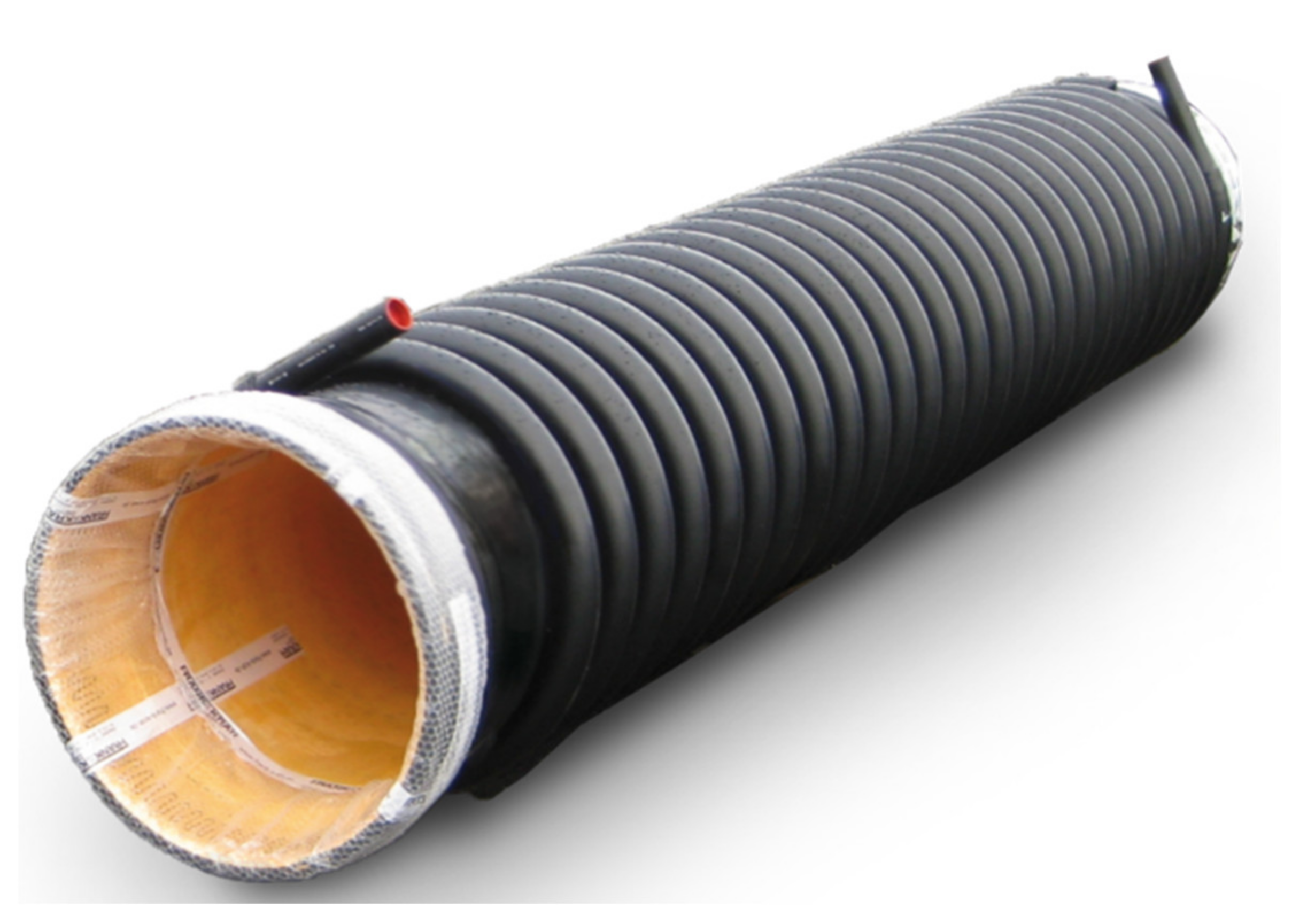
4.2. Hybrid Sewer
The hybrid sewer is a sewer segment made of plastic, which on the one hand fulfills the original task of wastewater transport and on the other hand can extract and supply thermal energy from the wastewater and the surrounding soil. In addition, there are three transport lines above the hybrid duct which can transport thermal energy at different energy levels through the urban quarter, see
Figure 2a.
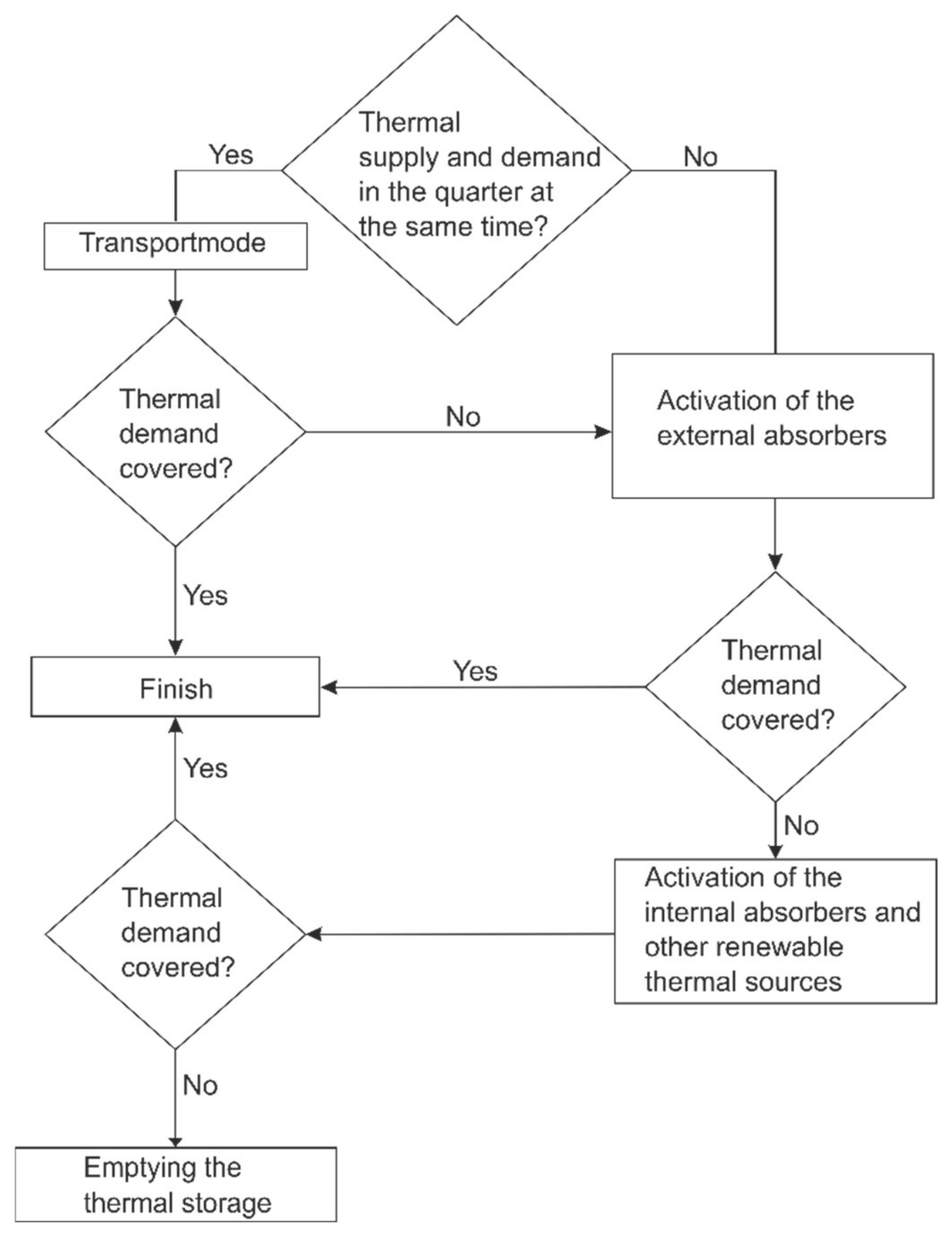
Different thermal needs of the users require different thermal loads on the hybrid sewer. If a user announces a need for thermal energy, a flow chart is started. First, it is checked whether another user in the network wants to supply a surplus of thermal energy. If so, thermal energy is transported, see
Figure 2c. In case there is no user with a thermal surplus in the network, thermal energy is obtained by activating the external absorbers since there is little short-term storage capacity here, see
Figure 2b. External absorbers can also be applied to sewer diameters of up to 300 mm, while inner absorbers (Classic channel absorber) must have a minimum diameter of 800 mm in existing sewers so that they can be walked on by one person in the event of reversal, see
Figure 2a. If the thermal energy generated by activating the external absorbers is not sufficient, the internal absorbers are activated with direct contact to the wastewater, see
Figure 2d. The flow chart of the developed supply concept is presented in
Figure 3.
During building heating, the absorbers are exposed to a cold heat transfer fluid to be heated by the wastewater or the surrounding soil, and vice versa during building cooling. The energy thus obtained is raised to a usable level utilizing a heat pump. In the best case, transported thermal energy does not require an increase of temperature using a heat pump, therefore no additional energetic expenditure by the heat pump is necessary in this case.
For the optimal realization of the sewer cross-sections, the hybrid sewers are varied in their geometrical arrangement and pipe configuration. Small pipe diameters are chosen when a high heat transfer between absorber and environment is needed. A reduction of the cross-section increases the flow velocity and increases the dimensionless heat transfer coefficient. A large diameter, on the other hand, reduces the flow velocity and thus decreases the heat transfer [
38].
The three-dimensional design of the hybrid sewers provides exemplarily for a 6 m long activated plastic sewer section. The absorber pipe is attached to the outer surface of the sewer in the form of a helix, with the consequence that there is a forward flow and a return flow every 6 m.
Figure 4 shows the basic model of the thermally activated hybrid sewer, which both transports wastewater and extracts thermal energy from the surrounding soil, from the air inside the sewer, and from the wastewater via the external absorber pipe.
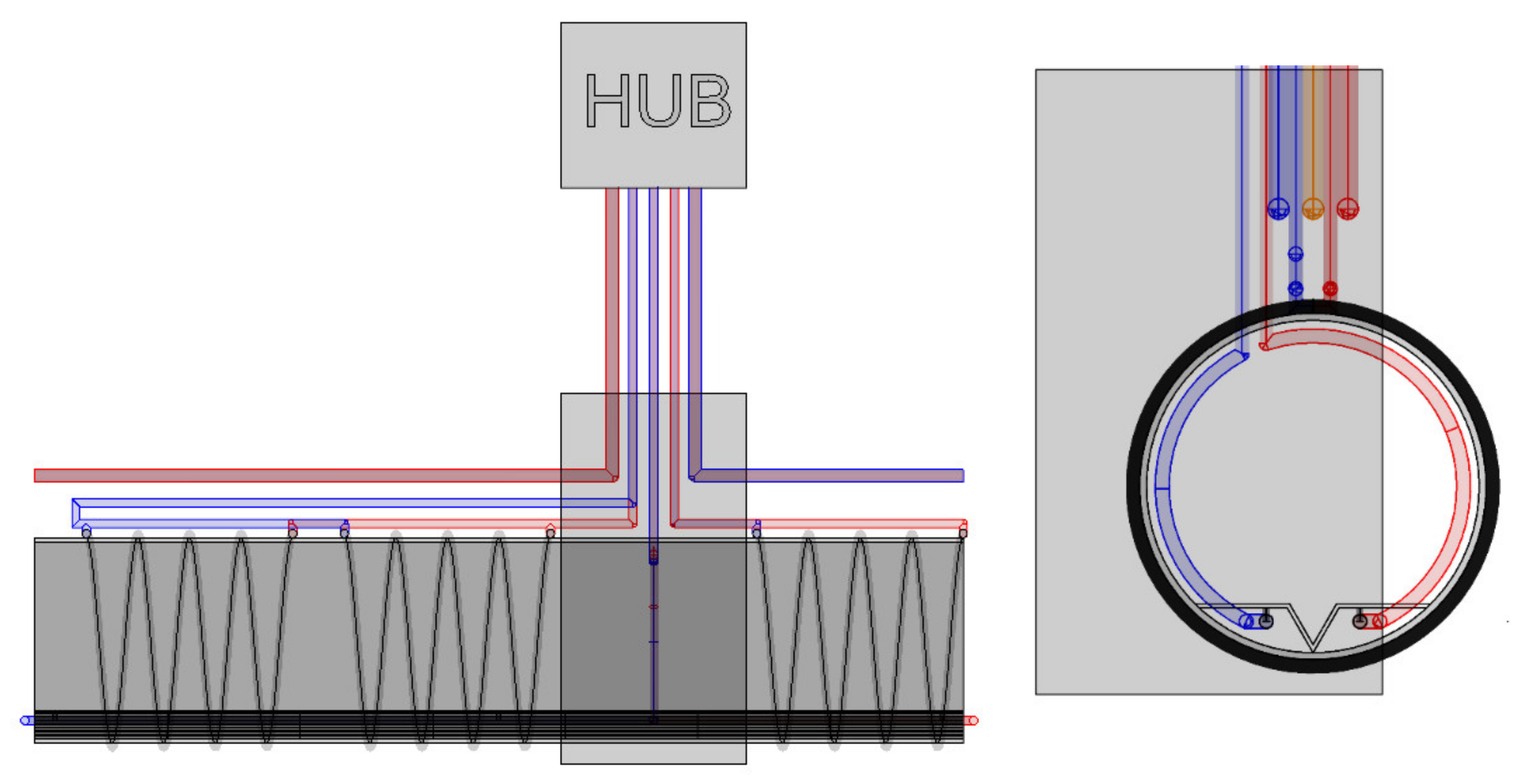
The supply and return lines of the hybrid sewer are connected to the house connection via connecting lines. In the house connection, the thermal energy is processed via a heat exchanger to a heat pump for further use. When connecting the hybrid sewers to the house connection, this can be carried out either in parallel or in series, i.e., either each sewer segment is connected individually to the house connection with a supply and return line each or there is a supply line from which all hybrid sewers are supplied and a return line which collects all return lines. To avoid hydraulic pressure losses and consequently a decrease in performance, the hybrid sewers are laid in series according to the
Tichelmann principle, whereby the sum of the pipe lengths of the supply and return lines is the same for each hybrid sewer. Consequently, the same volume flow passes through each sewer segment, since each sewer segment has the same pressure loss due to pipe friction due to the same pipe lengths, see
Figure 5 and
Figure 6 the house connection is referred to as a hub, for more details see
Section 3.1. The parallel connection was not used in the IWAES project, since with approx. 475 hybrid sewers to be expected, the number of supply and return pipes would be difficult to accommodate in the underground. On the other hand, a positive aspect of using the parallel connection would be that the supply and return lines would also act as a thermal collector.
Access to the internal absorbers is provided by wastewater shafts installed in front of the house connections. In the same figure, the transport pipes (blue, yellow, red) located above can be seen, whose connection to the house connection also runs via the same wastewater shaft.
4.3. Numerical Investigations
The thermal performance of helical absorbers or wastewater absorbers, in general, has not yet been analytically solvable. There are already analytical approaches with which helical geothermal heat absorbers can be calculated analytically, but this is not transferable to wastewater absorbers [
40]. In addition, there is already some research on all heat flows acting in the sewer to predict the temperature of the wastewater depending on time and position in the sewer [
41,
42], heat flows due to the use of absorbers is not considered in detail. Instead of detailed performance calculations, there are schemas for the preliminary evaluation of the performance of wastewater heating, depending on the heat demand, the full load hours, the wastewater discharge, the distance between the extraction point and the demand point, as well as the remaining flow distance [
43]. To determine the thermal performance of the wastewater absorbers, numerical investigations were carried out with the simulation software COMSOL. A completely analytically solved method of calculating the power has not yet been developed, which is why simulations have to be used.
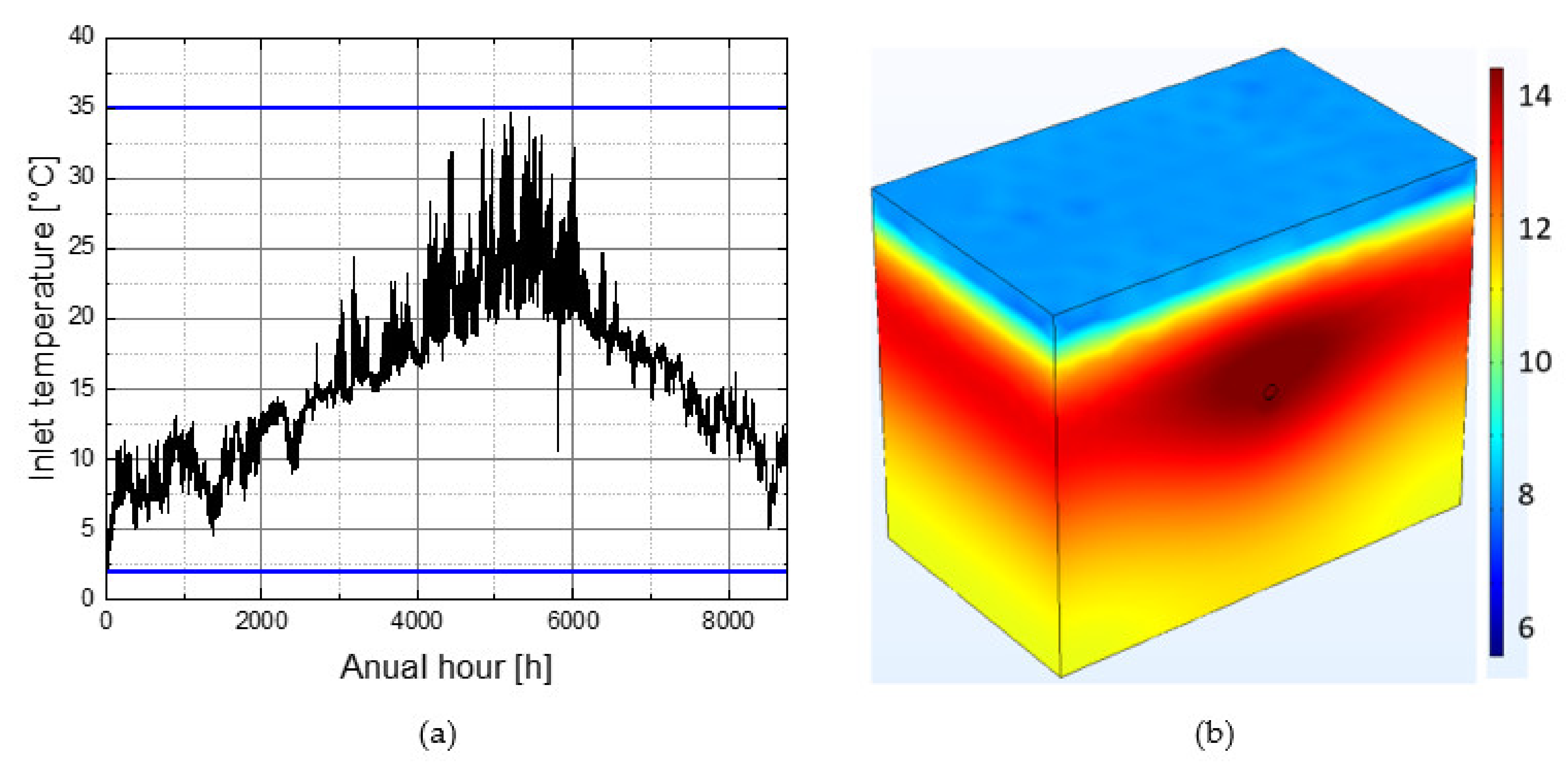
To determine the thermal performance of the hybrid sewers, numerical two-dimensional, as well as three-dimensional calculations, were performed using the simulation software COMSOL, the model used here can be seen in
Figure 7b.
The length of the model is 10 m, 8 m high, and has a depth of 6m. The lower edge and the lateral edges are assumed to be thermally adiabatic, only the upper surface is in contact with the atmosphere. The acting atmospheric influences were mapped using the hourly resolved test reference years of the year 2045 of the German Weather Service [
37]. A Neumann boundary condition was assumed between the atmosphere and the upper edge of the terrain. The formula for determining the heat transfer is given in Formula (2) [
44], the flow conditions were taken from [
37].
represents the heat transfer coefficient and v
the wind speed at the top of the terrain.
The thermal influences from wastewater temperature were formed from hourly temperature measurements at the main sewage treatment plant in Stuttgart-Mühlhausen and was also assumed as convective and so as a Neumann boundary condition in the three-dimensional calculation. From the urban planning design, a project partner drafted the urban water engineering design for the Rosenstein district. The design specifies the diameter, length, and average expected wastewater flow velocity for each sewer section, which were then assumed as flow velocity in the numerical simulation. The flow through the external absorbers was assumed to be slightly turbulent for geothermal systems [
45]. Extra investigations were carried out in IWAES for the sewer air data, the results of which were incorporated into the numerical investigations, see
Section 4.4.
The soil continuum was assumed to be the non-cohesive soil material but saturates typical for the Rosenstein district. The applied load profile was developed within the project for a typical building block. For the load curve, as in the study of the performance of geothermal systems, a coefficient of performance of 3.5 was assumed instead of the in Germany common value of 4.3, thus ensuring a conservative design of the hybrid sewer. The simulation models two years, in the first year only the boundary condition acting on the surface is active, the thermal influence of the wastewater channel is not considered yet. The goal is to obtain a representative temperature regime in the soil. In the second year, the thermal influences of the sewer (sewer air, wastewater) are also active. The thermal load results from the developed hourly resolved load profile and was adjusted according to Equation (1). The required hourly heating load of the load profile is subtracted from the thermal energy of the return flow, then the new flow temperature of the hybrid duct is determined from the remaining power of the absorber fluid. Since the hourly heating requirements vary and the thermal boundary conditions also vary, the flow temperature is also variable. In order not to impair the performance of the treatment plant, the flow temperature must not rise above or fall below a temperature limit. A value of 2 °C was taken as the minimum flow temperature and a value of 35 °C as the maximum flow temperature. According to [
46], the upper limit value results as the maximum inlet temperature to the sewers. The minimum temperature of 2 °C results from the requirement of the protection of medicinal springs not to use glycol as frost protection and the use of tube bundle heat exchangers.
In the numerical calculation, the load profile was divided by the number of hybrid sewers required to handle the load profile. The flow temperature of the hybrid sewer was chosen as the decisive parameter, which must not exceed the 35 °C barrier and must not fall below the 2 °C barrier,
Figure 4a.
The hybrid sewer performance was determined using the following equation and divided by the number of annual full load hours (heating load hours: 1240 h, cooling load hours: 357 h), see
Table 1. In the urban quarter, there are only sewers with diameters of 300 mm, 400 mm, and 800 mm, so only these diameters were investigated. The power of the hybrid channels was calculated using the following formula (1). Where
[l/s] describes the volume flow and
[J/KgK] and
[Kg/L] the heat capacity and density.
[°C] describes the inflow temperature and
the outflow temperature [°C].
According to the wastewater ordinance of the city of Stuttgart, inlets to the wastewater sewer are permitted up to 35 °C. The temperature field of the soil surrounding the sewer is significantly dependent on the heat input of the sewer, which is why an inlet temperature of up to 35 °C can theoretically be assumed, but whether this would be permitted is not finally determined by the legislator. The materials of the developed system would be able to withstand these temperatures; however, it must be considered that using such high temperatures for cooling requires heat pumps and additional electrical energy.
To be on the safe side, a maximum flow temperature of 20 °C is assumed according to [
45], which only applies to purely geothermal systems; wastewater heating is not explicitly mentioned.
Final validation of the numerical model is still pending due to a lack of measurement data and is to be carried out in the continuation and implementation phase of the IWAES project. The numerically determined withdrawal capacities are comparable with measured withdrawal capacities of thermally activated sewers and therefore the determined values can be considered to be plausible. However, the measured extraction values do not consider the wastewater height, wastewater temperature, duct air velocity, etc., which is why these values are not suitable for validation.
4.4. Measurement of the Flow Velocity of the Sewer Air
Investigations in thermally activated tunnels have shown a significant influence of the tunnel air on the possible heat extraction [
47,
48].
Therefore, to determine the thermal performance of hybrid tunnels, it is important to know the temperature and flow of the sewer air. The state of research on sewer air did not include accurate measurements of temperature and flow velocity in relation to wastewater temperature and the studies were not carried out on real sewers with real wastewater but with normal water on above-ground pipes [
49]. Studies on this issue were conducted at the University of Stuttgart in the spring of 2021. For this purpose, different sewer diameters and vessels were equipped with measurement technology and examined, see
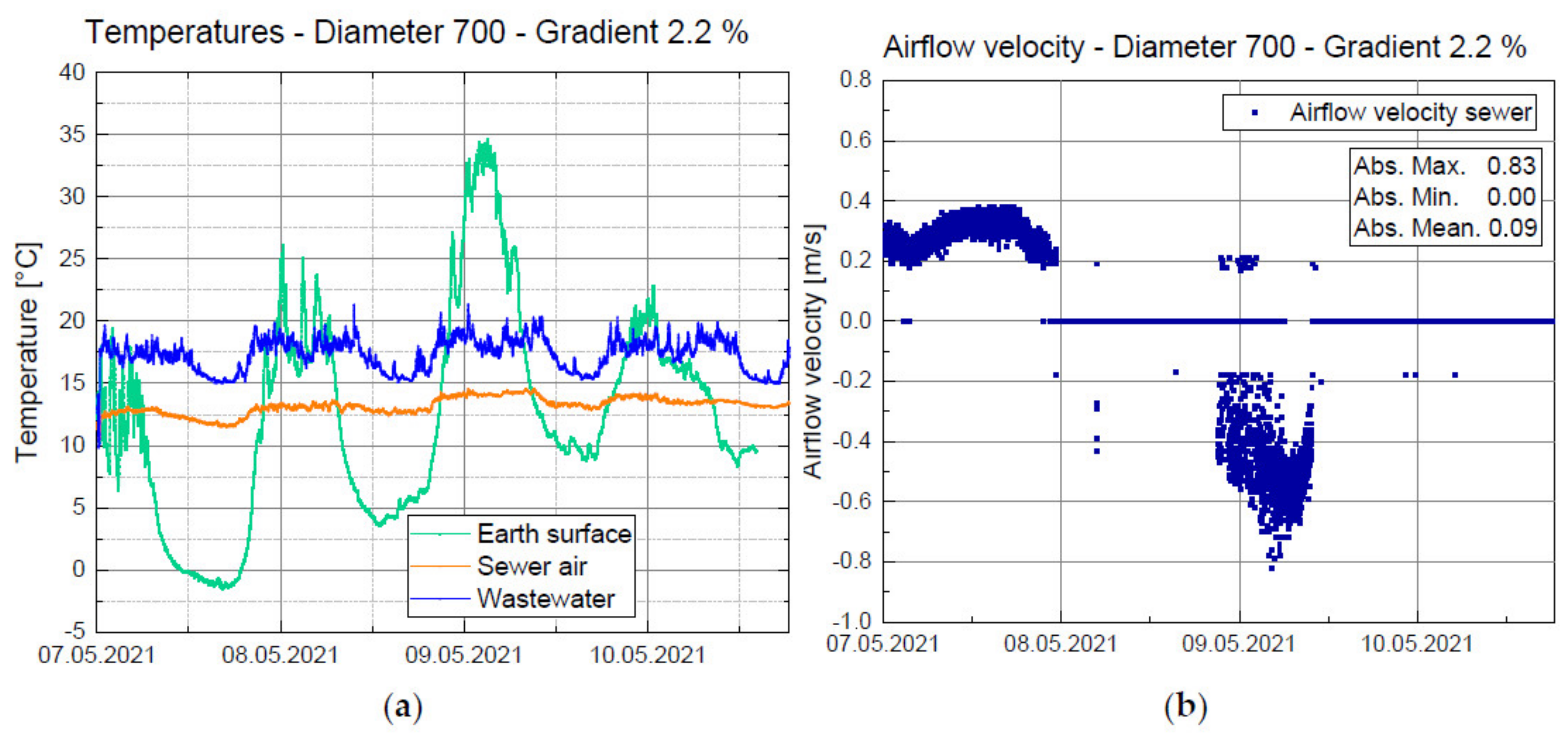
Figure 8. Due to the possible presence of sewer gases in the sewer system, an explosion-proof measuring construction had to be developed, so that instead of a heat wire anemometer for measuring the sewer air velocity, a wind turbine was used, which has a measuring threshold of approx. 0.2 m/s.
Figure 9 a shows the measurement of all relevant temperatures of a sewer (diameter 700 mm). It can be seen that the air temperature in the sewer is constant and only slightly dependent on the surface temperature, but also not exclusively dependent on the wastewater temperature. This correlation can only be explained by the thermal influence of the surrounding soil.
Figure 9b shows that there is airflow in sewers and that it can be independent of the flow direction of the wastewater.
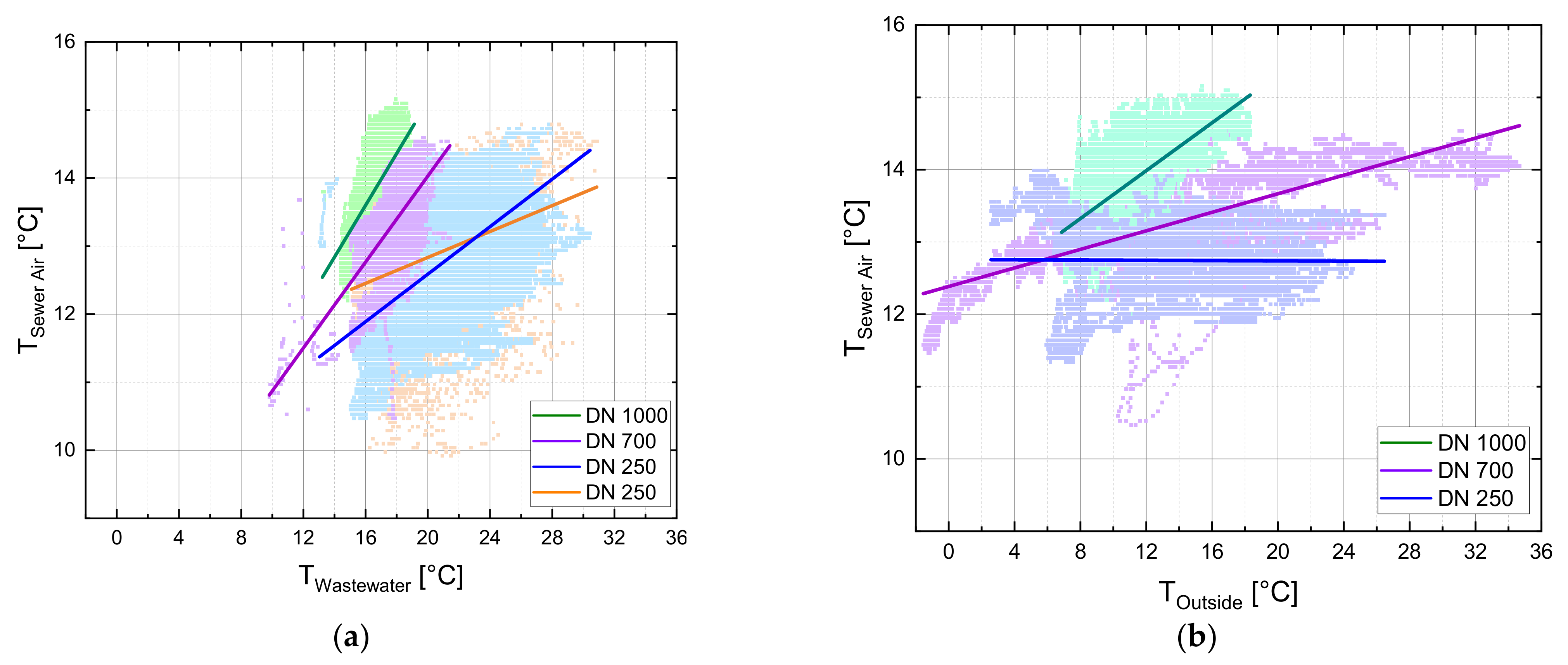
Figure 10a shows that for larger sewer diameters a correlation between sewer air temperature and wastewater temperature exists; the larger the diameter of the sewer, the clearer the correlation between sewer air temperature and wastewater temperature.
Figure 10b indicates also that especially for large sewer diameters there is a correlation between sewer air temperature and outdoor temperature. In summary, it is clear that the larger the sewer diameter, the more likely the sewer air temperature is to interact with the outside temperature; one reason could be the increased flow velocities of the wastewater, which increase the heat transfer between sewer air and outside temperature and sewer air and wastewater. Larger sewer diameters are used for larger discharge values, which usually have higher discharge velocities.
5. Ecological Evaluation of the Concept
The simplified life cycle assessment (LCA) compares the developed system with a reference system, which provides a heat supply through district heating and a cold supply using refrigeration decompression machines. Mainly the emission of GWPs was taken into account, which is why a simplified LCA is discussed here. Not the entire district was considered, but only a representative section. Due to the different and not absolutely determinable uses of the buildings, it is not possible to determine the thermal load profiles of all individual buildings, which is why representative buildings were selected for the simplified LCA. In the life cycle assessment [
50], both the production and the use of the thermal supply systems were examined with regard to their global warming potential. The relevant unit here is the CO
2 equivalent. The IWAES system uses renewable thermal energy sources located in the urban quarter. To process the thermal energy from the absorbents, heat pumps are used which consume electrical energy. The calculation was based on DIN ISO 14040 [
30] and ISO 14044 [
31]. First, the greenhouse gases released during production were determined, i.e., the greenhouse gases released during the production of the individual components (e.g., pipelines, heat exchangers, etc.) were determined and aggregated. The subsequent period of use was assumed to be 50 years, in which case all greenhouse gases released continuously over time (wear and tear of equipment, leakage of oil from pumps, etc.) were added together.
The electrical energy can come either from conventional sources (German electricity mix 2020 (GE): 452 g CO
2 equivalents/kWh) from renewable sources (electricity mixes RE: 71.6 g CO
2 equivalents/kWh) or from photovoltaic (PV: 66.7 g CO
2 equivalents/kWh) and wind (WE: 10.6 g CO
2 equivalents/kWh) [
51]. Most of the district heating produced in Stuttgart (DH: 188 g CO
2 equivalents/kWh) comes from waste incineration and gas-fired power plants [
52]. The IWAES system causes a factor of 5.2 higher CO
2 equivalent emissions in the production phase, during the use phase the CO
2 emissions per kWh are significantly lower so that already after 10 years the IWAES system has a lower CO
2-equivalent emission in total, see
Figure 11 (assuming that the electricity mix maintains the CO
2 equivalent emissions of 2020). If, as is assumed, the composition of the electricity mix changes in the future so that fewer CO
2 equivalents are emitted per kWh, the IWAES system will also emit fewer CO
2 equivalents.
Figure 11, therefore, shows that the break-even point is reached after just less than 5 years when using electrical energy from the electricity mix of renewable sources as well as from wind energy and photovoltaics. The figures assume that the emissions of CO
2 equivalents from district heating remain constant.
6. Study Area Rosenstein District
The Rosenstein district in Stuttgart was chosen as the example study area for the IWAES project approach. The district is located on former track areas that will become redundant due to the new construction of Stuttgart’s main station as an underground station. However, the conversion offers the city an unique opportunity to redesign an inner-city area of 85 hectares, the Rosenstein district. The city announced an urban planning competition in 2019.
The urban design is strongly oriented to the course of the railway tracks and also provides for a large proportion of green and open spaces. According to the design (see
Figure 12), approximately one-third of the Rosenstein district will consist of green and open spaces. The new urban district is to be designed almost car-free. Parking spaces in public areas are not provided. Parking facilities and areas for “new mobility” are to be accommodated in “urban quarter hubs“. The hubs will also serve to accommodate other infrastructure facilities such as daycare centers and other social infrastructure, energy supply facilities, and commerce. Basically, the urban planners aim to implement an “urban, resilient and green” urban district [
53]. Another focus is on the connection of the new urban district to the already existing districts.
The design serves as the basis of the research project, in detail the marked area in
Figure 13. It provides for a dense development, which is characterized by many green areas. The site occupancy ratio (GRZ) is on average 0.56, the Floor Space Index (GFZ) 3.39.
According to the specifications of the city of Stuttgart, the new residential district is to become an energy-plus district. On an annual basis, more energy is to be generated in the district than it consumes. The urban quarter Rosenstein district is characterized by a high degree of compaction and, as a result, increased wastewater runoffs values. The subsoil consists mainly of fill and non-cohesive soils in which groundwater is not to be expected.
The Rosenstein district is a new construction project. Merely the old locomotive workshop in the north of the area is to be preserved. For the IWAES-concept, it is also important to combine the uses in such a way that synergies are created. As far as possible, heat-generating units should be located as close as possible to units that require heat to achieve a fast heat balance and minimize transport losses. In a final step, the remaining demand will be covered by locally generated renewable energy. A major challenge here is that uses can only be defined into the user groups specified by the Land Use Ordinance, such as residential, service and commercial, etc. The uses in an urban district are very dynamic. The changes of use are not comprehensively predictable and are determined by many different influencing factors. Above all, the residential structure determines the demand for specific uses. For heat balancing through waste heat recovery, it would be optimal if all uses were fixed for the long term. However, this is not possible and, in relation to the discipline of urban planning, not desirable. The dynamics in the changes of use make the planning of the heat supply system and the interdisciplinary cooperation very complex. When planning the thermal energy supply network, it is mandatory to integrate it in an energy master plan for urban quarter.
The IWAES project aims to demonstrate a way in which disciplines can converge through interactive processes to achieve a balanced heat budget in mixed-use urban quarters. The results on interdisciplinary collaboration and how this system can best be implemented will be made available in an action guide at the end of the project (September 2022).
7. Discussion
The developed concept is theoretically sound, but the actual application and validation are still pending. The concept has so far only been investigated for the “Rosensteinquartier”, which has a high urban density. This has the advantage that a high volume of wastewater can be expected and the disadvantage that it has a very high energy demand.
Therefore, the applicability of the developed system will be tested in a follow-up project. Here, a district with a different urban density and development will be chosen so that the transferability can be tested and possible barriers can be removed. The simulated models will be validated by measurement results from a real-scale hybrid sewer. For this purpose, this will be equipped with measuring devises. The aim is to create measurement aids from this.
To implement the concept, not only technical but also urban planning issues need to be clarified. How must the administrative structure be changed so that the developed concept can be applied? How can acceptance of the concept be achieved among owners and the population? Who will operate the system and how will the thermal energy be invoiced?
8. Conclusions
This paper demonstrates the relevance of early interdisciplinary collaboration for successful energy master planning. It must consider all the needs of the various disciplines at an early stage in the preparation of urban planning concepts.
This was demonstrated by the example of a concept that allows the use of modified sewers (hybrid sewers) to extract and feed thermal energy from the wastewater and the surrounding soil as well as to transport thermal energy through the urban quarter. By transporting the thermal energy, the different thermal demands are to be balanced as far as possible. To achieve this, representative uses were assumed at corresponding locations in the district. From these uses, thermal load profiles were developed which form the basis of the numerical simulation to determine the average thermal extraction capacities of the hybrid sewers. Thermal-hydraulic parameters which are relevant for the numerical investigation were obtained by specially performed measurements in the sewer. If the energy extracted from the hybrid sewers cannot cover the thermal demand, the concept offers the possibility to integrate further renewable thermal energies as well as storage possibilities. To implement the concept as efficiently as possible, legal and informal planning measures are necessary, which are compiled in an integrated energy master plan specifically for the urban quarter. Although the IWAES system generates a larger GWP during the construction phase, the system draws level with a conventional heat supply system after only 10 years due to the significantly lower primary energy input during the utilization phase. The longer the operating time beyond these 10 years, the greater the advantage of the IWAES system.
In terms of land consumption, the hybrid channel system has the advantage that no surface areas are required. The PV and PVT collectors installed on roofs may conflict with roof terraces or similar. However, there are already concepts for the dual use of roofs as roof gardens and PV. Another idea is to install PV modules on facades.
The material consumption and thus also the emission of greenhouse gases is very low with the energetic use of an infrastructure that is being built anyway.
Author Contributions
Corresponding author, T.K.; Conceptualization, T.K., C.S., S.V.; Methodology, C.S.; D.K.; software, T.K., S.V., M.R., R.K.; Validation, T.K., S.V., M.R.; Formal analysis, S.V., M.R., R.K.; Investigations, T.K., C.S, S.V., M.R.; resources, C.M., D.K., R.K.; Data Curation, T.K., M.R., S.V., R.K.; Writing—original draft, T.K., C.S., S.V., M.R., C.M., D.K., R.K.; Writing—review and editing, T.K., C.S., S.V., M.R., C.M., D.K., R.K.; visualization, T.K., C.S., S.V.; supervision, T.K., C.M.; Project administration, T.K., C.M.; Funding acquisition, C.M., D.K., R.K.; All authors have read and agreed to the published version of the manuscript.
Funding
This research has been founded by the Federal Ministry of Education and Research of the Federal Republic of Germany, grant number 033W106A.
Conflicts of Interest
The authors declare no conflict of interest.
References
- Deutsche Energie-Agentur (dena, 2021): Dena-Gebäudereport 2021–Fokusthemen zum Klimaschutz im Gebäudebereich. 2021. Available online: https://www.dena.de/fileadmin/dena/Publikationen/PDFs/2021/dena-GEBAEUDEREPORT_2021_Fokusthemen_zum_Klimaschutz_im_Gebaeudebereich.pdf (accessed on 1 January 2022).
- Göllinger, T. Energiewende in Deutschland, 1st ed.; Springer: Wiesbaden, Germany, 2021. [Google Scholar]
- Schittenhelm, C.; Kurth, D. Integrierte Betrachtung einer Nachhaltigen Wärme- und Kältebewirtschaftung von Stadtquartieren; Real Corp: Vienna, Austria, 2021; pp. 445–454. [Google Scholar]
- Pless, S.; Polly, B.; Houssainy, S.; Torcellini, P.; Livingood, W.; Zaleski, S.; Jungclaus, M.; Hootman, T.; Craig, M. A Guide to Energy Master Planning of High-Performance Districts and Communities; Technical Report; National Renewable Energy Laboratory: Golden, CO, USA, 2020. Available online: https://www.nrel.gov/docs/fy21osti/78495.pdf (accessed on 1 January 2022).
- Mirakyan, A.; De Guio, R. Integrated energy planning in cities and territories: A review of methods and tools. Renew. Sustain. Energy Rev. 2013, 22, 289–297. [Google Scholar] [CrossRef]
- Haase, M.; Lohse, R. Process of Energy Master planning of resilient communities for comfort and energy solutions in districts. Series: Earth and Environmental Science, 1st Nordic Conference on Zero Emission and Plus Energy Buildings. Trondheim, Nlorway. IOP Conf. Ser. Earth Environ. Sci. 2019, 352, 012019. [Google Scholar] [CrossRef] [Green Version]
- Thery, R.; Zarate, P. Energy planning: A multi-level and multicriteria decision making structure proposal. Cent. Eur. J. Oper. Res. 2009, 17, 265–274. [Google Scholar] [CrossRef] [Green Version]
- Bergmann, T.; Wannke, M. Hochleistungswärmetauscher zur Nutzung von Energie aus Abwasser. BBR Fachmag. Brunn. Leit. 2012, 63, 26–34. [Google Scholar]
- Brandl, H. Energy foundations and other thermo-active ground structures. Géotechnique 2006, 56, 81–122. [Google Scholar] [CrossRef]
- Barla, M.; Insana, A. Energy tunnel segmental lining: And experimental site in Turin metro. In Proceedings of the World Tunnel Congress, Dubai, United Arab Emirates, 21–26 April 2018. [Google Scholar]
- Adam, D.; Markiewicz, R. Energy from earth-coupled structures, foundations, tunnels and sewers. Géotechnique 2009, 59, 229–236. [Google Scholar] [CrossRef]
- Buhmann, P.; Moormann, C.; Westrich, B.; Pralle, N.; Friedemann, W. Tunnel geothermics—A german experience with renewable energy concepts in tunnel projects. Geomech. Energy Environ. 2016, 8, 1–7. [Google Scholar] [CrossRef]
- Bidarmaghz, A.; Narsilio, G.A.; Buhmann, P.; Moormann, C.; Westrich, B. Numerical and experimental investigation of geothermal integration into tunnels. In Proceedings of the 19th International Conference on Soil Mechanics and Geotechnical Engineering, Seoul, Korea, 17–21 September 2017; Korea Geotechnical Society: Seoul, Korea, 2017. [Google Scholar]
- Moormann, C.; Buhmann, P.; Friedemann, W.; Homuth, S.; Pralle, N. Tunnel geothermics—International experience with renewable energy concepts in tunneling. Geomech. Tunn. 2016, 9, 467–480. [Google Scholar] [CrossRef]
- Kürten, S. Zur Thermischen Nutzung des Untergrunds mit Flächigen Thermo-Aktiven Bauteilen. Ph.D. Thesis, RWTH Aachen University, Aachen, Germany, 2016. [Google Scholar]
- Amatya, B.L.; Soga, K.; Bourne-Webb, P.J.; Amis, T.; Laloui, L. Thermo-mechanical behavior of energy piles. Géotechnique 2012, 62, 503–519. [Google Scholar] [CrossRef]
- Laloui, L.; Rotta Loria, A.F. Analysis and Design of Energy Geostructures, 1st ed.; Elsevier: London, UK, 2019. [Google Scholar]
- Cipolla, S.; Maglionico, M. Heat recovery from urban wastewater: Analysis of the variability of flow rate and temperature in the sewer of Bologna. In Proceedings of the 68th Conference of the Italian Thermal Machines Engineering Association, Bologna, Italy, 11–13 September 2013. [Google Scholar]
- Erhorn, H.; Görres, J.; Illner, M.; Bruhn, J.-P.; Bergmann, A. “NeckarPark Stuttgart”: District heat from wastewater. In Proceedings of the 16th International Symposium on District Heating and Cooling, Hamburg, Germany, 9–12 September 2018. [Google Scholar]
- Frijns, J.; Hofmann, J.; Nederlof, M. The potential of (waste)water as energy carrier. Energy Convers. Manag. 2012, 65, 357–363. [Google Scholar] [CrossRef]
- Schmid, F. Sewage Water: Interesting Heat Source for Heat Pumps and Chillers; Swiss Energy Agency for Infrastructure Plants: Zurich, Switzerland, 2009. [Google Scholar]
- Lund, H.; Werner, S.; Wiltshire, R.; Svendsen, S.; Thorsen, J.E.; Hvelplund, F.; Mathiesen, B.V. 4th Generation District Heating (4GDH) Integrating smart thermal grids into future sustainable energy systems. Energy 2014, 68, 1–11. [Google Scholar] [CrossRef]
- Romanov, D.; Pelda, J.; Holler, J. Technical, economic and ecological effects of lowering temperatures in the Moscow district heating system. Energy 2020, 211, 118680. [Google Scholar] [CrossRef]
- Pellegrini, M.; Bianchini, A. The innovative concept of Cold District Heating Networks: A literature review. Energies 2018, 11, 236. [Google Scholar] [CrossRef] [Green Version]
- Tol, H.; Svendsen, S. The exergetic, environmental and economic effect of the hydrostatic design static pressure level on the pipe dimensions of low-energy district heating networks. Challanges 2013, 4, 1–16. [Google Scholar] [CrossRef] [Green Version]
- Bünning, F.; Wetter, M.; Fuchs, M.; Muller, D. Bidirectional low temperature district energy systems with agent-based control: Performance comparison and operation optimization. Appl. Energy 2017, 209, 502–515. [Google Scholar] [CrossRef] [Green Version]
- Buffa, S.; Cozzini, M.; D’Antoni, M.; Baratieri, M.; Fedrizzi, R. 5th generation district heating and cooling systems: A review of existing cases in Europe. Renew. Sustain. Energy Rev. 2019, 104, 504–522. [Google Scholar] [CrossRef]
- Boesten, S.; Ivens, W.; Dekker, S.C.; Eijdems, H. 5th generation district heating and cooling systems as a solution for renewable urban thermal energy supply. Adv. Geosci. 2019, 49, 129–136. [Google Scholar] [CrossRef] [Green Version]
- Laajalehto, T.; Kuosa, M.; Mäkilä, T.; Lampinen, M.; Lahdelma, R. Energy efficiency improvements utilizing mass flow control and a ring topology in a district heating network. Appl. Therm. Eng. 2014, 69, 86–95. [Google Scholar] [CrossRef]
- EN ISO 14040: 2021—02; Environmental Management—Life Cycle Assessment—Principles and Framework. German Version; Beuth: Berlin, Germany, 2021.
- EN ISO 14044: 2018—05; Environmental Management—Life Cycle Assessment—Requirements and Guidelines. German Version; Beuth: Berlin, Germany, 2018.
- Guileen-Lambea, S.; Carvalho, M.; Delgado, M.; Lazaro, A. Sustainable enhancement of district heating and cooling configurations by combining thermal energy storage and life cycle assessment. Clean Technol. Environ. Policy 2021, 23, 857–867. [Google Scholar] [CrossRef]
- Moreno, P.; Castell, A.; Sole, C.; Zsembinszki, G.; Cabeza, L. PCM thermal energy storage tanks in heat pump system for space cooling. Energy Build. 2014, 82, 399–405. [Google Scholar] [CrossRef]
- Waqas, A.; Ud Din, Z. Phase change material (PCM) storage for free cooling of buildings—A review. Renew. Sustain. Energy Rev. 2013, 18, 607–625. [Google Scholar] [CrossRef]
- Maucher, A. Erzeugung von Wärme- und Kältelastprofilen anhand von Simulationsparametern der SIA2024 zur Abschätzung des Energie- und Leistungsbedarfes in der frühen Planungsphase; Research Project; Biberach University of Applied Sciences: Biberach, Germany, 2020. [Google Scholar]
- SIA—Swiss society of Engineers and Architects. SIA 2024—Raumnutzungsdaten für Energie-und Gebäudetechnik; Norm: Zürich, Switzerland, 2015. [Google Scholar]
- TRY. Deutscher Wetterdienst. Ortsgenaue Testreferenzjahre von Deutschland für Mittlere, Extreme und Zukünftige Wetterverhältnisse; Handbuch: Offenbach, Germany, 2017. [Google Scholar]
- Von Böckh, P.; Wetzel, T. Heat Transfer, 1st ed.; Springer: Berlin/Heidelberg, Germany, 2012. [Google Scholar]
- Jekel, S.; Seitz, M. Available online: https://www.frank-gmbh.de/de-wAssets/docs/download-englisch/abwasser/PKS-Thermpipe_Prospekt_engl_mail.pdf (accessed on 1 January 2022).
- Li, M.; Lai, A. Heat-source solutions to heat conduction in anisotropic media with application to pile and borehole ground heat exchangers. Appl. Energy 2012, 96, 451–458. [Google Scholar] [CrossRef]
- Dürrenmatt, D.; Wanner, O. A mathematical model to predict the effect of heat recovery on the wastewater temperature in sewers. Water Res. 2014, 48, 548–558. [Google Scholar] [CrossRef] [PubMed]
- Figueroa, A.; Hadengue, B.; Leitao, J.; Rieckermann, J.; Blumensaat, F. A distributed heat transfer model for thermal-hydraulic analyses in sewer networks. Water Res. 2021, 204, 117649. [Google Scholar] [CrossRef] [PubMed]
- Huber, F.; Neugebauer, G.; Ertl, T.; Kretschmer, F. Suitability Pre-Assessment of in-Sewer Heat Recovery Sites Combining Energy and Wastewater Perspectives. Energies 2020, 13, 6680. [Google Scholar] [CrossRef]
- Beisel, S. Vermessung, Moellierung und Bewertung des Erdreichwärmeübertragers beim Passiv-Solarhaus Cölbe. Ph.D. Thesis, University of Marburg, Marburg, Germany, 1999. [Google Scholar]
- VDI-4640-Part 2; Thermal Use of the Underground—Ground Source Heat Pump Systems. Beuth: Berlin, Germany, 2019.
- Statutes of the State capital Stuttgart on Public Wastewater Disposal (Wastewater Disposal Statutes—AbwS); Amtsblatt der Landeshauptstadt Stuttgart: Stuttgart, Germany, 2019.
- Buhmann, P. Energetisches Potential geschlossener Tunnelgeothermiesysteme. In Mitteilungen des Institutes für Geotechnik der Universität Stuttgart; University of Stuttgart: Stuttgart, Germany, 2019; Volume 73. [Google Scholar]
- Schneider, M. Zur energetischen Nutzung von Tunnelbauwerken—Messungen und Numerische Berechnungen am Beispiel Fasanenhof; Mitteilungen des Institutes für Geotechnik der Universität Stuttgart, University of Stuttgart: Stuttgart, Germany, 2013; Volume 68. [Google Scholar]
- Edwini-Bonsu, S. Air flow in sanitary sewer conduits due to wastewater drag: A computational fluid dynamics approach. J. Environ. Eng. Sci. 2004, 3, 331–342. [Google Scholar] [CrossRef]
- Beck, R.; Held, M. Life Cycle Assessment of a Heat Supply System for City Districts. Bachelor’s Thesis, University of Stuttgart, Stuttgart, Germany, 15 January 2022. [Google Scholar]
- Icha, P.; Lauf, T.; Kuhs, G. Entwicklung der Spezifischen Kohlendioxid-Emissionen des Deutschen Strommix in den Jahren 1990–2020; Climate Change: Dessau, Germany, 2021. [Google Scholar]
- Available online: https://www.enbw.com/fernwaerme/geschaeftskunden (accessed on 15 December 2021).
- Arat, C.; Weinmann, M.; Köber, J. Rosenstein—Ideen für den Neuen Stadtteil, Städtebaulicher Wettbewerb der Landeshauptstadt Stuttgart, Asp; Architekten GmbH/ Koeber Landschaftsarchitektur GmbH: Stuttgart, Germany, 2018. [Google Scholar]
Figure 1.
Three-stage thermal district approach with integration of the thermally activated wastewater network, starting from the left: block, hub area, district.
Figure 1.
Three-stage thermal district approach with integration of the thermally activated wastewater network, starting from the left: block, hub area, district.
Figure 2.
Several operating modes: (a) Definition of the absorbers; (b) Input in the ground; (c) Transport of thermal energy; (d) Extraction of thermal energy from wastewater.
Figure 2.
Several operating modes: (a) Definition of the absorbers; (b) Input in the ground; (c) Transport of thermal energy; (d) Extraction of thermal energy from wastewater.
Figure 3.
Flowchart of the activation process.
Figure 3.
Flowchart of the activation process.
Figure 4.
Thermally activated sewer. Reprinted with permission from [
39].
Figure 4.
Thermally activated sewer. Reprinted with permission from [
39].
Figure 5.
Tichelmann connection of the hybrid sewers. On the left, you can see the external absorbers together with the connecting lines and on the right, in section, the internal absorbers of the system, also together with the connecting lines.
Figure 5.
Tichelmann connection of the hybrid sewers. On the left, you can see the external absorbers together with the connecting lines and on the right, in section, the internal absorbers of the system, also together with the connecting lines.
Figure 6.
Perspective of the hybrid sewer.
Figure 6.
Perspective of the hybrid sewer.
Figure 7.
(a) Numerical determined inlet temperature, the bars on height 35 °C and 2 °C represent the limit values which may not be exceeded and fallen below. (b) Three-dimensional numerical model of the hybrid sewer (legend: temperature in °C), the diameter of the sewer is 30 cm.
Figure 7.
(a) Numerical determined inlet temperature, the bars on height 35 °C and 2 °C represent the limit values which may not be exceeded and fallen below. (b) Three-dimensional numerical model of the hybrid sewer (legend: temperature in °C), the diameter of the sewer is 30 cm.
Figure 8.
Schematic representation of the measurement concept.
Figure 8.
Schematic representation of the measurement concept.
Figure 9.
(a) Measurement of the temperatures relevant to the sewer as well as the measured airflow velocity in the sewer (b). In the range below and above 0.2 m/s, the following could not be detected.
Figure 9.
(a) Measurement of the temperatures relevant to the sewer as well as the measured airflow velocity in the sewer (b). In the range below and above 0.2 m/s, the following could not be detected.
Figure 10.
(a) Sewage canal air temperature as a function of sewage temperature. (b) sewage canal air temperature as a function of the ambient temperature (DN: Inner Diameter of the sewer [mm]).
Figure 10.
(a) Sewage canal air temperature as a function of sewage temperature. (b) sewage canal air temperature as a function of the ambient temperature (DN: Inner Diameter of the sewer [mm]).
Figure 11.
Global warming potential (GWP) of the IWAES system in comparison of the Global warning potential of the reference district (RQ) by several electric energy supplies (GE: German electricity mix 2020, RE: German renewable electricity mix 2020, PV: Electricity energy only generated by photovoltaic, Wind: Electricity only generated by wind).
Figure 12.
Winning design of the urban planning competition for the Rosenstein district in Stuttgart. Reprinted with permission from ref. [
53].
Figure 12.
Winning design of the urban planning competition for the Rosenstein district in Stuttgart. Reprinted with permission from ref. [
53].
Figure 13.
Density model of the Rosenstein district.
Figure 13.
Density model of the Rosenstein district.
Table 1.
Heat extraction at 1240 operating hours and heat input at 357 operating hours.
Table 1.
Heat extraction at 1240 operating hours and heat input at 357 operating hours.
| Heating | Cooling |
|---|
| Max. inlet temperature | 35 °C | 20 °C | Min. inlet temperature | 2 °C |
| Sewer diameter | Inner surface | Sewer diameter | Inner surface |
| [mm] | [W/m2] | [W/m2] | [mm] | [W/m2] |
| 300 | 830 | 280 | 300 | 143 |
| 400 | 709 | 250 | 400 | 129 |
| 800 | 641 | 191 | 800 | 117 |
| Publisher’s Note: MDPI stays neutral with regard to jurisdictional claims in published maps and institutional affiliations. |
© 2022 by the authors. Licensee MDPI, Basel, Switzerland. This article is an open access article distributed under the terms and conditions of the Creative Commons Attribution (CC BY) license (https://creativecommons.org/licenses/by/4.0/).


 ,
, 


