A Lipid-Bilayer-On-A-Cup Device for Pumpless Sample Exchange

 , , , and
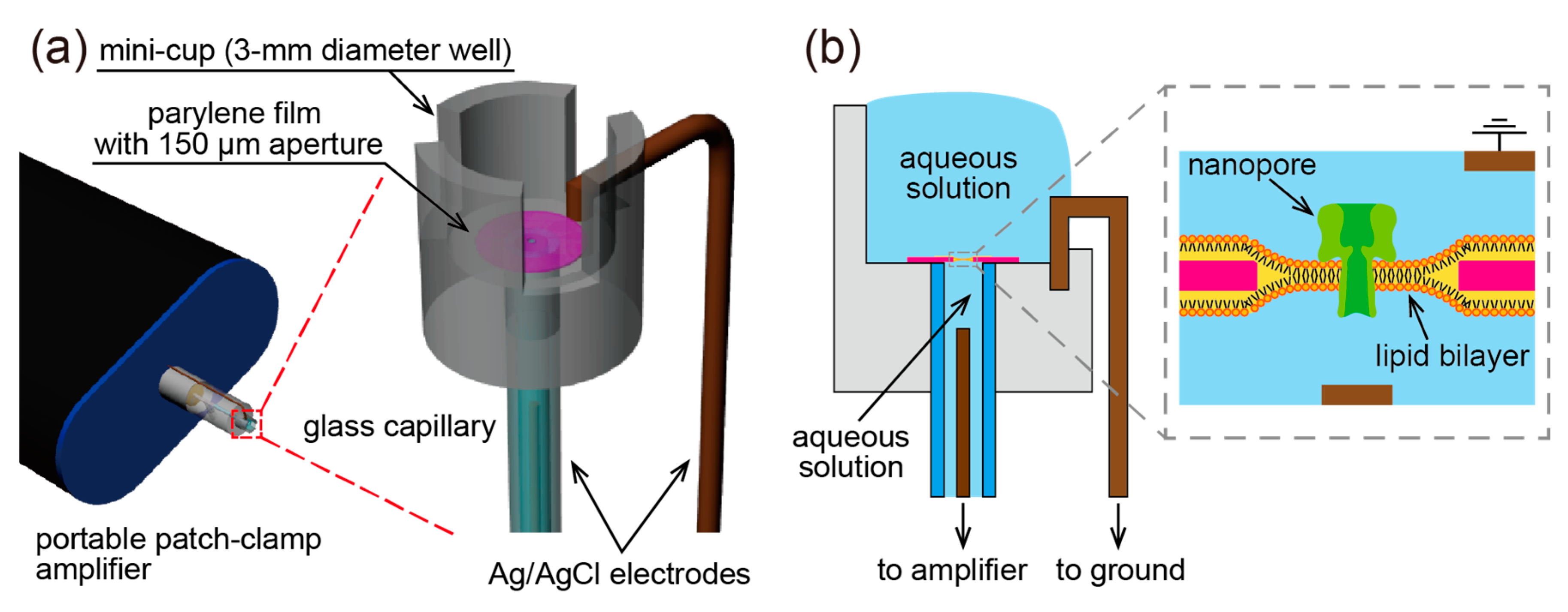
Abstract
:1. Introduction
2. Materials and Methods
2.1. Materials
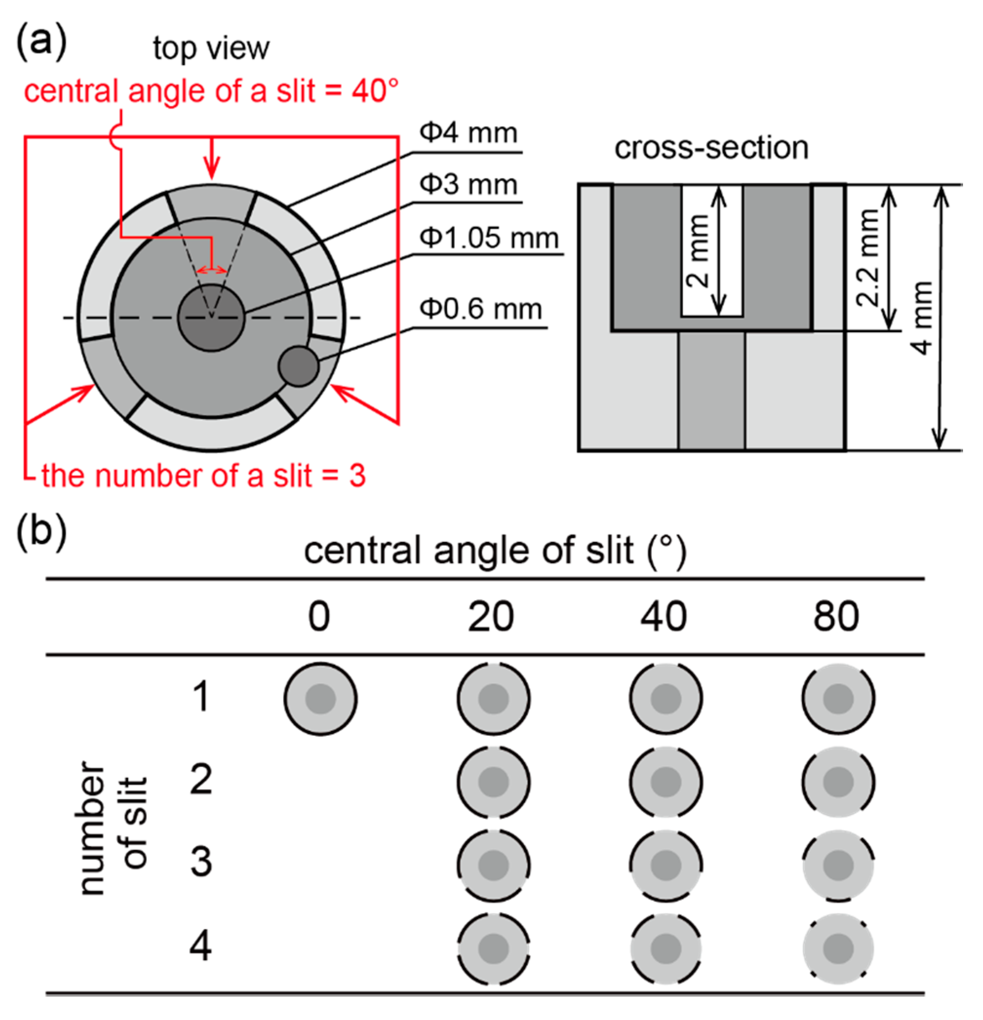
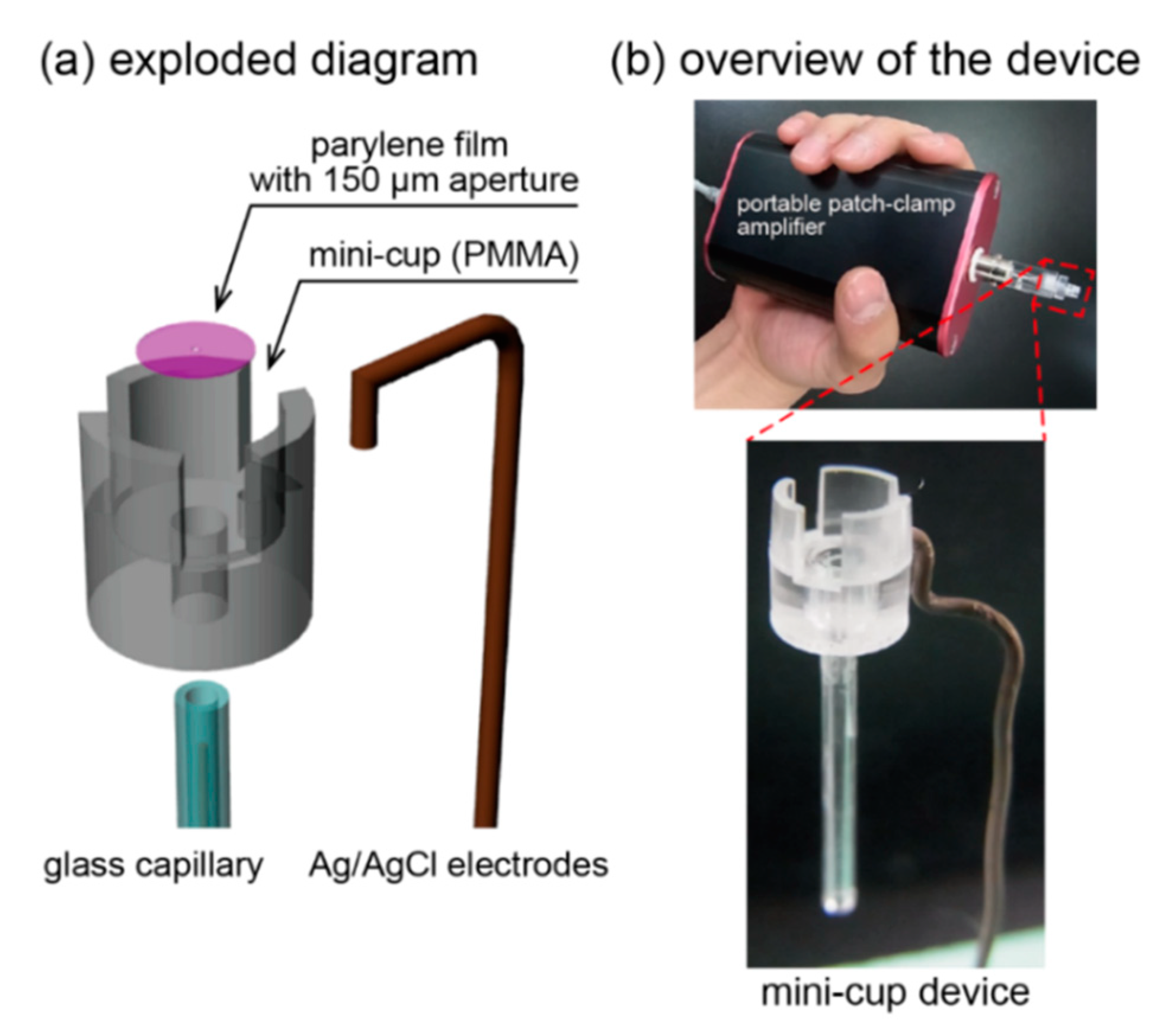
2.2. Mini-Cup Design
2.3. Device Fabricatioin
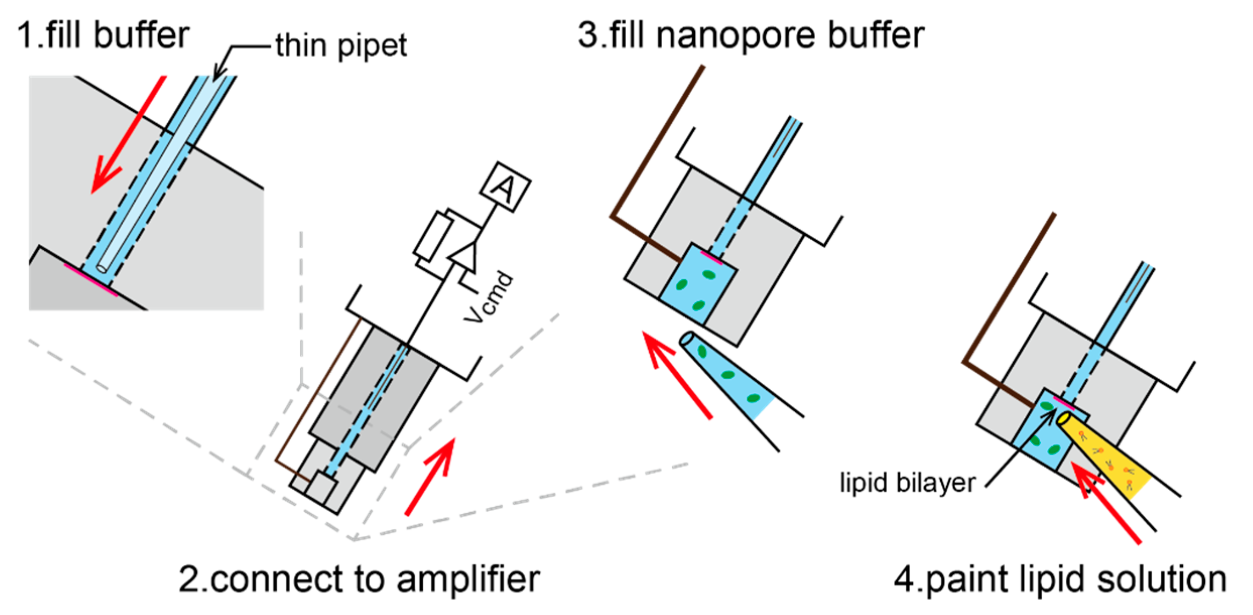
2.4. Lipid-Bilayer Formation and Nanopore Reconstitution
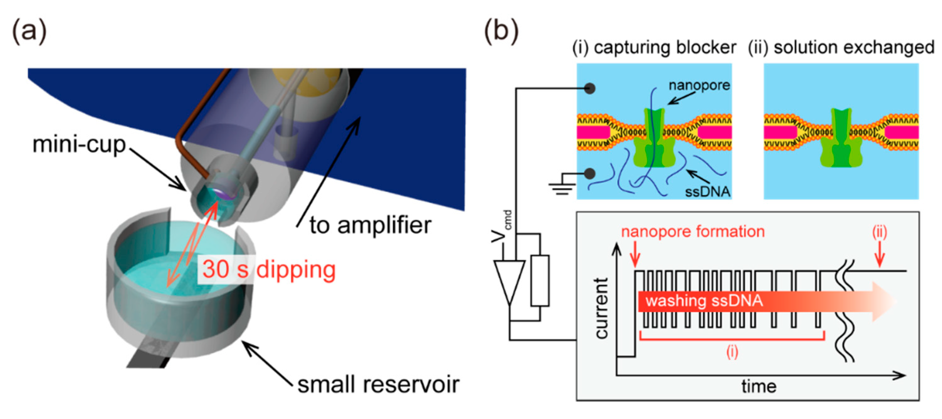
2.5. Ionic Current Recording with Solution Exchange
3. Results and Discussion
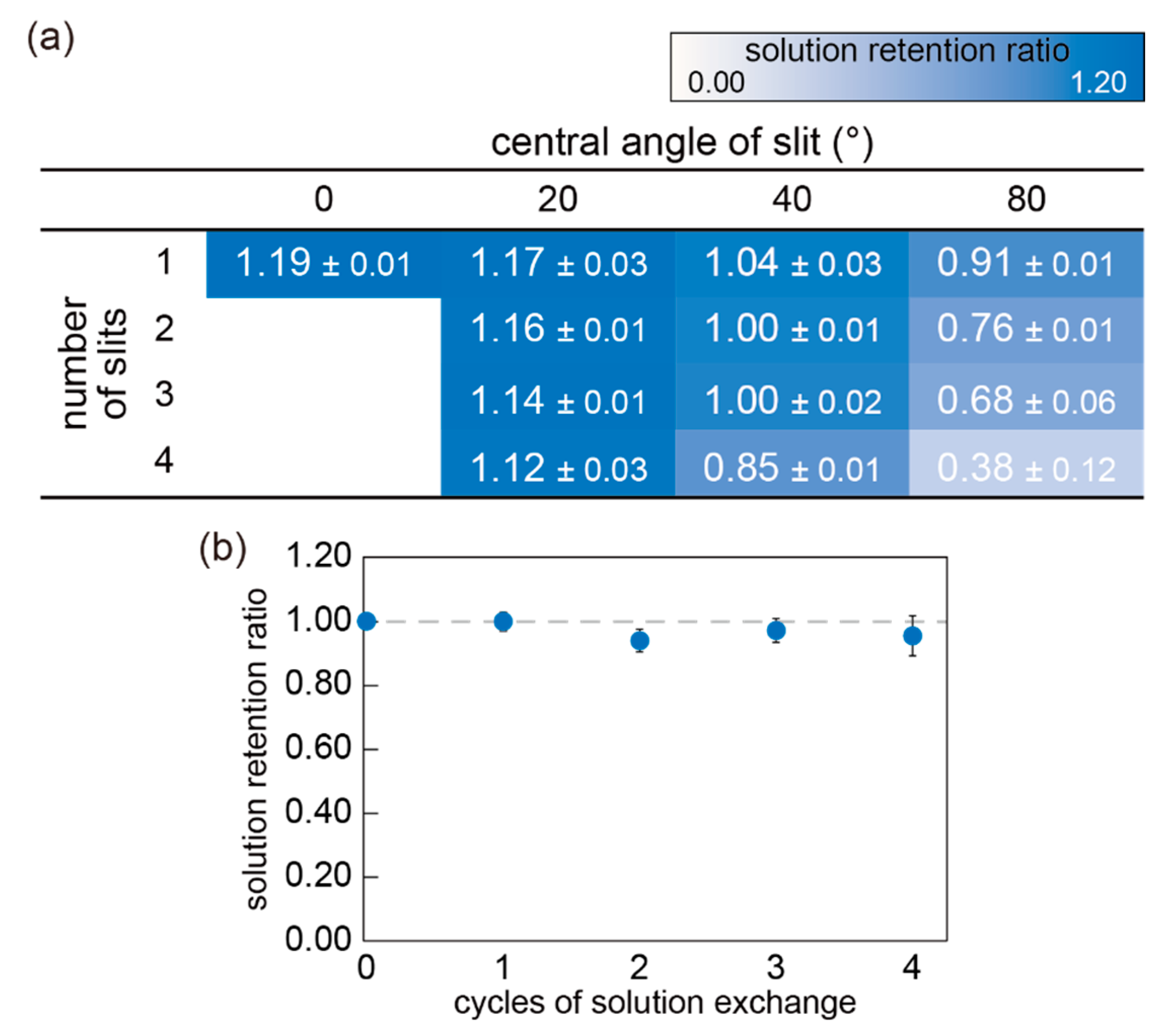
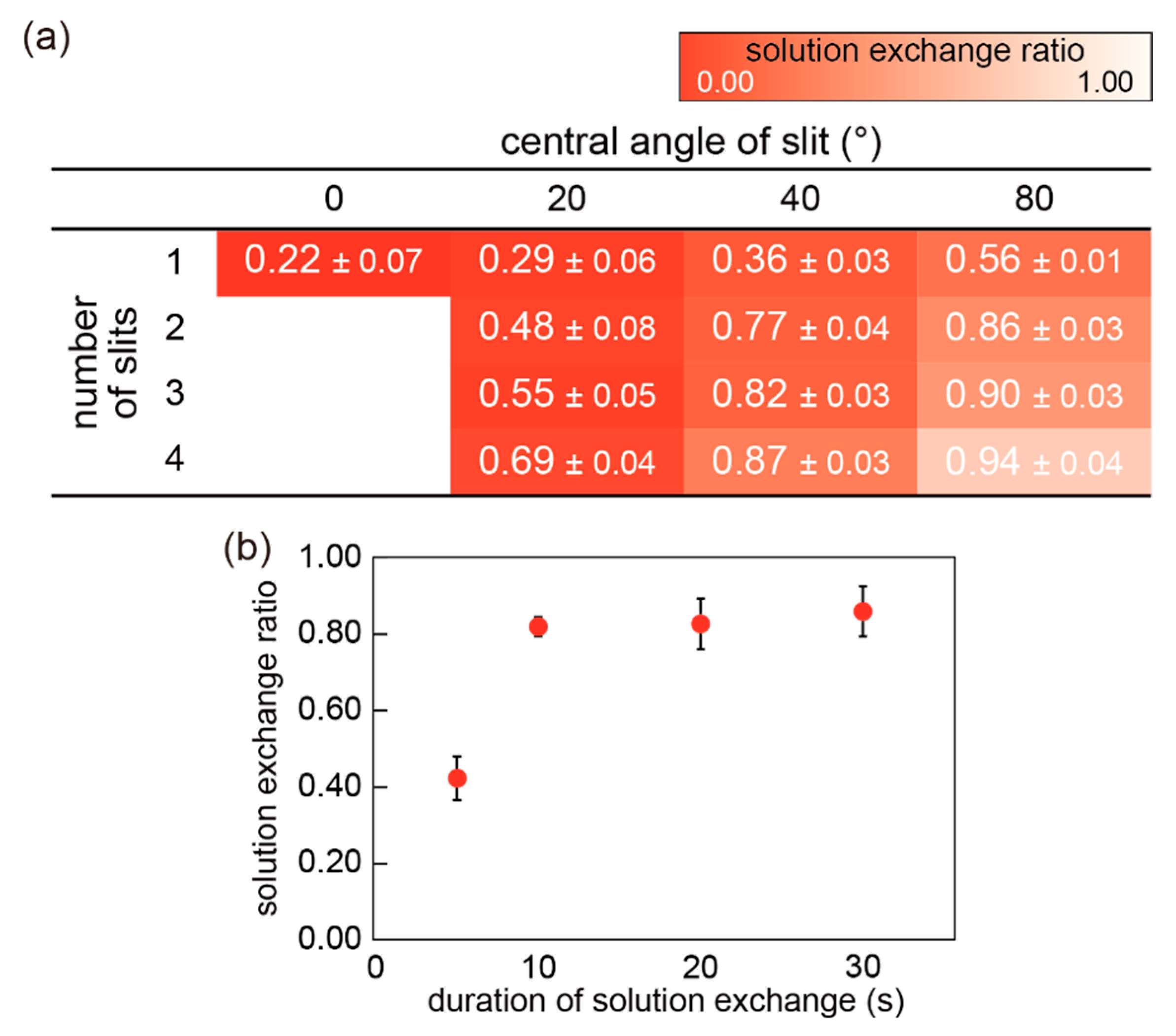
3.1. Optimization of Mini-Cup Design
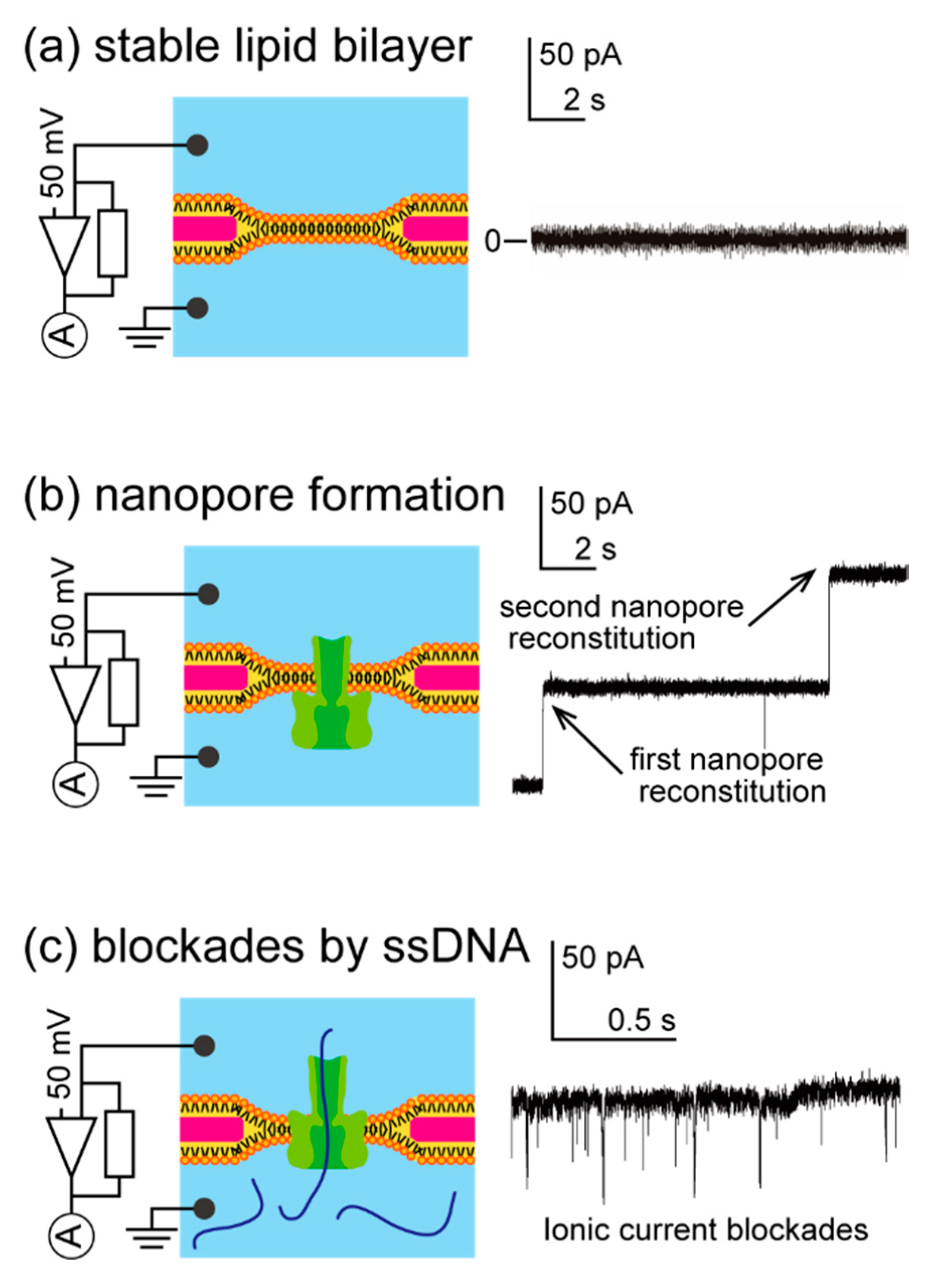
3.2. Nanopore Formation Using the Mini-Cup Device
3.3. Demonstration of Solution Exchange with Mini-Cup Device
4. Conclusions
Supplementary Materials
Author Contributions
Funding
Acknowledgments
Conflicts of Interest
References
- Osaki, T.; Takeuchi, S. Artificial Cell Membrane Systems for Biosensing Applications. Anal. Chem. 2017, 89, 216–231. [Google Scholar] [CrossRef] [PubMed]
- Misawa, N.; Osaki, T.; Takeuchi, S. Membrane protein-based biosensors. J. R. Soc. Interface 2018, 15, 20170952. [Google Scholar] [CrossRef]
- Wang, G.; Wang, L.; Han, Y.; Zhou, S.; Guan, X. Nanopore Stochastic Detection: Diversity, Sensitivity, and Beyond. Acc. Chem. Res. 2013, 46, 2867–2877. [Google Scholar] [CrossRef] [PubMed]
- Zhao, Q.; de Zoysa, R.S.S.; Wang, D.; Jayawardhana, D.A.; Guan, X. Real-Time Monitoring of Peptide Cleavage Using a Nanopore Probe. J. Am. Chem. Soc. 2009, 131, 6324–6325. [Google Scholar] [CrossRef] [PubMed]
- Wang, H.-Y.; Ying, Y.-L.; Li, Y.; Kraatz, H.-B.; Long, Y.-T. Nanopore Analysis of β-Amyloid Peptide Aggregation Transition Induced by Small Molecules. Anal. Chem. 2011, 83, 1746–1752. [Google Scholar] [CrossRef]
- Zhang, X.; Wang, Y.; Fricke, B.L.; Gu, L.-Q. Programming Nanopore Ion Flow for Encoded Multiplex MicroRNA Detection. ACS Nano 2014, 8, 3444–3450. [Google Scholar] [CrossRef]
- Wang, Y.; Zheng, D.; Tan, Q.; Wang, M.X.; Gu, L.-Q. Nanopore-based detection of circulating microRNAs in lung cancer patients. Nat. Nanotechnol. 2011, 6, 668–674. [Google Scholar] [CrossRef]
- Fujii, S.; Kamiya, K.; Osaki, T.; Misawa, N.; Hayakawa, M.; Takeuchi, S. Purification-Free MicroRNA Detection by Using Magnetically Immobilized Nanopores on Liposome Membrane. Anal. Chem. 2018, 90, 10217–10222. [Google Scholar] [CrossRef]
- Fujii, S.; Nobukawa, A.; Osaki, T.; Morimoto, Y.; Kamiya, K.; Misawa, N.; Takeuchi, S. Pesticide vapor sensing using an aptamer, nanopore, and agarose gel on a chip. Lab Chip 2017, 17, 2421–2425. [Google Scholar] [CrossRef]
- Wang, Y.; Montana, V.; Grubišić, V.; Stout, R.F.; Parpura, V.; Gu, L.-Q. Nanopore sensing of botulinum toxin type B by discriminating an enzymatically cleaved Peptide from a synaptic protein synaptobrevin 2 derivative. ACS Appl. Mater. Interfaces 2015, 7, 184–192. [Google Scholar] [CrossRef] [Green Version]
- Kawano, R.; Osaki, T.; Sasaki, H.; Takinoue, M.; Yoshizawa, S.; Takeuchi, S. Rapid Detection of a Cocaine-Binding Aptamer Using Biological Nanopores on a Chip. J. Am. Chem. Soc. 2011, 133, 8474–8477. [Google Scholar] [CrossRef] [PubMed]
- Wu, H.-C.; Bayley, H. Single-molecule detection of nitrogen mustards by covalent reaction within a protein nanopore. J. Am. Chem. Soc. 2008, 130, 6813–6819. [Google Scholar] [CrossRef]
- Guan, X.; Gu, L.-Q.; Cheley, S.; Braha, O.; Bayley, H. Stochastic Sensing of TNT with a Genetically Engineered Pore. ChemBioChem 2005, 6, 1875–1881. [Google Scholar] [CrossRef]
- Wang, L.; Han, Y.; Zhou, S.; Wang, G.; Guan, X. Nanopore Biosensor for Label-Free and Real-Time Detection of Anthrax Lethal Factor. ACS Appl. Mater. Interfaces 2014, 6, 7334–7339. [Google Scholar] [CrossRef] [PubMed]
- Jeon, T.-J.; Poulos, J.L.; Schmidt, J.J. Long-term storable and shippable lipid bilayer membrane platform. Lab Chip 2008, 8, 1742–1744. [Google Scholar] [CrossRef] [PubMed]
- Shim, J.W.; Gu, L.Q. Stochastic Sensing on a Modular Chip Containing a Single-Ion Channel. Anal. Chem. 2007, 79, 2207–2213. [Google Scholar] [CrossRef] [Green Version]
- Venkatesan, G.A.; Sarles, S.A. Droplet immobilization within a polymeric organogel improves lipid bilayer durability and portability. Lab Chip 2016, 16, 2116–2125. [Google Scholar] [CrossRef]
- Jung, S.-H.; Choi, S.; Kim, Y.-R.; Jeon, T.-J. Storable droplet interface lipid bilayers for cell-free ion channel studies. Bioprocess Biosyst. Eng. 2012, 35, 241–246. [Google Scholar] [CrossRef]
- Kang, X.; Cheley, S.; Rice-Ficht, A.C.; Bayley, H. A Storable Encapsulated Bilayer Chip Containing a Single Protein Nanopore. J. Am. Chem. Soc. 2007, 129, 4701–4705. [Google Scholar] [CrossRef]
- Kawano, R.; Tsuji, Y.; Kamiya, K.; Kodama, T.; Osaki, T. A Portable Lipid Bilayer System for Environmental Sensing with a Transmembrane Protein. PLoS ONE 2014, 9, 102427. [Google Scholar] [CrossRef]
- Kawano, R.; Osaki, T.; Sasaki, H.; Takeuchi, S. A Polymer-Based Nanopore-Integrated Microfluidic Device for Generating Stable Bilayer Lipid Membranes. Small 2010, 6, 2100–2104. [Google Scholar] [CrossRef] [PubMed]
- Oshima, A.; Hirano-Iwata, A.; Mozumi, H.; Ishinari, Y.; Kimura, Y.; Niwano, M. Reconstitution of Human Ether-a-go-go -Related Gene Channels in Microfabricated Silicon Chips. Anal. Chem. 2013, 85, 4363–4369. [Google Scholar] [CrossRef] [PubMed]
- Mayer, M.; Kriebel, J.K.; Tosteson, M.T.; Whitesides, G.M. Microfabricated Teflon Membranes for Low-Noise Recordings of Ion Channels in Planar Lipid Bilayers. Biophys. J. 2003, 85, 2684–2695. [Google Scholar] [CrossRef] [Green Version]
- Tsuji, Y.; Kawano, R.; Osaki, T.; Kamiya, K.; Miki, N.; Takeuchi, S. Droplet-based lipid bilayer system integrated with microfluidic channels for solution exchange. Lab Chip 2013, 13, 1476. [Google Scholar] [CrossRef] [PubMed]
- Yamada, T.; Kamiya, K.; Osaki, T.; Takeuchi, S. A pumpless solution exchange system for nanopore sensors. Biomicrofluidics 2019, 13, 064104. [Google Scholar] [CrossRef] [PubMed]
- Iwamoto, M.; Oiki, S. Membrane Perfusion of Hydrophobic Substances Around Channels Embedded in the Contact Bubble Bilayer. Sci. Rep. 2017, 7, 6857. [Google Scholar] [CrossRef] [PubMed] [Green Version]
- Iwamoto, M.; Oiki, S. Contact Bubble Bilayers with Flush Drainage. Sci. Rep. 2015, 5, 9110. [Google Scholar] [CrossRef] [Green Version]
- Izawa, Y.; Osaki, T.; Kamiya, K.; Fujii, S.; Misawa, N.; Takeuchi, S.; Miki, N. Suppression of sloshing by utilizing surface energy and geometry in microliter cylindrical well. Sens. Actuators B Chem. 2018, 258, 1036–1041. [Google Scholar] [CrossRef]
- Osaki, T.; Suzuki, H.; Le Pioufle, B.; Takeuchi, S. Multichannel Simultaneous Measurements of Single-Molecule Translocation in α-Hemolysin Nanopore Array. Anal. Chem. 2009, 81, 9866–9870. [Google Scholar] [CrossRef]
- Mueller, P.; Rudin, D.O.; Ti Tien, H.; Wescott, W.C. Reconstitution of Cell Membrane Structure in vitro and its Transformation into an Excitable System. Nature 1962, 194, 979–980. [Google Scholar] [CrossRef]
- Misawa, N.; Fujii, S.; Kamiya, K.; Osaki, T.; Takaku, T.; Takahashi, Y.; Takeuchi, S. Construction of a Biohybrid Odorant Sensor Using Biological Olfactory Receptors Embedded into Bilayer Lipid Membrane on a Chip. ACS Sens. 2019, 4, 711–716. [Google Scholar] [CrossRef] [PubMed]
- Menestrina, G. Ionic channels formed by Staphylococcus aureus alpha-toxin: Voltage-dependent inhibition by divalent and trivalent cations. J. Membr. Biol. 1986, 90, 177–190. [Google Scholar] [CrossRef] [PubMed]
- Butler, T.Z.; Gundlach, J.H.; Troll, M. Ionic Current Blockades from DNA and RNA Molecules in the α-Hemolysin Nanopore. Biophys. J. 2007, 93, 3229–3240. [Google Scholar] [CrossRef] [PubMed] [Green Version]
- Akeson, M.; Branton, D.; Kasianowicz, J.J.; Brandin, E.; Deamer, D.W. Microsecond Time-Scale Discrimination among Polycytidylic Acid, Polyadenylic Acid, and Polyuridylic Acid as Homopolymers or as Segments within Single RNA Molecules. Biophys. J. 1999, 77, 3227–3233. [Google Scholar] [CrossRef] [Green Version]
- Berthier, J.; Brakke, K.A.; Berthier, E. Open Microfluidics; Wiley: Hoboken, NJ, USA, 2016; ISBN 9781118720806. [Google Scholar]
- Montoya, M.; Gouaux, E. Beta-barrel membrane protein folding and structure viewed through the lens of alpha-hemolysin. Biochim. Biophys. Acta 2003, 1609, 19–27. [Google Scholar] [CrossRef] [Green Version]
- Bright, L.K.; Baker, C.A.; Agasid, M.T.; Ma, L.; Aspinwall, C.A. Decreased Aperture Surface Energy Enhances Electrical, Mechanical, and Temporal Stability of Suspended Lipid Membranes. ACS Appl. Mater. Interfaces 2013, 5, 11918–11926. [Google Scholar] [CrossRef] [Green Version]
- Ito, Y.; Osaki, T.; Kamiya, K.; Yamada, T.; Miki, N.; Takeuchi, S. Rapid and Resilient Detection of Toxin Pore Formation Using a Lipid Bilayer Array. Small 2020, 16, 2005550. [Google Scholar] [CrossRef]


Publisher’s Note: MDPI stays neutral with regard to jurisdictional claims in published maps and institutional affiliations. |
© 2020 by the authors. Licensee MDPI, Basel, Switzerland. This article is an open access article distributed under the terms and conditions of the Creative Commons Attribution (CC BY) license (http://creativecommons.org/licenses/by/4.0/).
Share and Cite
Ito, Y.; Izawa, Y.; Osaki, T.; Kamiya, K.; Misawa, N.; Fujii, S.; Mimura, H.; Miki, N.; Takeuchi, S. A Lipid-Bilayer-On-A-Cup Device for Pumpless Sample Exchange. Micromachines 2020, 11, 1123. https://0-doi-org.brum.beds.ac.uk/10.3390/mi11121123
Ito Y, Izawa Y, Osaki T, Kamiya K, Misawa N, Fujii S, Mimura H, Miki N, Takeuchi S. A Lipid-Bilayer-On-A-Cup Device for Pumpless Sample Exchange. Micromachines. 2020; 11(12):1123. https://0-doi-org.brum.beds.ac.uk/10.3390/mi11121123
Chicago/Turabian StyleIto, Yoshihisa, Yusuke Izawa, Toshihisa Osaki, Koki Kamiya, Nobuo Misawa, Satoshi Fujii, Hisatoshi Mimura, Norihisa Miki, and Shoji Takeuchi. 2020. "A Lipid-Bilayer-On-A-Cup Device for Pumpless Sample Exchange" Micromachines 11, no. 12: 1123. https://0-doi-org.brum.beds.ac.uk/10.3390/mi11121123