3.1. Landscape of Forces Generated by LP11, LP21, and LP31 Modes
Under the illumination of a focused beam of a high-order mode of LP
11, LP
21, or LP
31, we performed computation of a two-dimensional (2D) map of the optical trapping forces acting on a spheroid bioparticle. The parameters used are the following: a spheroid yeast cell with a refractive index of n = 1.400 suspended in DI water of n = 1.330, with a short axis
D = 4.2 μm and eccentricity ranging from 1 to 2.
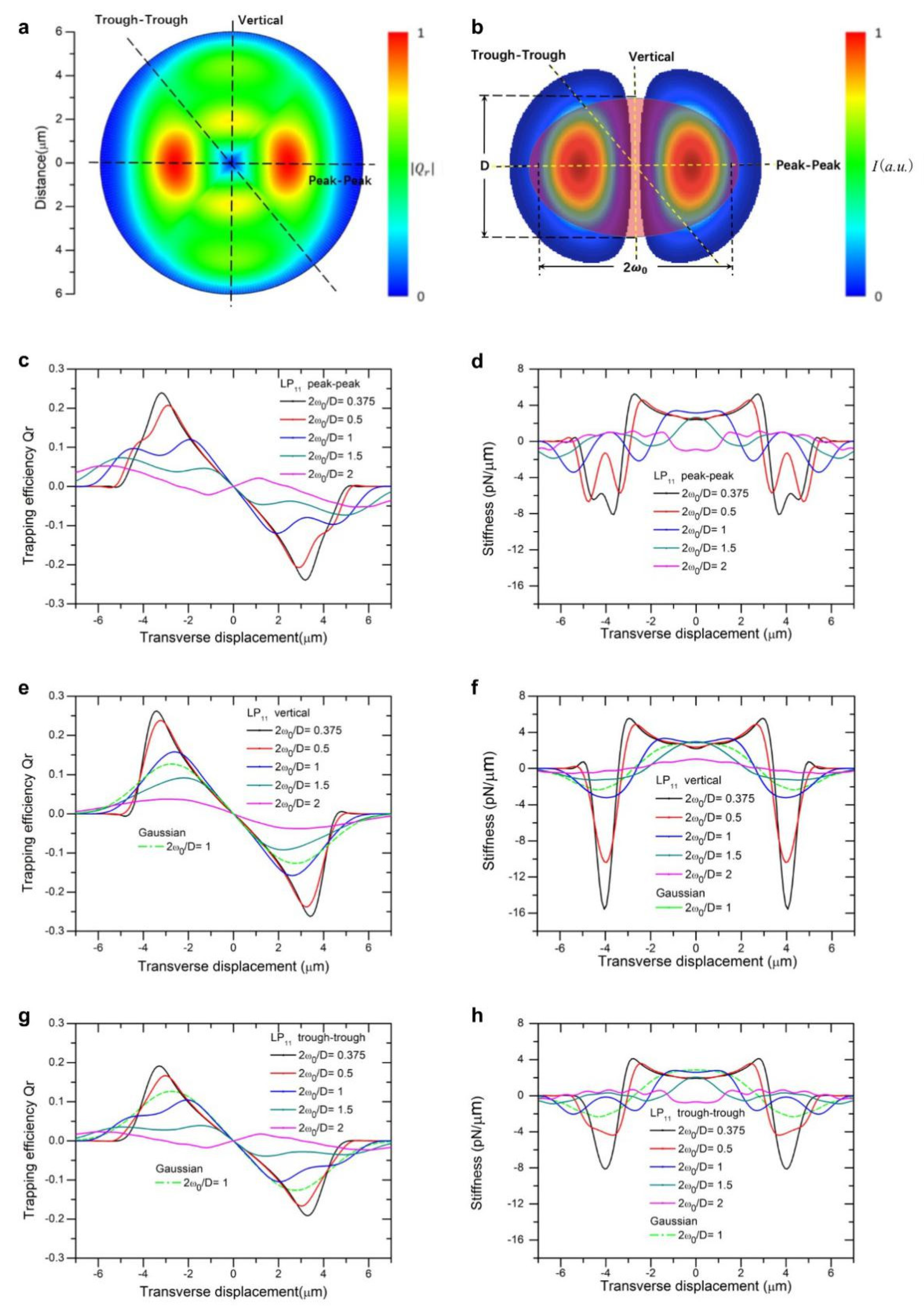
Figure 1a,
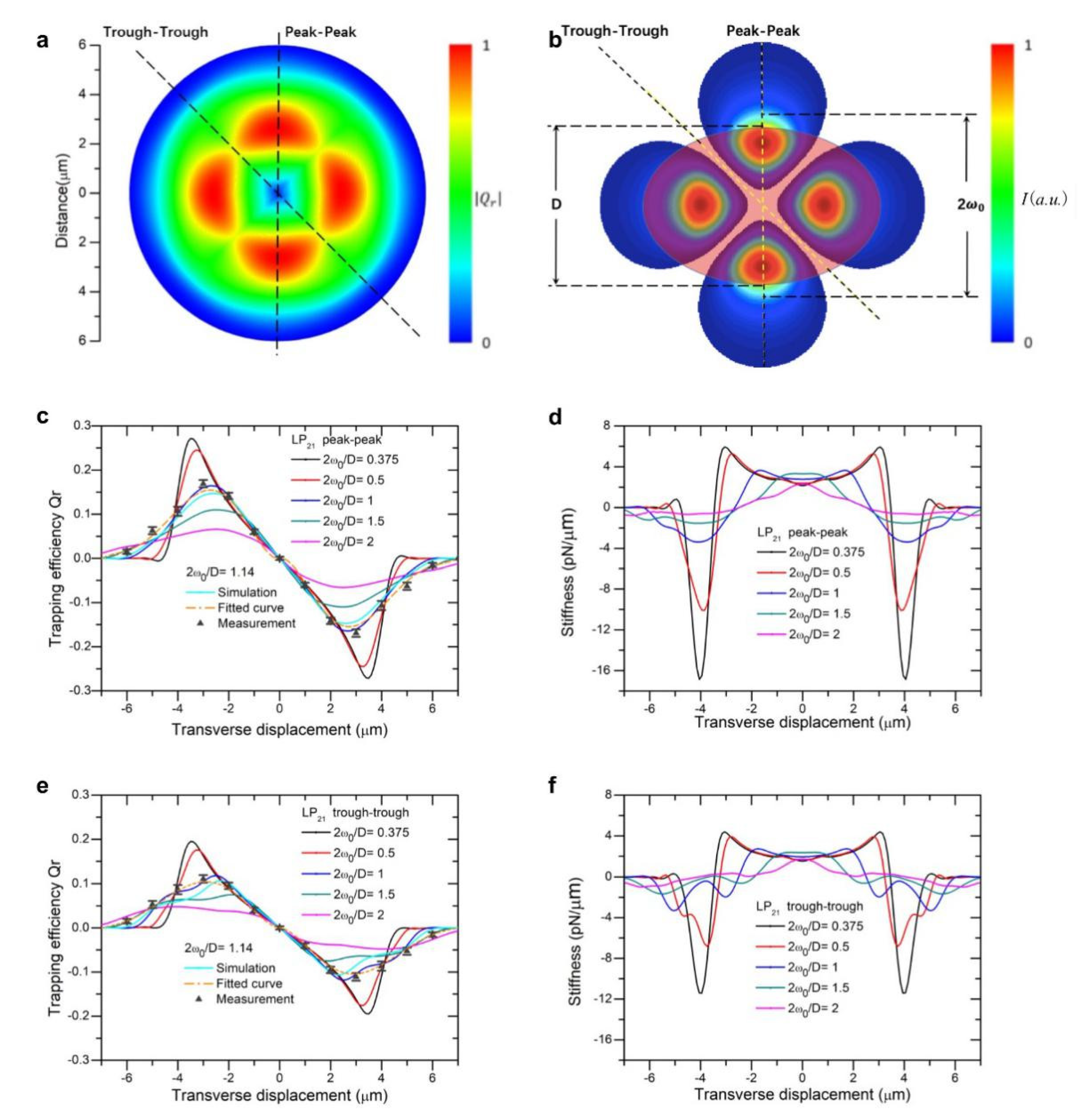
Figure 2a and
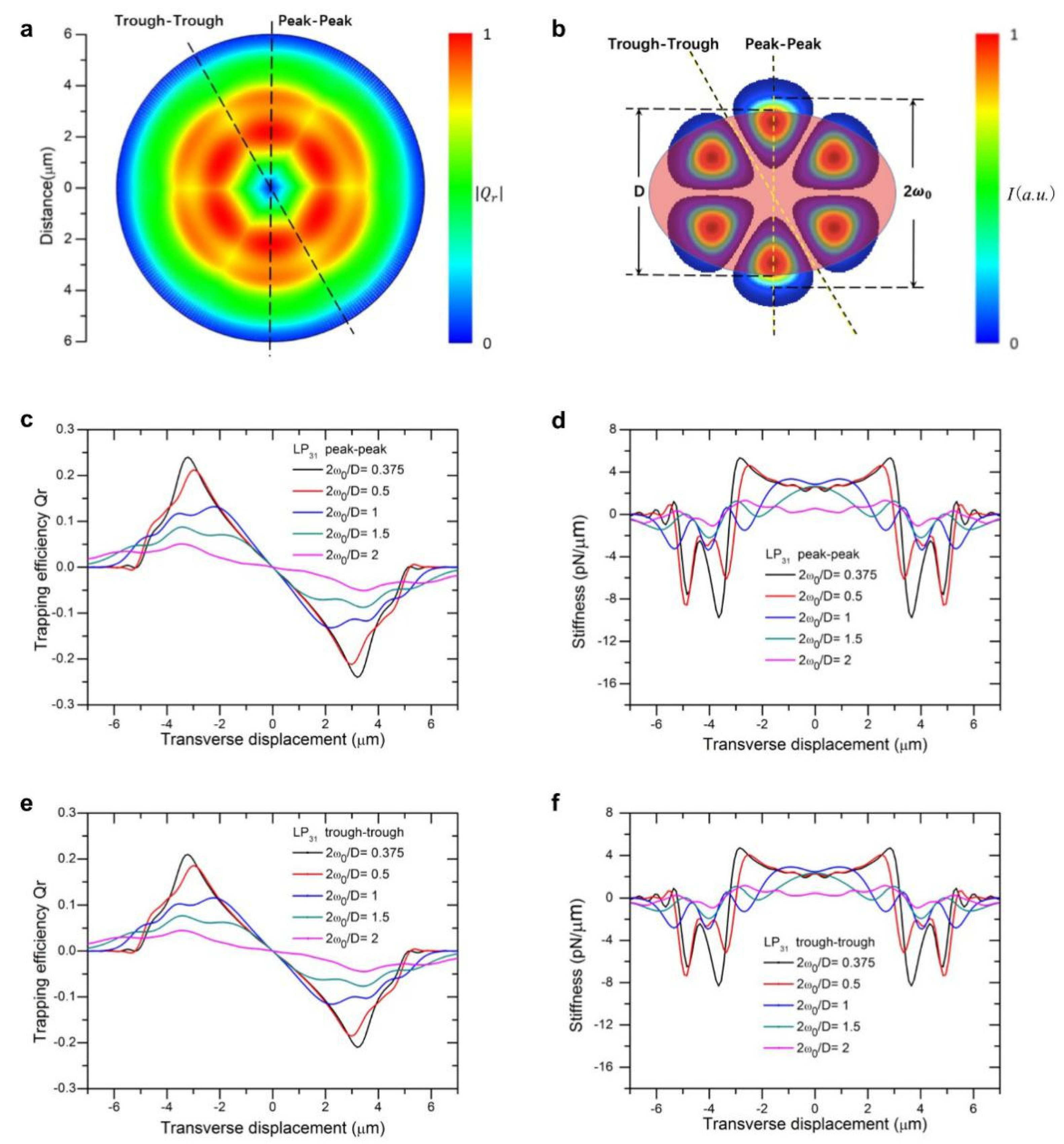
Figure 3a show the two-dimensional landscape of trapping efficiencies (absolute value) generated by beam of LP
11, LP
21, and LP
31 mode, respectively (eccentricity of spheroid is set at 1.31, 2
ω0/
D = 1.14). Trapping efficiency is converted to trapping force by a multiplication factor of nP/c, with P being the beam power, c the speed of light, and n refractive index of suspension liquid. For these high-order modes, beam size 2
ω0 was defined as the double distance from the beam axis where the intensity drops to 1/e
2 (≈13.5%) of the maximum value, the same as that for a LP
01 Gaussian beam. Laser power was set to be 10 mW in the following for stiffness calculations and wherever a light power input was necessary.
For different ratios of beam to particle size, we plot trapping efficiencies and stiffness as a function of displacement from beam center along two directions, peak-to-peak, vertical and trough-to-trough, as indicated in
Figure 1b,
Figure 2b and
Figure 3b using axial symmetry of beam profile overlaid with the particle. Compared with a Gaussian beam of the same size, the maxima of trapping force is close to those of modes LP
11 (2
ω0/D = 1, green dotted line in
Figure 1e,f), yet the force curve exhibits ripples along the peak-to-peak direction, owing to restoring forces acting on the particle by two inline traps consecutively when the particle is displaced, as shown in
Figure 1c,d. The maximum trapping force increases with decreasing ratio of beam size to particle size, as expected for high intensity beams. Along the vertical direction, peak trapping force is slightly higher than that along the peak-to-peak direction (
Figure 1c verses
Figure 1e), attributable to simultaneous action of two traps formed by LP
11 mode field. But an interesting feature about these inline two traps is that trapping force in the vertical direction beyond maxima falls off much faster than that in the peak-to-peak direction, for the reason that action of trap force ceases soon after overlap reduces between particle and two traps, see
Figure 1e for 2
ω0/D = 1, 0.5, and 0.375. It is also noted that the calculated stiffness swings fast from positive to deeper negative peaks, shown in
Figure 1f as oppose to
Figure 1d. Close to the origin, trap stiffness continuously deviates from its value at the origin instead of holding constant, similar to the distribution of a focused Gaussian mode [
23]. In the peak-to-peak direction, stiffness curves dictate characteristics of trapping forces exerted by two separate traps simultaneously by LP
11 mode. When 2
ω0/D increases and exceeds 1, the width of trapping force becomes wider and peak value decreases significantly, which makes the capture and transport of particles not secured.
Figure 1g,h shows trapping efficiency and stiffness as a function of displacement along the trough-to-trough direction, where maxima trapping force is about 40% lower than those along the vertical direction.
For LP
21 mode,
Figure 2 displays the landscape of trapping forces and stiffness along two directions, trough-to-trough and peak-to-peak, parallel to the short axis of the particle. An LP
21 mode beam exhibits four lobes of field concentration regions, spheroid particle along the direction of the short axis overlaps less of the light field flux as compared with that in the direction of the long axis. We note that, for small beam sizes (2
ω0/D = 0.375, 0.5, and 1), stiffness fell from positive to negative values with fast slopes, as seen in
Figure 2d, and reached relatively large negative peaks. This can be attributed to the reason that one of the four light spots quickly breaks away from the overlap with the scattering particle as it is displaced in the peak-to-peak direction. While in the trough-to-trough direction, the trapping force and stiffness appear the lowest value, due to the successive reduction of overlapping areas between two of traps with the particle. Choosing one of the ratios of beam-to-particle size, 2
ω0/D =1.14, we experimentally validated whether the measured force curves in two directions are consistent with predictions based on T-matrix. We were able to fit the experimental data using numerical calculations based on the T-matrix method and found that data and theory are in good agreement (
Figure 2c,e).
The LP
31 mode exhibited higher axial symmetry of trapping efficiency and stiffness as compared with the previous two modes (
Figure 3a). Although
Qr decreases to a certain extent in the gaps between adjacent strong electric field distributions, the gap was much smaller than the particle size, and thereby little change in trapping forces or stiffness curves were observed. Therefore, the trapping force profiles along the two directions are fairly close, apart from that the peak value in the trough-trough direction was lower than that in peak-to-peak direction (
Figure 3c vs.
Figure 3e). Similar patterns were observed for trapping stiffnesses, as shown in
Figure 3d,f.
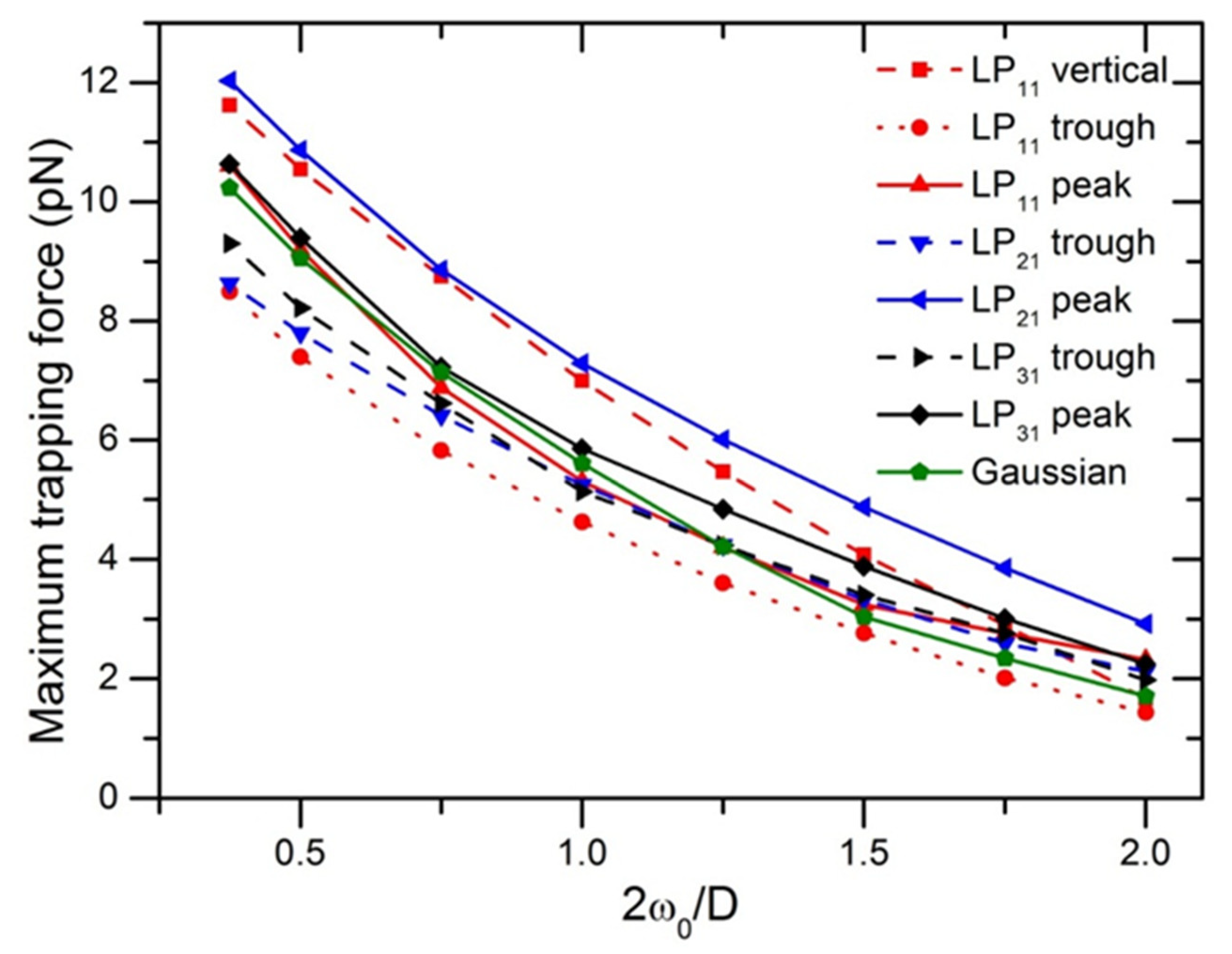
Figure 4 displays the maximum trapping force in different directions as a function of ratio of beam to particle size at the illumination power of P = 10 mW. The maximum magnitudes of F
max from the highest to the lowest, were obtained with LP
21, LP
11, LP
31, and LP
01 Gaussian modes, respectively. For LP
11 mode, displacing the particle along 45 directions with respect to the peak-to-peak direction, trapping force dropped about 36%, as can also be observed in the 2D force map in
Figure 1a. Trapping efficiency produced by LP
11 along the trough-to-trough direction is similar to that generated by LP
21 along the peak-to-peak direction, but the difference from each other increases with increasing 2
ω0/D, due to the two-lobed field distribution of LP
11. The four-lobed field of LP
21 mode surrounds a spheroid-shaped particle with a relative high stability. It is noted that F
max of a Gaussian beam as compared with that of other high-order modes, is in the middle of F
max values of other modes in different directions, as a result of axial symmetry.
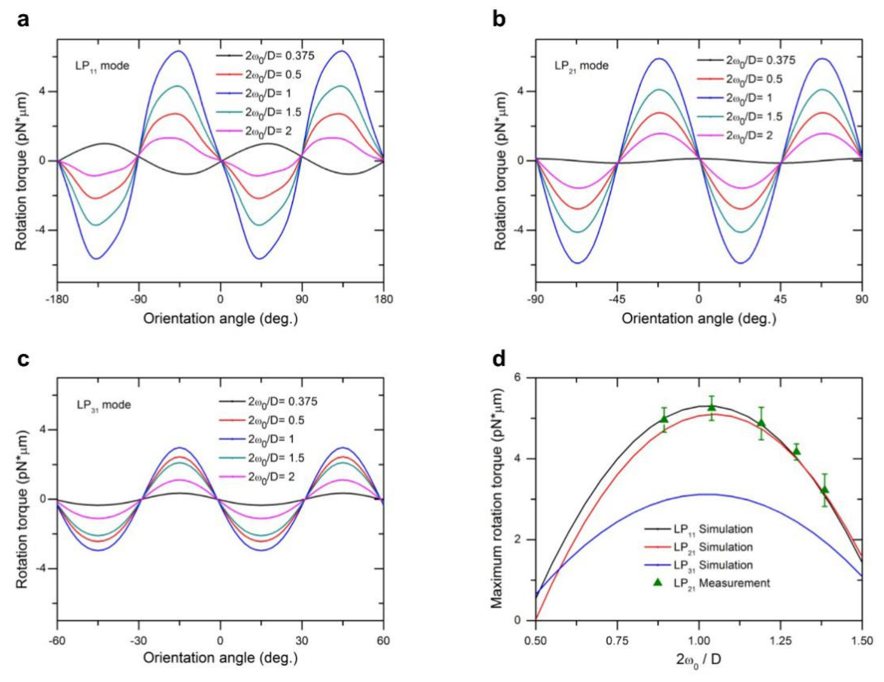
3.2. Controlled Rotational Manipulation by LP11, LP21, and LP31 Modes
Utilizing the T-matrix method, we also computed optical torque
Mz for LP
11, LP
21, and LP
31 modes, as shown in
Figure 5a–c, respectively, for different ratios of beam size to particle size. Depending on the orientation of the spheroid particle with respect to the light field distribution, optical torque exhibits distinct periodic peaks of either positive or negative values, representing the restoring torque driving the particle either clockwise or counterclockwise. The optical torque
Mz is zero when the long or short axis of a spheroid object aligns with either the peak-to-peak or trough-to-trough directions of field distribution of a high-order mode (with the exception of LP
11 mode, vertical direction instead of trough-to-trough direction), due to balanced pulling forces originating from multiple traps of the beam. When the orientation of the particle deviates from these symmetric directions, the optical torque will increase from zero, restoring the particle orientation back to the nearest equilibrium alignment. In
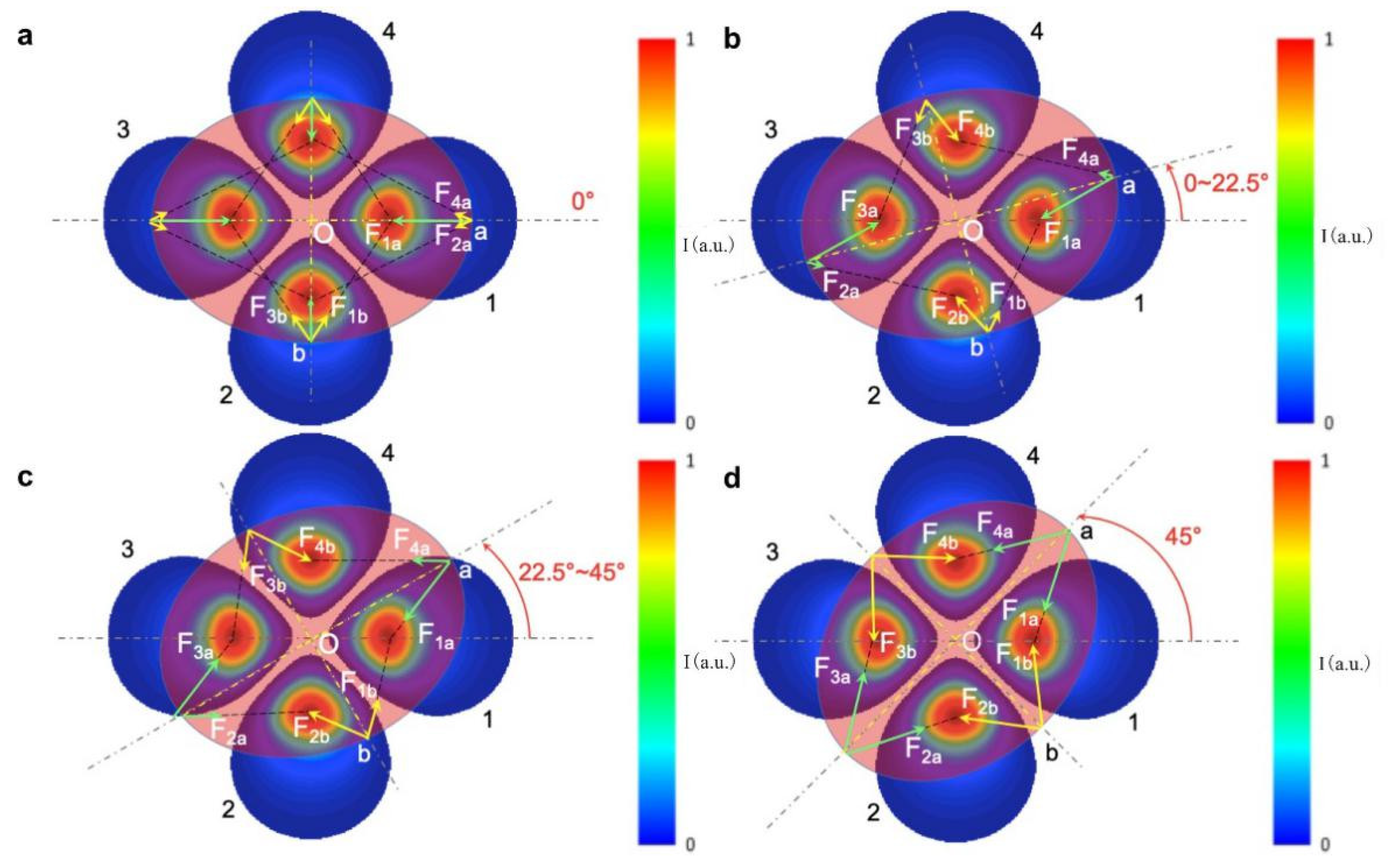
Figure 6 we depict these periodic torque curves as a function of orientation angles, using LP
21 mode as an example, where the mode field can be simplified to four centrosymmetric optical traps. At the orientation angle of 0 degrees, as shown in
Figure 6a, optical forces are along symmetric axes of the spheroid particle and the net torque is zero. For an orientation of 22.5 degrees or less (
Figure 6b), the LP
21 mode field produces a clockwise restoring torque. Because beam Spots 1 and 3 are close to two endpoints of the spheroid in the long axis, each exerts a pulling force F
1a or F
3a on the spheroid, which overcomes weak forces F
2a and F
4a and forms a net clockwise driving torque. The other two light spots (Spots 2 and 4) also play a role in torsion, but the torque is small because of little change in the overlap of light field with the particle. For orientation angles of between 22.5 and 45 degrees, as indicated in
Figure 6c, the overlap between beam spots with the spheroid decreases further, leading to a decrease of driving torque with increasing orientation angles. At 45 degrees, as indicated in
Figure 6d, the net torque returns to zero again due to symmetric configuration. This analysis applies to the cases of LP
11 and LP
31 mode field as well, except the period of zero torque changes to 90 and 30 degrees, respectively. It is interesting to note, for LP
11 mode, that the direction of the optical torque reverses for small beam sizes (2
ω0/D = 0.375) due to a good match of beam size with the short axis of the spheroid particle for the purpose of rotation.
Therefore, it can be seen from
Figure 5a–c that the maximum optical torques (or holding torque) occur between two adjacent symmetrical overlap configurations between the light field and spheroid particle. In
Figure 5d we examine the maximum optical torque as a function of beam to particle size ratio. We also observe that the LP
11 mode provides the maximum peak value of optical torque, while that of LP
21 is slightly lower, and the LP
31 mode is smaller still, retaining only 57% of the torque produced by the LP
11 mode under the same beam power. It is clear that the holding torque decreases with an increase in the axial symmetry of the light field, approaching zero for a Gaussian beam theoretically.
Under the same illumination conditions (laser power, beam waist, and other constraints), the LP
11 mode beam has more advantages when considering the maximum rotation torque, and the LP
31 mode has a shorter torque cycle (backlash) of 30° as opposed to 45° of LP
21 and 90° of LP
11. The LP
31 mode can realize particle rotation with a fast angular response in cyclical rotation operations. The LP
11 mode, though its propagation is subjected to various external effects including fiber bending, twisting, or vibration, is expected to outperform other modes in cell manipulation if the beam is stabilized using a SLM and proper algorithm [
18]. Overall, the LP
21 mode provides an optical torque nearly as much as that of the LP
11 mode, while retaining its advantages in applications requiring stable trapping and holding torque. As beam size as a function of 2
ω0/D increases to match the target particle size, the scattering of angular momentum as a result of rotating light field increases and correspondingly increases maximum torque. Further increases in beam size past the target particle size leads to leakage of incoming radiation, and the torque subsequently decreases after an optimal peak. The optimal range of 2
ω0/D is between 0.8 and 1.3, which offers an effective manipulation of both lateral transport and rotation of a single bioparticle with the same beam setup.
To experimentally validate peak optical torque (holding torque), a bioparticle in fluid can be rotated and maximum angular speed measured before it begins to slide instead of rotating with the light field. This is the point where the Stokes frictional torque of the liquid is equal to the holding torque. When the particle first begins rotating with a structured light field at an angular speed, the liquid-suspended spheroid-shaped bioparticle is hindered by viscous force of the suspension fluid, which is described by the following equation (also see
Supplementary Materials S2):
where resistive torque
Tz, a rotational counterpart of Stokes drag force, can be expressed as:
wherein
γ is a constant pertaining to form factors of the rotating object [
26] as:
where
η is the fluid viscosity,
I is the moment of inertia of the bioparticle,
Ai and
li describe form factors and axis lengths of the spheroid particle, respectively. By solving the differential Equation (7), rotation angle
φ can be expressed as a function of time as follows:
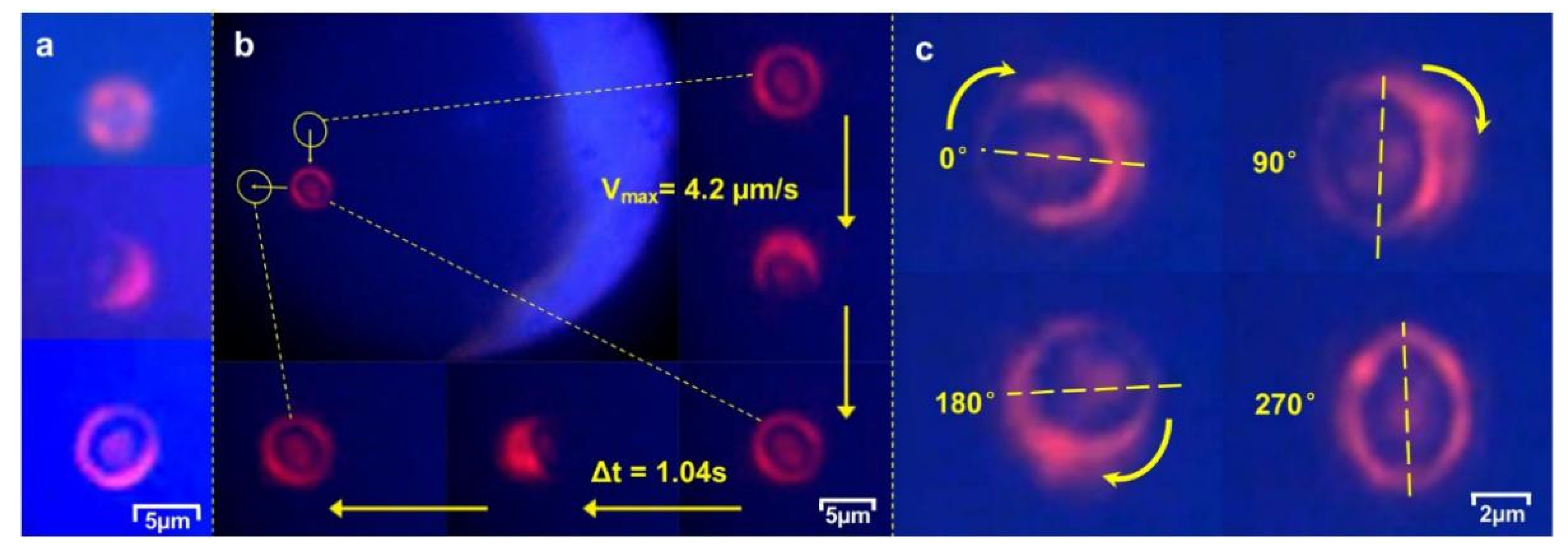
Upon trapping in the focused LP
21 beam, the yeast cell was immobilized by the four lobes of the laser beam. We further observed that a trapped cell was surrounded by a ring-like distribution of the light refracted and scattered by the cell (
Figure 7a, corresponding to before and after cell capture, respectiveln be expressed as a function of time as follows: fy). Within a fraction of a second, the long axis of the asymmetrically shaped cell was observed to rotate to align itself with a lobe peak-to-peak direction (as indicated in
Figure 2b) in a plane normal to the laser beam. The focused LP
21 beam also forms a stable trap along the beam direction, levitating the captured yeast cell inside a microfluidic channel as a 3D optical trap.
The measured result, shown in
Figure 5d, agrees well with that of the computed model. The experimental observations show that the holding torque of an LP
21 mode field not only offers an efficient tool for controlled rotation of single cells and secured trapping for cell transport in different directions, but also can maintain cell orientation during transport, as displayed in
Figure 7 and
Supplementary Materials (Videos S1 and S2). For a laser power as low as 10 mW, the peak speed in linear transport of single cell was 4.2 μm/s and peak rotation speed was 0.54 rad/s.
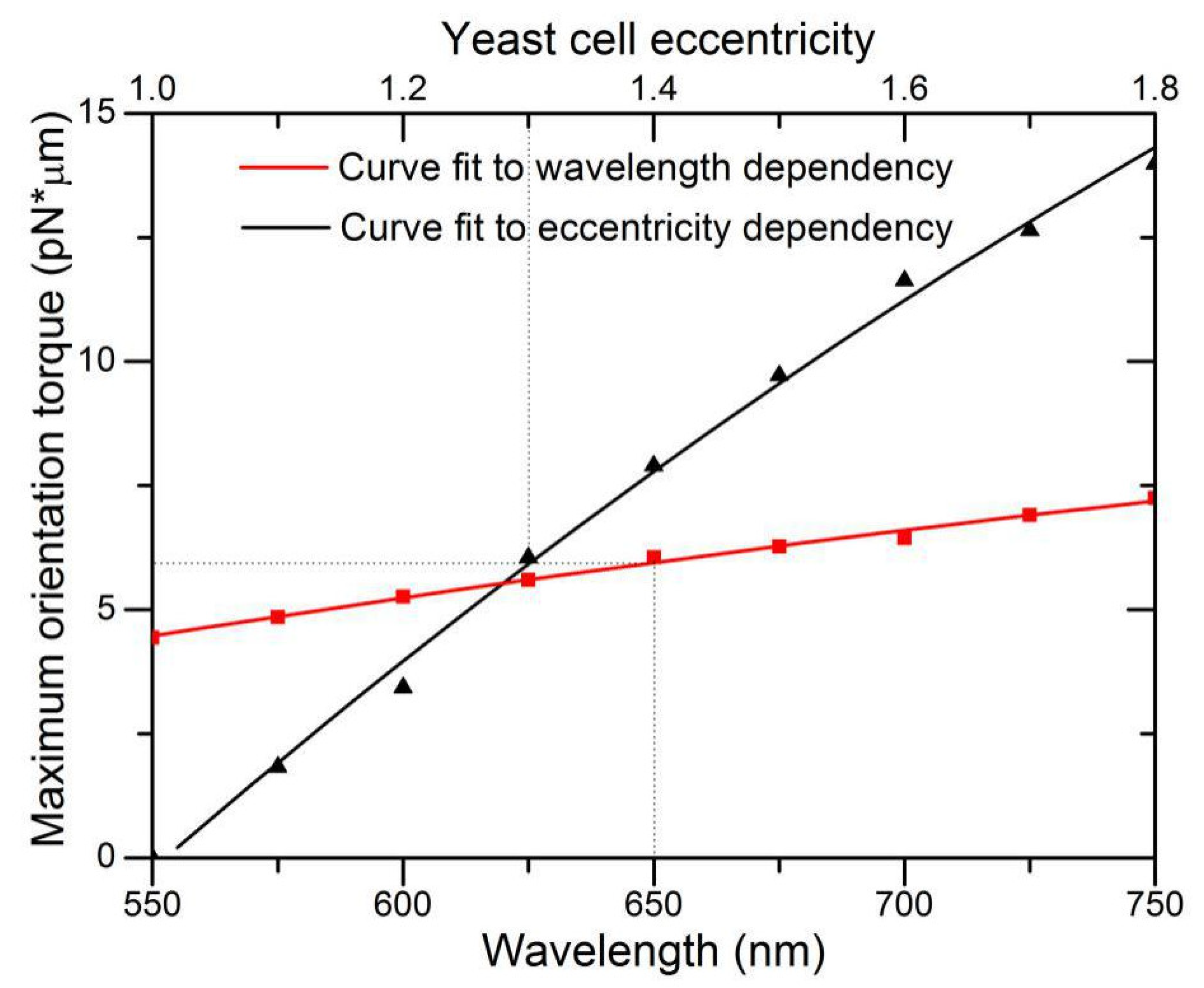
We also investigated the dependence of holding torque on wavelength and cell eccentricity. Under the illumination condition where LP
21 mode laser power P = 10 mW and beam size 2
ω0 = 4.8 μm, we varied the short axis length and fixed the long axis length at 5.8 μm for the spheroid particle, and then computed maximum rotation torque as a function of the eccentricity.
Figure 8 demonstrates a nearly linear increase in maximum rotation torque with eccentricity. As the short axis reduces in length, the interaction of the high-mode light field approaches the physics limit analogous to two light spots capturing a microrod at two ends, while the additional two light spots have little counteracting effect. This is also similar to the high effectiveness of rotation produced by a LP
11 mode beam. For wavelength dependence, optical torque is theoretically linearly proportional to wavelength owing to the factor of
P/ω to convert torque efficiency
τz to torque
Mz. However, the calculated result deviates slightly from linear dependence for the reason that the model T-matrix is approximated by a finite N
max terms of series expansion, thus, computation of all coefficients of
anm, bnm, pnm, and
qnm in Equation (6) are related to the size of wavelength-related domains.


 ,
, 


