
High-Precision Machining Method of Weak-Stiffness Mirror Based on Fast Tool Servo Error Compensation Strategy

Abstract
:1. Introduction
2. Error Compensation Strategy
2.1. Clamping Error Compensation Strategy
2.2. The Cutting Error Compensation Strategy
3. Simulation and Analysis
3.1. FTS Machining System
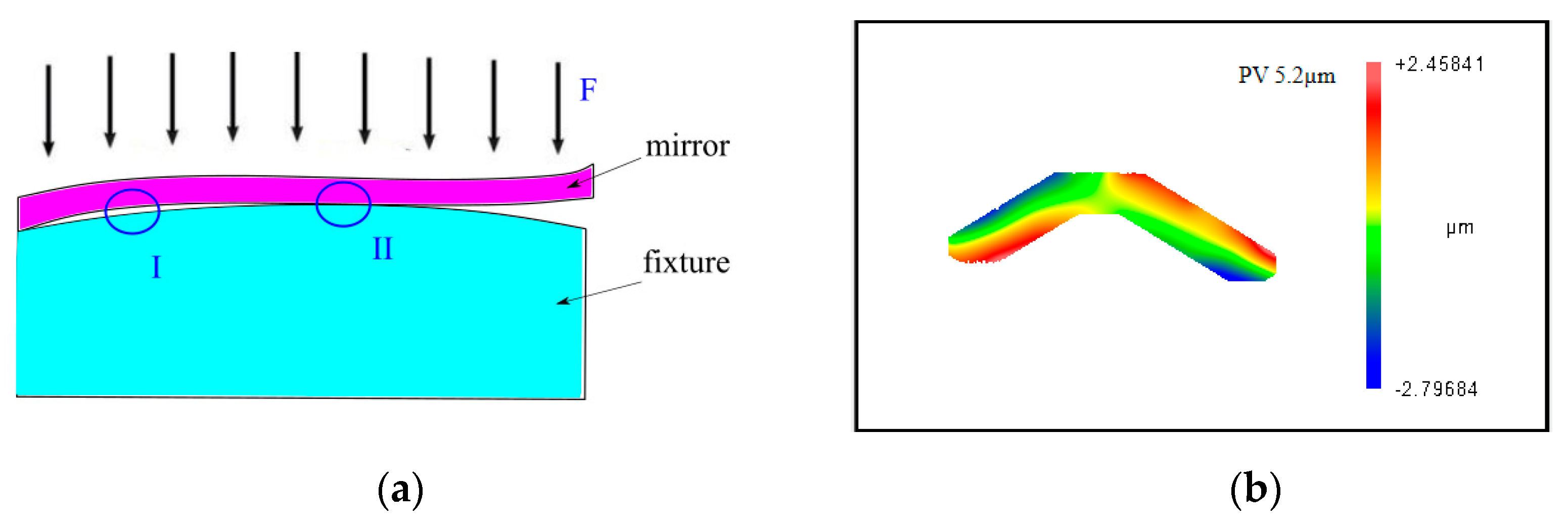
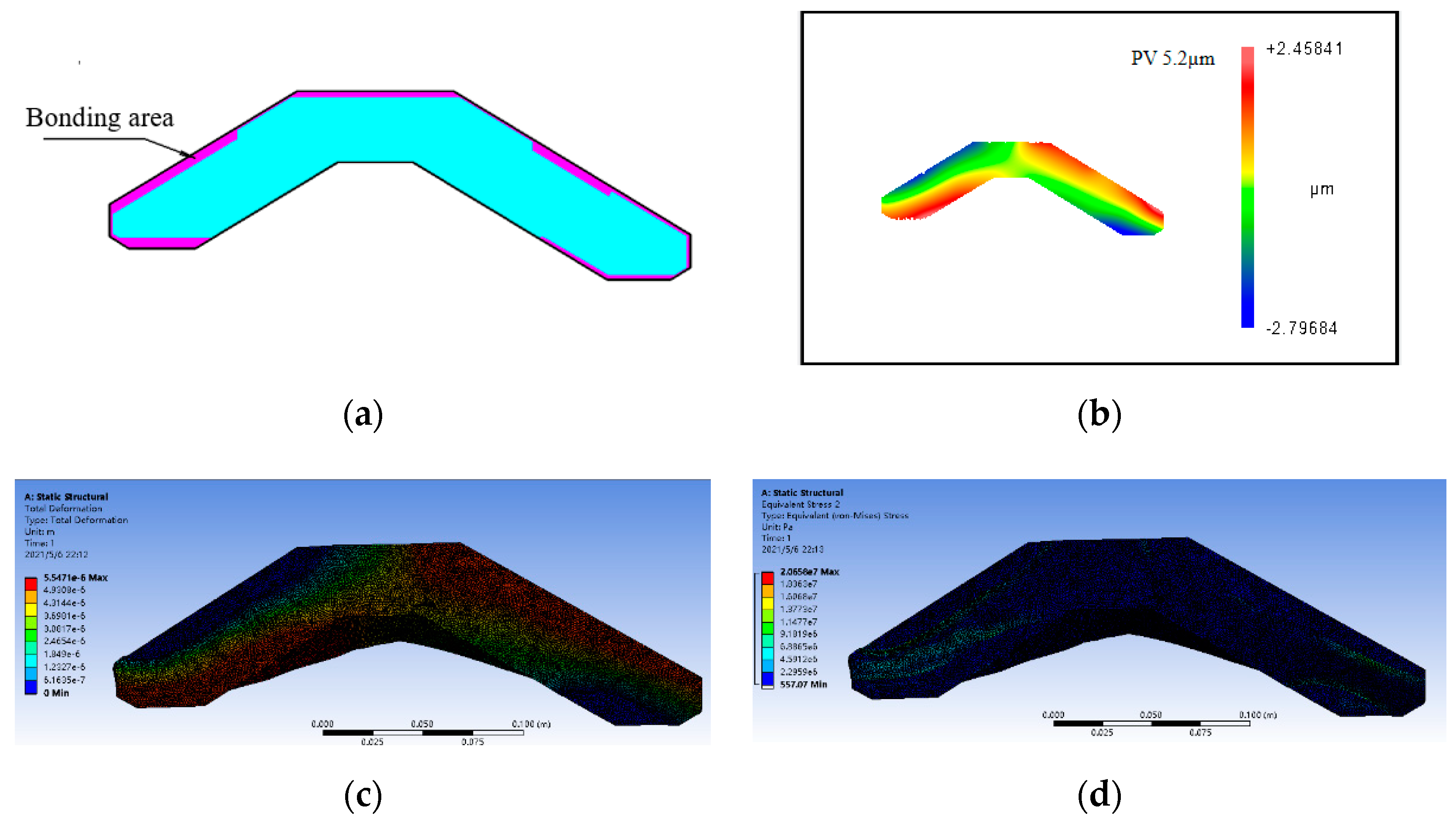
3.2. Clamping Deformation Simulation
3.3. The Analysis of Z-Axis Working Frequency
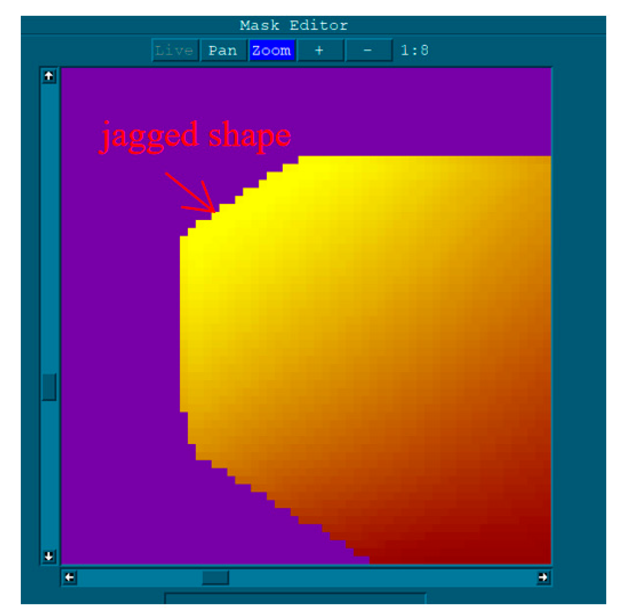
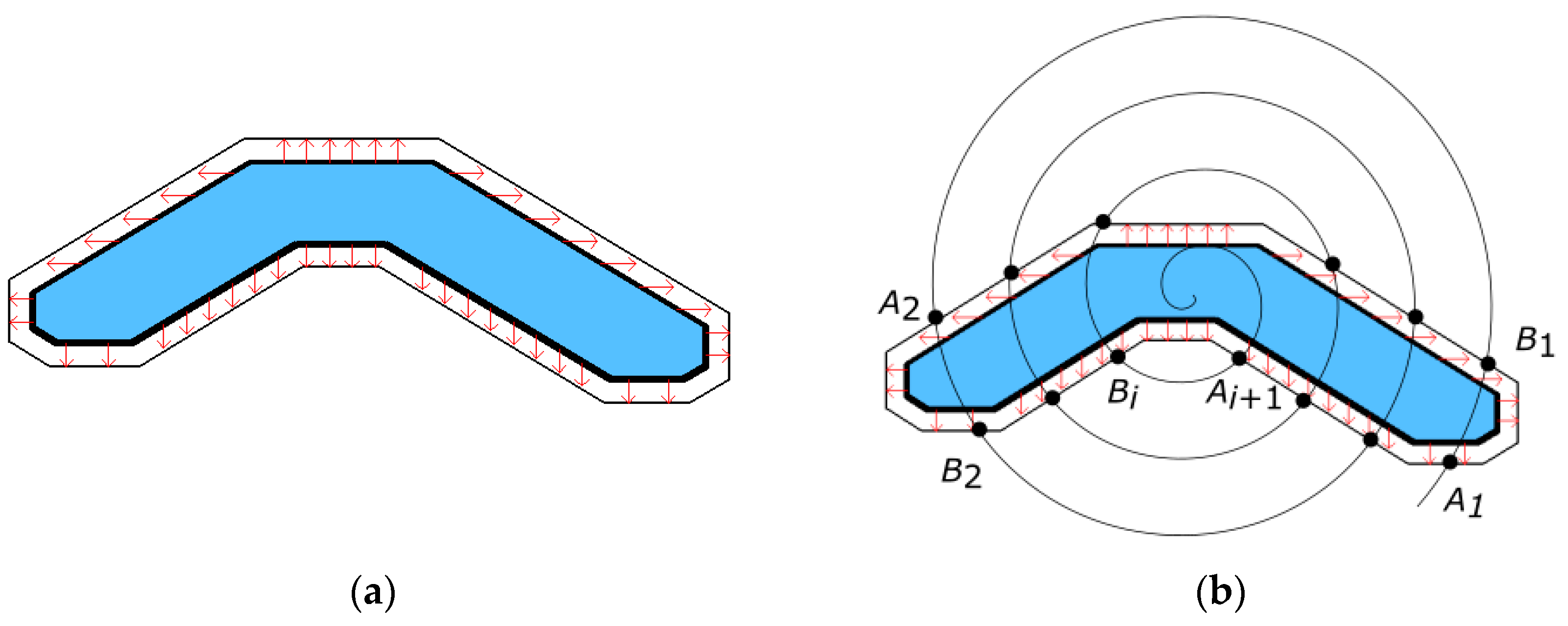
3.3.1. Spatial Curve Extension Algorithm
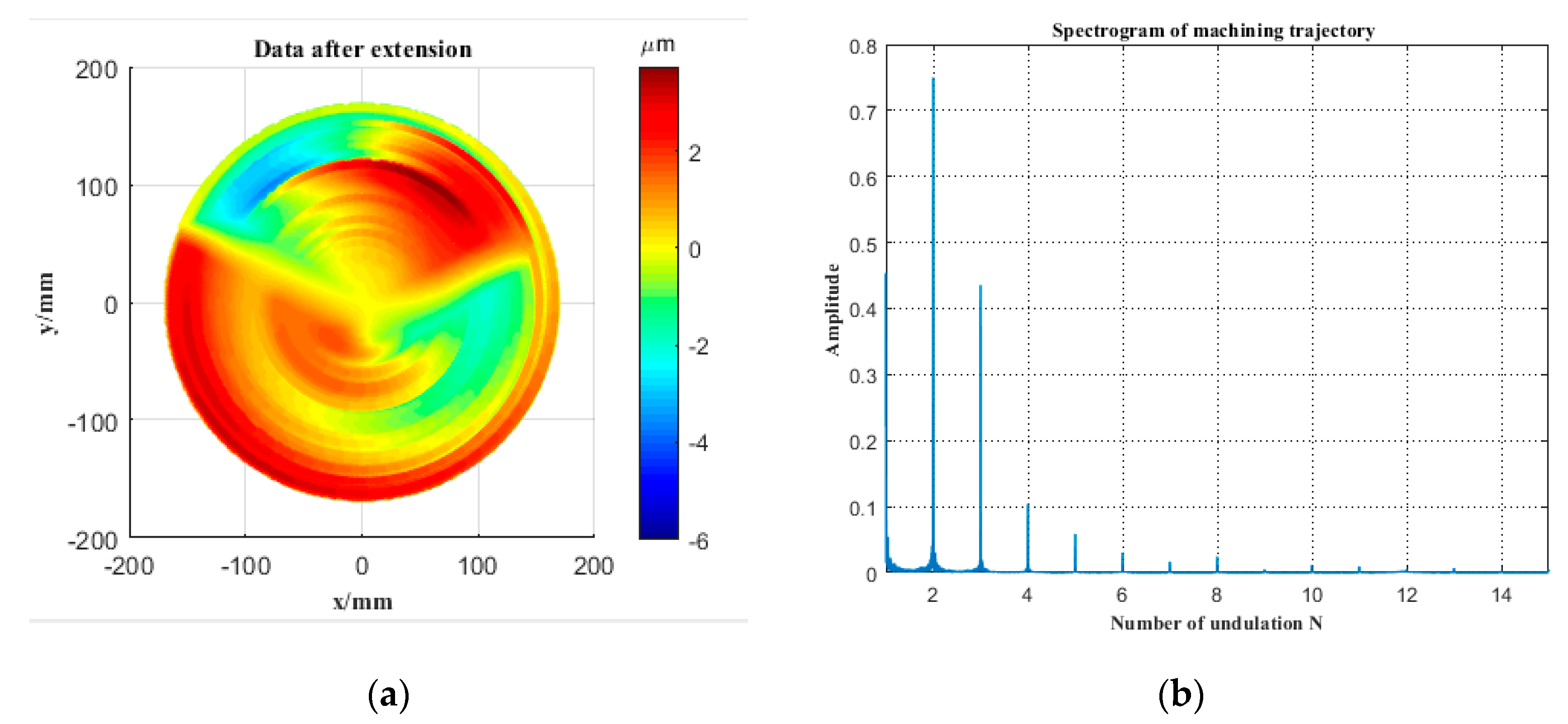
3.3.2. The Analysis of Z-Axis Working Frequency
4. Experimental Results and Discussion
4.1. Experimental Results
4.2. Discussion
- (1)
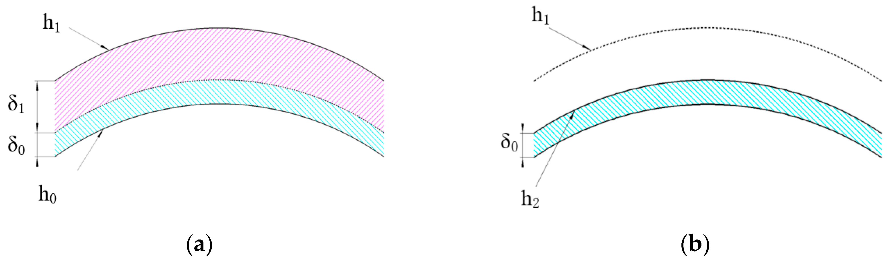
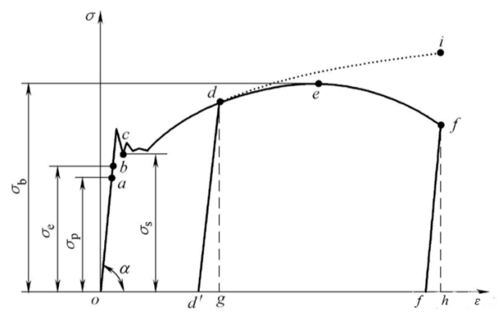
- In order to extract the elastic deformation of the mirror accurately, the compensation strategy proposed in this paper needs to control the clamping deformation in the elastic region. Through real-time monitoring and theoretical simulation, it ensures that the clamping deformation generated by each clamping is elastic. This method can be applied to most weak-stiffness mirrors. However, it may not be possible to control the clamping deformation in the elastic region for some mirrors that are very difficult to clamp or are very prone to plastic deformation. In this case, some adjustments can be made to the compensation strategy. First, the relationship between the elastic deformation δ1 and the plastic deformation δ0 needs to be obtained, as in Equation (11), and K is the scale factor. Then, based on Equation (11), the elastic deformation of the workpiece can still be obtained based on the measurement of the surface before clamping h0 and the surface after clamping h1, as in Equation (12) and Equation (13). The subsequent compensation strategy remains the same. To accurately obtain the scale factor K, we need to further investigate the elastic–plastic deformation theory.δ0 = Kδ1h1 − h0 = δ0 + δ1 = (1 + K)δ1δ1 = (h1 − h)/K
- (2)
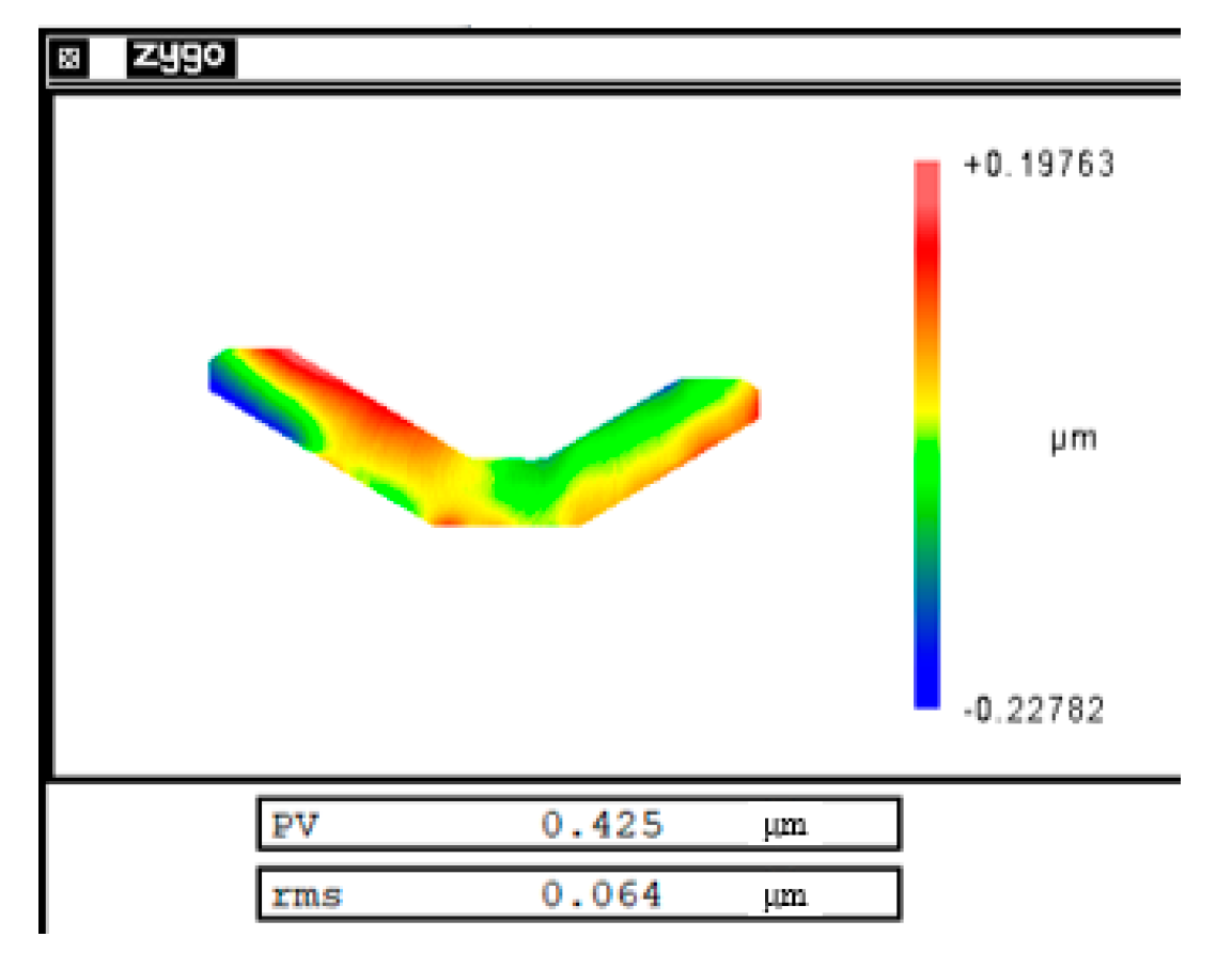
- In this paper, cutting errors are compensated by iterative machining. It was verified by repeatability experiments that the cutting errors were dominated by system errors under the same experimental conditions. Figure 17 shows the cutting error after compensation. The PV value of the cutting error was reduced from 1.6 µm to 0.4 µm. In order to maintain a good surface roughness on the machined surface, each machining time was about 2.5 h. During the second compensated machining, the machine condition was changed due to the long machining time and the change of the ambient temperature, which led to a large random error. It can be assumed that the residual error of the mirror surface was mainly the random error generated by the two machining processes. By reducing the machining time and controlling the ambient temperature to maintain the machine in a similar state during the two machining processes, the machining accuracy of the weak-stiffness mirror can be further improved.
- (3)
- This paper gives the calculation of the Z-axis working frequency at different spindle speeds, which is instructive. Different weak-stiffness mirrors produce different magnitudes and distributions of errors and require different Z-axis working frequencies. The researcher can select a suitable FTS system based on the calculation result of Equation (10).
5. Conclusions
Author Contributions
Funding
Conflicts of Interest
References
- Wang, H.; Wang, Z.; Wang, B.; Jin, Z.; Crassidis, J. Infrared Earth sensor with a large field of view for low-Earth-orbiting micro-satellites. Front. Inf. Technol. Electron. Eng. 2020, 22, 262–271. [Google Scholar] [CrossRef]
- Huang, Y.; Zhao, F.; He, M.; He, X. Research on the control technology of machining marks in double-side polishing of large aperture optical element. In Proceedings of the 9th International Symposium on Advanced Optical Manufacturing and Testing Technologies: Advanced Optical Manufacturing Technologies, Chengdu, China, 16 January 2018; p. 108381O. [Google Scholar] [CrossRef]
- Toubhans, B.; Fromentin, G.; Viprey, F.; Karaouni, H.; Dorlin, T. Machinability of inconel 718 during turning: Cutting force model considering tool wear, influence on surface integrity. J. Mater. Process. Technol. 2020, 285, 116809. [Google Scholar] [CrossRef]
- Ju, K.; Duan, C.; Kong, J.; Chen, Y.; Sun, Y.; Wu, S. Prediction of clamping deformation in vacuum fixtureworkpiece system for low-rigidity thin-walled precision parts using finite element method. Int. J. Adv. Manuf. Technol. 2020, 109, 1895–1916. [Google Scholar] [CrossRef]
- Chen, W.; Ni, L.; Xue, J. Deformation control through fixture layout design and clamping force optimization. Int. J. Adv. Manuf. Technol. 2008, 38, 860–867. [Google Scholar] [CrossRef]
- Pan, M.; Tang, W.; Xing, Y.; Ni, J. The clamping position optimization and deformation analysis for an antenna thin wall parts assembly with ASA, MIGA and PSO algorithm. Int. J. Precis. Eng. Manuf. 2017, 18, 345–357. [Google Scholar] [CrossRef]
- Miao, L.; Yu, H.; Cui, W.; Jiang, H.; Li, Y.; Wang, R.; Gao, X. Analysis and research of structure and process characteristic based on low rigidity shell part. In Proceedings of the the 7th International Conference on Mechanical and Electronics Engineering, Dalian, China, 26–27 September 2015; p. 03002. [Google Scholar] [CrossRef] [Green Version]
- Kong, L.B.; Cheung, C.F.; Kwok, T.C. Theoretical and experimental analysis of the effect of error motions on surface generation in fast tool servo machining. Precis. Eng. J. Int. Soc. Precis. Eng. Nanotechnol. 2014, 38, 428–438. [Google Scholar] [CrossRef]
- Penghao, R.; Aimin, W.; Long, W.; Dongxia, L. Simulation analysis of turning deformation of rotational thin-walled parts based on cutting force model. In Proceedings of the 2018 IEEE 9th International Conference on Mechanical and Intelligent Manufacturing Technologies, Cape Town, South Africa, 10–13 February 2018; pp. 21–25. [Google Scholar] [CrossRef] [Green Version]
- Laghari, R.; Li, J.; Mia, M. Effects of Turning Parameters and Parametric Optimization of the Cutting Forces in Machining SiCp/Al 45 wt% Composite. Metals 2020, 10, 840. [Google Scholar] [CrossRef]
- Zhang, L.; Sha, X.; Liu, M.; Wang, L.; Pang, Y. Cutting Force Prediction Models by FEA and RSM When Machining X56 Steel with Single Diamond Grit. Micromachines 2021, 12, 326. [Google Scholar] [CrossRef]
- Liu, X.; Zhang, X.; Fang, F.; Liu, S. Identification and compensation of main machining errors on surface form accuracy in ultra-precision diamond turning. Int. J. Mach. Tools Manuf. 2016, 105, 45–57. [Google Scholar] [CrossRef]
- Zhou, J.; Ren, J. Predicting cutting force with unequal division parallel-sided shear zone model for orthogonal cutting. Int. J. Adv. Manuf. Technol. 2020, 107, 4201–4211. [Google Scholar] [CrossRef]
- Li, D.; Qiao, Z.; Walton, K.; Liu, Y.; Xue, J.; Wang, B.; Jiang, X. Theoretical and Experimental Investigation of Surface Topography Generation in Slow Tool Servo Ultra-Precision Machining of Freeform Surfaces. Materials 2018, 11, 2566. [Google Scholar] [CrossRef] [PubMed] [Green Version]
- Liu, Y.; Zheng, Y.; Gu, Y.; Lin, J.; Lu, M.; Xu, Z.; Fu, B. Development of Piezo-Actuated Two-Degree-of-Freedom Fast Tool Servo System. Micromachines 2019, 10, 337. [Google Scholar] [CrossRef] [PubMed] [Green Version]
- Zhu, L.; Li, Z.; Fang, F.; Huang, S.; Zhang, X. Review on fast tool servo machining of optical freeform surfaces. Int. J. Adv. Manuf. Technol. 2018, 95, 2071–2092. [Google Scholar] [CrossRef]
- Kim, H.S.; Kim, E.J. Feed-forward control of fast tool servo for real-time correction of spindle error in diamond turning of flat surfaces. Int. J. Mach. Tools Manuf. 2003, 43, 1177–1183. [Google Scholar] [CrossRef]
- Kim, H.S.; Kim, E.J.; Song, B.S. Diamond turning of large off-axis aspheric mirrors using a fast tool servo with on-machine measurement. J. Mater. Process. Technol. 2004, 146, 349–355. [Google Scholar] [CrossRef]
- Yu, D.P.; Hong, G.S.; Wong, Y.S. Profile error compensation in fast tool servo diamond turning of micro-structured surfaces. Int. J. Mach. Tools Manuf. 2012, 52, 13–23. [Google Scholar] [CrossRef]
- Zhang, C.; Jiao, S.; Wang, L. Clamping deformation analysis and machining parameter optimization of weak stiffness ring parts. In Proceedings of the the 2nd International Conference on Frontiers of Materials Synthesis and Processing, Sanya City, China, 10–11 November 2019; p. 012028. [Google Scholar] [CrossRef]
- Li, Y.; Zhang, Y.; Lin, J.; Yi, A.; Zhou, X. Effects of Machining Errors on Optical Performance of Optical Aspheric Components in Ultra-Precision Diamond Turning. Micromachines 2020, 11, 331. [Google Scholar] [CrossRef] [Green Version]
- Demeter, E.C. Restraint Analysis of Fixtures Which Rely on Surface Contact. J. Eng. Ind. 1994, 116, 207–215. [Google Scholar] [CrossRef]
- Chen, Y.; Gao, J.; Deng, H.; Zheng, D.; Chen, X.; Kelly, R. Spatial statistical analysis and compensation of machining errors for complex surfaces. Precis. Eng. 2013, 37, 203–212. [Google Scholar] [CrossRef]
- Wagoner, R.H.; Lim, H.; Lee, M.G. Advanced Issues in springback. Int. J. Plast. 2013, 45, 3–20. [Google Scholar] [CrossRef]
- Wang, J.; Geng, S.M.; Zhang, L.Y.; Lu, Y.S. Finite element analysis and control of clamping deformation mechanism of thin-wall shell workpiece. Acta Armamentarii 2011, 32, 1008–1013. [Google Scholar] [CrossRef]


| Symbol | Meaning |
|---|---|
| z0 | the desired machining trajectory |
| z1 | the first machining trajectory |
| z1′ | the actual first machining trajectory |
| z2 | the second machining trajectory |
| z2′ | the actual second machining trajectory |
| z3 | the final equivalent machining trajectory |
| h0 | the mirror surface before clamping |
| h1 | the mirror surface after clamping |
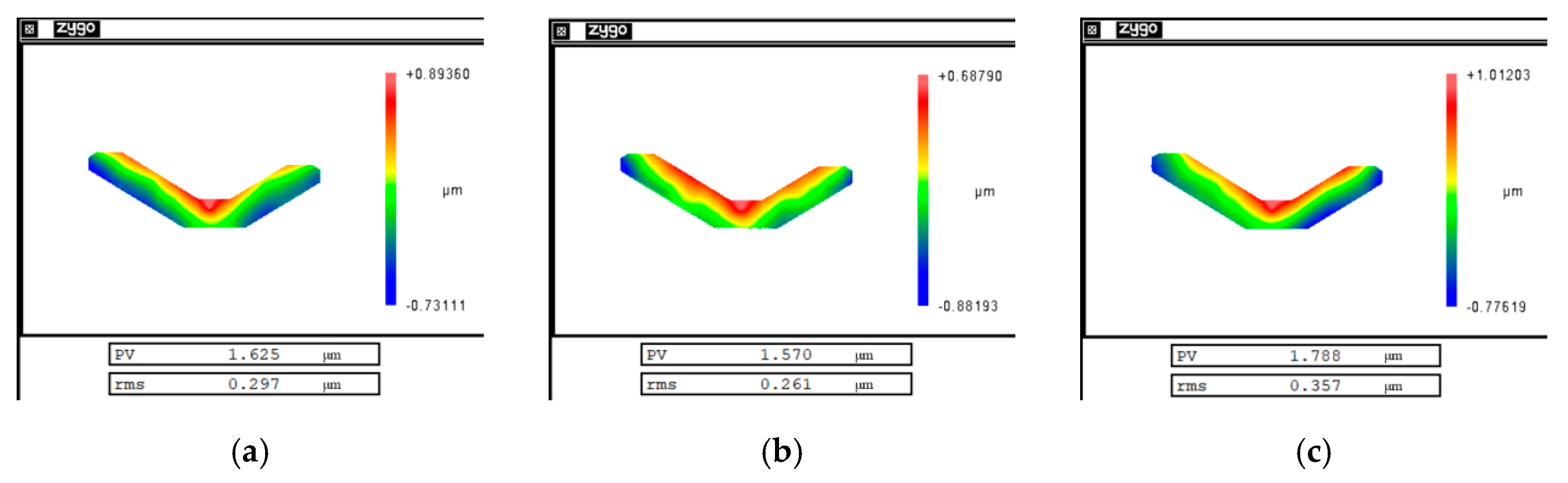
| Experimental Result | First Experiment | Second Experiment | Third Experiment |
|---|---|---|---|
| PV value | 1.625 µm | 1.570 µm | 1.788 µm |
| RMS value | 0.297 µm | 0.261 µm | 0.357 µm |
Publisher’s Note: MDPI stays neutral with regard to jurisdictional claims in published maps and institutional affiliations. |
© 2021 by the authors. Licensee MDPI, Basel, Switzerland. This article is an open access article distributed under the terms and conditions of the Creative Commons Attribution (CC BY) license (https://creativecommons.org/licenses/by/4.0/).
Share and Cite
Li, Z.; Dai, Y.; Guan, C.; Yong, J.; Sun, Z.; Du, C. High-Precision Machining Method of Weak-Stiffness Mirror Based on Fast Tool Servo Error Compensation Strategy. Micromachines 2021, 12, 607. https://0-doi-org.brum.beds.ac.uk/10.3390/mi12060607
Li Z, Dai Y, Guan C, Yong J, Sun Z, Du C. High-Precision Machining Method of Weak-Stiffness Mirror Based on Fast Tool Servo Error Compensation Strategy. Micromachines. 2021; 12(6):607. https://0-doi-org.brum.beds.ac.uk/10.3390/mi12060607
Chicago/Turabian StyleLi, Zelong, Yifan Dai, Chaoliang Guan, Jiahao Yong, Zizhou Sun, and Chunyang Du. 2021. "High-Precision Machining Method of Weak-Stiffness Mirror Based on Fast Tool Servo Error Compensation Strategy" Micromachines 12, no. 6: 607. https://0-doi-org.brum.beds.ac.uk/10.3390/mi12060607