
A Digitized Representation of the Modified Prandtl–Ishlinskii Hysteresis Model for Modeling and Compensating Piezoelectric Actuator Hysteresis


Abstract
:1. Introduction
2. Hysteresis Mathematical Model
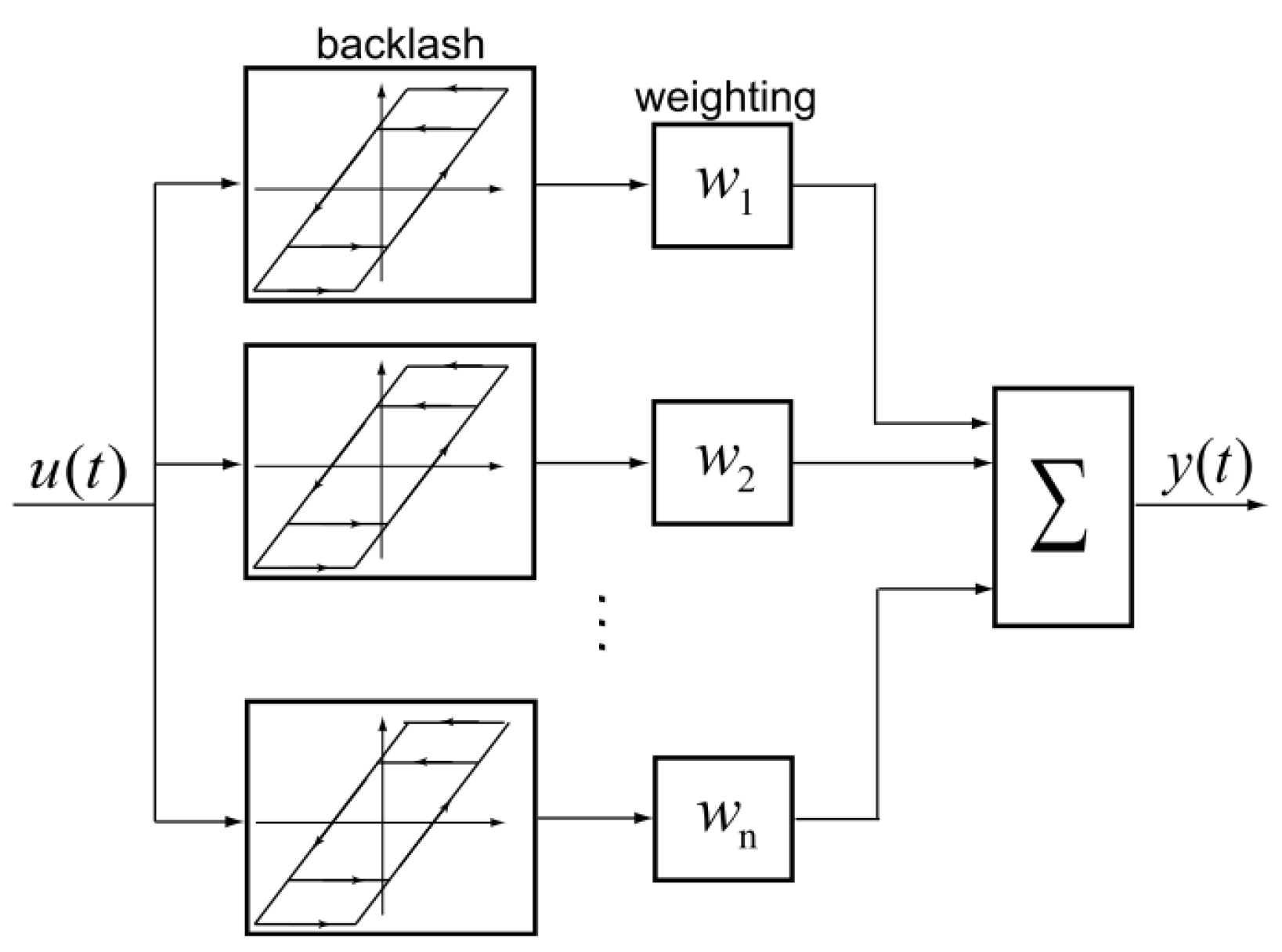
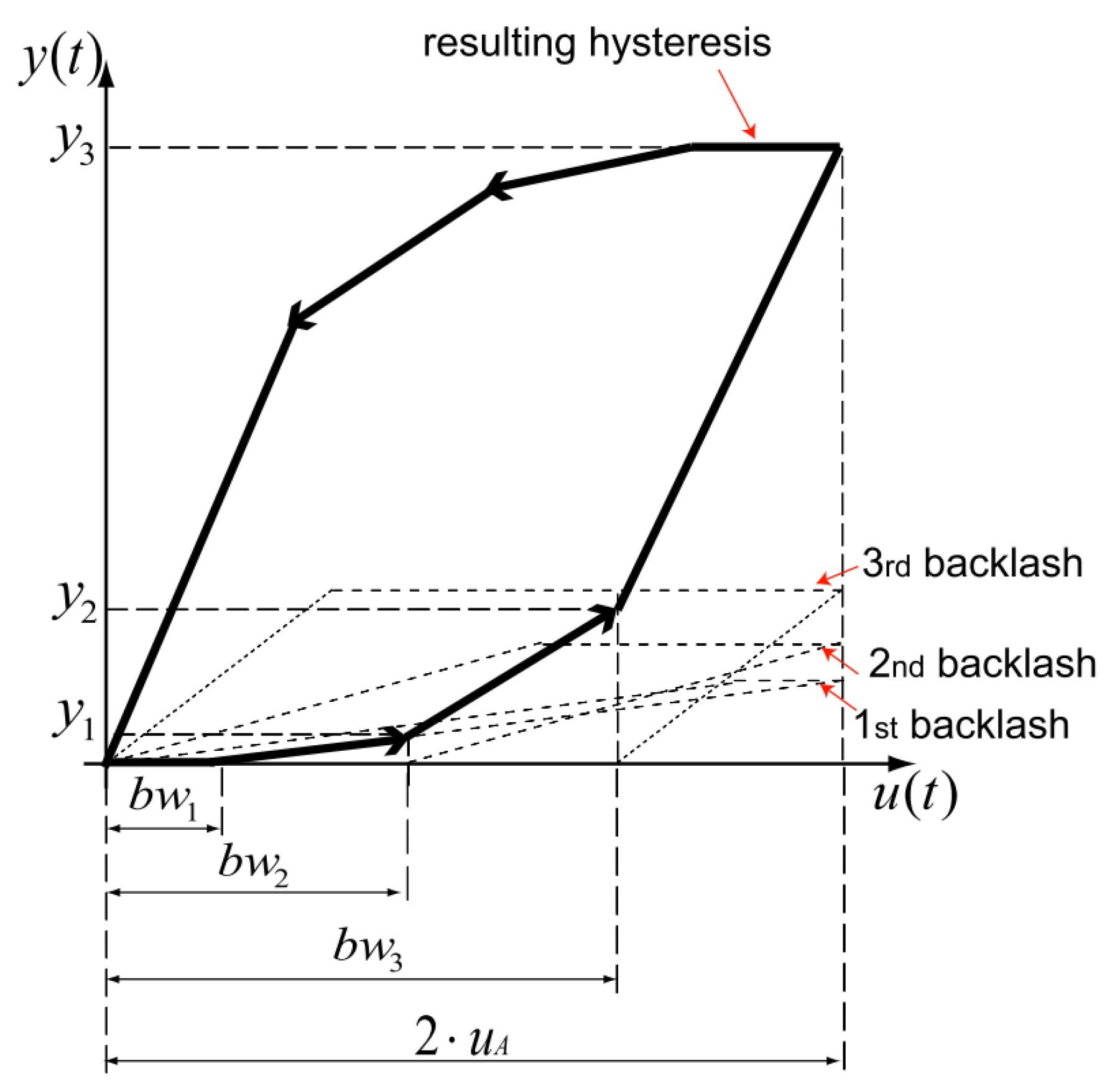
2.1. Classical PI Hysteresis Model
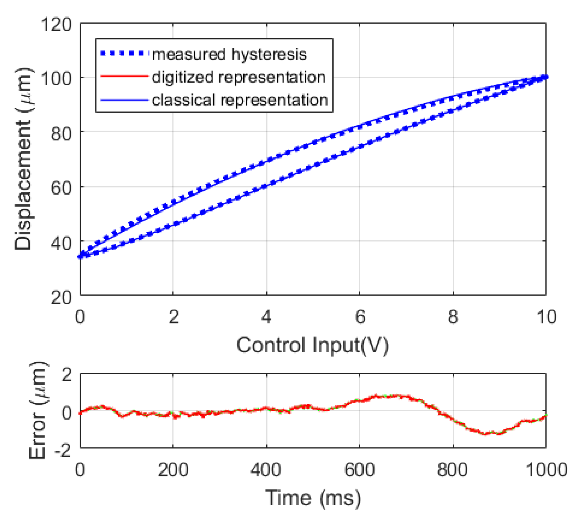
2.2. Digitized Classical PI Hysteresis Model
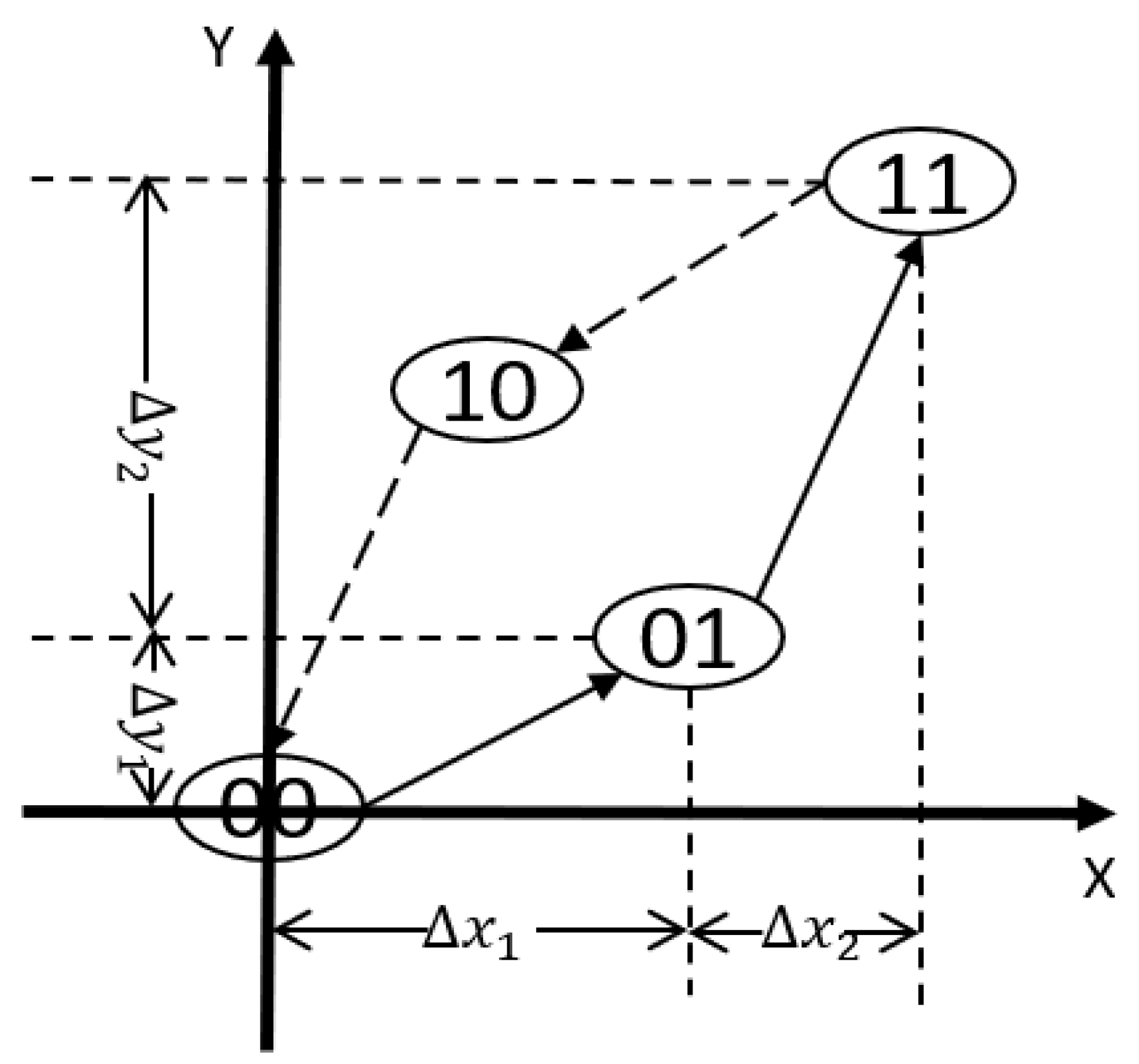
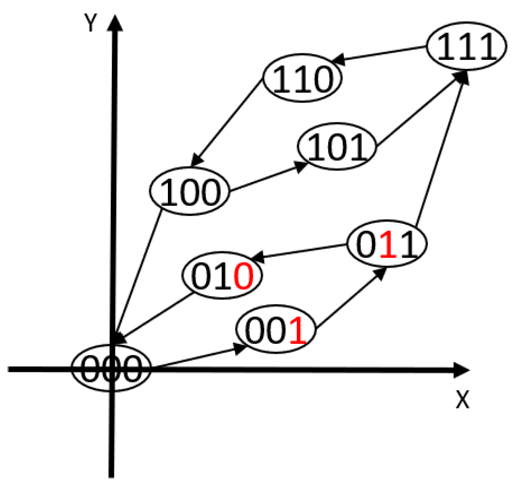
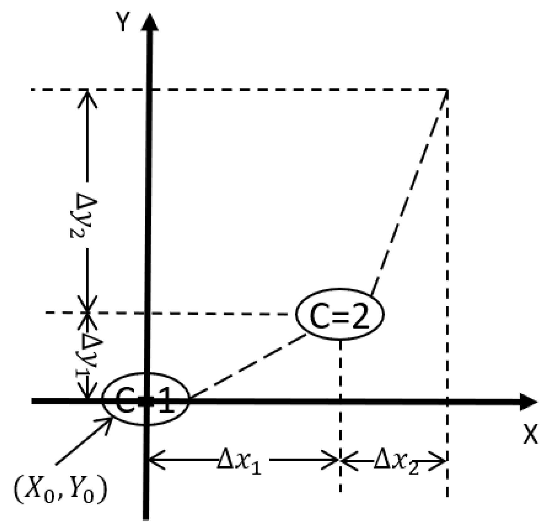
2.3. Digitized Dead-Zone Operators
- 1.
- If the system input value, x, is greater than or equal to and less than , the value of the system output y is calculated using (21).
- 2.
- If the system input value, x, is greater than and C is less than m, the state of the system is changed to its upper neighbor by increasing C, the is updated by adding . The procedure is then repeated.
- 3.
- If the system input value, x, is less than and C is greater than 1, the state of the system is changed to its lower neighbor by decreasing C, the is updated by subtracting . The procedure is then repeated.
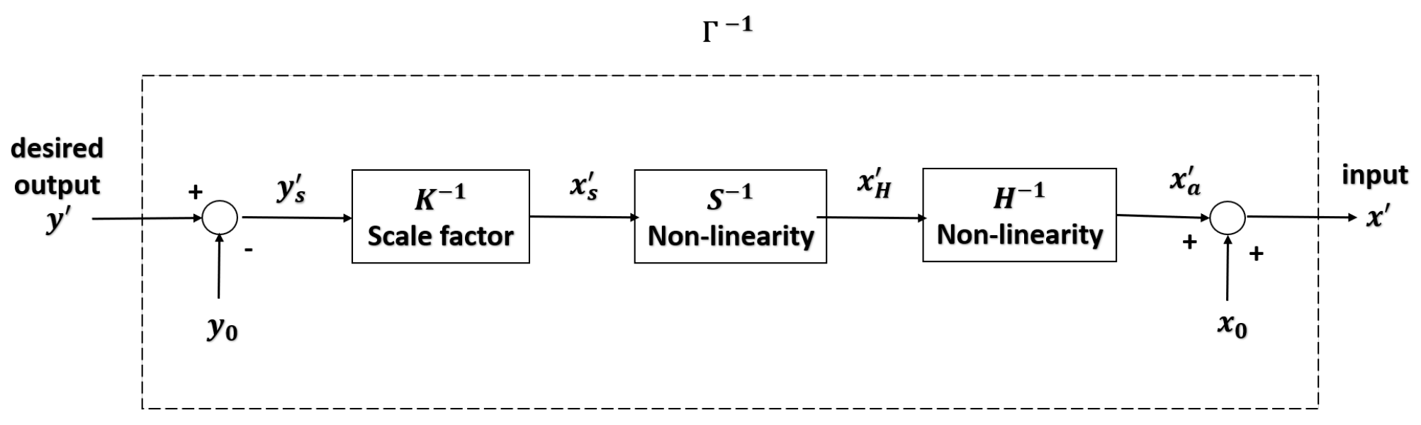
2.4. Inverse Model
3. Experimental Results
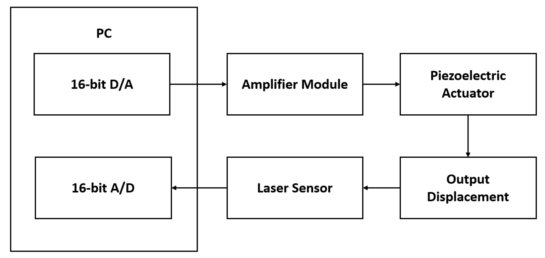
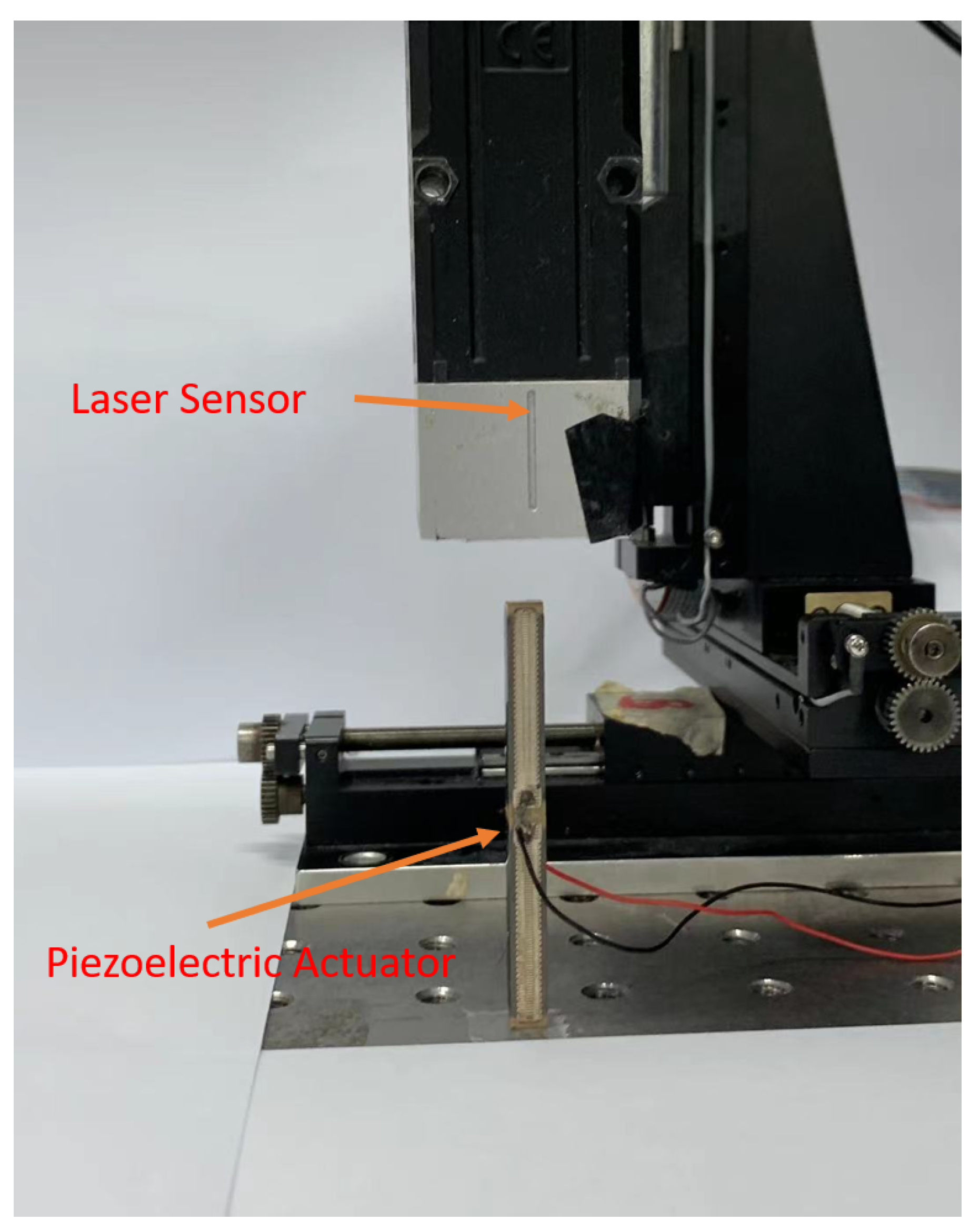
3.1. Experimental Setup
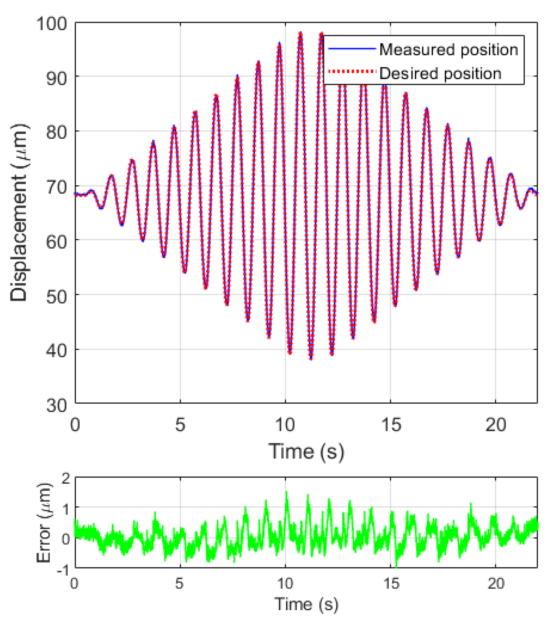
3.2. Experimental Results
3.3. Discussion
4. Conclusions
Author Contributions
Funding
Conflicts of Interest
References
- Latt, W.; Tan, U.X.; Shee, C.; Ang, W. A compact hand-held active physiological tremor compensation instrument. In Proceedings of the 2009 IEEE/ASME International Conference on Advanced Intelligent Mechatronics, Singapore, 14–17 July 2009; pp. 711–716. [Google Scholar]
- MacLachlan, R.A.; Becker, B.C.; Tabarés, J.C.; Podnar, G.W.; Lobes, L.A.; Riviere, C.N. Micron: An actively stabilized handheld tool for microsurgery. IEEE Trans. Robot. 2011, 28, 195–212. [Google Scholar] [CrossRef] [Green Version]
- Bravo-Zanoguera, M.E.; Laris, C.A.; Nguyen, L.K.; Oliva, M.; Price, J.H. Dynamic autofocus for continuous-scanning time-delay-and-integration image acquisition in automated microscopy. J. Biomed. Opt. 2007, 12, 034011. [Google Scholar] [CrossRef] [PubMed]
- Aguirre, A.D.; Sawinski, J.; Huang, S.W.; Zhou, C.; Denk, W.; Fujimoto, J.G. High speed optical coherence microscopy with autofocus adjustment and a miniaturized endoscopic imaging probe. Opt. Express 2010, 18, 4222–4239. [Google Scholar] [CrossRef] [PubMed] [Green Version]
- Chen, X.; Chen, Z.; Li, X.; Shan, L.; Sun, W.; Wang, X.; Xie, T.; Dong, S. A spiral motion piezoelectric micromotor for autofocus and auto zoom in a medical endoscope. Appl. Phys. Lett. 2016, 108, 052902. [Google Scholar] [CrossRef]
- Woronko, A.; Huang, J.; Altintas, Y. Piezoelectric tool actuator for precision machining on conventional CNC turning centers. Precis. Eng. 2003, 27, 335–345. [Google Scholar] [CrossRef] [Green Version]
- Okazaki, Y. A micro-positioning tool post using a piezoelectric actuator for diamond turning machines. Precis. Eng. 1990, 12, 151–156. [Google Scholar] [CrossRef]
- Abis, C.; Unal, F.; Mugan, A. Active vibration control with piezoelectric actuator on a lathe machine with a gain controller. In Proceedings of the 2011 IEEE International Conference on Mechatronics, Beijing, China, 7–10 August 2011; pp. 19–22. [Google Scholar]
- Junwu, K.; Zhigang, Y.; Taijiang, P.; Guangming, C.; Boda, W. Design and test of a high-performance piezoelectric micropump for drug delivery. Sens. Actuators A Phys. 2005, 121, 156–161. [Google Scholar] [CrossRef]
- Mori, K.; Munemoto, T.; Otsuki, H.; Yamaguchi, Y.; Akagi, K. A dual-stage magnetic disk drive actuator using a piezoelectric device for a high track density. IEEE Trans. Magn. 1991, 27, 5298–5300. [Google Scholar] [CrossRef]
- Chu, C.L.; Fan, S.H. A novel long-travel piezoelectric-driven linear nanopositioning stage. Precis. Eng. 2006, 30, 85–95. [Google Scholar] [CrossRef]
- Xie, S.L.; Liu, H.T.; Mei, J.P.; Gu, G.Y. Modeling and compensation of asymmetric hysteresis for pneumatic artificial muscles with a modified generalized Prandtl–Ishlinskii model. Mechatronics 2018, 52, 49–57. [Google Scholar] [CrossRef]
- Harrison, R.G. A physical model of spin ferromagnetism. IEEE Trans. Magn. 2003, 39, 950–960. [Google Scholar] [CrossRef]
- Haverkamp, R.; Reggiani, P.; Ross, P.J.; Parlange, J.Y. Soil water hysteresis prediction model based on theory and geometric scaling. Environ. Mech. Water Mass Energy Transf. Biosph. 2002, 129, 213–246. [Google Scholar]
- Zheng, J.; Li, Y.; Li, Z.; Wang, J. Transient multi-physics analysis of a magnetorheological shock absorber with the inverse Jiles–Atherton hysteresis model. Smart Mater. Struct. 2015, 24, 105024. [Google Scholar] [CrossRef]
- Knobloch, T.; Rzepa, G.; Illarionov, Y.Y.; Waltl, M.; Schanovsky, F.; Stampfer, B.; Furchi, M.M.; Mueller, T.; Grasser, T. A physical model for the hysteresis in MoS 2 transistors. IEEE J. Electron Devices Soc. 2018, 6, 972–978. [Google Scholar] [CrossRef]
- Yu, Y.; Zhang, C.; Wang, Y.; Zhou, M. Neural network-based iterative learning control for hysteresis in magnetic shape memory alloy actuator. IEEE/ASME Trans. Mechatron. 2021, 1. [Google Scholar] [CrossRef]
- Rakotondrabe, M. Bouc–Wen modeling and inverse multiplicative structure to compensate hysteresis nonlinearity in piezoelectric actuators. IEEE Trans. Autom. Sci. Eng. 2010, 8, 428–431. [Google Scholar] [CrossRef] [Green Version]
- Si, Z.Y.; Bai, X.X.; Qian, L.J.; Zhong, W.M. An enhanced Duhem model of magnetostrictive material-based actuators. In Behavior and Mechanics of Multifunctional Materials XIII; International Society for Optics and Photonics: Bellingham, WA, USA, 2019; Volume 10968, p. 1096818. [Google Scholar]
- Piatkowski, T. Dahl and LuGre dynamic friction models—The analysis of selected properties. Mech. Mach. Theory 2014, 73, 91–100. [Google Scholar] [CrossRef]
- Wu, Y.; Fang, Y.; Ren, X. A high-efficiency Kalman filtering imaging mode for an atomic force microscopy with hysteresis modeling and compensation. Mechatronics 2018, 50, 69–77. [Google Scholar] [CrossRef]
- Wu, Y.; Fang, Y.; Liu, C.; Fan, Z.; Wang, C. Gated recurrent unit based frequency-dependent hysteresis modeling and end-to-end compensation. Mech. Syst. Signal Process. 2020, 136, 106501. [Google Scholar] [CrossRef]
- Zhao, X.; Su, Q.; Chen, S.; Tan, Y. Neural network adaptive control of nonlinear systems preceded by hysteresis. J. Intell. Mater. Syst. Struct. 2021, 32, 104–112. [Google Scholar] [CrossRef]
- Song, G.; Zhao, J.; Zhou, X.; De Abreu-García, J.A. Tracking control of a piezoceramic actuator with hysteresis compensation using inverse Preisach model. IEEE/ASME Trans. Mechatron. 2005, 10, 198–209. [Google Scholar] [CrossRef]
- Li, Z.; Shan, J.; Gabbert, U. Inverse compensation of hysteresis using Krasnoselskii-Pokrovskii model. IEEE/ASME Trans. Mechatron. 2018, 23, 966–971. [Google Scholar] [CrossRef]
- Liu, Y.; Xie, S.; Du, D.; Qi, N. A Finite-Memory Discretization Algorithm for the Distributed Parameter Maxwell-Slip Model. IEEE/ASME Trans. Mechatron. 2020, 25, 1138–1142. [Google Scholar] [CrossRef]
- Al Janaideh, M.; Rakheja, S.; Su, C.Y. An analytical generalized Prandtl–Ishlinskii model inversion for hysteresis compensation in micropositioning control. IEEE/ASME Trans. Mechatron. 2010, 16, 734–744. [Google Scholar] [CrossRef]
- Yang, M.J.; Gu, G.Y.; Zhu, L.M. Parameter identification of the generalized Prandtl–Ishlinskii model for piezoelectric actuators using modified particle swarm optimization. Sens. Actuators A Phys. 2013, 189, 254–265. [Google Scholar] [CrossRef]
- Ang, W.T.; Khosla, P.K.; Riviere, C.N. Feedforward controller with inverse rate-dependent model for piezoelectric actuators in trajectory-tracking applications. IEEE/ASME Trans. Mechatron. 2007, 12, 134–142. [Google Scholar] [CrossRef] [Green Version]
- Tan, U.X.; Latt, W.T.; Shee, C.Y.; Riviere, C.N.; Ang, W.T. Feedforward controller of ill-conditioned hysteresis using singularity-free Prandtl–Ishlinskii model. IEEE/ASME Trans. Mechatron. 2009, 14, 598–605. [Google Scholar]
- Al Janaideh, M.; Mao, J.; Rakheja, S.; Xie, W.; Su, C.Y. Generalized Prandtl–Ishlinskii hysteresis model: Hysteresis modeling and its inverse for compensation in smart actuators. In Proceedings of the 2008 47th IEEE Conference on Decision and Control, Cancun, Mexico, 9–11 December 2008; pp. 5182–5187. [Google Scholar]
- Kuhnen, K. Modeling, identification and compensation of complex hysteretic nonlinearities: A modified Prandtl–Ishlinskii approach. Eur. J. Control 2003, 9, 407–418. [Google Scholar] [CrossRef]
- Gu, G.Y.; Yang, M.J.; Zhu, L.M. Real-time inverse hysteresis compensation of piezoelectric actuators with a modified Prandtl–Ishlinskii model. Rev. Sci. Instrum. 2012, 83, 065106. [Google Scholar] [CrossRef]
- Rakotondrabe, M. Classical Prandtl–Ishlinskii modeling and inverse multiplicative structure to compensate hysteresis in piezoactuators. In Proceedings of the 2012 American Control Conference (ACC), Montreal, QC, Canada, 27–29 June 2012; pp. 1646–1651. [Google Scholar]


Publisher’s Note: MDPI stays neutral with regard to jurisdictional claims in published maps and institutional affiliations. |
© 2021 by the authors. Licensee MDPI, Basel, Switzerland. This article is an open access article distributed under the terms and conditions of the Creative Commons Attribution (CC BY) license (https://creativecommons.org/licenses/by/4.0/).
Share and Cite
Zhou, C.; Feng, C.; Aye, Y.N.; Ang, W.T. A Digitized Representation of the Modified Prandtl–Ishlinskii Hysteresis Model for Modeling and Compensating Piezoelectric Actuator Hysteresis. Micromachines 2021, 12, 942. https://0-doi-org.brum.beds.ac.uk/10.3390/mi12080942
Zhou C, Feng C, Aye YN, Ang WT. A Digitized Representation of the Modified Prandtl–Ishlinskii Hysteresis Model for Modeling and Compensating Piezoelectric Actuator Hysteresis. Micromachines. 2021; 12(8):942. https://0-doi-org.brum.beds.ac.uk/10.3390/mi12080942
Chicago/Turabian StyleZhou, Chao, Chen Feng, Yan Naing Aye, and Wei Tech Ang. 2021. "A Digitized Representation of the Modified Prandtl–Ishlinskii Hysteresis Model for Modeling and Compensating Piezoelectric Actuator Hysteresis" Micromachines 12, no. 8: 942. https://0-doi-org.brum.beds.ac.uk/10.3390/mi12080942