
An Analytical Energy Harvester Model for Interdigitated Ring Electrode on Circular Elastic Membrane

Institute of Applied Mechanics, National Taiwan University, Taipei 10617, Taiwan
*
Author to whom correspondence should be addressed.
Micromachines 2022, 13(1), 133; https://0-doi-org.brum.beds.ac.uk/10.3390/mi13010133
Submission received: 16 October 2021
/
Revised: 6 January 2022
/
Accepted: 13 January 2022
/
Published: 15 January 2022
Abstract
:Energy harvesters are devices that accumulate ambient vibrational energy from the environment, and for the time being, variable capacitance is the most widely used mechanism. Various designs were proposed to increase the power of such devices, and in particular, the interdigitated electrode (IDE) pattern is the mainstream. Nevertheless, most IDE designs focus merely on the parallel-type vibrations of electrodes. In this study, the performance of a novel harvester, which combined circular membrane and interdigitated ring electrodes (IRE), was investigated. This design allows the device to collect energy from the rotational structure motions of electrodes through the vibrating membrane. Besides, the circular structure provides a dense capacitive arrangement that is higher than that of the arrangement obtained using regular rectangular chips. The IRE diagram is composed of many capacitive rings, each of which harvests vibrated energy simultaneously. Three gaps (1, 10, and 100 μm) of the ring are investigated for the first four vibrational modes of the membrane to understand the effect of energy output. It is found that the energy outputs are approximately the same for the three gaps; however, rings with a wider gap are easier to manufacture in MEMS.
1. Introduction
The mechanism of variable capacitance is widely used in vibration energy harvesters (VEHs), such as reverse electrowetting [1,2], honeycomb [3], electrostatic levitation [4], and interdigitated electrode (IDE) devices. According to the movement direction of the electrode plates, variable capacitance can be classified into three types [5], namely in-plane overlap [6], in-plane gap-closing [7], and out-of-plane gap-closing [8]. The in-plane overlap harvester varies the overlap area between finger electrodes, the in-plane gap-closing one varies the gap between finger electrodes, and the out-of-plane gap-closing one varies the gap between two large electrode plates. It is noted that these harvesters focus merely on the parallel-type vibrations of adjacent electrodes manufactured on rectangular chips.
Among various structures of a variable capacitance, the IDE design is commonly used in microelectromechanical systems [9,10]. This design possesses two advantages. First, the fabrication process is simple because the design of the IDE pattern can be produced in a plane structure. Second, a high-density arrangement of electrodes can be achieved on a micro scale. Different from the IDE but endowed with the same advantages, there is a radial geometric pattern of interdigitated ring electrode (IRE) that was developed by NASA to provide a radially distributed electric field in a circular piezoelectric actuator [11]. To date, the IRE design is widely used in biotechnology and flow sensors [12,13,14]; however, little attention has been paid to the study of this pattern applied to energy harvesting.
Here, a novel harvester with variable capacitance is proposed. The harvester is composed of a flexible circular membrane and a metal conductor with a certain IRE pattern. This device enables the energy collection from the vibration of radial electrodes on the diaphragm rather than the parallel motions of adjacent electrodes. Moreover, our design has two advantages. First, for the sake of resonance, we are able to tune the natural frequency of the device by adjusting the tension force of the membrane to match the vibration frequency from the environment. Secondly, the flexible structure of this device can sustain larger deformation from the external force than a harvester, which uses piezoelectric material.
Since our harvester has high-density ringed electrodes, a computational process would be time-consuming by using the finite element method (FEM). As a result, the conformal mapping method, which transforms the non-uniform electric field into a uniform one, is employed so that we are able to quickly evaluate the electric field of the IRE and thus estimate the capacitance variation per cycle of the harvester.
In this paper, we propose a mathematical model to analytically investigate the performance of the energy harvester with the IRE on a circular membrane. Since the membrane vibration gives rise to the angle change between two adjacent electrodes, the harvester achieves charge–discharge behavior. In order to evaluate the ability of harvesting energy due to angle change in the rotational electrodes, we quantitatively compared the capacitive change in a capacitor using rotating electrodes (applied to the circular membrane) with that using non-rotating electrodes (applied to the rectangular chip). Furthermore, the power density of our harvester is discussed in the case of a capacitive ring gap of 100 μm for 30 Hz vibration. Although this work is a theoretical discussion, our analysis provides useful information that pure experiments cannot offer. Such information includes the modal shape of the circular membrane and the angle profile of ringed electrodes on the deformed membrane, which enables us to find the optimal distribution of electrodes to raise the power of the harvester.
2. Mathematical Model
2.1. Vibration of Circular Membranes
We assume that a circular and symmetrical membrane is made of flexible elastic, and the vibration of the membrane can be modeled by the wave equation. By considering this membrane of radius R in Figure 1, the governing equation of vibration in the polar coordinate system (r, θ, z) can be expressed as
where u(r, t) is the displacement function of the membrane in the z-direction, which solely depends on the r-axis and time t. Here, c is the wave velocity, and f(r) and g(r) are the profiles of the initial deflection and initial velocity, respectively.
Equation (1) can be readily resolved using the separation of variables [15] as follows
where λm is the eigenvalue for the mth mode, and it comprises the wave velocity and wave number (λm = ckm = cαm/R). Wm(r) is the eigenfunction; J0 and J1 are the zeroth- and first-order Bessel functions of the first kind, respectively, and Am and Bm are the coefficients. The values of αm for the first four modes are listed in Table 1.
As depicted in Figure 1, the membrane, subjected to a pretension Tp and a mass M on the circular center, is supposed to have a tension T along the r direction. The velocity of the wave c can be expressed as c = (T/ρ)0.5, with the density of the membrane ρ. For simplicity, the initial deflection curve of the membrane is simulated by
where δ is the subsidence of the membrane center point. We assume the initial velocity g(r) = 0. Therefore, Equation (2) is simply written as
We are able to obtain the vibration of the membrane um in the mth normal mode by using Equation (4) as soon as R, c, and δ are specified.
2.2. Interdigitated Ring Electrode on the Circle Membrane
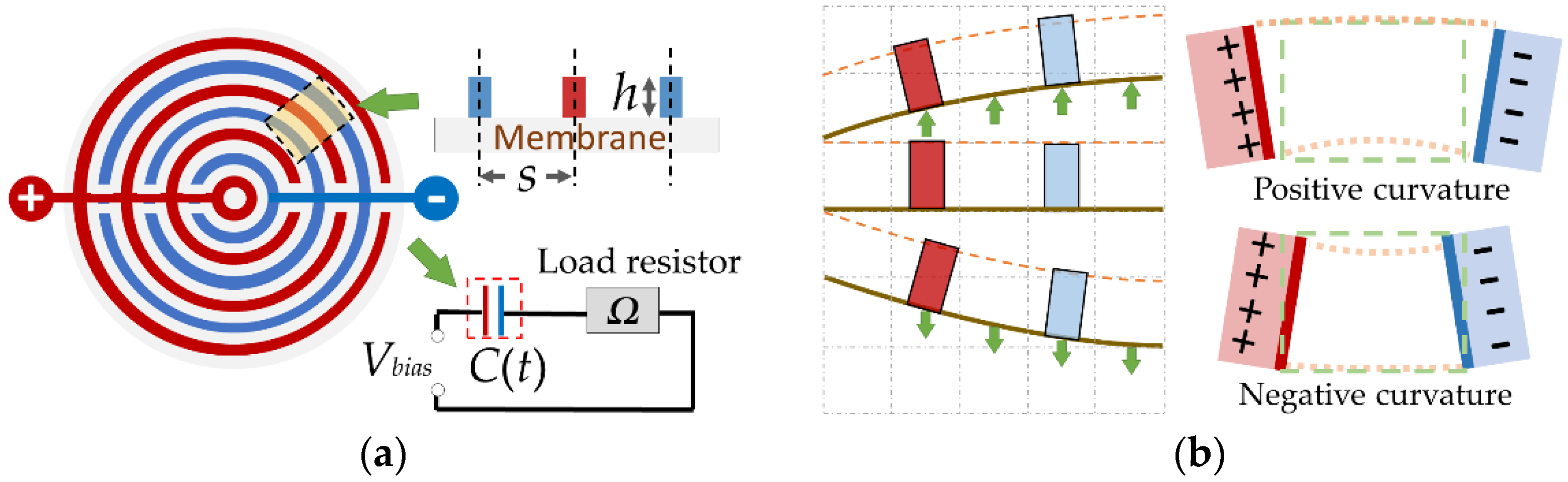
The IRE on the circular membrane consists of two electrode lines (denoted by the red and blue lines in Figure 2a). When applying the voltage Vbias, the loop, in Figure 2a, can be regarded as a resistor–capacitor equivalent circuit. The behavior of charge and discharge for the variable capacitor is from the capacitive change. That is why the IRE can harvest energy through membrane vibration.
Because the circular membrane is symmetrical, the deflection of the ring in the membrane is the same for any given radius r (independent on θ). Therefore, we assume that the circular membrane is cut into (R/s − 1) rings. Every ring contains a positive electrode and a negative electrode, thus forming a variable capacitor structure. The total length of the capacitance in a circular membrane is expressed as follows
where N = (R/s − 1). The parameter s represents the gap of the capacitive ring, and rn is the n-th radius.
2.3. Electrostatic Capacitance
The variable capacitance in the ring results in the formation of an inclined-plate capacitor when the membrane vibrates (Figure 2b). In order to calculate the electrostatic capacitance precisely, the method described in [16] is used for calculating the electrostatic capacitance per unit longitudinal length of an inclined plate,
where Cin is the internal capacitance inside angle φ per unit longitudinal length; Cout is the external capacitance outside angle ψ per unit longitudinal length (Figure 3); ε0 is the permittivity of vacuum; K(k) is the complete elliptic integral of the first kind; and kin, k′in, kout, and k′out are the modulus. In addition, the method assumes the width of the electrode is negligible.
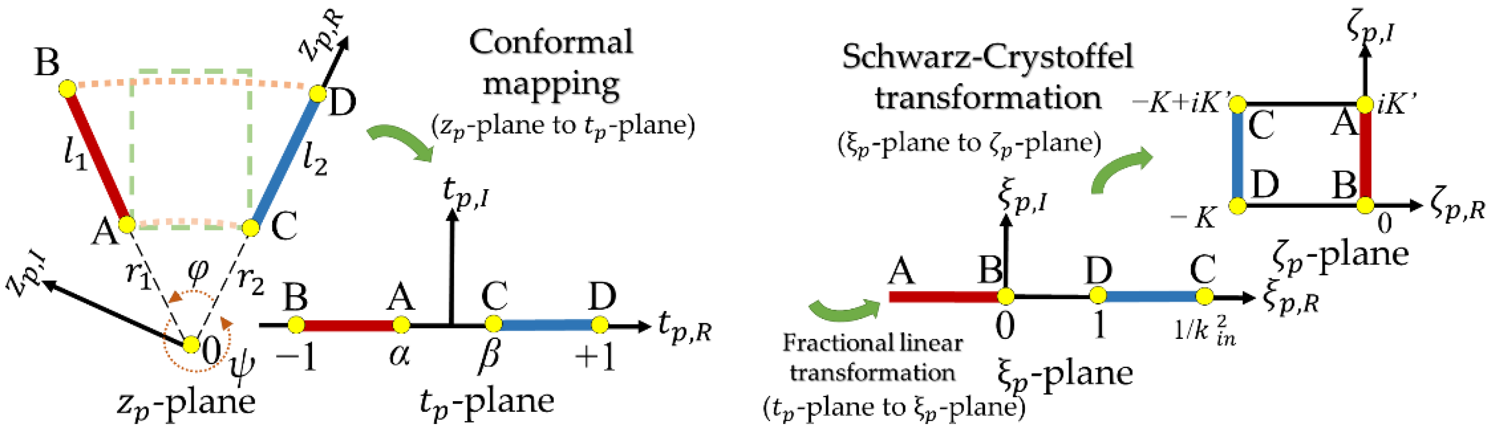
Figure 3 illustrates the conformal mapping transformation process for an inclined-plate capacitor per unit longitudinal length transforming to a parallel-plate capacitor configuration. In Table 2, three transfer equations were used to derive Equation (6) for the equivalent parallel-plate capacitor (Cin and Cout) in the ζp -plane. We know that obtaining the inclined-plate capacitance is not an easy task, so using the conformal mapping method is more straightforward because it transforms the problem into a set of simpler algebra equations.
Equation (6) indicates that Cin and Cout are from an electrostatic field enclosed by the two electrodes in the interior of angles φ and ψ. The modulus kin is related to the inside angle φ
and the complementary modulus of k′in is expressed as
Additionally, for the field region of angle ψ, we can determine kout and k′out by using the following expressions
and
We consider that the surface charge of the electrodes on the membrane is redistributed after vibration (Figure 4) and do not consider the interaction between the capacitors. By using Equations (5) and (6), the capacitive variation in the nth electrode ring and the total capacitive variation can be calculated as follows
where Cn is the n-th capacitance per unit longitudinal length, which is composed by the internal capacitance Cin,n and the external capacitance C out,n; Cs is the capacitance before vibration; and Cd is the total capacitive variation, which is the sum of the capacitive variation in electrode rings on the membrane.
Based on the voltage-constrained conversion cycle [17] and Equations (4)–(6), the energy gain per vibration cycle of the harvester is expressed as follows
where ΔC is the capacitance difference, which is the difference of peak and valley capacitance. For our harvester, the capacitance depends on the periodic deflection of the membrane um(r,t) with time, so that ΔC equals (2│Cd,max│).
3. Results and Discussion
In order to examine the effect of the inclined-plate capacitor on the circular membrane, the rotating and the non-rotating electrode structures are discussed. A comparison of the capacitive change over the normalized displacement between the rotating structure vs. the non-rotating structure is provided in Figure 5, where the capacitance of the rotating structure is calculated using Equation (6), and the capacitance of the non-rotating structure is obtained from the ideal capacitance formula. In addition, we verified seven sets of data of the rotating structure (dg/h = 0, 0.09, 0.17, 0.26, 0.34, 0.42, 0.5) by FEM, and the relative errors of capacitance between using Equation (6) and FEM are less than 2.7%. It is seen from Figure 5 that the capacitive change in the non-rotating structure is greater than that of the rotating structure, meaning that the former is able to collect more energy with the same displacement.
We assume that the subsidence of the membranous center point is δ = 0.5 R, the height of rigid electrode is h = s/0.075, the radius of the membrane is R = 1 cm, and λmt = 2π, so the deformation of the membrane in 1st–4th modes, shown in Figure 6, can be obtained from Equation (4). With Equation (5), we have the N-capacitive rings on the circular membrane, and each capacitive ring has its own inside angle φn, where n = 1 to N represents the n-th capacitive ring. According to Equations (6)–(11) and the curve of the deformed membrane, the n-th capacitance per unit longitudinal length Cn can be evaluated.
Figure 6 presents the distributions of the capacitances per unit length Cn (Cin,n + Cout,n) along the radius of the membrane in the 1st–4th modes, and the ranges for the modes are 118.0156–118.7415 pF/m in the 1st mode, 118.0884–118.3985 pF/m in the 2nd mode, 118.1989–118.2679 pF/m in the 3rd mode, and 118.2186–118.2679 pF/m in the 4th mode. It is clear that the range in the lower mode is wide, which reveals that the first mode is beneficial for energy harvesting. The result also shows that the larger angle between electrodes leads to the larger absolute capacitive variation. In other words, the minimum absolute capacitive variations are shown at the angles, which are approximately zero (φ = 0°). The 0° angle occurs at the corresponding inflection points in the deformation curves, at which the absolute capacitive variation is zero. Specifically, one point is observed in the 1st mode (r = 0.76, Figure 6a), two points are observed in the 2nd mode (r = 0.33 and 0.97, Figure 6b), three points are observed in the 3rd mode (r = 0.21, 0.61, and 0.96, Figure 6c) and four points are observed in the 4th mode (r = 0.14, 0.45, 0.73 and 0.93, Figure 6d). We note that the change in the capacitance is correlated to the angle between electrodes such that one can observe the capacitive variation could be positive or negative along the radius of the membrane (the relationship between capacitive variation and angle is shown in Figure 6e). Despite the existence of negative values that affect the efficiency of conversion of mechanical vibration to electrical energy, overall, the influence of the positive values still overrides that of the negative ones. It should also be pointed out that the negative values can only be obtained from a theoretical analysis, which thus indicates the strength of our approach.
In terms of the size of the capacitive gap, we compare the capacitance of the rings with three types of gaps (s = 1, 10, and 100 μm, and the relative rings are 9999, 999, and 99 circles) for the 1st mode. Figure 7a illustrates that the ring with s = 100 μm exhibits the highest capacitance per unit longitudinal length due to a larger φn. In addition, Figure 7b displays the capacitive variation in the three types of electrical rings around the circle center along the radius, which are obtained from Equation (11). The capacitive variations of the electrical ring are −13.580–8.691, −1.396–0.877, and −0.140–0.088 fF for the membranes with gaps of 100, 10, and 1 μm, respectively. However, in the first mode, the totals of capacitive variations Cd for the three gaps (s = 1, 10, and 100 μm) are similar, and their values are indicated in Figure 7b.
Concerning the modal shape, we obtain the capacitive variation in the electrical rings along the radius of the membrane in 1st–4th mode with s = 100 μm (see Figure 8a). It is found that the amplitude of the Cd,n decreases with increasing modes. We also notice that the Cd,n can have positive and negative values at any given moment during vibration, as shown in Figure 8a. In addition, with Equation (12), the energy output per cycle for the three types of energy harvester can be calculated. Figure 8b shows the results that the energy outputs for the three types of rings of s = 100, 10, 1 μm are similar, and the energy output greatly decreases in the 3rd and 4th modes due to smaller deformation. We see that all of the energy per cycle falls within the range of 0.052–25.10 nJ, which indicates that the energy output is independent of the gap size. As stated above, under each mode, the absolute values of capacitive variation │Cd,n│, and the angle change φn are positively correlated. Since the angle profiles φ(r) for different gap sizes are the same, which indicates the sums of φn for different gap sizes are equal, we can find that the sum of Cd,n, i.e., Cd, for different gap sizes will be maintained. This accounts for the evaluation in Figure 8b that the energy output of the three devices is numerically close to each other. In short, gap sizes do not affect the energy output in our device.
In order to raise the energy output of the harvester in the first-mode deformation, we consider only the IRE coating between r = 0–0.76 of the membrane (see Figure 7b). Thus all of the capacitive variations are positive, and the calculated energy output is raised to 38.68 nJ per cycle. Assuming the vibration is 30 Hz controlled by adjusting Tp, a power density of 0.37 μW /cm2 would be achieved for this IRE design on the circular membrane. Table 3 compares the parameters used in our study to assess power densities (IRE) with those used in previous studies (IDE).
In Table 3, the power density of the variable-capacitance harvester is associated with the values of the gap, the voltage, and the frequency. However, the power density of the IRE design is generally smaller than that of the IDE designs. This can be explained by Figure 5, showing that, compared with the non-rotating electrodes, the rotating electrodes give rise to a smaller capacitance difference per vibration cycle under the same normalized displacement. Nevertheless, the IRE device is featured in large gap distance (millimeter-scale), and it can be manufactured by a printed circuit board (PCB) technology at a low price [22]. Comparatively, the bulk of IDE designs is operated by applying the high-frequency vibration source on a small-scale device, which, however, has a higher resonance frequency due to its size [23]. Since the majority of the natural vibration sources are low-frequency within the range of 30–200 Hz [24], our membranous device, which controls the frequency of the first mode at 30 Hz by adjusting the tension force of the membrane and could be triggered with wind, water flow, and sound wave easily, is a more feasible design.
4. Conclusions
A mathematical model combining variable capacitance and vibrated circular membrane was proposed to analyze the energy output of capacitive rings on circular membranes in vibration 1st–4th modes. We obtain the capacitive variation in inclined-plate capacitors by algebraic calculation. This study also shows a positive correlation between the energy output and electrodes′ angle. By way of illustration, the first mode performs the best energy output, which is 1.44 times that of the second mode, 33.13 times that of the third mode, and 476.53 times that of the fourth mode. Most non-rotating electrode design models need to minimize the gap size to improve energy output [25]; fortunately, in our design, it is proven that the gap size between the rotating electrodes is independent of the energy output. Therefore, the IRE mechanism has a high potential to be applied in the millimeter-scale and has the advantage of being low-cost in manufacturing.
Author Contributions
Conceptualization, H.-J.S. and K.-C.C.; methodology, H.-J.S.; software, H.-J.S.; writing—original draft preparation, H.-J.S.; writing—review and editing, H.-J.S. and K.-C.C. All authors have read and agreed to the published version of the manuscript.
Funding
This research received no external funding.
Acknowledgments
This article was subsidized by the Ministry of Science and Technology and National Taiwan University (NTU), Taiwan.
Conflicts of Interest
The authors declare no conflict of interest.
References
- Krupenkin, T.; Taylor, J.A. Reverse electrowetting as a new approach to high-power energy harvesting. Nat. Commun. 2011, 2, 448. [Google Scholar] [CrossRef] [PubMed] [Green Version]
- Hsu, T.H.; Manakasettharn, S.; Taylor, J.A.; Krupenkin, T. Bubbler: A novel ultra-high power density energy harvesting method based on reverse electrowetting. Sci. Rep. 2015, 5, 16537. [Google Scholar] [CrossRef] [PubMed] [Green Version]
- Tashiro, R.; Kabei, N.; Katayama, K.; Ishizuka, Y.; Tsuboi, F.; Tsuchiya, K. Development of an electrostatic generator that harnesses the motion of a living body (use of a resonant phenomenon). Jsme Int. J. Ser. C-Mech. Syst. Mach. Elem. Manuf. 2000, 43, 916–922. [Google Scholar] [CrossRef] [Green Version]
- Suzuki, Y.; Miki, D.; Edamoto, M.; Honzumi, M. A MEMS electret generator with electrostatic levitation for vibration-driven energy-harvesting applications. J. Micromech. Microeng. 2010, 20, 104002. [Google Scholar] [CrossRef]
- Wei, C.F.; Jing, X.J. A comprehensive review on vibration energy harvesting: Modelling and realization. Renew. Sustain. Energy Rev. 2017, 74, 1–18. [Google Scholar] [CrossRef]
- Naruse, Y.; Matsubara, N.; Mabuchi, K.; Izumi, M.; Suzuki, S. Electrostatic micro power generation from low-frequency vibration such as human motion. J. Micromech. Microeng. 2009, 19, 094002. [Google Scholar] [CrossRef]
- Sterken, T.; Baert, K.; Puers, R.; Borghs, G. Power Extraction from Ambient Vibration. In Proceedings of the 3rd Workshop on Semiconductor Sensors and Actuators, Veldhoven, The Netherlands, 29 November 2002; pp. 680–683. [Google Scholar]
- Wang, F.; Hansen, O. Electrostatic energy harvesting device with out-of-the-plane gap closing scheme. Sens. Actuators A Phys. 2014, 211, 131–137. [Google Scholar] [CrossRef]
- Oberlander, J.; Jildeh, Z.B.; Kirchner, P.; Wendeler, L.; Bromm, A.; Iken, H.; Wagner, P.; Keusgen, M.; Schoning, M.J. Study of interdigitated electrode arrays using experiments and finite element models for the evaluation of sterilization processes. Sensors 2015, 15, 26115–26127. [Google Scholar] [CrossRef] [PubMed] [Green Version]
- Hart, C.; Rajaraman, S. Low-power, multimodal laser micromachining of materials for applications in sub-5 microm shadow masks and sub-10 microm interdigitated electrodes (IDEs) fabrication. Micromachines 2020, 11, 178. [Google Scholar] [CrossRef] [PubMed] [Green Version]
- Bryant, R.G.; Effinger, R.T.; Aranda, I.; Copeland, B.M.; Covington, E.W.; Hogge, J.M. Radial field piezoelectric diaphragms. J. Intell. Mater. Syst. Struct. 2004, 15, 527–538. [Google Scholar] [CrossRef] [Green Version]
- Zhang, X.; Shan, X.; Shen, Z.; Xie, T.; Miao, J. A new self-powered sensor using the radial field piezoelectric diaphragm in d33 mode for detecting underwater disturbances. Sensors 2019, 19, 962. [Google Scholar] [CrossRef] [Green Version]
- Hsiung, L.C.; Yang, C.H.; Chiu, C.L.; Chen, C.L.; Wang, Y.; Lee, H.; Cheng, J.Y.; Ho, M.C.; Wo, A.M. A planar interdigitated ring electrode array via dielectrophoresis for uniform patterning of cells. Biosens. Bioelectron. 2008, 24, 875–881. [Google Scholar] [CrossRef] [PubMed]
- Hsieh, K.M.; Lan, K.C.; Hu, W.L.; Chen, M.K.; Jang, L.S.; Wang, M.H. Glycated hemoglobin (HbA1c) affinity biosensors with ring-shaped interdigital electrodes on impedance measurement. Biosens. Bioelectron. 2013, 49, 450–456. [Google Scholar] [CrossRef] [PubMed]
- Kreyszig, E. Laplacian in polar coordinates circular membrane fourier–bessel series. In Advanced Engineering Mathematics, 10th ed.; Laurie Rosatone: Jefferson City, MO, USA, 2017; pp. 585–590. [Google Scholar]
- Xiang, Y.M. Further study on electrostatic capacitance of an inclined plate capacitor. J. Electrostat 2008, 66, 366–368. [Google Scholar] [CrossRef]
- Torres, E.O.; Rincón-Mora, G.A. Electrostatic Energy Harvester and Li-Ion Charger Circuit for Micro-Scale Applications. In Proceedings of the 49th IEEE International Midwest Symposium on Circuits and Systems, San Juan, PR, USA, 6–9 August 2006; pp. 65–69. [Google Scholar] [CrossRef]
- Tsutsumino, T.; Suzuki, Y.; Kasagi, N.; Sakane, Y. Seismic Power Generator Using High-Performance Polymer Electret. In Proceedings of the 19th IEEE International Conference on Micro Electro Mechanical Systems: MEMS 2006, Istanbul, Turkey, 22–26 January 2006; pp. 98–101. [Google Scholar]
- Roundy, S.; Wright, P.K.; Rabaey, J.M. Energy Scavenging for Wireless Sensor Networks: With Special Focus on Vibrations; Kluwer Academic Publishers: Norwell, MA, USA, 2004. [Google Scholar] [CrossRef]
- Basset, P.; Galayko, D.; Paracha, A.M.; Marty, F.; Dudka, A.; Bourouina, T. A batch-fabricated and electret-free silicon electrostatic vibration energy harvester. J. Micromech. Microeng. 2009, 19, 115025. [Google Scholar] [CrossRef] [Green Version]
- Hoffmann, D.; Folkmer, B.; Manoli, Y. Fabrication, characterization and modelling of electrostatic micro-generators. J. Micromech. Microeng. 2009, 19, 094001. [Google Scholar] [CrossRef]
- Yang, B. Hybrid energy harvester based on piezoelectric and electromagnetic mechanisms. J. Micro/Nanolithogr. MEMS MOEMS 2010, 9, 023002. [Google Scholar] [CrossRef]
- Xu, R.; Akay, H.; Kim, S.G. Buckled MEMS beams for energy harvesting from low frequency vibrations. Research 2019, 2019, 1087946. [Google Scholar] [CrossRef] [Green Version]
- Huang, M.; Hou, C.; Li, Y.; Liu, H.; Wang, F.; Chen, T.; Yang, Z.; Tang, G.; Sun, L. A low-frequency MEMS piezoelectric energy harvesting system based on frequency up-conversion mechanism. Micromachines 2019, 10, 639. [Google Scholar] [CrossRef] [PubMed] [Green Version]
- Boisseau, S.; Despesse, G.; Seddik, B.A. Electrostatic conversion for vibration energy harvesting. In Small-Scale Energy Harvesting; Lallart, M., Ed.; INTECH: Lexington, KY, USA, 2012. [Google Scholar] [CrossRef] [Green Version]
Figure 1.
Top and section views of the circular membrane.

Figure 2.
Schematic of the circular membrane energy harvester: (a) nomenclature of the circular membrane of variable capacitance C(t) and the equivalent circuit diagram; (b) mechanism of the circular membrane energy harvester.
Figure 2.
Schematic of the circular membrane energy harvester: (a) nomenclature of the circular membrane of variable capacitance C(t) and the equivalent circuit diagram; (b) mechanism of the circular membrane energy harvester.

Figure 3.
Conformal mapping transformation process for two electrodes per unit longitudinal length. First, the cross-section of the inclined-plate capacitor of the ring on the membrane (zp-plane) is mapped onto the upper half plane (tp-plane). Second, the tp-plane is mapped onto the ξp-plane through fractional linear transformation. Third, the ξp-plane is mapped onto the ζp -plane through the Schwarz-Crystoffel transformation.

Figure 4.
Capacitance on the circular membrane before and after vibration.

Figure 5.
Capacitance per unit length versus normalized displacement for the rotating and non-rotating electrodes.
Figure 5.
Capacitance per unit length versus normalized displacement for the rotating and non-rotating electrodes.

Figure 6.
The membranous deformation um (blue), the n-th angle φn (pink) and capacitance (green) per unit longitudinal length Cn (Cin + Cout) along the radius of the membrane in various modes: (a) 1st mode, (b) 2nd mode, (c) 3rd mode, and (d) 4th mode. Cs = 118.233 pF/m means the capacitance before vibration. (e) The plot of (Cn − Cs) vs. angle of electrode.

Figure 7.
(a) The capacitance per unit longitudinal length Cn (Cin + Cout) and (b) the capacitive variation in the electrical rings (Cd,n) along radius of membrane for the 1st mode at the gaps s = 100, 10, and 1 μm.
Figure 7.
(a) The capacitance per unit longitudinal length Cn (Cin + Cout) and (b) the capacitive variation in the electrical rings (Cd,n) along radius of membrane for the 1st mode at the gaps s = 100, 10, and 1 μm.

Figure 8.
(a) The capacitive variation in the rings of s = 100 μm along the radius of the membrane (Cd,n) and (b) energy output per cycle for the rings of s = 100, 10, and 1 μm when Vbias = 300 V for energy harvesters in the 1st–4th modes.
Figure 8.
(a) The capacitive variation in the rings of s = 100 μm along the radius of the membrane (Cd,n) and (b) energy output per cycle for the rings of s = 100, 10, and 1 μm when Vbias = 300 V for energy harvesters in the 1st–4th modes.


Table 1.
Values of αm and the first-order Bessel functions of the first kind for modes 1–4 [15].
Table 1.
Values of αm and the first-order Bessel functions of the first kind for modes 1–4 [15].
| m | αm | J1(αm) |
|---|---|---|
| 1 | 2.40483 | 0.51915 |
| 2 | 5.52008 | −0.34026 |
| 3 | 8.65373 | 0.27145 |
| 4 | 11.79153 | −0.23246 |
Table 2.
The successive coordinate transformations of the inclined plate.
| Plane | Used Transfer Equations | Point-A | Point-B | Point-C | Point-D |
|---|---|---|---|---|---|
| zp-plane | r1eiφ | (r1 + l1)eiφ | r2 | r2 + l2 | |
| tp-plane | tp = Mzpπ/φ + M0 | (α, 0) | (−1, 0) | (β, 0) | (1, 0) |
| ξp-plane | ξp = 0.5 (1 − α)(1 + tp)/(tp − α) | (−∞, 0) | (0, 0) | (1/k2, 0) | (1, 0) |
| ζp-plane | Schwarz-Crystoffel | (0, iK′) | (0, 0) | (−K, iK′) | (−K, 0) |
Table 3.
Parameters of various electrostatic VEHs.
| Author | Ref | Output Power (μW) | Device Area (cm2) | Power Density (μW/cm2) | Frequency (Hz) | Gap (μm) | Voltage (V) |
|---|---|---|---|---|---|---|---|
| This study 1 | - | 1.16 | π | 0.37 | 30 | 100 | 300 |
| Tsutsumino 2 | [18] | 38 | 3.00 | 12.67 | 20 | 15 | 950 |
| Suzuki 2 | [4] | 1 | 3.05 | 0.33 | 63 | 50 | 180 |
| Roundy 2 | [19] | 11 | 1.00 | 11.00 | 100 | 0.25 | 10 |
| Basset 2 | [20] | 0.061 | 0.66 | 0.92 | 250 | 1.7 | 8 |
| Hoffmann 2 | [21] | 3.5 | 0.30 | 11.67 | 1300–1500 | 2.5 | 50 |
1 Using the IRE design (pure model). 2 Using the IDE design (experimental).
Publisher′s Note: MDPI stays neutral with regard to jurisdictional claims in published maps and institutional affiliations. |
© 2022 by the authors. Licensee MDPI, Basel, Switzerland. This article is an open access article distributed under the terms and conditions of the Creative Commons Attribution (CC BY) license (https://creativecommons.org/licenses/by/4.0/).
Share and Cite
MDPI and ACS Style
Shih, H.-J.; Chen, K.-C. An Analytical Energy Harvester Model for Interdigitated Ring Electrode on Circular Elastic Membrane. Micromachines 2022, 13, 133. https://0-doi-org.brum.beds.ac.uk/10.3390/mi13010133
AMA Style
Shih H-J, Chen K-C. An Analytical Energy Harvester Model for Interdigitated Ring Electrode on Circular Elastic Membrane. Micromachines. 2022; 13(1):133. https://0-doi-org.brum.beds.ac.uk/10.3390/mi13010133
Chicago/Turabian StyleShih, Hua-Ju, and Kuo-Ching Chen. 2022. "An Analytical Energy Harvester Model for Interdigitated Ring Electrode on Circular Elastic Membrane" Micromachines 13, no. 1: 133. https://0-doi-org.brum.beds.ac.uk/10.3390/mi13010133
Note that from the first issue of 2016, this journal uses article numbers instead of page numbers. See further details here.