
Development of Tiny Vane-Type Magnetorheological Brake Considering Quality Function Deployment
 , , and
Abstract
:1. Introduction
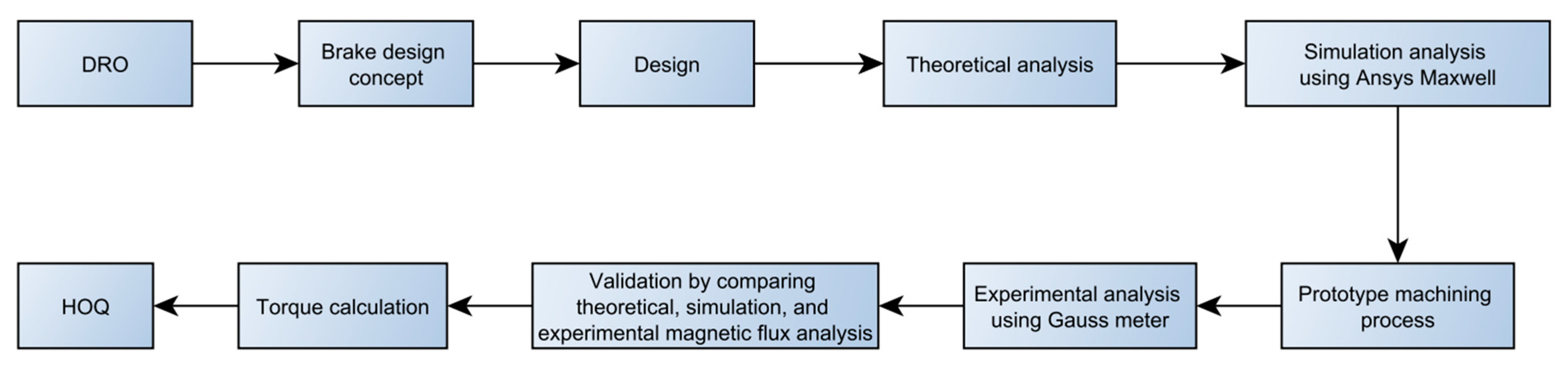
2. Materials and Methods
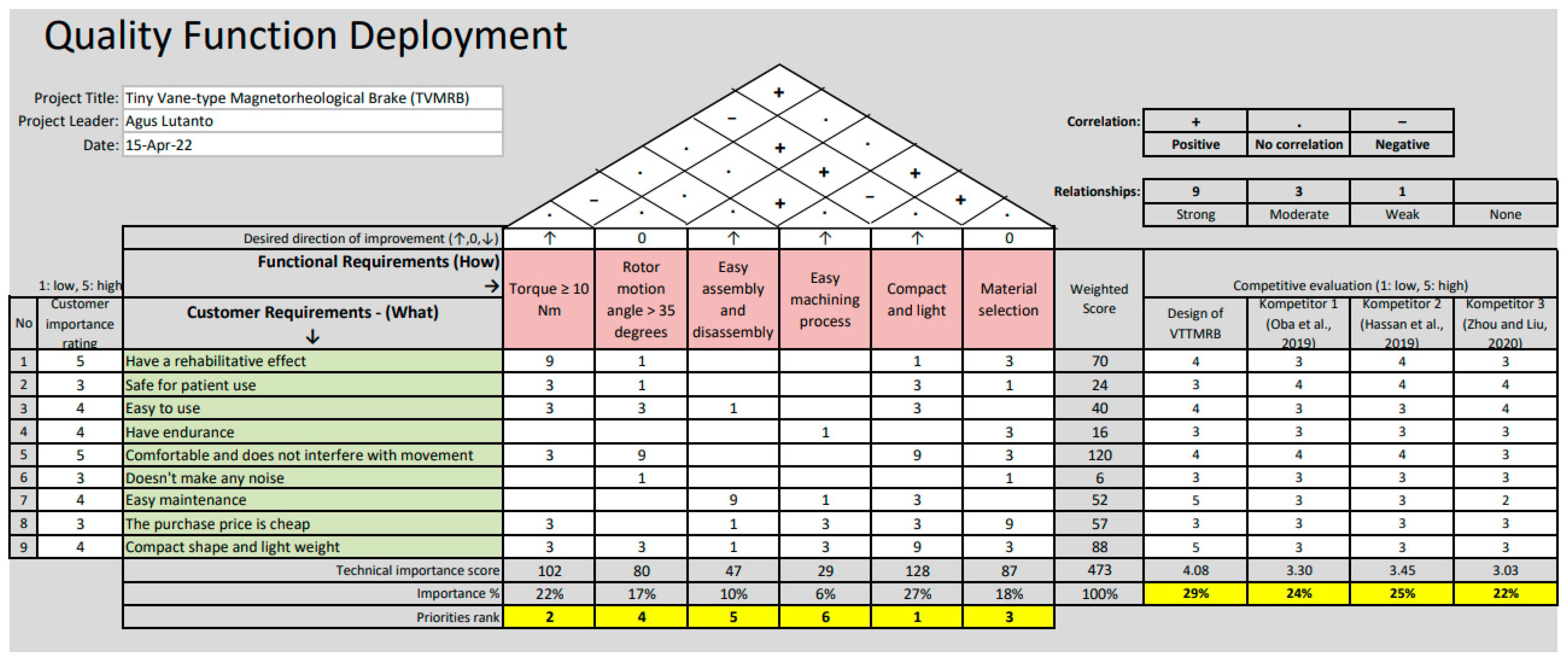
2.1. Quality Function Deployment Concept
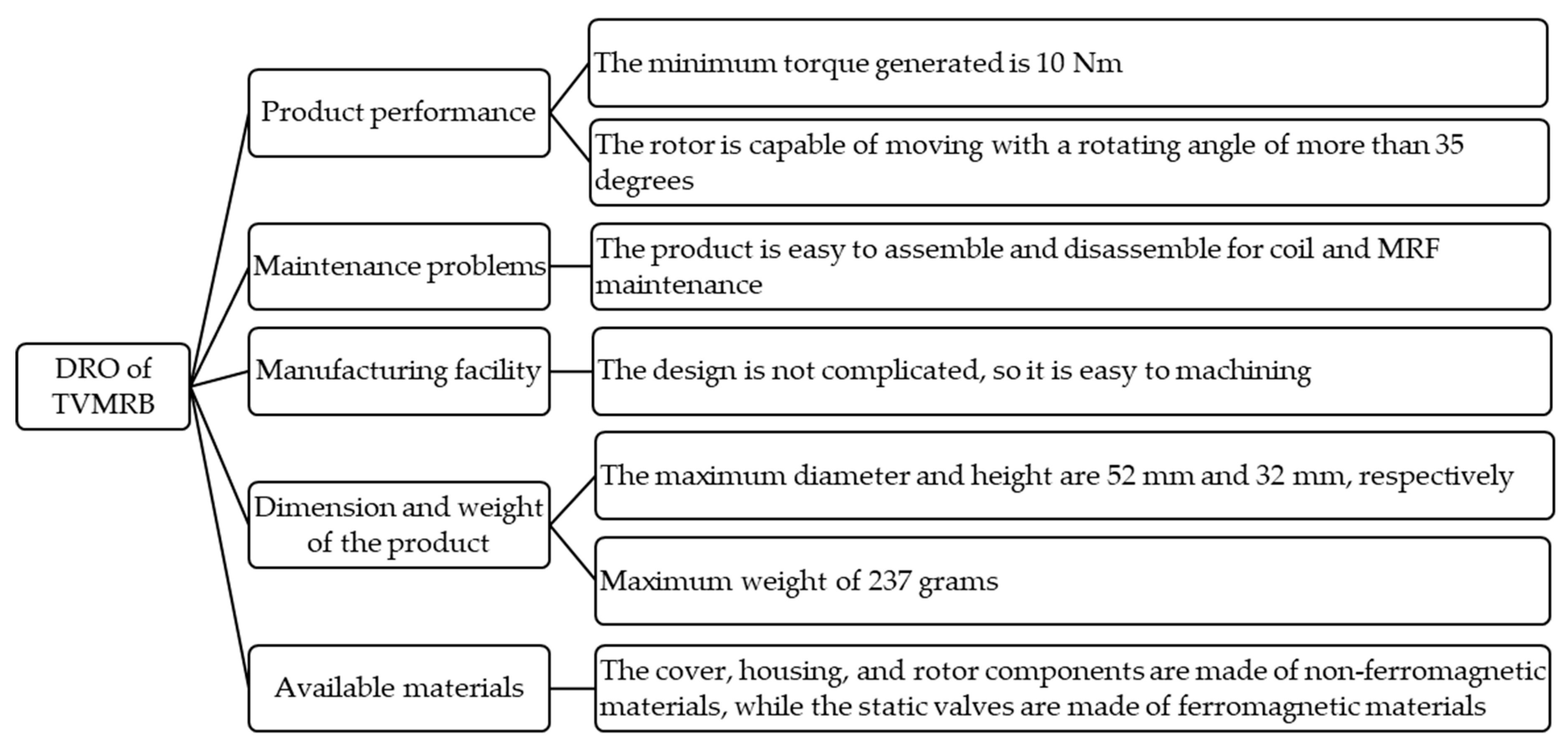
2.2. Design Requirement and Objective
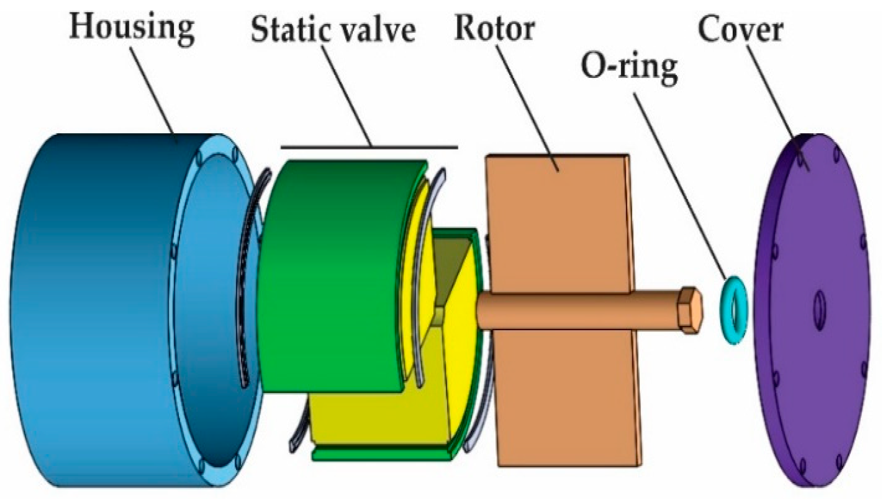
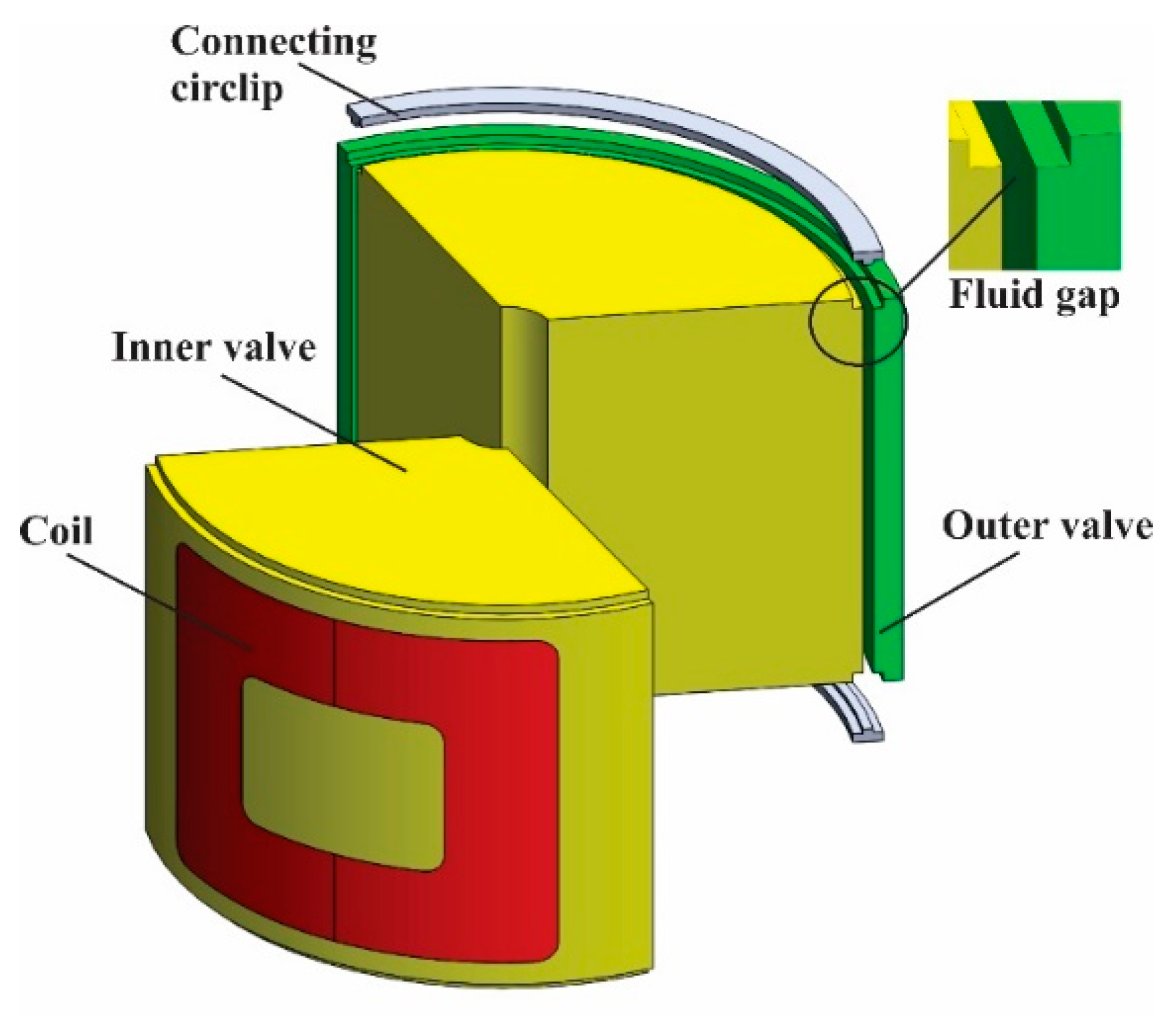
2.3. Structure Design and Materials
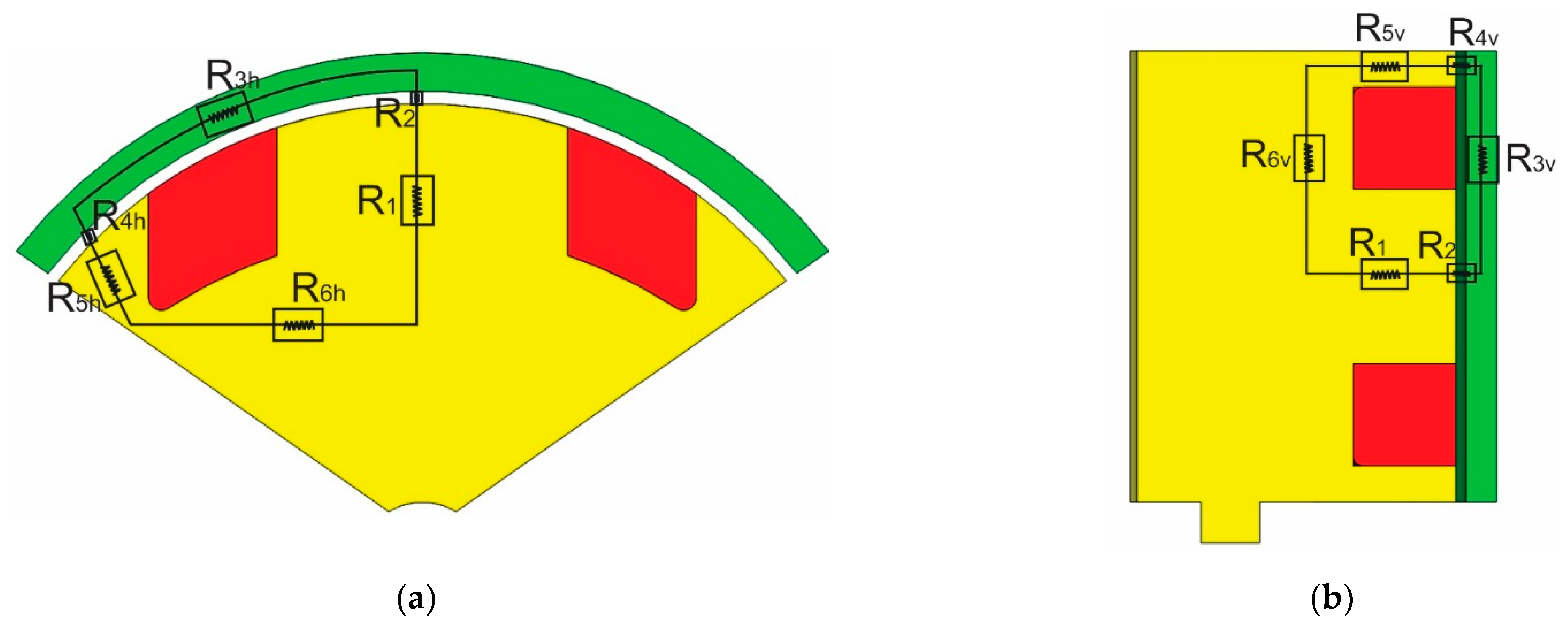
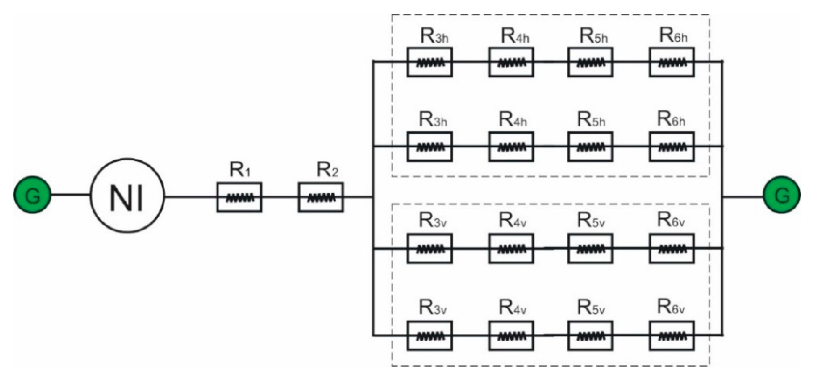
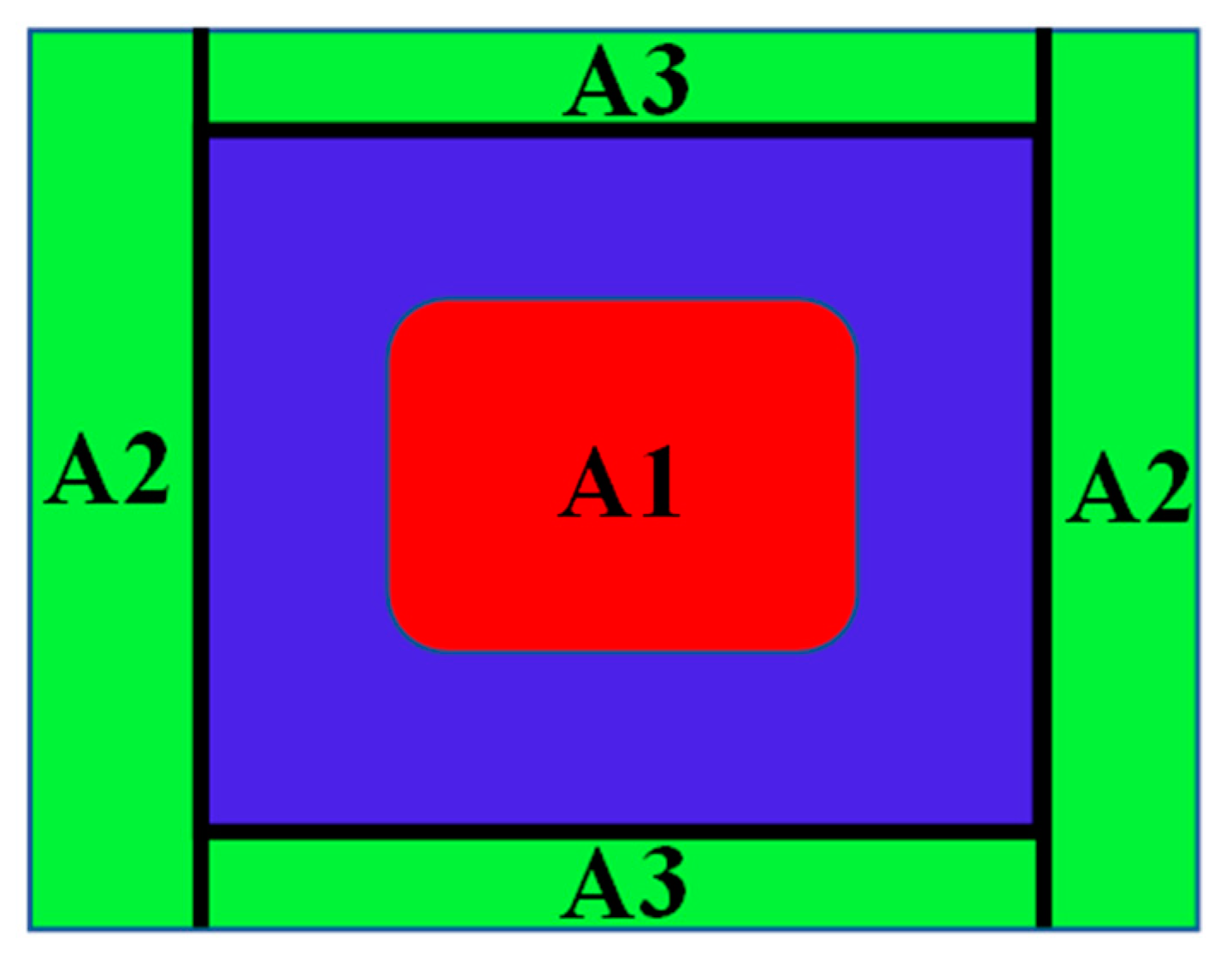
2.4. Electromagnetic Circuit Model
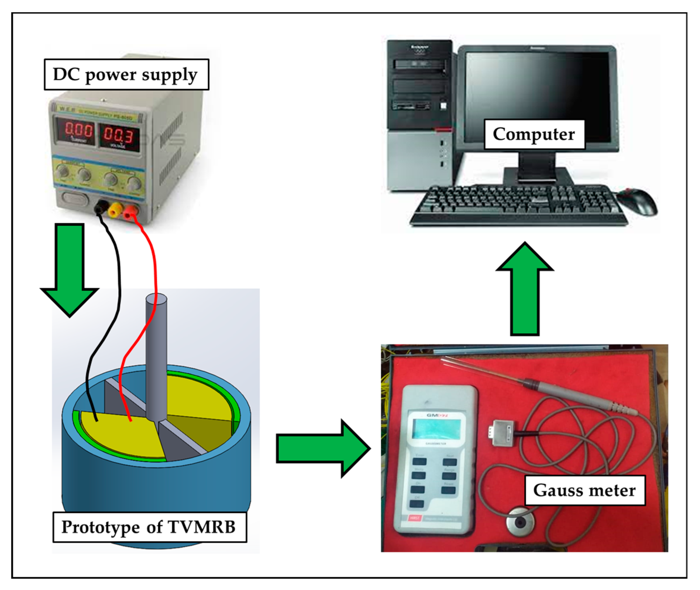
2.5. Testing Scheme
3. Results and Discussion
3.1. Torque Characteristics
3.2. House of Quality (HOQ)
4. Conclusions
Author Contributions
Funding
Institutional Review Board Statement
Informed Consent Statement
Data Availability Statement
Acknowledgments
Conflicts of Interest
References
- Nguyen, T.; Munguia, V.; Calderon, J. Prosthetic Leg Powered by MR Brake and SMA Wires. In Proceedings of the Active and Passive Smart Structures and Integrated Systems 2014, San Diego, CA, USA, 1 April 2014; Liao, W.-H., Ed.; Volume 9057, p. 90572S. [Google Scholar]
- Hassan, M.; Yagi, K.; Kadone, H.; Ueno, T.; Mochiyama, H.; Suzuki, K. Optimized Design of a Variable Viscosity Link for Robotic AFO. In Proceedings of the 2019 41st Annual International Conference of the IEEE Engineering in Medicine and Biology Society (EMBC), Berlin, Germany, 23–27 July 2019; pp. 6220–6223. [Google Scholar] [CrossRef]
- Zhou, Y.; Liu, L. A Multifunctional Ankle Foot Orthosis Utilizing a Magnetorheological Actuator. IOP Conf. Series Mater. Sci. Eng. 2020, 813, 012001. [Google Scholar] [CrossRef]
- Ubaidillah; Wibowo, A.; Adiputra, D.; Tjahjana, D.D.D.P.; Rahman, M.A.A.; Mazlan, S.A. Performance Prediction of Serpentine Type Compact Magnetorheological Brake Prototype. In AIP Conference Proceedings; AIP Publishing LLC: New York, NY, USA, 2017; Volume 1788, p. 030032. [Google Scholar]
- Adiputra, D.; Nazmi, N.; Bahiuddin, I.; Ubaidillah, U.; Imaduddin, F.; Rahman, M.A.A.; Mazlan, S.A.; Zamzuri, H. A Review on the Control of the Mechanical Properties of Ankle Foot Orthosis for Gait Assistance. Actuators 2019, 8, 10. [Google Scholar] [CrossRef] [Green Version]
- Imaduddin, F.; Mazlan, S.A.; Zamzuri, H. A design and modelling review of rotary magnetorheological damper. Mater. Des. 2013, 51, 575–591. [Google Scholar] [CrossRef]
- Kumbhar, B.K.; Patil, S.R.; Sawant, S.M. Synthesis and characterization of magneto-rheological (MR) fluids for MR brake application. Eng. Sci. Technol. Int. J. 2015, 18, 432–438. [Google Scholar] [CrossRef] [Green Version]
- Hidayatullah, F.H.; Ubaidillah, U.; Purnomo, E.D.; Tjahjana, D.D.D.P.; Wiranto, I.B. Design and simulation of a combined serpentine t-shape magnetorheological brake. Indones. J. Electr. Eng. Comput. Sci. 2019, 13, 1221–1227. [Google Scholar] [CrossRef]
- Song, W.; Wang, S.; Choi, S.-B.; Wang, N.; Xiu, S. Thermal and tribological characteristics of a disc-type magnetorheological brake operated by the shear mode. J. Intell. Mater. Syst. Struct. 2019, 30, 722–733. [Google Scholar] [CrossRef]
- Oba, T.; Kadone, H.; Hassan, M.; Suzuki, K. Robotic Ankle–Foot Orthosis With a Variable Viscosity Link Using MR Fluid. IEEE ASME Trans. Mechatron. 2019, 24, 495–504. [Google Scholar] [CrossRef]
- Satria, R.R.; Ubaidillah; Imaduddin, F. Analytical Approach of a Pure Flow Mode Serpentine Path Rotary Magnetorheological Damper. Actuators 2020, 9, 56. [Google Scholar] [CrossRef]
- Saini, R.; Chandramohan, S.; Sujatha, S.; Kumar, H. Design of bypass rotary vane magnetorheological damper for prosthetic knee application. J. Intell. Mater. Syst. Struct. 2020, 32, 931–942. [Google Scholar] [CrossRef]
- Farjoud, A.; Craft, M.; Burke, W.; Ahmadian, M. Experimental Investigation of MR Squeeze Mounts. J. Intell. Mater. Syst. Struct. 2011, 22, 1645–1652. [Google Scholar] [CrossRef]
- Chen, P.; Bai, X.-X.; Qian, L.-J.; Choi, S.-B. A magneto-rheological fluid mount featuring squeeze mode: Analysis and testing. Smart Mater. Struct. 2016, 25, 055002. [Google Scholar] [CrossRef]
- Yi, A.; Zahedi, A.; Wang, Y.; Tan, U.-X.; Zhang, D. A Novel Exoskeleton System Based on Magnetorheological Fluid for Tremor Suppression of Wrist Joints. In Proceedings of the 2019 IEEE 16th International Conference on Rehabilitation Robotics (ICORR), Toronto, ON, Canada, 24–28 June 2019; pp. 1115–1120. [Google Scholar] [CrossRef]
- Nam, T.H.; Ahn, K.K. A new structure of a magnetorheological brake with the waveform boundary of a rotary disk. Smart Mater. Struct. 2009, 18, 115029. [Google Scholar] [CrossRef]
- Chen, S.; Yang, J. Probing Slip Differential Heat of Magnetorheological Fluids Subjected to Shear Mode Operation and Its Effect on the Structure. Materials 2019, 12, 1860. [Google Scholar] [CrossRef] [PubMed] [Green Version]
- Li, Y.D.; Hsiao-Wecksler, E.T. Gait Mode Recognition and Control for a Portable-Powered Ankle-Foot Orthosis. In Proceedings of the 2013 IEEE 13th International Conference on Rehabilitation Robotics (ICORR), Seattle, WA, USA, 24–26 June 2013; pp. 1–8. [Google Scholar]
- Kim, S.J.; Na, Y.; Lee, D.Y.; Chang, H.; Kim, J. Pneumatic AFO Powered by a Miniature Custom Compressor for Drop Foot Correction. IEEE Trans. Neural Syst. Rehabil. Eng. 2020, 28, 1781–1789. [Google Scholar] [CrossRef]
- Neubauer, B.; Durfee, W. Preliminary Design and Engineering Evaluation of a Hydraulic Ankle–Foot Orthosis. J. Med. Devices 2016, 10, 041002. [Google Scholar] [CrossRef]
- Furusho, J.; Kikuchi, T.; Tokuda, M.; Kakehashi, T.; Ikeda, K.; Morimoto, S.; Hashimoto, Y.; Tomiyama, H.; Nakagawa, A.; Akazawa, Y. Development of Shear Type Compact MR Brake for the Intelligent Ankle-Foot Orthosis and Its Control; Research and Development in NEDO for Practical Application of Human Support Robot. In Proceedings of the 2007 IEEE 10th International Conference on Rehabilitation Robotics, Noordwijk, The Netherlands, 13–15 June 2007; pp. 89–94. [Google Scholar] [CrossRef]
- Kikuchi, T.; Tanida, S.; Otsuki, K.; Yasuda, T.; Furusho, J. Development of third-generation intelligently Controllable ankle-foot orthosis with compact MR fluid brake. In Proceedings of the 2010 IEEE International Conference on Robotics and Automation, Anchorage, AK, USA, 3–7 May 2010; pp. 2209–2214. [Google Scholar] [CrossRef]
- Kim, J.-H.; Oh, J.-H. Development of an above knee prosthesis using MR damper and leg simulator. In Proceedings of the 2001 ICRA. IEEE International Conference on Robotics and Automation, Seoul, Republic of Korea, 21–26 May 2001; pp. 3686–3691. [Google Scholar] [CrossRef]
- Giorgetti, A.; Baldanzini, N.; Biasiotto, M.; Citti, P. Design and testing of a MRF rotational damper for vehicle applications. Smart Mater. Struct. 2010, 19, 065006. [Google Scholar] [CrossRef]
- Imaduddin, F.; Mazlan, S.A.; Zamzuri, H.; Rahman, M.A.A. Bypass Rotary Magnetorheological Damper for Automotive Applications. Appl. Mech. Mater. 2014, 663, 685–689. [Google Scholar] [CrossRef]
- Wei, M.; Rui, X.; Zhu, W.; Yang, F.; Gu, L.; Zhu, H. Design, modelling and testing of a novel high-torque magnetorheological damper. Smart Mater. Struct. 2020, 29, 025024. [Google Scholar] [CrossRef]
- Zhang, P.; Kamezaki, M.; Otsuki, K.; He, S.; He, Z.; Dominguez, G.A.; Sugano, S. Development and Evaluation of a Backdrivable Vane-Type Rotary Actuator Using Magnetorheological Fluids. IEEE ASME Trans. Mechatron. 2022, 27, 4863–4873. [Google Scholar] [CrossRef]
- Rahman, M.; Ong, Z.C.; Julai, S.; Ferdaus, M.; Ahamed, R. A review of advances in magnetorheological dampers: Their design optimization and applications. J. Zhejiang Univ. A 2017, 18, 991–1010. [Google Scholar] [CrossRef]
- Govers, C. What and how about quality function deployment (QFD). Int. J. Prod. Econ. 1996, 46–47, 575–585. [Google Scholar] [CrossRef]
- Hernández-Rangel, F.; Saavedra-Leos, M.; Morales-Morales, J.; Bautista-Santos, H.; Reyes-Herrera, V.; Rodríguez-Lelis, J.; Cruz-Alcantar, P. Continuous Improvement Process in the Development of a Low-Cost Rotational Rheometer. Processes 2020, 8, 935. [Google Scholar] [CrossRef]
- Cazacu, C.M.R.; Doroftei, I. Structural and Kinematic Aspects of a New Ankle Rehabilitation Device. Appl. Mech. Mater. 2014, 658, 507–512. [Google Scholar] [CrossRef]
- Gholami, M.; Napier, C.; Menon, C. Estimating Lower Extremity Running Gait Kinematics with a Single Accelerometer: A Deep Learning Approach. Sensors 2020, 20, 2939. [Google Scholar] [CrossRef]
- Carmona, I.C.; Kumbhare, D.; Baron, M.S.; Hadimani, R.L. Quintuple AISI 1010 carbon steel core coil for highly focused transcranial magnetic stimulation in small animals. AIP Adv. 2021, 11, 025210. [Google Scholar] [CrossRef]
- Lord, C. MRF-132DG Magneto-Rheological Fluid. Lord Prod. Sel. Guid. Lord Magnetorheol. Fluids 2011, 54, 11. [Google Scholar]
- Imaduddin, F.; Mazlan, S.A.; Zamzuri, H.; Yazid, I.I.M. Design and performance analysis of a compact magnetorheological valve with multiple annular and radial gaps. J. Intell. Mater. Syst. Struct. 2015, 26, 1038–1049. [Google Scholar] [CrossRef]
- Wu, J.; Hu, H.; Li, Q.; Wang, S.; Liang, J. Simulation and experimental investigation of a multi-pole multi-layer magnetorheological brake with superimposed magnetic fields. Mechatronics 2020, 65, 102314. [Google Scholar] [CrossRef]
- Herrault, F.; Yorish, S.; Crittenden, T.; Allen, M.G. Microfabricated, Ultra-Dense, Three-Dimensional Metal Coils. In Proceedings of the TRANSDUCERS 2009–2009 International Solid-State Sensors, Actuators and Microsystems Conference, Denver, CO, USA, 21–25 June 2009; pp. 1718–1721. [Google Scholar]
- Arifin, Z.; Prasetyo, S.D.; Ubaidillah, U.; Suyitno, S.; Tjahjana, D.D.P.; Juwana, W.E.; Rachmanto, R.A.; Prabowo, A.R.; Apribowo, C.H.B. Helmet Stick Design for BC3 Paramlympic Bocia Games. Math. Model. Eng. Probl. 2022, 9, 637–644. [Google Scholar] [CrossRef]


| Properties | Value/Limits |
|---|---|
| Codes of MR fluids | MRF-132 DG |
| Based fluid | Hydrocarbon |
| Appearance | Dark gray liquid |
| Viscosity @40 °C | 0.112 0.02 Pa-s |
| Density range | 2.95 to 3.15 g/cm3 |
| Work temperature | −40 to 130 °C |
| Solid content by weight | 80.98% |
| Flash point | >150 °C |
| Parts | Types | Materials |
|---|---|---|
| Cover | Non-ferromagnetic | Aluminium |
| O-ring | Non-ferromagnetic | Rubber |
| Rotor | Non-ferromagnetic | Aluminium |
| Housing | Non-ferromagnetic | Aluminium |
| Inner valve | Ferromagnetic | Steel AISI 1010 |
| Outer valve | Ferromagnetic | Steel AISI 1010 |
| Connecting circlip | Non-ferromagnetic | Stainless steel |
| Coil | Non-ferromagnetic | Copper |
| Parameters | Descriptions | Units | Value |
|---|---|---|---|
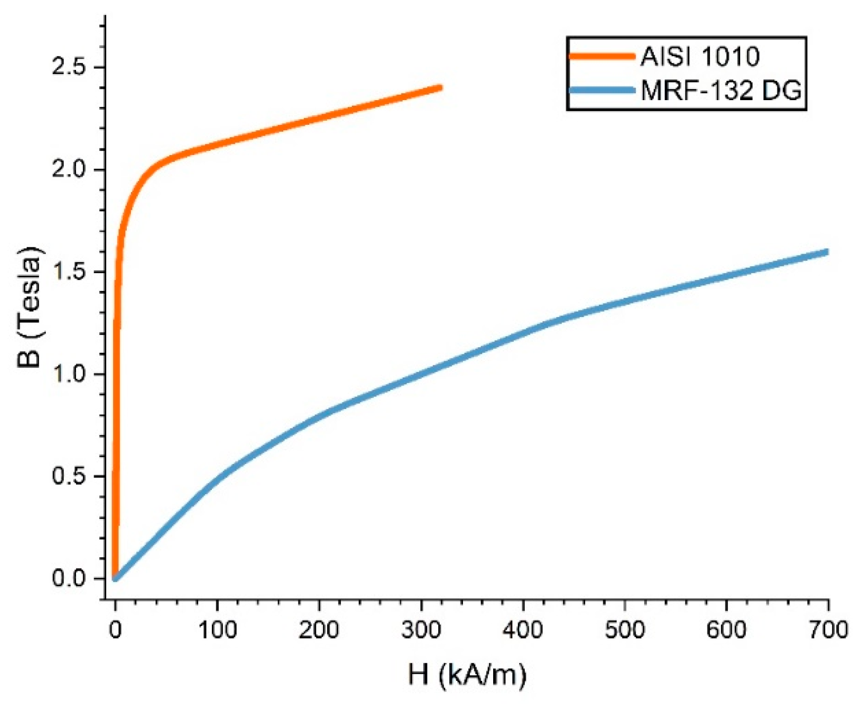
| Magnetic permeability of AISI 1010 | H/m | 0.000838694 | |
| Magnetic permeability of air | H/m | 0.000001256 | |
| Magnetic permeability of MRF | H/m | Not-constant | |
| Angular velocity (10 rpm) | rad/s | 1.0467 | |
| Outer valve length | mm | 34.98 | |
| = | Inner valve length = Fluid gap length | mm | 32.58 |
| Coil core length | mm | 11.5 | |
| Coil space length | mm | 5 | |
| Coil chord to coil core length | mm | 3.49 | |
| Outer valve width | mm | 1.5 | |
| Coil core width | mm | 5 | |
| Fluid gap width | mm | 0.5, 0.75, 1 | |
| = | Valve height = Rotor blade height | mm | 22 |
| Coil core height | mm | 8.5 | |
| Inner valve radius | mm | 18 | |
| Rotor shaft radius | mm | 2.5 | |
| Rotor blade radius | mm | 20 (on wgap 0.5) | |
| Valve angle | ° | 110 |
Disclaimer/Publisher’s Note: The statements, opinions and data contained in all publications are solely those of the individual author(s) and contributor(s) and not of MDPI and/or the editor(s). MDPI and/or the editor(s) disclaim responsibility for any injury to people or property resulting from any ideas, methods, instructions or products referred to in the content. |
© 2022 by the authors. Licensee MDPI, Basel, Switzerland. This article is an open access article distributed under the terms and conditions of the Creative Commons Attribution (CC BY) license (https://creativecommons.org/licenses/by/4.0/).
Share and Cite
Lutanto, A.; Ubaidillah, U.; Imaduddin, F.; Choi, S.-B.; Lenggana, B.W. Development of Tiny Vane-Type Magnetorheological Brake Considering Quality Function Deployment. Micromachines 2023, 14, 26. https://0-doi-org.brum.beds.ac.uk/10.3390/mi14010026
Lutanto A, Ubaidillah U, Imaduddin F, Choi S-B, Lenggana BW. Development of Tiny Vane-Type Magnetorheological Brake Considering Quality Function Deployment. Micromachines. 2023; 14(1):26. https://0-doi-org.brum.beds.ac.uk/10.3390/mi14010026
Chicago/Turabian StyleLutanto, Agus, U Ubaidillah, Fitrian Imaduddin, Seung-Bok Choi, and Bhre Wangsa Lenggana. 2023. "Development of Tiny Vane-Type Magnetorheological Brake Considering Quality Function Deployment" Micromachines 14, no. 1: 26. https://0-doi-org.brum.beds.ac.uk/10.3390/mi14010026