
UnpadStat Design: Portable Potentiostat for Electrochemical Sensing Measurements Using Screen Printed Carbon Electrode
 , and
, and
Abstract
:1. Introduction
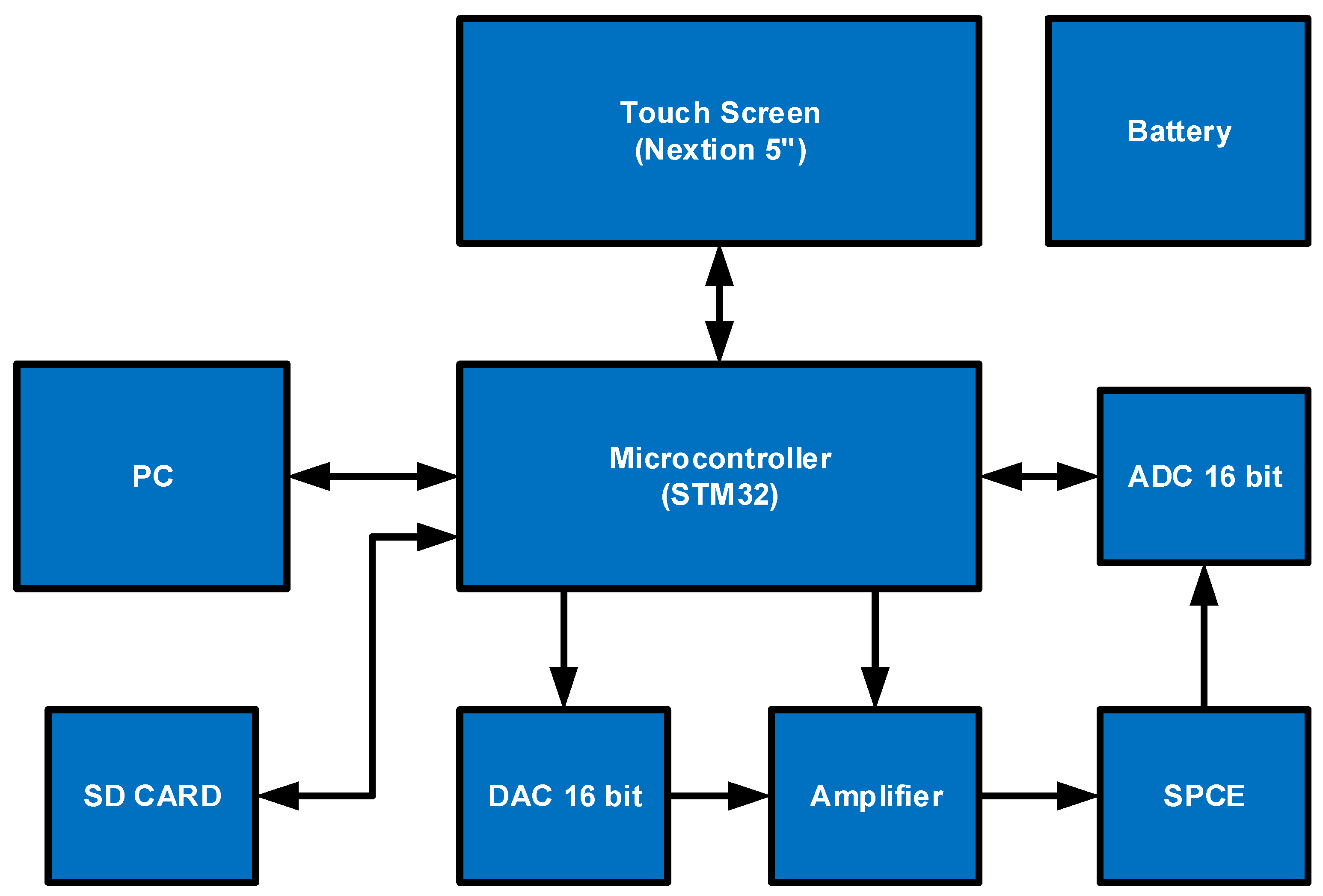
2. UnpadStat Design
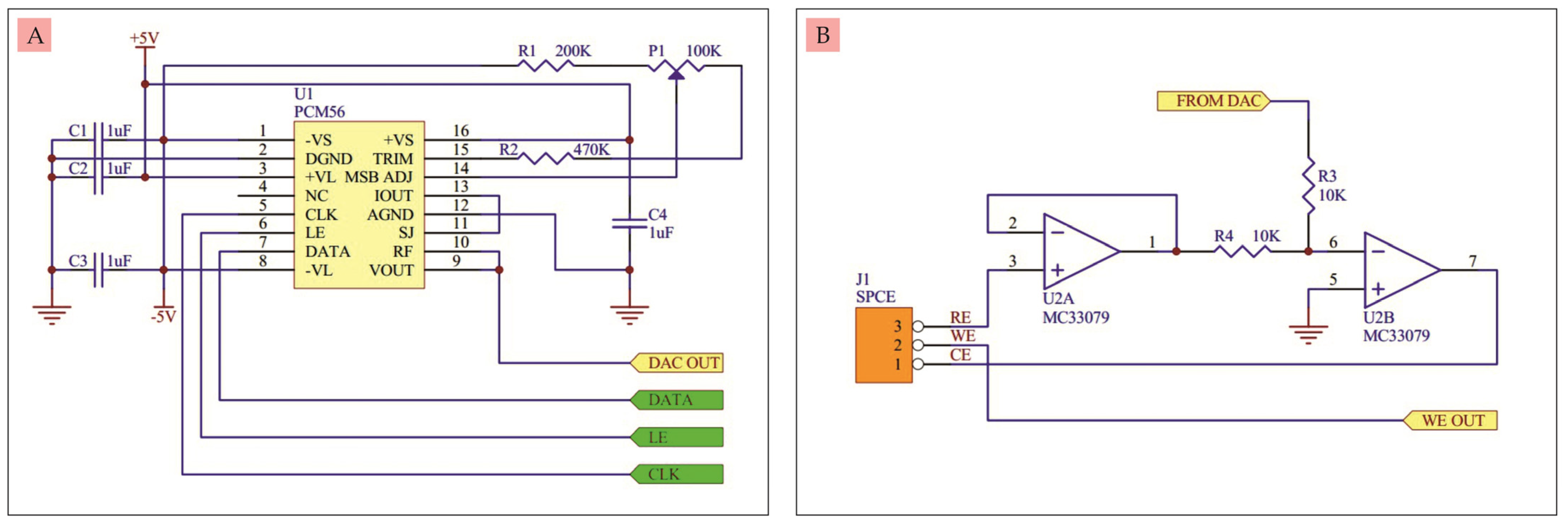
- A.
- DAC
- B.
- Buffer circuit and differential amplifier
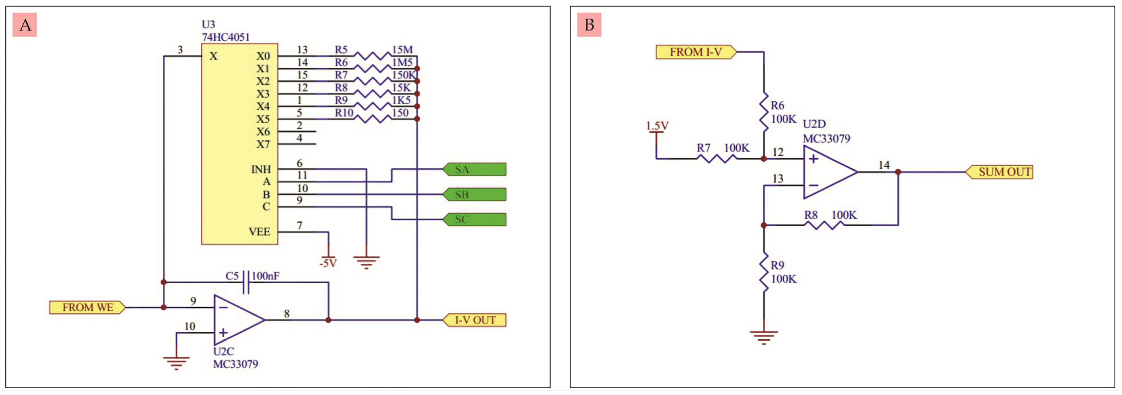
- C.
- Current to voltage converter circuit
- D.
- Positive voltage summing amplifier circuit
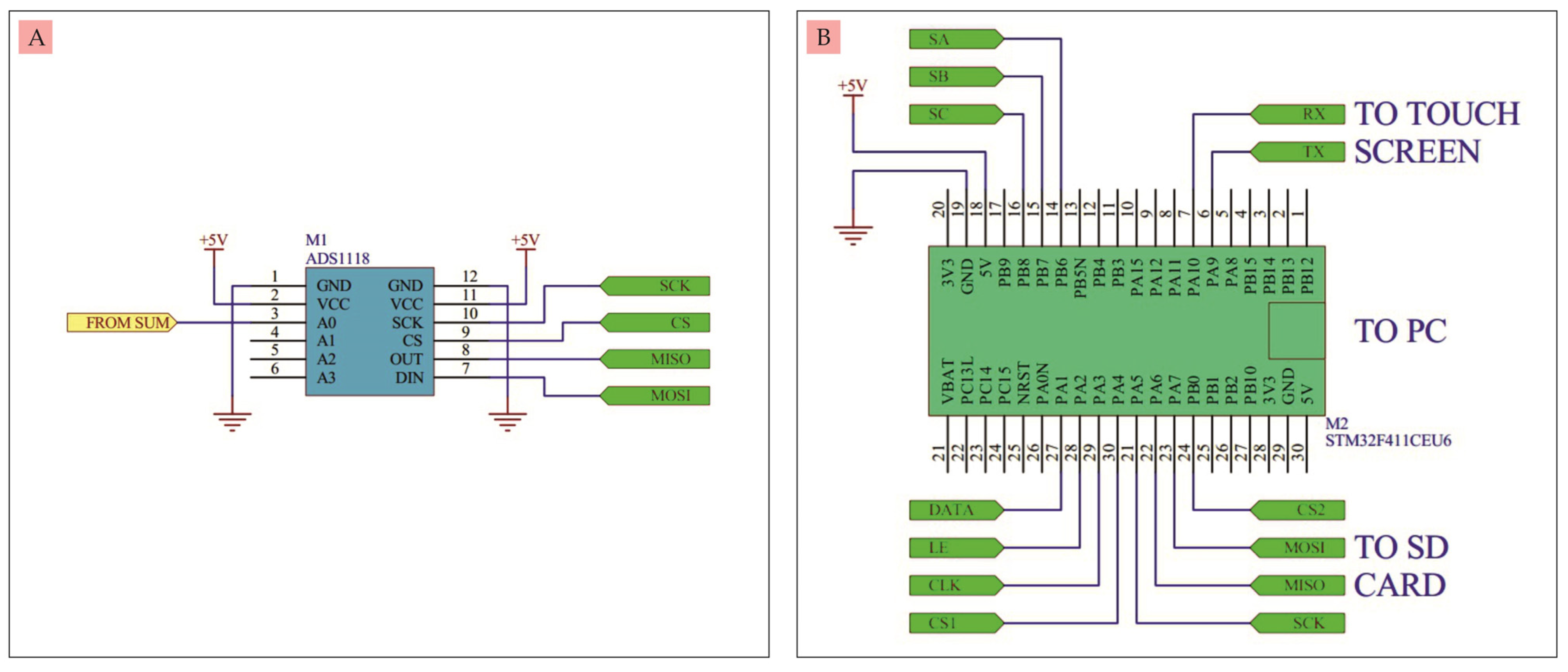
- E.
- ADC
- F.
- Microcontroller
- G.
- Touch screen
- H.
- SD card
- I.
- Battery
3. Results and Discussion
- A.
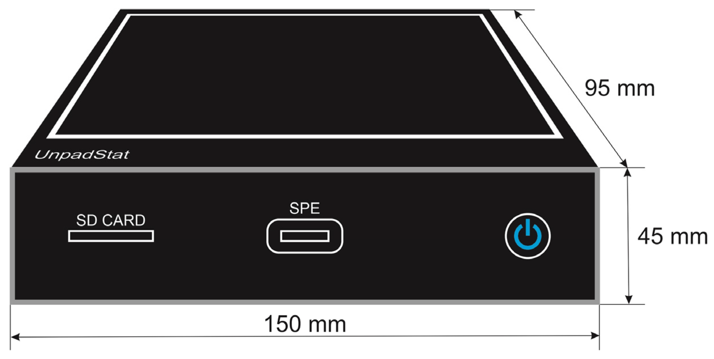
- Casing design
- B.
- Specification
- C.
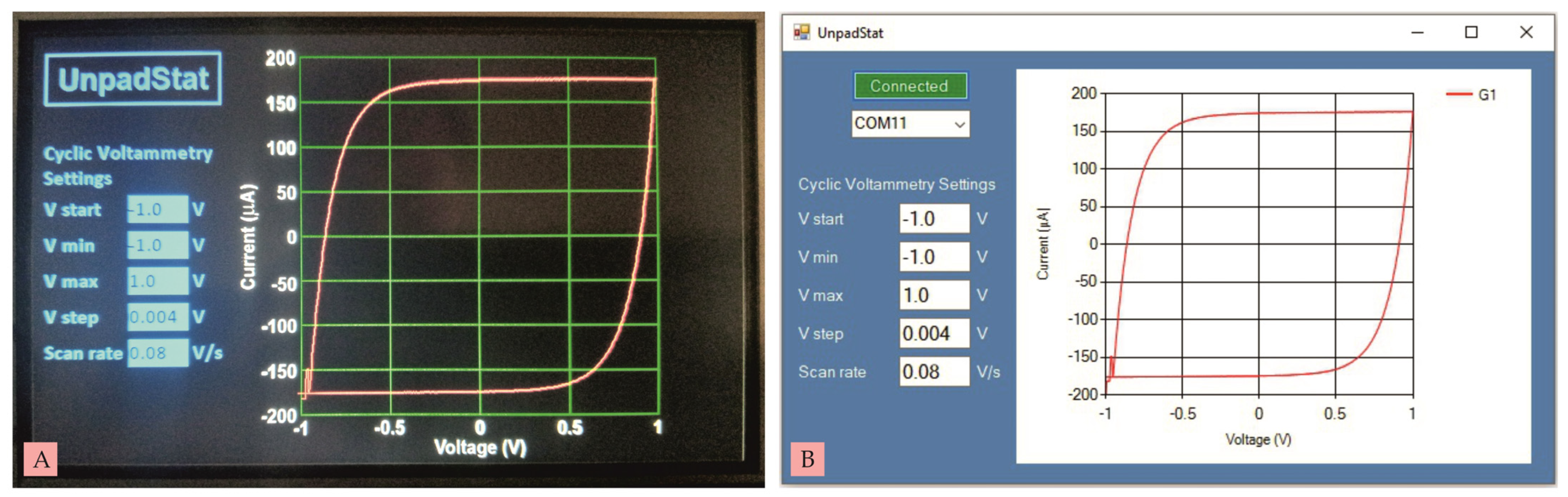
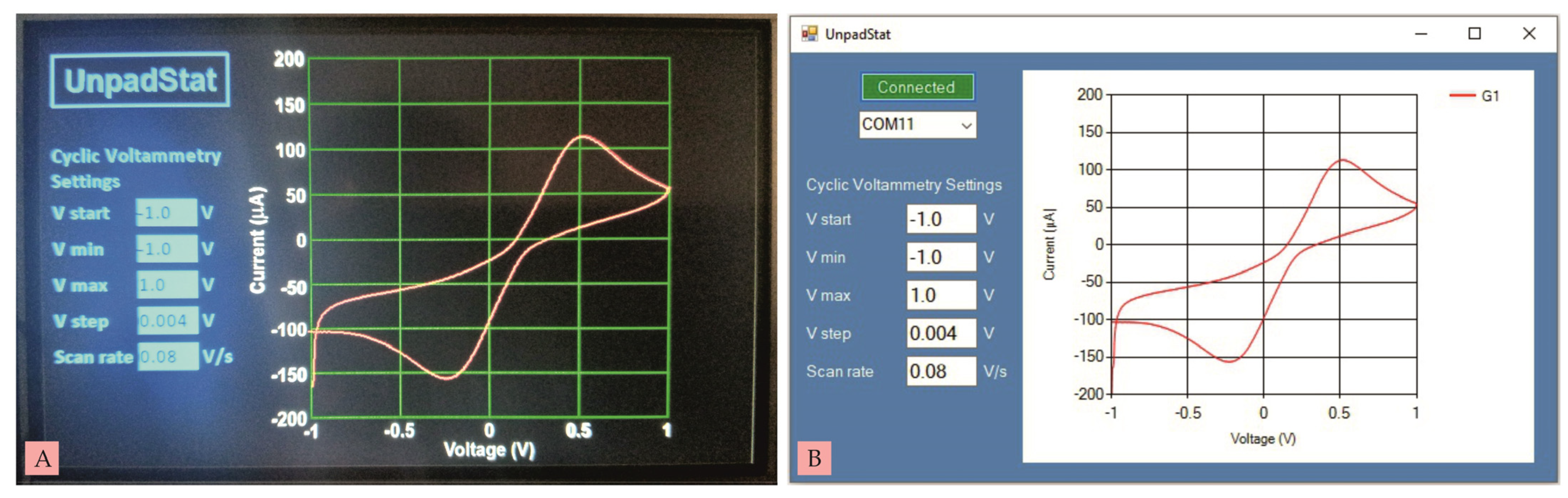
- Testing
4. Conclusions
Author Contributions
Funding
Data Availability Statement
Acknowledgments
Conflicts of Interest
References
- Joshi, P.S.; Sutrave, D.S. Building an Arduino based potentiostat and Instrumentation for Cyclic Voltammetry. J. Appl. Sci. Comput. 2016, 5, 162–167. [Google Scholar]
- Glasscott, M.W.; Verber, M.D.; Hall, J.R.; Penergast, A.D.; McKinney, C.J.; Dick, J.E. SweepStat: A build-it-yourself, two-electrode potentiostat for macroelectrode and ultramicroelectrode studies. J. Chem. Educ. 2020, 97, 265–270. [Google Scholar] [CrossRef] [Green Version]
- Dobbelaere, T.; Vereecken, P.M.; Detavernier, C. A USB-controlled potentiostat/galvanostat for thin-film battery characterization. HardwareX 2017, 2, 34–49. [Google Scholar] [CrossRef]
- Meloni, G.N. Building a microcontroller based potentiostat: A inexpensive and versatile platform for teaching electrochemistry and instrumentation. J. Chem. Educ. 2016, 93, 1320–1322. [Google Scholar] [CrossRef] [Green Version]
- Rowe, A.A.; Bonham, A.J.; White, R.J.; Zimmer, M.P.; Yadgar, R.J.; Hobza, T.M.; Honea, J.W.; Ben-Yaacov, I.; Plaxco, K.W. CheapStat: An open-source, “Do-It-Yourself” potentiostat for analytical and educational applications. PLoS ONE 2011, 6, e23783. [Google Scholar] [CrossRef] [Green Version]
- Dryden, M.D.M.; Wheeler, A.R. DStat: A Versatile, Open-Source Potentiostat for Electroanalysis and Integration. PLoS ONE 2015, 10, e0140349. [Google Scholar] [CrossRef] [PubMed] [Green Version]
- Huang, C.Y. Design of a Portable Potentiostat with Dual-microprocessors for Electrochemical Biosensors. Univers. J. Electr. Electron. Eng. 2015, 3, 159–164. [Google Scholar] [CrossRef]
- Nordin, N.A.; Jamil, A.J.; Mat Som, A.S.C.; Abdullah, W.F.H.; Zain, Z.M.; Hamid, U.M.A.; Rani, S. Potentiostat Readout Circuit Design for a 3-Electrode Electrochemical Biosensing Measurement System. In Proceedings of the 2016 IEEE 7th Control and System Graduate Research Colloquium (ICSGRC 2016), UiTM Shah Alam, Malaysia, 8 August 2016. [Google Scholar]
- Ainla, A.; Mousavi, M.P.S.; Tsaloglou, M.; Redston, J.; Bell, J.G.; Fernandez-Abedul, M.T.; Whitesides, G.M. Open-source potentiostat for wireless electrochemical detection with smartphones. Anal. Chem. 2018, 90, 6240–6246. [Google Scholar] [CrossRef] [PubMed] [Green Version]
- Ahmad, R.; Surya, S.G.; Sales, J.B.; Mkaouar, H.; Catunda, S.Y.; Belfort, D.R.; Lei, Y.; Wang, Z.L.; Baeumner, A.; Wolfbeis, O.S.; et al. KAUSTat: A wireless, wearable, open-source potentiostat for electrochemical measurements. In Proceedings of the 2019 IEEE Sensors, Montreal, QC, Canada, 27–30 October 2019; pp. 1–4. [Google Scholar]
- Giordano, G.F.; Vicentini, M.B.; Murer, R.C.; Augusto, F.; Ferrão, M.F.; Helfer, G.A.; da Costa, A.B.; Gobbi, A.L.; Hantao, L.W.; Lima, R.S. Point-of-use electroanalytical platform based on homemade potentiostat and smartphone for multivariate data processing. Electrochim. Acta 2016, 219, 170–177. [Google Scholar] [CrossRef]
- Sun, A.; Wambach, T.; Venkatesh, A.G.; Hall, D.A. A low-cost smartphone-based electrochemical biosensor for point-of-care diagnostics. In Proceedings of the 2014 IEEE Biomedical Circuits and Systems Conference (BioCAS), Launsanne, Swizerland, 22–24 October 2014; pp. 312–315. [Google Scholar]
- Heien, M.L.; Farrell, D. Portable Instrument for Field Ready Electrochemical Experimentation. U.S. Patent 2019/0170687 A1, 6 June 2019. [Google Scholar]
- Hartati, Y.W.; Gaffar, S.; Alfiani, D.; Pratomo, U.; Sofiatin, Y.; Subroto, T. A voltammetric immunosensor based on gold nanoparticle-Anti-ENaC bioconjugate for the detection of epithelial sodium channel (ENaC) protein as a biomarker of hypertension. Sens. Bio-Sens. Res. 2020, 29, 100343. [Google Scholar] [CrossRef]
- PCM56P Datasheet, Texas Instruments. Available online: https://www.ti.com/lit/ds/symlink/pcm56.pdf (accessed on 14 May 2021).
- MC33079, Datasheet, STMicroelectronics. Available online: https://www.st.com/resource/en/datasheet/mc33079.pdf (accessed on 3 May 2021).
- 74HC4051 Datasheet, Texas Instruments. Available online: https://www.ti.com/lit/ds/symlink/cd74hc4051.pdf?ts=1663563794461&ref_url=https%253A%252F%252Fwww.ti.com%252Fproduct%252FCD74HC4051 (accessed on 21 July 2021).
- ADS1118 Datasheet, Texas Instruments. Available online: https://www.ti.com/lit/pdf/sbas457 (accessed on 30 June 2022).
- STM32F411CEU6, Datasheet, STMicroelectronics. Available online: https://www.st.com/resource/en/datasheet/stm32f411re.pdf (accessed on 2 July 2022).
- NX8048K050, Datasheet. Available online: https://nextion.tech/datasheets/nx8048k050/# (accessed on 25 July 2021).


| No | Microcontroller | Measurement Methode | Communication Interfaces | Own Display | SD Card/ Flashdisk | Ref. |
|---|---|---|---|---|---|---|
| 1 | Arduino Mega2560 | CV | USB | - | Flashdisk | [1] |
| 2 | Teensy 3.2 | CV, LSV, chronoamperometry, chronocoulometry | USB | - | - | [2] |
| 3 | PIC16F1459 | CV | USB | - | - | [3] |
| 4 | Arduino Uno | CV, chronoamperometry | USB | - | - | [4] |
| 5 | AVR XMEGA | CV, LSV, SWV | USB | - | - | [5] |
| 6 | AVR XMEGA | CV, SWV, DPV | USB | - | - | [6] |
| 7 | C8051F005 | CV, LSV, DPV, amperometry, potentiometry | USB | - | SD card | [7] |
| 8 | Microcontroller 32 bit | CV, DPV | USB | - | - | [8] |
| 9 | RFduino | CV, SWV, chronoamperometry, potentiometry | Bluetooth | - | - | [9] |
| 10 | Unreported | CV | Bluetooth | - | - | [10] |
| 11 | AVR XMEGA | CV, LSV, SWV | Bluetooth | - | - | [11] |
| 12 | PIC16F685 | CV | Microphone | - | - | [12] |
| 13 | Arduino | CV, ASV, LSV, PSV | USB | Touch screen | on board | [13] |
| 14 | STM32F411CEU6 | CV | USB | Touch screen | SD card | This work |
| No | Feature | UnpadStat | Portable Instrument for Field Ready Electrochemical Experimentation |
|---|---|---|---|
| 1 | Battery life | 14 h include touch screen | 52 h |
| 2 | Sweep rate limit | ±10–100 mV/s | ±10–400 mV/s |
| 3 | Sweep value limit | ±3 V | ±2.5 V |
| 4 | Voltage step | ±0.1–100 mV | unreported |
| 5 | Variable gain | 6 gain levels | 14 gain levels automated |
| 6 | Linear dynamic range | ±100 nA–10 mA | ±600 pA–1 mA |
| 7 | Storage | up to 32 Gb removable | 32 Gb removable |
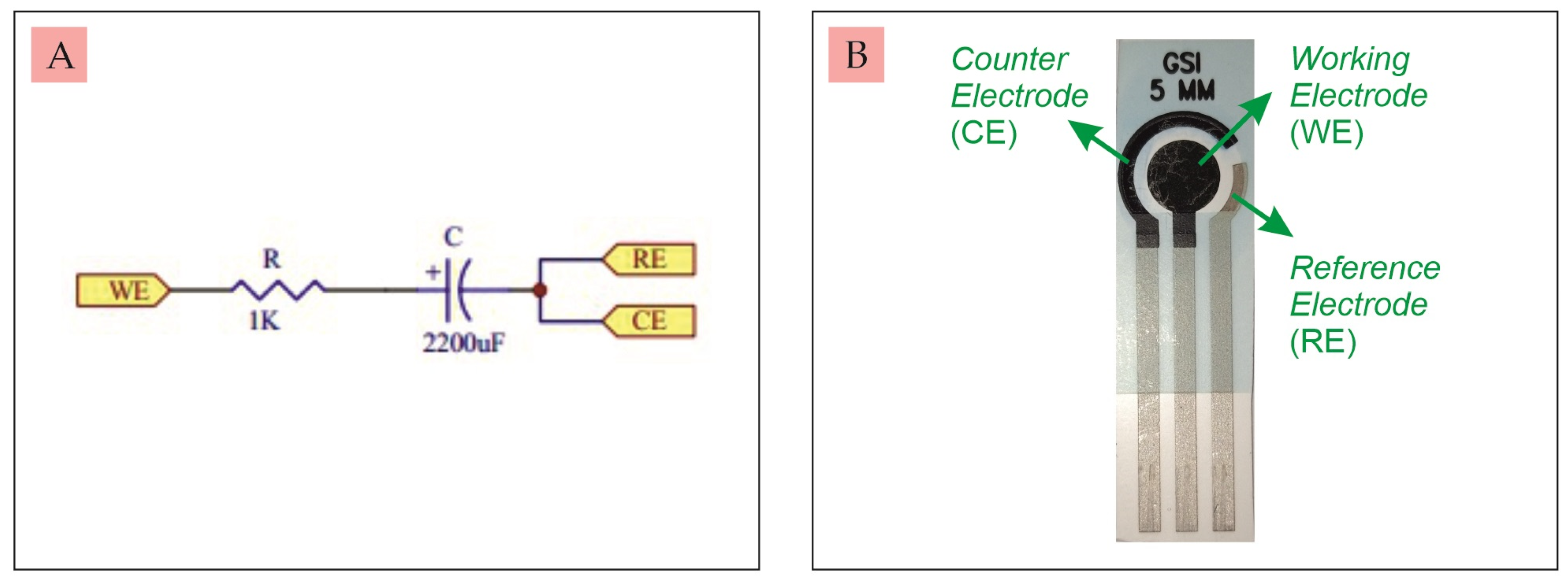
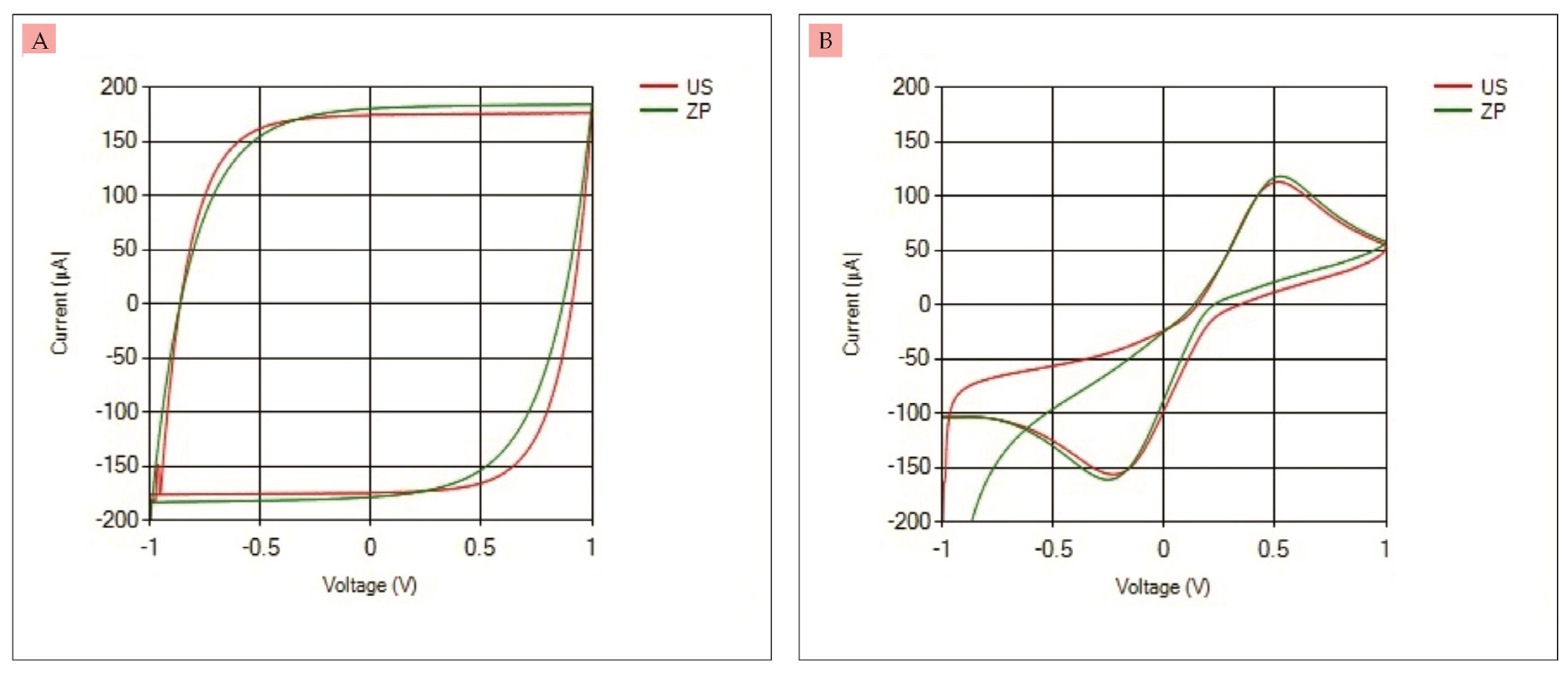
| Dummy Circuit | SPCE Commercial | |
|---|---|---|
| UnpadStat | ||
| Ipa (µA) | 176.64 | 113.13 |
| Ipc (µA) | −176.44 | −156.72 |
| Ana Pot X4—EIS—ZP | ||
| Ipa (µA) | 184.23 | 118.26 |
| Ipc (µA) | −183.56 | −161.25 |
| UnpadStat accuracy relative to Ana Pot X4—EIS—ZP | ||
| Ipa (%) | 95.88 | 95.66 |
| Ipc (%) | 96.12 | 97.19 |
Disclaimer/Publisher’s Note: The statements, opinions and data contained in all publications are solely those of the individual author(s) and contributor(s) and not of MDPI and/or the editor(s). MDPI and/or the editor(s) disclaim responsibility for any injury to people or property resulting from any ideas, methods, instructions or products referred to in the content. |
© 2023 by the authors. Licensee MDPI, Basel, Switzerland. This article is an open access article distributed under the terms and conditions of the Creative Commons Attribution (CC BY) license (https://creativecommons.org/licenses/by/4.0/).
Share and Cite
Setiyono, R.; Lestari, T.F.H.; Anggraeni, A.; Hartati, Y.W.; Bahti, H.H. UnpadStat Design: Portable Potentiostat for Electrochemical Sensing Measurements Using Screen Printed Carbon Electrode. Micromachines 2023, 14, 268. https://0-doi-org.brum.beds.ac.uk/10.3390/mi14020268
Setiyono R, Lestari TFH, Anggraeni A, Hartati YW, Bahti HH. UnpadStat Design: Portable Potentiostat for Electrochemical Sensing Measurements Using Screen Printed Carbon Electrode. Micromachines. 2023; 14(2):268. https://0-doi-org.brum.beds.ac.uk/10.3390/mi14020268
Chicago/Turabian StyleSetiyono, Riyanto, Tias Febriana Hanifa Lestari, Anni Anggraeni, Yeni Wahyuni Hartati, and Husein Hernadi Bahti. 2023. "UnpadStat Design: Portable Potentiostat for Electrochemical Sensing Measurements Using Screen Printed Carbon Electrode" Micromachines 14, no. 2: 268. https://0-doi-org.brum.beds.ac.uk/10.3390/mi14020268