
Design of CAN Bus Communication Interfaces for Forestry Machines
by
 , and
, and
Geoffrey Spencer
1, 
Frutuoso Mateus
1,
Pedro Torres
1,2,* ,
,
Rogério Dionísio
1,3,4 and
and
Ricardo Martins
5 1
Instituto Politécnico de Castelo Branco, 6000-084 Castelo Branco, Portugal
2
SYSTEC-Research Center for Systems & Technologies, 4200-465 Porto, Portugal
3
DiSAC–R&D Unit for Digital Services, Applications and Content, 6000-767 Castelo Branco, Portugal
4
INESC TEC-Institute for Systems and Computer Engineering, Technology and Science, 4200-465 Porto, Portugal
5
Cutplant Solutions, S.A., 6000-459 Castelo Branco, Portugal
*
Author to whom correspondence should be addressed.
Computers 2021, 10(11), 144; https://0-doi-org.brum.beds.ac.uk/10.3390/computers10110144
Submission received: 29 September 2021
/
Revised: 28 October 2021
/
Accepted: 3 November 2021
/
Published: 8 November 2021
Abstract
:This paper presents the initial developments of new hardware devices targeted for CAN (Controller Area Network) bus communications in forest machines. CAN bus is a widely used protocol for communications in the automobile area. It is also applied in industrial vehicles and machines due to its robustness, simplicity, and operating flexibility. It is ideal for forestry machinery producers who need to couple their equipment to a machine that allows the transportation industry to recognize the importance of standardizing communications between tools and machines. One of the problems that producers sometimes face is a lack of flexibility in commercialized hardware modules; for example, in interfaces for sensors and actuators that guarantee scalability depending on the new functionalities required. The hardware device presented in this work is designed to overcome these limitations and provide the flexibility to standardize communications while allowing scalability in the development of new products and features. The work is being developed within the scope of the research project “SMARTCUT—Remote Diagnosis, Maintenance and Simulators for Operation Training and Maintenance of Forest Machines”, to incorporate innovative technologies in forest machines produced by the CUTPLANT S.A. It consists of an experimental system based on the PIC18F26K83 microcontroller to form a CAN node to transmit and receive digital and analog messages via CAN bus, tested and validated by the communication between different nodes. The main contribution of the paper focuses on the presentation of the development of new CAN bus electronic control units designed to enable remote communication between sensors and actuators, and the main controller of forest machines.
1. Introduction
Industry digitalization, based on the industry 4.0 concept, has truly revolutionized the way that manufacturers and consumers look for a product and manage their expectations. Companies are confronted by a series of technological challenges related to Industrial Internet of Things (IIoT) platforms, cloud computing, big data, machine learning, and others. These technologies and concepts are increasingly being added to production processes and appearing in the final product. The forestry sector is no exception since it is also adopting the concept of the fourth industrial revolution into its methodology of work. Particularly, manufacturers of forestry tools that need to produce increasingly technologically advanced equipment are now adapting their production lines to respond to today’s requirements. Thus arrives the concept of forestry 4.0 or intelligent precision forestry, considering more modular, intelligent, and interoperable products [1]. Machines that operate in the forest can communicate with each other and with the supervisory infrastructure, whether they belong to the machine owner, its producer, or repair station. This interoperability allows for more effective management of machine productivity, as well as monitoring equipment and implementing predictive maintenance techniques [2,3]. This concept, associated with machine to machine (M2M) communications and cyber-physical systems [4], is also beginning to make sense of how forest machines lead to other important issues related to tele-maintenance and tele-assistance [5].
Cutplant Solutions SA (https://envicort.netsigma.pt, accessed on 29 September 2021) is a Portuguese company that produces forestry machines under the VICORT brand, where its forest harvesters stand out. VICORT is already consolidated in the Iberian market and shows increased projection in international markets, such as Brazil and Indonesia. The company seeks an increasingly consolidated expression internationally and, for this, works continuously in the development of products to meet the technological needs of current consumers. Under this premise, a new project is underway to allow remote access to forest machines via a mobile communication network (LTE), for operation monitorization, remote assistance, and maintenance. In this scope, the company is seeking new hardware modules for communication between sensors and actuators installed in the forestry tool and the controller installed in the harvester cabin. The need for these modules is related to the demand for a standardization of communications, enabling remote access to machine sensors and actuators, as well as flexibility and scalability in the installation of new sensors/actuators whenever there is a need to upgrade the machines.
With these hardware modules, the company intends to implement CAN bus communication in the different pieces of equipment it produces, such as processor heads and forestry fillers. Currently, some of these pieces of equipment do not “talk” via any communication protocols, as they are wired connections. Others already communicate via a CAN bus through commercial I/O devices; however, they are devices with a fixed number of I/O, thus not allowing an increase in function with new needs. This aspect conditions the developments, since it is dependent on standard market solutions, not flexible, and misaligned with the needs of this kind of machine. As an example, in a machine where an I/O module with eight ports is installed, if one more input is needed, another module with eight ports needs be installed to use only one port. It is necessary that the modules can grow unit by unit.
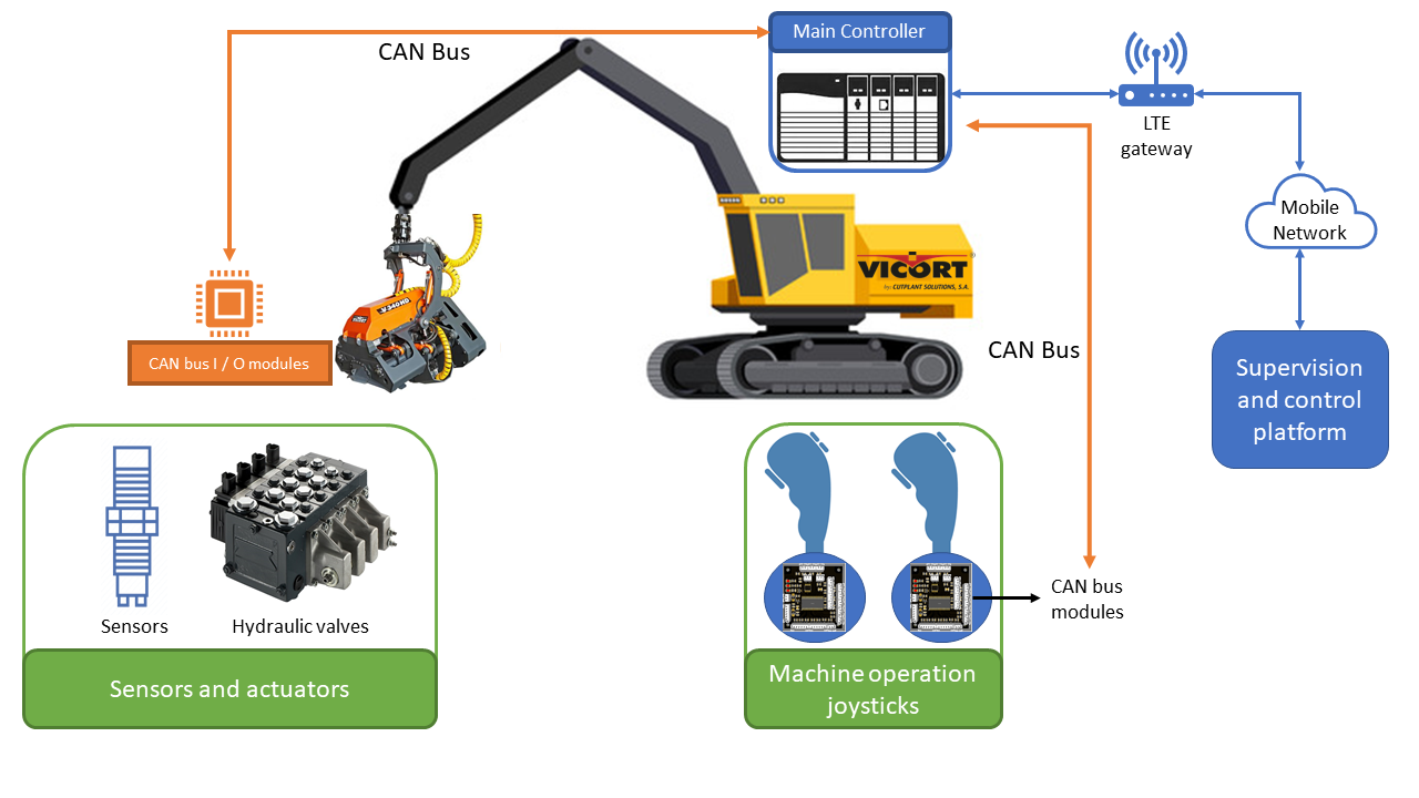
Figure 1 shows a harvester in operation equipped with a processor head, one of the machines that has benefited from the development of CAN bus modules.
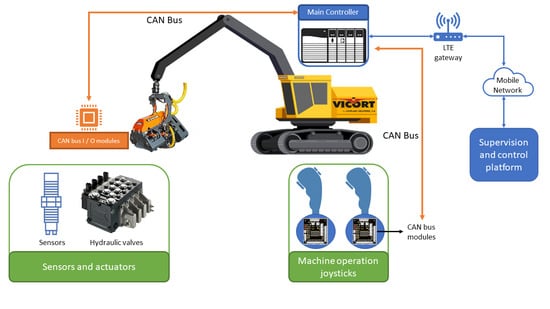
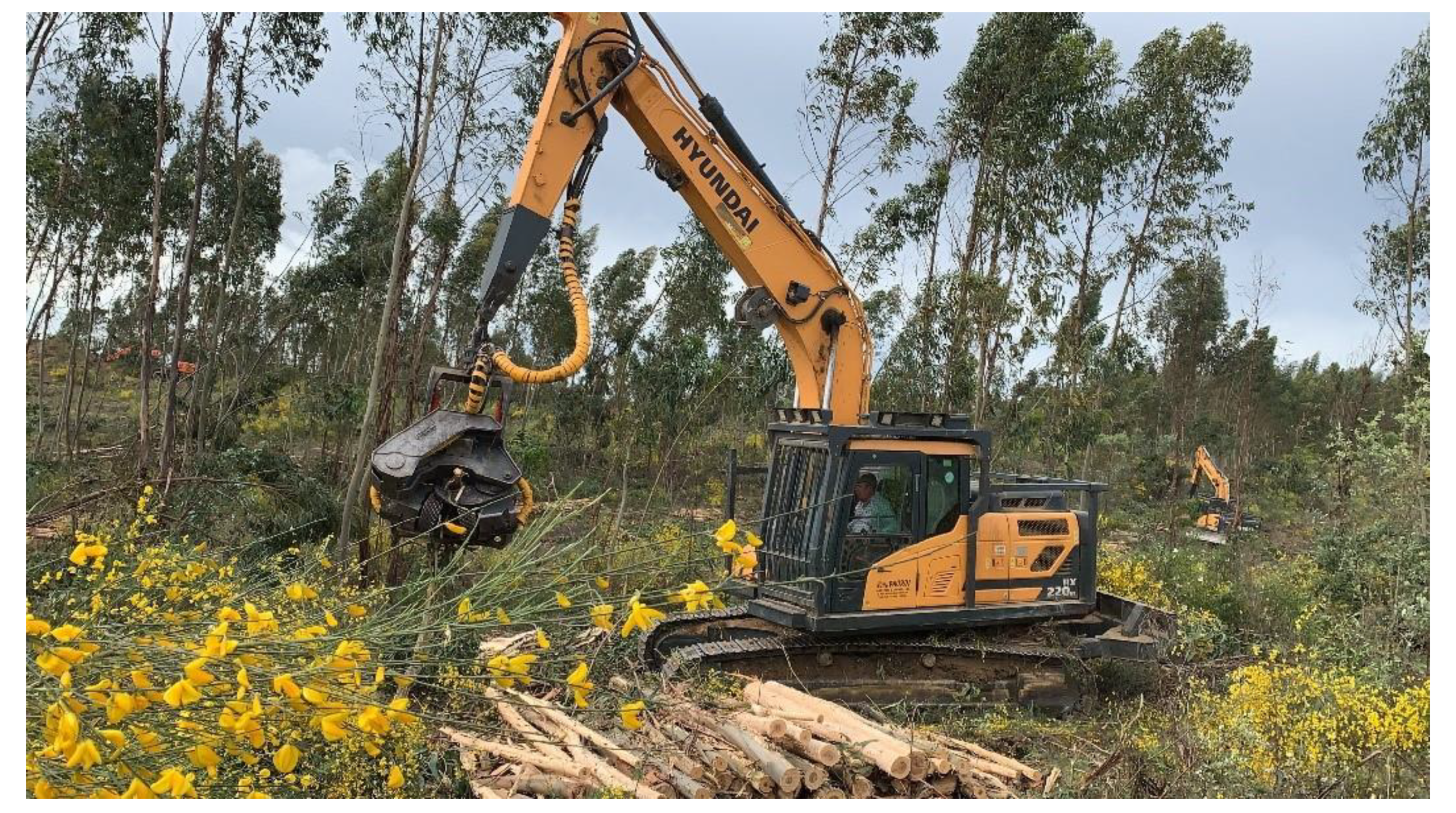
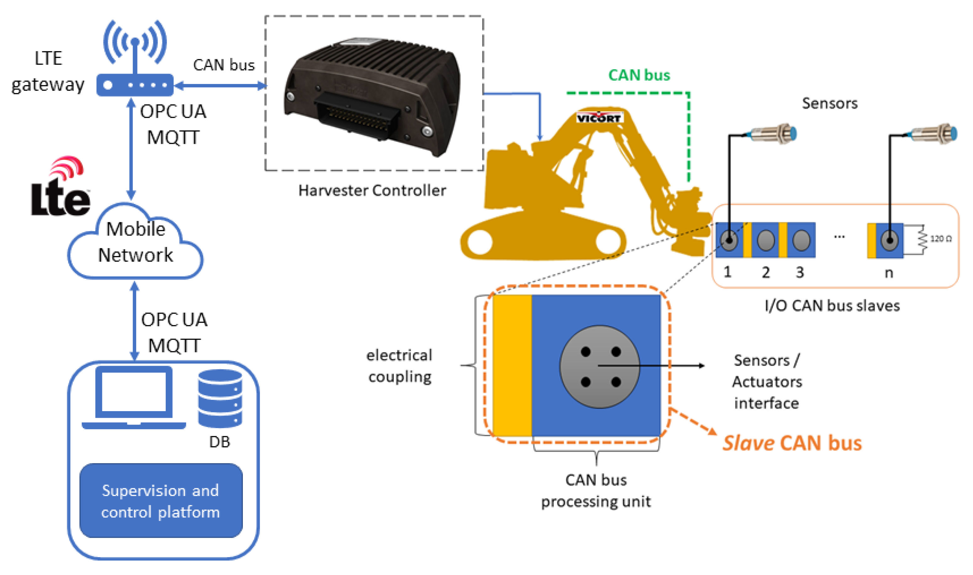
Verifying the need of Cutplant’s Solutions SA to interconnect sensors and actuators of its forestry equipment to the machine controller, the study aims to develop CAN bus modules, modular for a unit, capable of allowing the construction of I/O modules in array, as seen below in Figure 2.
These modules will allow the equipment to have greater flexibility when needed to add new sensors/actuators, in addition to standardizing the communication between the controller and the processing machine, also reducing the existing cabling to only four cables; two for power supply, and a twisted-pair wire for communications (CAN high and CAN low). These communication modules also allow remote access to sensors and actuators in tele-maintenance and tele-assistance scenarios. With the machines operating in the forest, access is made through a mobile communications network, where an LTE/CAN bus gateway is used, enabling remote access to the machine devices, communicating with supervision and control platforms through OPC UA or MQTT.
The remainder of this paper is organized as follows: Section 2 describes the state of the art and related works. Section 3 describes the materials and methods for enhanced CAN bus communications and hardware developments. Section 4 presents the experimental results achieved and, finally, Section 5 presents the conclusions and future work.
2. Related Works
This section is intended to provide an overview of applications that use CAN bus, including market solutions for hardware modules intended for interfacing with sensors and actuators.
The CAN bus is an extremely robust serial communication protocol, based on messages and not addresses, meaning the messages are transmitted by a node on the CAN bus and it is up to a receiving node to determine if it will react to the message or not. It has a multi-master structure, where each node can send and receive messages and allows for a peer-to-peer or master-slave style of communication.
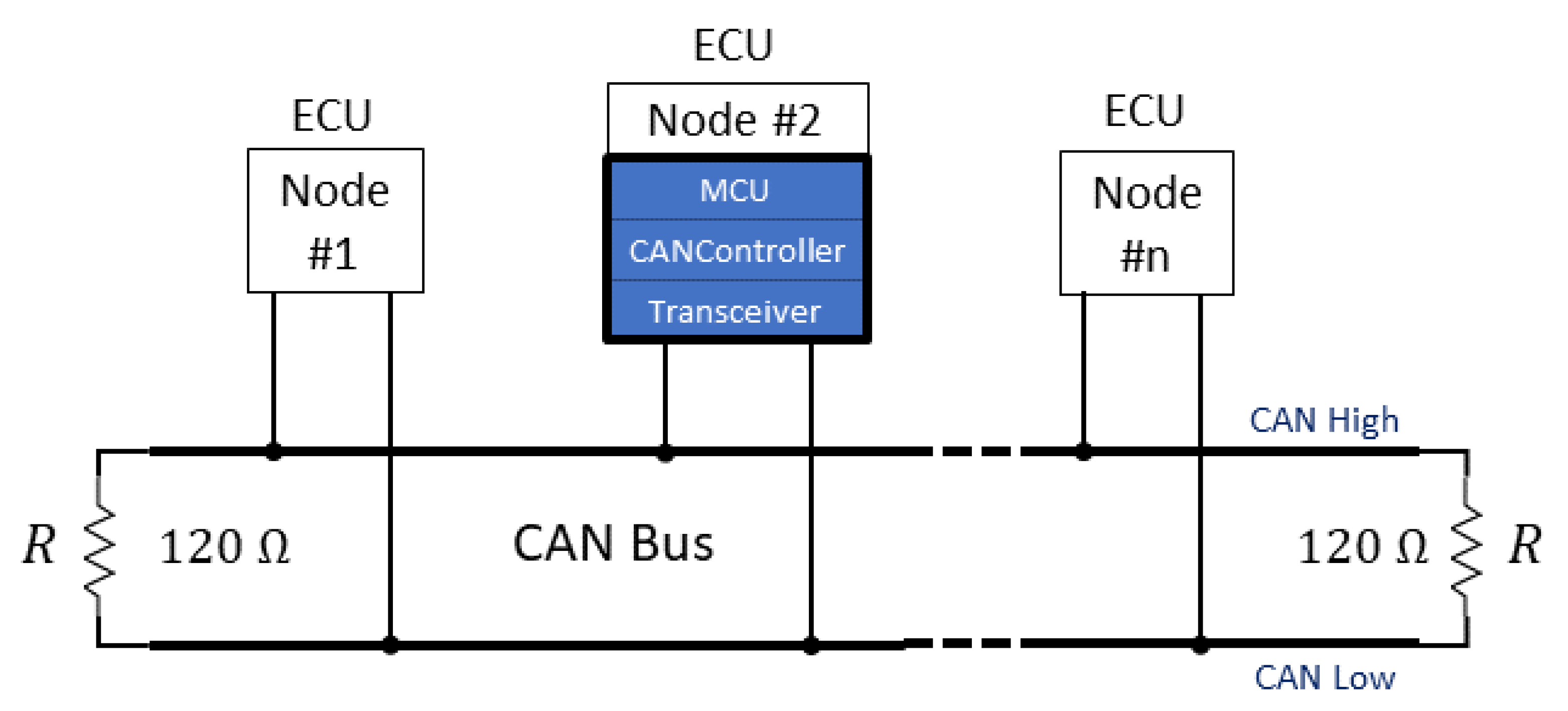
The CAN bus is constituted of a twisted-wire pair, a terminal resistance of 120 Ω and nodes that are formed, in general, by a microcontroller unity (MCU) that is seen as the brain of the node for controlling all procedures and connects electronic devices (sensors and actuators) to the CAN bus. A CAN controller is responsible for the conversion of data provided by the MCU into a CAN message frame or into MCU readable data. It also contains a transceiver that detects and drives data from the bus, converting the single-ended logic used by the CAN controller to a differential voltage signal transmitted on the CAN bus and vice versa.
CAN bus was initially designed to be applied in the automotive industry to provide better and more efficient communication of automotive networks at a lower cost. However, with the advances of technology, CAN became suitable for many other applications in different branches of technologies. In [6], a master-slave control strategy of a microgrid over CAN bus is presented, to control parallel DC/AC inverters. In [7], CAN is used as a means of communication in the control of velocity and position in motor driver modules, to overcome the limitations of RS-232 and RS-485. In [8], a CAN bus based human motion capture analysis system is presented to provide data support for a motion recognition algorithm to help elderly people walk normally. In [9], a scheme for PLC accessing the CAN bus network is presented, based on a 32 bits microcontroller. In [10], an interface USB module is presented to connect a computer directly to the CAN bus network to provide CAN data analysis. In [11], the authors present a multi-node calibration system for CAN bus networks. In the field of autonomous vehicles, a CAN bus has an important role as a means of communication between sensors and actuators installed on vehicles, and in [12] the authors present electronic control units (ECU) that communicate via CAN bus in tests of self-driving cars. In [13], an electrical control system based on CAN bus for thermoelectric plants is proposed, where sensor signals are collected in real time and the pressure in the network is controlled by a microcontroller. In [14], the authors present a gateway implementation for remote monitoring, management, and fault diagnosis of vehicles, performing the connection between the vehicle CAN bus network and mobile communication network. In [15], CAN bus is used in satellite systems as a means of communication between different modules to provide redundancy and a fault-tolerant system.
There are several ECUs and data acquisition modules on the market that allow for interfacing with sensors and actuators through the CAN bus protocol. Parker (https://www.parker.com, accessed on 29 October 2021) and Danfoss (https://www.danfoss.com, accessed on 29 October 2021) are two of the principal manufacturers that have specialized equipment (controllers, sensors, actuators, CAN bus I/O modules) dedicated to industrial machines. However, there are other solutions that can be used, such as modules for digital and analog inputs/outputs, and gateways from different manufacturers (https://esd.eu/en/products/io-modules, accessed on 29 October 2021). The main issue with these commercial modules is that they are built with a fixed number of I/O, limiting expansion when new signals are needed. Another issue is the robustness needed in hostile environments, such as for harvesters. For reasons such as this, the company VICORT wants its own modules to be flexible and modular, according to customer needs.
3. Materials and Methods
This chapter describes the theoretical concepts of CAN bus communication and the development of the first hardware prototype.
3.1. CAN Bus Concepts
The CAN bus standard allows for communication between various electronic control units (ECU), which are machine components capable of detecting or sharing machine component information, such as sensors or central processing units. Each ECU communicates with all other ECUs via the CAN bus system (multicast transmission), based on two wires, CAN low and CAN high, without complex dedicated wiring. All connected nodes must support the same bit rate and bit timing settings, with transmissions up to 1 Mbit/s being the most common.
The ECUs consist of central processing units (microprocessors), CAN controllers, and transceivers. The microprocessor connects sensors, actuators, and other control devices with the CAN network, and decides what the received messages mean and what messages are transmitted. The CAN controller receives bits or data from the bus and sends them to and from the microprocessor. Lastly, the transceiver converts the CAN bus levels to levels that the CAN controller uses and vice versa. Figure 3 exemplifies a CAN bus network architecture for better understanding of the ECU’s connections.
CAN bus protocol is described as a data link layer (standard ISO 11898-1) and a physical layer (standard ISO 11898-2), both standing in the two lower layers of the Open Systems Interconnection model (OSI 7—a seven-layer conceptual model for communication functions of a telecommunication or computing system).
In general, the CAN bus physical layer defines cable types, bus length, electrical signal levels, node requirements, and terminal resistance values. Main parameters from the ISO 11898-2 are described below [16,17]:
- Baud rate and cable length: The CAN bus handles up to 1 Mbit/s in bit rates (classical CAN) or 5 Mbit/s (CAN FD [18]). The baud rate is inversely proportional to the length of the CAN bus. The maximum cable length allowed when running a baud rate of 1 Mbit/s is 40 m. For 125 kbit/s it is 500 m;
- Termination: Two 120 Ohm resistors must be placed at each extremity of the CAN bus to properly terminate it. The resistors guarantee the perfect propagation of electrical signals through the bus cables. Each resistor allows the reflection of signals which is mandatory for the proper functioning of the CAN bus network.
The data link layer specifies the format of the messages, transmission rules, synchronization of the nodes, detection and error control, prevention of failures mechanism, and four types of frames:
- Data frame: most commonly used, contains data sent from the transmitter to the receiver;
- Remote frame: used to request a message from a node with a designated ID;
- Error frame: is transmitted by any node that detects an error on the bus;
- Overload frame: generates an extra delay to finish the processing of data frames or remote frames.
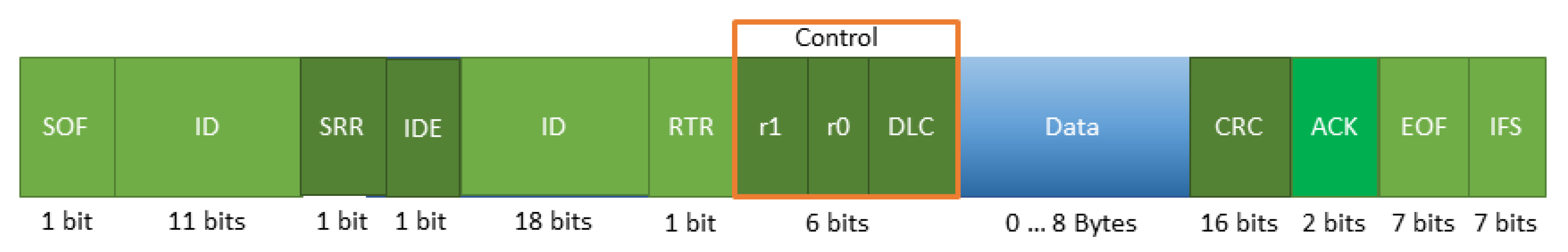
The controller area network introduces two standardized types of protocol, the CAN2.0A (standard) and CAN2.0B (extended). Each differ from one another in the number of identifier (ID) bits contained in the data frame. While CAN2.0A contains an 11-bit identifier, CAN2.0B which is an upgraded version of CAN2.0A, contains a 29-bit identifier, completely compatible with CAN2.0A.
The CAN2.0B can either be “active” or “passive”, meaning the controllers can transmit and receive extended frames, or they can silently discard received extended frames successively.
To better understand the differences between each version, both data frames and corresponding fields are represented in Figure 4 and Figure 5.
- Start-of-frame (SOF): Defined by only one dominant bit ‘0′, this field marks the beginning of the message or frame;
- Identifier: The 11-bit identifier establishes the priority of the message in the CAN network. The lower its binary value, the higher its priority;
- Remote transmission request (RTR): The Remote Transmission Request bit indicates if the frame is a data frame (‘0′) or a remote frame (‘1′);
- Identifier extension bit (IDE): The identifier extension bit determines the size of the identifier. A dominant bit corresponds to an 11-bit identifier;
- Reserved bit (r0): Bit reserved by the standard. Has a default value of ‘0′ but the CAN controllers accept it independently of its logical value;
- Data length code (DLC): Indicates the number of bytes of data (0–8);
- Data: Contains the data bits. Up to 64 bits (8 bytes) can be sent through a data frame;
- Cyclic redundancy check (CRC): Contains the checksum (number of bits transmitted) of the preceding application data for error correction;
- Acknowledgement (ACK): Has two bits (ACK slot and ACK delimiter). The transmitter sends two recessive bits, while the receiver overwrites the recessive bit (ACK slot) if it acknowledges and receives the data correctly;
- End-of-frame (EOF): Delimits each data frame and remote frame by a sequence of flags consisting of seven bits;
- Interframe space (IFS): Moves a correctly received message to a proper buffer by indicating the time requirement;
- Substitute remote request (SRR): In extended format it replaces the RTR bit as a placeholder;
- Identifier extension: A recessive bit that, when sending an extended CAN message, indicates that more identifier bits follow (18-bit extension follows IDE);
- r1: Another bit for possible use in future amendments [19].
3.1.1. CAN Bus Arbitration
CAN is an asynchronous protocol that requires all the nodes to be synchronized to sample every bit at the same time. Therefore, synchronization of all the nodes cannot be performed with an external clock, but with the edge of the first bit of the message (start of frame). A dominant bit ‘0′ overwrites a recessive bit ‘1′, meaning that the dominant bit has electrical priority over the recessive bit. Thus, whenever multiples nodes are trying to transmit a message over the CAN bus, the node with higher priority (lower ID) continues the transmission while the other nodes have their transmissions interrupted, as described in Table 1.
3.1.2. Advantages and Disadvantages of CAN Bus
Advantages:
- Reduction of wires, errors, weight and cost, since there is only one CAN system needed for ECUs to communicate;
- Provides a fully centralized network for ECUs, with master-slave and multicast features;
- It is a robust system once it is not subject to electrical disturbance and electromagnetic disturbance;
- It allows nodes that have lost arbitration to send a message when the bus is free without losing any data and with no interruptions, since CAN has carrier sense multiple access with collision detection (CSMA/CD) and arbitration on message priority (AMP) protocols.
Disadvantages:
- Limits the number of nodes connected to the CAN bus (maximum 64 nodes);
- Possibility of integrity issues;
- Undesirable interaction between the nodes;
- Limited length and amount of data per message;
- High cost for software development and maintenance.
3.2. CAN Bus Module Implementation
This subsection describes the theoretical conceptualization of the electronic developments of our ECU module, the microcontroller as transceiver used, as well some programming aspects.
As the MCU for this study, the microcontroller PIC18F26K83, produced by Microchip Technology Inc., was selected due to its low cost, wide variety of compatible chips, and versatility during the inclusion and exclusion of nodes. Beside these characteristics, the PIC was selected mostly for featuring CAN bus technology with a vast library for the protocol and allow the direct connection to the transceiver through CAN_Tx and CAN_Rx pins that can be configured between the 28-pins the PIC contains, dismissing the CAN controller.
The transceiver MCP2551, also produced by Microchip Technology Inc., is included in the node to perform the match of the bus signal level CAN, to work with the PIC18F26K83 [20], support 1Mbps, and can operate with up to 24 V on the CAN bus, including protection against short-circuit and automatic shutdown. Figure 6 shows a representation of the ECU module developed in this work composed by the MCU, the transceiver for access to the bus, and the RS232 module for communication tests via computer.
CAN low and CAN high pins are directly connected to the CAN bus, requiring a terminal resistance of 120 Ω in parallel between the two pins [19].
To develop, configure, debug, and qualify applications for the MCU, we used the MPLAB X Integrated Development Environment v5.45 along with XC8 Compiler responsible for the conversion from the source code used in MPLAB X IDE (.c) and transformed it into machine language (.hex); that is, into readable data for the MCU.
The extension MPLAB Code Configurator (MCC) is also used as it allows the user to enable and configurate the pins of the MCU and set vast peripherals and functions for the project through an intuitive graphical programming interface.
4. Results
This section presents the experimental results achieved, the first prototype of the board for CAN bus 2.0B communications, a set of experiments carried out to validate the board, and its functionality as a CAN communication node with message priority identification and correct receptions.
4.1. First ECU CAN 2.0 B Prototype
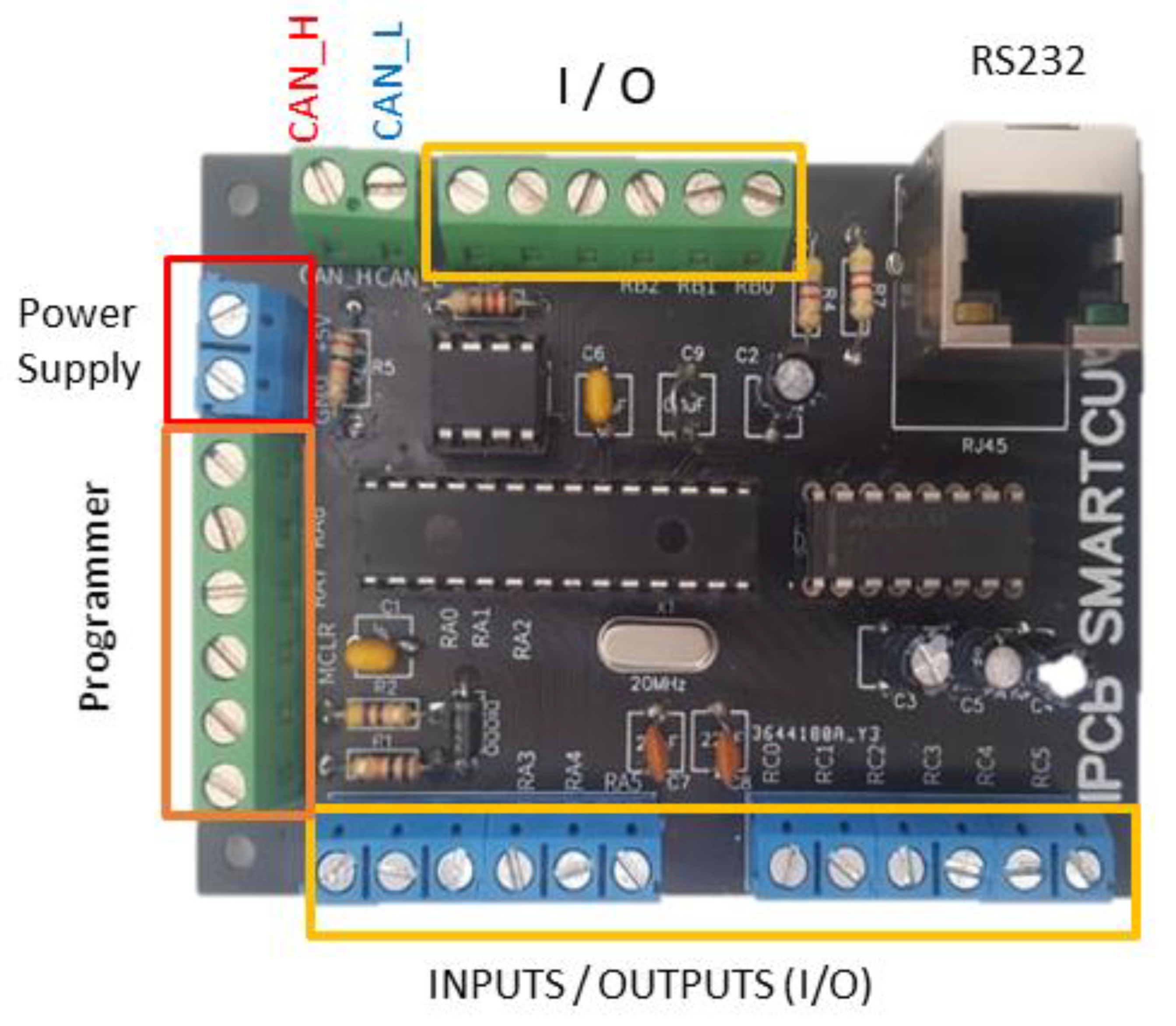
The work presented here led to the development of the first printed circuit board (PCB) “IPCB SMARTCUT V00.2021” of an ECU CAN 2.0 B characterized by flexibility in the acquisition of data from digital and analog inputs/outputs and RS232 communication for data analysis. Figure 7 shows the ECU prototype developed and tested in this work.
Beside a microcontroller, transceiver, MAX RS232, and the RJ45 port included in the board, it also introduces screw terminal blocks with side wire entry angles to connect the wires to the various pins of the microcontroller and to connect:
- Programmer-PICkit 4 (MCLR; +5 V; GND; ICSPDAT; ICSPCLK);
- Power supply (+5 V; GND);
- CAN bus (CAN high; CAN low).
Some pins of the microcontroller are not included in the connector’s terminals, since they are reserved for:
- Clock-out and clock-in to connect to an external oscillator (RA6 and RA7 respectively);
- CAN_Rx and CAN_Tx (RB3 and RB4 respectively);
- ICSPCLK an ICSPDAT (RB6 and RB7 respectively);TXPIC and RXPIC (RC6 and RC7 respectively) to be connected to the MAX232CPE+.
4.2. Second ECU CAN 2.0 B Prototype
The second prototype “IPCB SMARTCUT v02.2021”, designed with an SMD component 0805 type for passive components and SOIC for integrated circuits (microcontroller and transceiver), was developed to be worked in the operation joystick of VICORT machines. With this module, the operating commands from the joysticks are encapsulated in a CAN bus 2.0B message that carries the digital and analog signal messages to the master controller of the machine. The multi-wire cable used in the connection with the controller is now made with a cable of only four wires, and the communications standardized for interaction with the controllers of different brands.
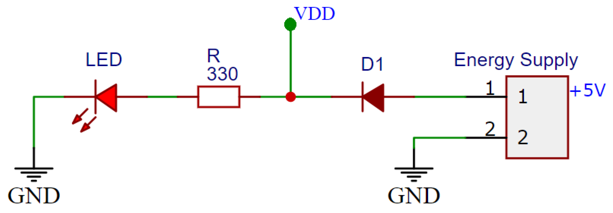
This printed circuit board includes some new features, including polarity shift protection and short circuit protection (Figure 8 and Figure 9), as well as pull-down resistance on the inputs. Two terminals are also available to connect a CAN network analyzer for monitoring and analyzing communication messages through a graphical interface.
The projected module is shown in Figure 10. It is characterized by 14 digital inputs for the joystick buttons and two groups of two analog inputs, plus two digital inputs for the joystick rollers. It has one CAN bus port, one programming port, and works with a +5 V/GND power supply.
4.3. CAN Bus Test Communications Case Study
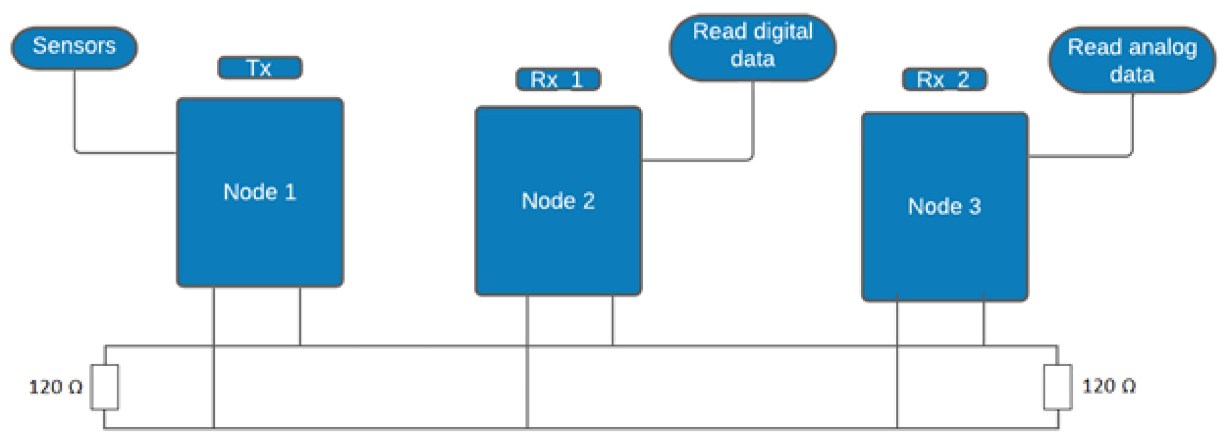
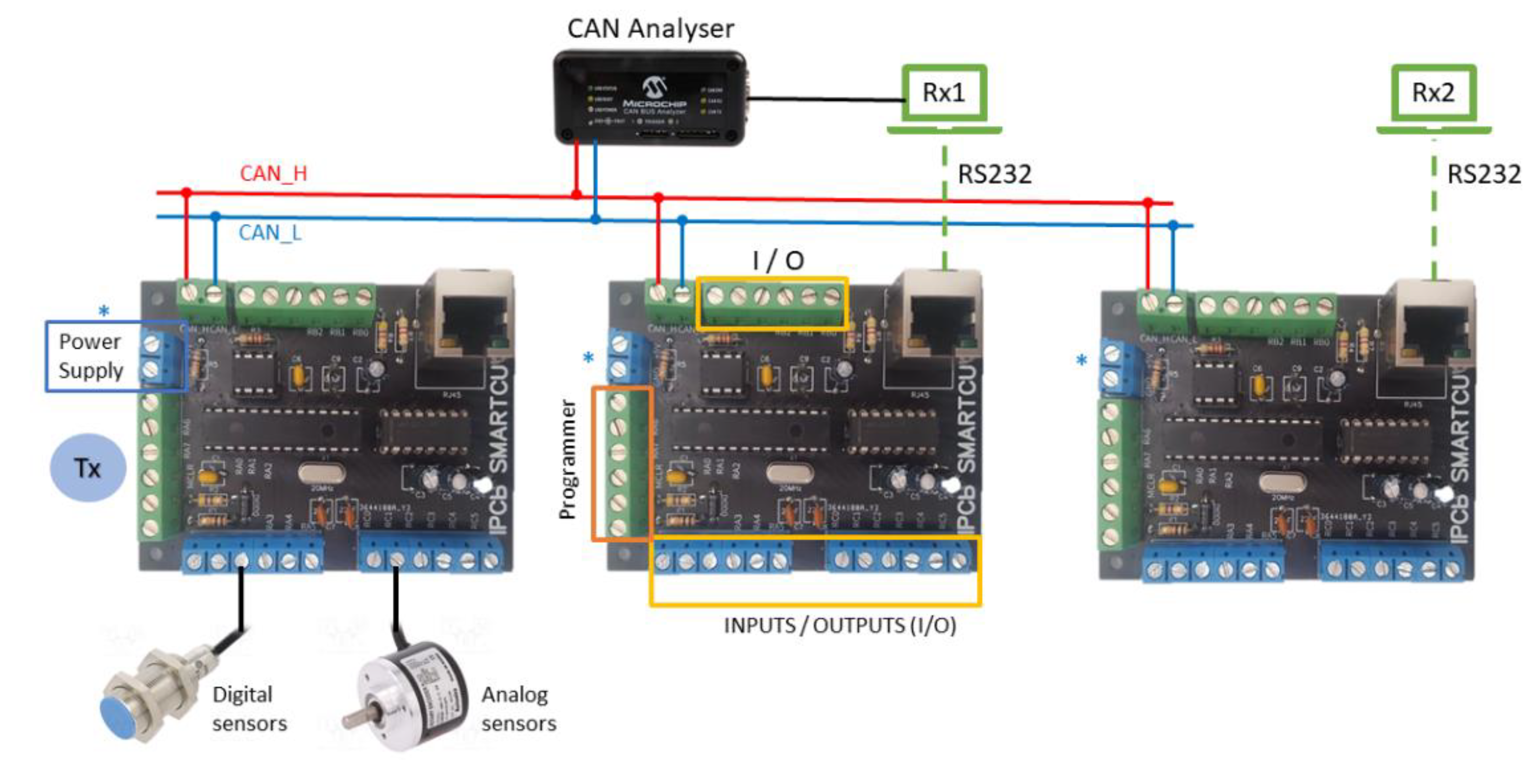
Initially the case study aimed to carry out the transmission of digital and analog signals by using three nodes, where one node was responsible for sending messages carrying an ID with different DLC and data according to the sensor that is activated. The second and third node were designated to receive digital and analog data respectively sent by the transmitter node. The experimental setup for the first case study is shown in Figure 11, and more detailed in Figure 12, where it is used in the first node developed, named “IPCB SMARTCUT v00.2021”.
The experiment in question considered three sensors, two being inductive proximity sensors destined to send digital signals, and a potentiometer to generate and convert an analog signal, the results of which are stored in conversion registers (ADRESL and ADRESH) and then transmitted through the CAN bus.
The first node is the transmitter, thus all the sensors used are connected to it, while the others two nodes are considered as receivers. The second node is configured to receive only digital signals and the third node is configured to receive analog signals with a pulse-width modulation (PWM) output.
The description of the sensors used are shown in the next table, along with their transmission characteristics.
Experimental Results
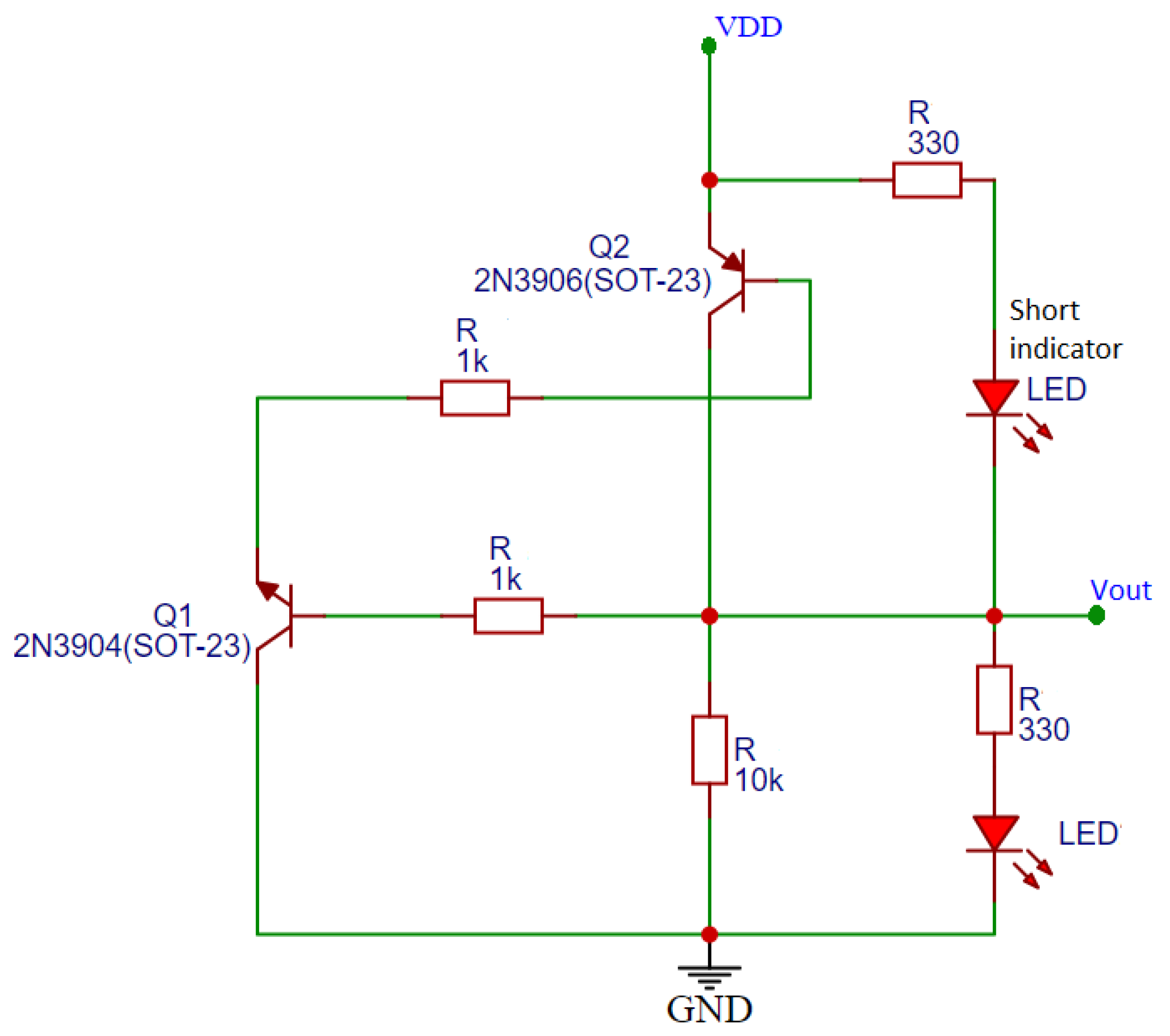
Considering the PCB design, the transmission and reception of messages through CAN bus are characterized by using LEDs connected to the transmitter and receiver nodes, to signalize the transmission and reception of the messages.
The transmitter node is connected to four LEDs to signalize the activation of the sensors mentioned in Table 2. A red LED is connected to signalize the inactivation of the sensors and that no messages are being transmitted to the CAN bus. While the rest of the LEDs signalize the activation and transmission of a message according to the sensor that is activated, one of the LEDs, beside signalizing the analog conversion, allows for the visualization the conversion results as a pulse-width modulation (PWM). When a message is transmitted the red LED switches to a green LED.
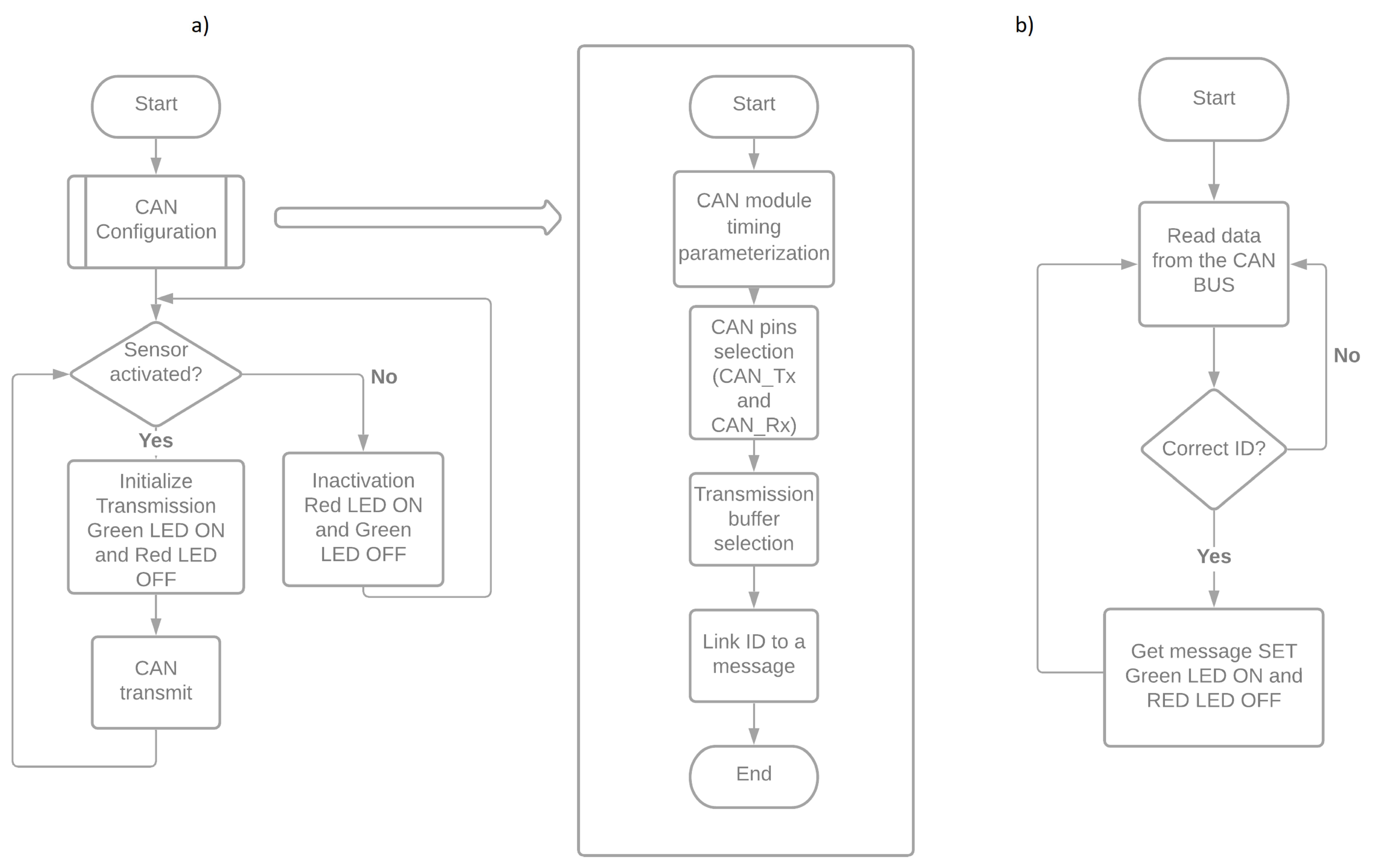
For the receiving nodes the same concept is used, this time to signalize the message reception. The first receiving node has four LEDs in groups of two (red and green) to signalize the reception of a digital signal from the two inductive proximity sensors and the second node with two LEDs; however, the LED that signalizes the reception of the analog conversion has an LED configured as a PWM output to be compared to LEDs from the transmitter node. The process of the transmission and reception of CAN messages are described in the following flowchart in Figure 13.
Although the activation of the electronic devices causes the LEDs to switch from red to green it does not confirm the transmission of a CAN message, because the LEDs can still switch but no message is transmitted. Therefore, to confirm the transmission and the reception of the messages, a CAN Analyzer from Microchip, a hardware that allows direct access to the CAN_High, CAN_Low, CAN_Tx and CAN_Rx was used and visualized data in the software to monitor the CAN bus and confirm the reception of the messages through CAN bus.
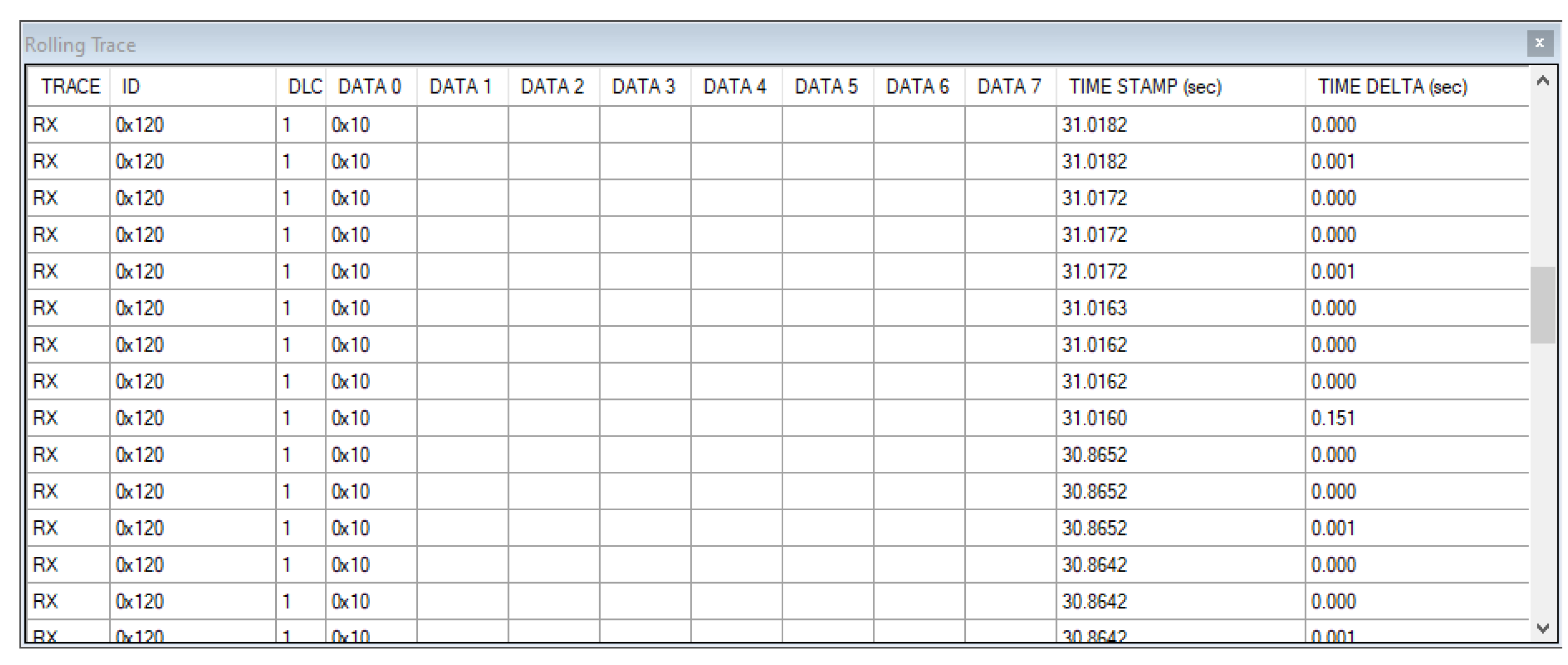
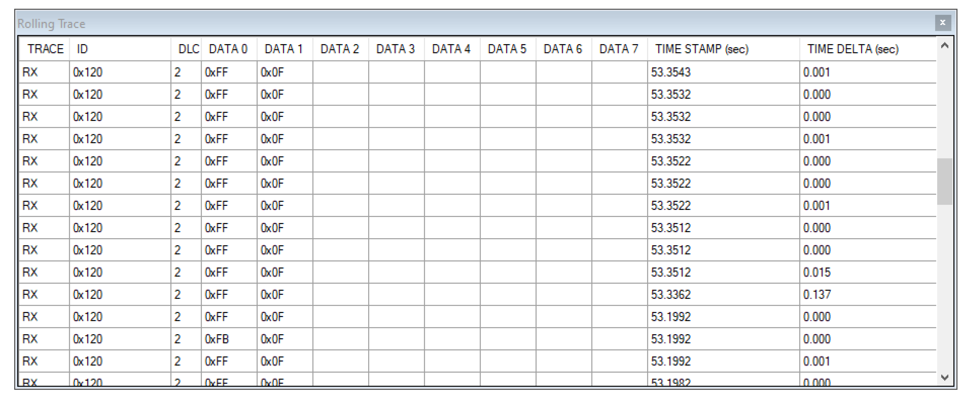
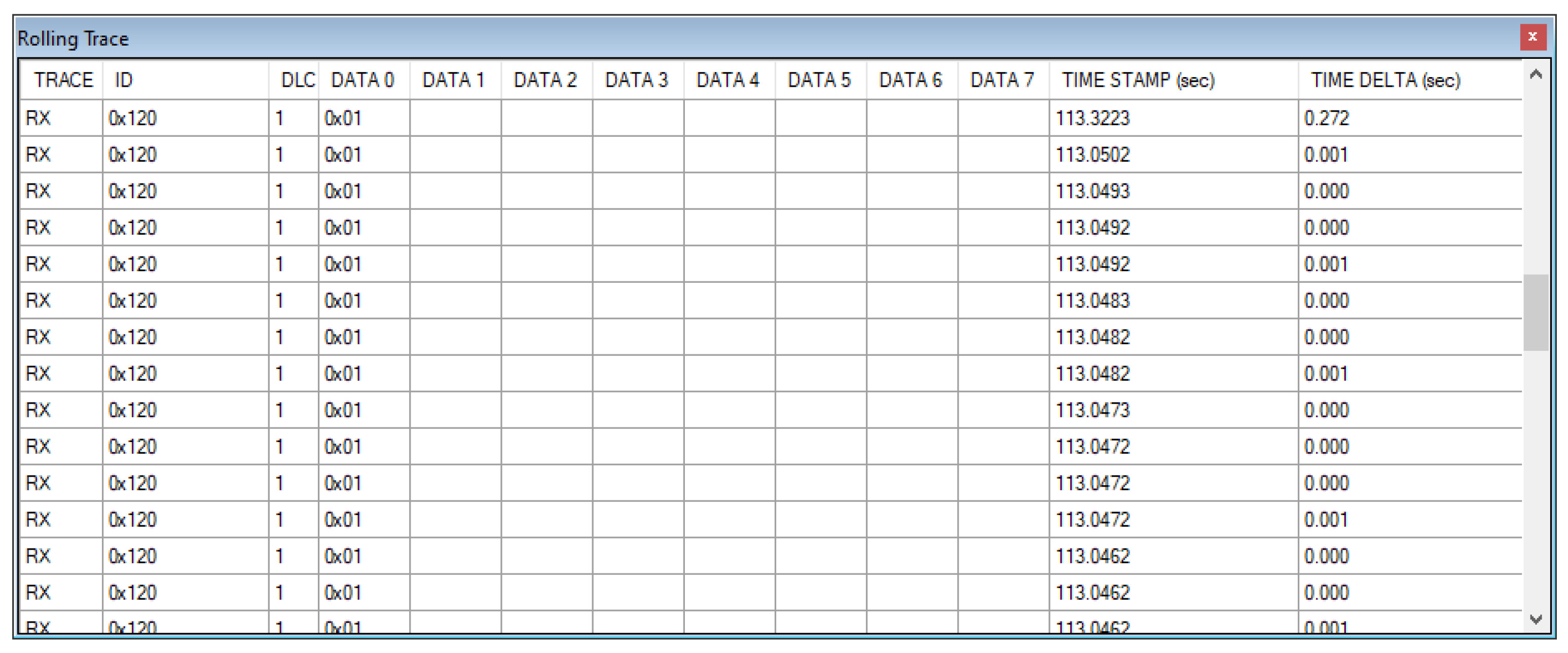
By using this device, it was possible to confirm the reception of the messages transmitted, visualizing the identifier of the message and the data length code. The data that were transmitted are shown in Figure 14, Figure 15 and Figure 16.
Besides confirming the reception of the messages in the corresponding nodes and the parameters defined, CAN Analyzer also provided the time stamp that indicated the moment a CAN message was received and the time delta, which indicated the difference from the last message on the bus based on the last message received regardless of the ID (rolling trace configuration).
5. Conclusions
The focus of this paper was the development of a new hardware module to establish communications via CAN2.0B between devices installed in forest machines. The flexibility of this module allows the construction of ECU arrays useful for building scalable modules for data acquisition that can grow as a function of the number of sensors that need to be installed. The only requirement is to establish different IDs for each ECU. The modules have been successfully tested in communications with the main controller of the harvester, allowing the ability to establish communication between sensors and actuators via a CAN bus instead of multi-wire cables. The modules in their current state are the basis for future developments of new devices that will more compact and capable of meeting all safety and robustness standards to work in hostile environments. The access and the possibility of programming the module make this platform a development and support tool to reach a marketable prototype. Future work in electronics developments will continue, to achieve a more compact device, built with SMD components, that allows the ECUs aggregation in compact arrays. Other developments include the implementation of other communication protocols, such as SAE J1939.
Author Contributions
Conceptualization, P.T. and R.M.; methodology, P.T. and R.D.; software and hardware, G.S. and F.M.; validation, G.S., F.M., P.T., R.D. and R.M.; investigation, G.S., F.M., P.T., R.D. and R.M.; writing—original draft preparation, P.T.; writing—review and editing, G.S., F.M., P.T., R.D. and R.M. All authors have read and agreed to the published version of the manuscript.
Funding
This research was supported by the project SMARTCUT—Remote Diagnosis, Maintenance and Simulators for Operation Training and Maintenance of Forest Machines, financed by Portuguese funds through the program COMPETE 2020, under the grant number POCI-01-0247-FEDER-048183.
Institutional Review Board Statement
Not applicable.
Informed Consent Statement
Not applicable.
Data Availability Statement
The data presented in this study are available in article.
Conflicts of Interest
The authors declare no conflict of interest.
References
- Singh, R.; Gehlot, A.; Akram, S.V.; Thakur, A.K.; Buddhi, D.; Das, P.K. Forest 4.0: Digitalization of forest using the Internet of Things (IoT). J. King Saud Univ.-Comput. Inf. Sci. 2021. Available online: https://0-www-sciencedirect-com.brum.beds.ac.uk/science/article/pii/S1319157821000483?via%3Dihub (accessed on 3 November 2021).
- Kizito, R.; Scruggs, P.; Li, X.; Kress, R.; Devinney, M.; Berg, T. The Application of Random Forest to Predictive Maintenance. In Proceedings of the 2018 IISE Annual Conference, Orlando, FL, USA, 19–22 May 2018. [Google Scholar]
- Ahmad, B.; Mishra, B.K.; Ghufran, M.; Pervez, Z.; Ramzan, N. Intelligent Predictive Maintenance Model for Rolling Components of a Machine based on Speed and Vibration. In Proceedings of the 2021 International Conference on Artificial Intelligence in Information and Communication (ICAIIC), Jeju Island, Korea, 13–16 April 2021; pp. 459–464. [Google Scholar] [CrossRef]
- Stojmenovic, I. Machine-to-Machine Communications with In-Network Data Aggregation, Processing, and Actuation for Large-Scale Cyber-Physical Systems. IEEE Internet Things J. 2014, 1, 122–128. [Google Scholar] [CrossRef]
- Fleck, P.; Reyes-Aviles, F.; Pirchheim, C.; Arth, C.; Schmalstieg, D. MAUI: Tele-assistance for Maintenance of Cyber-physical Systems. In Proceedings of the 15th International Joint Conference on Computer Vision, Imaging and Computer Graphics Theory and Applications 2020, Valetta, Malta, 27–29 February 2020; pp. 800–812. [Google Scholar] [CrossRef]
- Alfergani, A.; Khalil, A.; Rajab, Z.; Zuheir, M.; Asheibi, A.; Khan, S.; Aboadla, E.H.E.; Bin Azna, K.A.; Tohtayong, M. Control of master-slave microgrid based on CAN bus. In Proceedings of the 2017 IEEE Jordan Conference on Applied Electrical Engineering and Computing Technologies (AEECT), Aqaba, Jordan, 11–13 October 2017; pp. 1–6. [Google Scholar] [CrossRef]
- Peng, Y.; Shujuan, Z.; Xin, G. Design of motor drive module on CAN bus. In Proceedings of the Second International Conference on Intelligent NEtworks and Intelligent Systems, Tianjin, China, 1–3 November 2009. [Google Scholar]
- Yue, X.; Zhu, A.; Song, J.; Cao, G.; An, D.; Guo, Z. The Design and Implementation of Human Motion Capture System Based on CAN Bus. In Proceedings of the 2020 17th International Conference on Ubiquitous Robots (UR), Kyoto, Japan, 22–26 June 2020; pp. 415–420. [Google Scholar] [CrossRef]
- Shi, J. The Implementation of CAN Bus Network of PLC Based on ARM. In Proceedings of the 2012 4th International Conference on Intelligent Human-Machine Systems and Cybernetics, Nanchang, China, 26–27 August 2012; pp. 268–270. [Google Scholar] [CrossRef]
- Zhijian, L.; Tiehua, M. Design of CAN-Bus universal interface module based on USB. In Proceedings of the 2011 International Conference on Consumer Electronics, Communications and Networks (CECNet); Institute of Electrical and Electronics Engineers (IEEE), Xianning, Chian, 16–18 April 2011; pp. 4020–4023. [Google Scholar] [CrossRef]
- Yang, S.W.; Yang, L.; Zhuo, B. Developing a Multi-node Calibration System for CAN Bus Based Vehicle. In Proceedings of the 2006 IEEE International Conference on Vehicular Electronics and Safety, Shanghai, China, 13–15 December 2006; pp. 199–203. [Google Scholar] [CrossRef]
- Elshaer, A.M.; Elrakaiby, M.M.; Harb, M.E. Autonomous Car Implementation Based on CAN Bus Protocol for IoT Applications. In Proceedings of the 2018 13th International Conference on Computer Engineering and Systems (ICCES), Cairo, Egypt, 18–19 December 2018; pp. 275–278. [Google Scholar] [CrossRef]
- Tao, R.W.; Lin, Y. Design of Electrical Control System Based on CAN Field Bus. In Proceedings of the 2017 International Conference on Smart Grid and Electrical Automation (ICSGEA), Changsha, China, 27–28 May 2017; pp. 1–4. [Google Scholar] [CrossRef]
- Xu, Y.; Wei-Bo, C. Design and implementation of gateway for vehicular networks. In Proceedings of the 2013 25th Chinese Control and Decision Conference (CCDC), Guiyang, China, 25–27 May 2013; pp. 4486–4489. [Google Scholar] [CrossRef]
- Kimm, H.; Jarrell, M. Controller Area Network for fault tolerant small satellite system design. In Proceedings of the 2014 IEEE 23rd International Symposium on Industrial Electronics (ISIE), Istanbul, Turkey, 1–4 June 2014; pp. 81–86. [Google Scholar] [CrossRef]
- CSS Eletronics. CAN Bus Explained—A Simple Intro (2021). 2021. Available online: https://www.csselectronics.com/pages/can-bus-simple-intro-tutorial (accessed on 29 September 2021).
- Broyles, S. A System Evaluation of CAN Transceivers. Tex. Instrum. 2002. Available online: https://www.ti.com/lit/an/slla109a/slla109a.pdf (accessed on 3 November 2021).
- Wang, Z.; Geng, S.; Peng, X.; Zhang, Y.; Yan, S.; Tang, H. The Driven Design of CAN-FD Bus Controller Based on Cortex-M0. In Proceedings of the 2020 IEEE 5th International Conference on Integrated Circuits and Microsystems (ICICM), Nanjing, China, 23–25 October 2020; pp. 209–212. [Google Scholar] [CrossRef]
- Corrigan, S. Introduction to the Controller Area Network (CAN). Tex. Instrum. 2002. Available online: https://www.rpi.edu/dept/ecse/mps/sloa101.pdf (accessed on 3 November 2021).
- Microchip. 2021. Available online: https://www.microchip.com/en-us/product/PIC18F26K83 (accessed on 29 September 2021).
Figure 1.
Harvester machine in operation equipped with a processor head.

Figure 2.
CAN bus modules implementation overview.

Figure 3.
CAN bus network architecture.

Figure 4.
Standard CAN.

Figure 5.
Extended CAN.

Figure 6.
CAN node established for the study.

Figure 7.
ECU CAN bus “IPCB SMARTCUT V00.2021”.

Figure 8.
Reverse polarity protection circuit.

Figure 9.
Short-circuit protection implemented.

Figure 10.
ECU CAN bus “IPCB SMARTCUT V02.2021”.

Figure 11.
Illustration of the experimental setup.

Figure 12.
Experimental setup.

Figure 13.
(a) Programming CAN transmission flowchart. (b) Programming CAN reception flowchart.

Figure 14.
Received data from inductive proximity sensor 1 CAN Analyzer.

Figure 15.
Received data from potentiometer CAN Analyzer.

Figure 16.
Received data from inductive proximity sensor 2 CAN Analyzer.


Table 1.
CAN bus arbitration.
| Start Bit | ID Bits | |||||||||||
|---|---|---|---|---|---|---|---|---|---|---|---|---|
| 10 | 9 | 8 | 7 | 6 | 5 | 4 | 3 | 2 | 1 | 0 | ||
| Node 1 | 0 | 0 | 0 | 0 | 0 | 0 | 0 | 1 | 0 | 0 | 0 | 1 |
| Node 2 | 0 | 0 | 0 | 0 | 0 | 1 | Transmission Interrupted | |||||
| Node 3 | 0 | 0 | 0 | 0 | 1 | Transmission Interrupted | ||||||
| CAN Data | 0 | 0 | 0 | 0 | 0 | 0 | 0 | 1 | 0 | 0 | 0 | 1 |
Table 2.
Sensors and transmission characteristics.
| Sensors | ID (Hexadecimal) | Data Length Code (DLC) | Data (0–7 Bytes) |
|---|---|---|---|
| PIHER 200 Ω potentiometer | 0x120 | 0x2 | ADRESL |
| ADRESH | |||
| Inductive proximity sensor (CHE12-10N11-H710)-1 | 0x01 | 0x10 | |
| Inductive proximity sensor (CHE12-10N11-H710)-2 | 0x01 | 0x01 |
Publisher’s Note: MDPI stays neutral with regard to jurisdictional claims in published maps and institutional affiliations. |
© 2021 by the authors. Licensee MDPI, Basel, Switzerland. This article is an open access article distributed under the terms and conditions of the Creative Commons Attribution (CC BY) license (https://creativecommons.org/licenses/by/4.0/).
Share and Cite
MDPI and ACS Style
Spencer, G.; Mateus, F.; Torres, P.; Dionísio, R.; Martins, R. Design of CAN Bus Communication Interfaces for Forestry Machines. Computers 2021, 10, 144. https://0-doi-org.brum.beds.ac.uk/10.3390/computers10110144
AMA Style
Spencer G, Mateus F, Torres P, Dionísio R, Martins R. Design of CAN Bus Communication Interfaces for Forestry Machines. Computers. 2021; 10(11):144. https://0-doi-org.brum.beds.ac.uk/10.3390/computers10110144
Chicago/Turabian StyleSpencer, Geoffrey, Frutuoso Mateus, Pedro Torres, Rogério Dionísio, and Ricardo Martins. 2021. "Design of CAN Bus Communication Interfaces for Forestry Machines" Computers 10, no. 11: 144. https://0-doi-org.brum.beds.ac.uk/10.3390/computers10110144
Note that from the first issue of 2016, this journal uses article numbers instead of page numbers. See further details here.