
Rapid Experimental Protocol for PMSM via MBD: Modeling, Simulation, and Experiment


1
Department of Smart Fab. Technology, Sungkyunkwan University, Suwon 16419, Republic of Korea
2
Department of Electrical and Computer Engineering, Sungkyunkwan University, Suwon 16419, Republic of Korea
*
Author to whom correspondence should be addressed.
Computers 2024, 13(3), 73; https://0-doi-org.brum.beds.ac.uk/10.3390/computers13030073
Submission received: 6 February 2024
/
Revised: 28 February 2024
/
Accepted: 7 March 2024
/
Published: 9 March 2024
Abstract
:As control algorithms evolve, their enhanced performance is often accompanied by increased complexity, reaching a point where practical experimentation becomes unfeasible. This situation has led to many theoretical studies relying solely on simulations without experimental verification. To address this gap, this study introduces a rapid experimentation protocol (REP) for applying field-oriented control (FOC) strategies to permanent magnet synchronous motors (PMSMs) based on model-based design (MBD) and automated code generation. REP is designed to be user-friendly and straightforward, offering a less complex and more accessible alternative to DSP toolboxes. Its excellent hardware compatibility is conducive to code porting and development. With this protocol, users can quickly conduct FOC strategy experiments with reduced dependency on the complex automated code generation tools often associated with toolboxes. Centered around the PMSM model, this method utilizes only the fundamental modules of MATLAB2023b/Simulink, greatly simplifying the user experience. To demonstrate the feasibility and efficiency of the protocol, models for both sensor-based and sensorless control are developed. The practicality of REP, including sensor-based and sensorless experiments, is successfully validated on an arm-cortex-M4-based GD32 microcontroller.
1. Introduction
The model-based design (MBD) approach is characterized as a mathematical visualization technique. Its foundation lies in the ability to model both a plant and its control system, along with the potential to generate final code suitable for the intended platform [1]. MBD encompasses the entire design process of control, integrating aspects such as modeling, analysis, simulation, and the development of control algorithms. Moreover, it provides the advantage of incrementally testing each sub-process throughout the design phase [2]. SIMULINK, acknowledged as a prominent model-driven design tool, has gained significant popularity in embedded applications, particularly in sectors like smart transportation, avionics, and vehicles, as indicated by citations [3,4,5]. This software facilitates the modeling, simulation, and code generation for embedded control software. Consequently, its capability for automatic code generation significantly reduces the manual coding workload for developers, as emphasized in a previous study [3].
Permanent magnet synchronous motors (PMSMs) have impressive features such as a high torque-to-inertia ratio, significant power density, lightweight design, and reduced maintenance requirements [6,7]. PMSMs are extensively utilized in various domains, including robotics [8], electric vehicles [9], and other industrial fields. However, effective speed regulation in PMSMs often hinges on a non-linear servo system, which presents complex states, time-dependent variations, and uncertainties in the parameters [10,11]. Given the complex nature of control systems and the necessity for rapid experimentation, developers have created a rapid control prototype for PMSM, which employs a digital signal processor (DSP) in conjunction with PLECS software. Leveraging the auto code generation feature in PLECS, the development of a current vector control algorithm for a PMSM drive system is streamlined, with the DSP serving as the control processor [12]. Based on a similar approach, Simulink and a dSPACE DS1202 MicroLaBox are used for PMSM experiments [13].
The speed of a PMSM is successfully controlled by integrating a field-oriented control (FOC) algorithm with model-based design (MBD) in MATLAB using TI digital motor control, IQ math, and embedded coder Texas C2000 processors library [14]. Utilizing the MBD method, this approach facilitates the progression of PMSM vector control from simple to complex and from specific to general. It involves constructing a control algorithm model using Simulink. By employing TMS320F28335 as the control chip, the method completes the automatic generation of the algorithm code through the C2000 support package [15].
Moreover, based on the STM32 chip, a novel Simulink toolbox was developed, facilitating the integration of the MBD approach into the existing STM32 ecosystem, which is tailored for advanced motor control applications [16]. The proposed rapid prototyping tool is designed to enable simulation and modeling of integrated modular motor drives and to facilitate automated code generation for the automotive-grade microcontroller AURIX™ TC234. This tool is specifically tailored for use with multi-phase systems, enabling the activation of desired systems and supporting various possible combinations [17]. As a similar method for PMSM development, the rapid control prototype is presented in [18].
A characteristic model for a PMSM was established [19], along with a speed control scheme that utilizes linear golden-section adaptive control and integral compensation. Additionally, the study details how the MBD method is used to construct a Simulink model for automatic embedded code generation. For FPGA implementation, the MBD approach is employed to execute a model predictive control with constant switching frequency (MPC-CSF) algorithm, leveraging parallel and pipeline processing techniques to achieve short execution times. Functionality simulation analysis indicates that MPC-CSF exhibits robustness against parameter variations [20].
A technique that reduces order modeling and explores the utilization of a half-wave rectified brushless synchronous motor in the context of MBD was also introduced [21]. A code generation framework for motor controller development was proposed by utilizing model-reference functions and triggering mechanisms. This method enables the preservation of high-frequency characteristics in the control system through switching model simulation [22].
The aforementioned methods rely on toolboxes (e.g., the DSP toolbox) or hardware-in-the-loop simulation software (e.g., PLECS, dSPACE), leading to high experimental costs and complexity, and the systems are not highly portable. Therefore, based on the MBD approach and using basic Simulink modules, a REP is designed in this study. Accordingly, the main highlights and contributions of this study are as follows:
- (a)
- The constructed REP is based on a semi-automatic code generation design. It inherits the advantages of automatic code generation.
- (b)
- The framework becomes reusable upon completion of its construction. Users need only the model modification at the application layer to accomplish simulation and code generation. This facilitates rapid and efficient validation of algorithms.
- (c)
- The REP is independent of complex toolboxes, requiring only the use of fundamental modules for its construction, thus ensuring notable portability.
- (d)
- REP is built upon the principles of MBD, enabling effective handling of complex mathematical models.
This -> paper is organized as follows: Section 2 succinctly delineates the mathematical model pertaining to PMSM control. Section 3 presents the control flow chart for code generation alongside a depiction in Simulink. Section 4 is dedicated to showcasing the outcomes of the simulations. Section 5 presents the results of the experimental procedures. Finally, the conclusions are summarized in Section 6.
2. Mathematical Model
2.1. Sensor–Encoder Control
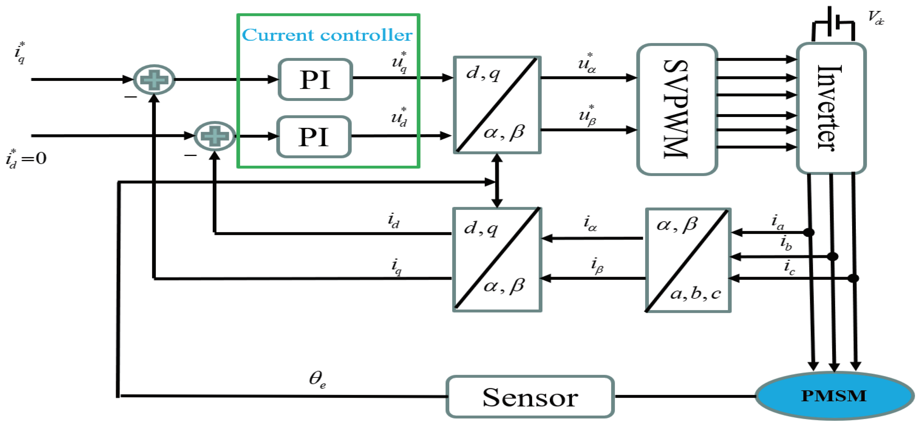
Figure 1 displays a detailed schematic of the sensor–encoder control intended for use with PMSM. In Figure 1, the components include coordinate transformation, SVPWM, and current control. The FOC strategy applied here converts the three-phase alternating current into a two-phase direct current. Consequently, by employing the FOC strategy, the control of a three-phase alternating current motor can be achieved similarly to that of a direct current motor. The discrepancies in the currents are fed into the proportional–integral (PI) regulators, ensuring current stabilization and facilitating the creation of control inputs and To simplify the analysis, it is assumed that the three-phase PMSM is an idea motor and meets the following conditions:
- (a)
- Saturation of the motor core is neglected;
- (b)
- Eddy current and hysteresis losses in the motor are not taken into account;
- (c)
- The current in the motor is a symmetrical three-phase sinusoidal waveform.
Therefore, the coordinate representing the dynamic current of the PMSM is expressed as follows [23,24]:
where , and are the resistance of the motor, number of pole pairs, motor speed, and permanent magnet flux linkage, respectively; and and denote the stator inductances on the axis, while and represent the stator voltages in the frame. The output equations of PI for the d-axis and q-axis are, respectively, given as follows:
where and . In Figure 1, there are 3 coordinate transformations: Clarke transformation, Park transformation, and inverse Park transformation. The formulas for the 3-coordinate Clarke transformation are as follows:
Owing to the complexity of traditional space vector pulse width modulation (SVPWM), which affects the efficiency of code generation, herein, an SVPWM algorithm using a third harmonic injection method is employed to generate saddle waves [25]. In this case, the SVPWM waveform is generated by injecting a third-order triangular harmonic into sinusoidal pulse width modulation (SPWM). To obtain the SVPWM voltage, starting with , the Clarke inverse transformation is used to derive the three-phase voltage of SPWM, after which a third-order triangular harmonic voltage is injected. After this processing step, the comparison values for the three-phase output can be directly computed. The corresponding formula is as follows:
The angle of coordinate transformation is obtained through the encoder.
2.2. Sensorless Control
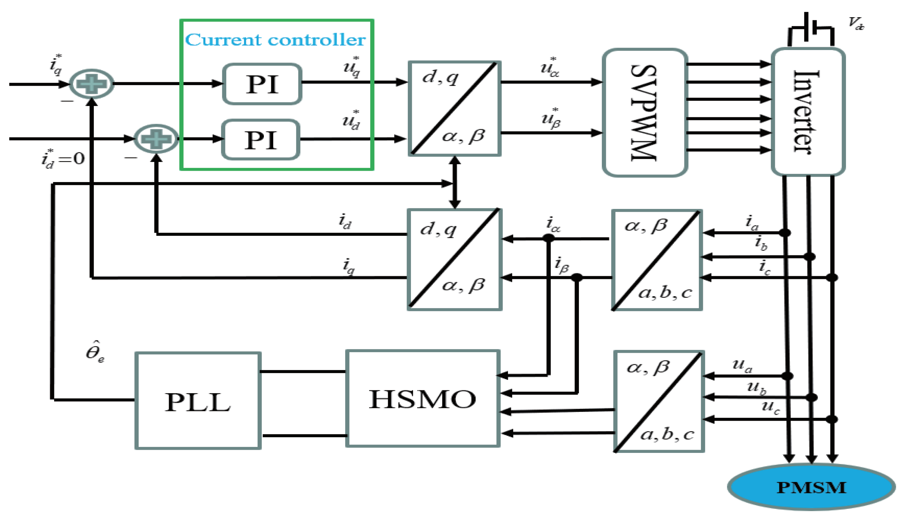
The diagram for sensorless control is shown in Figure 2. In Figure 2, the FOC strategy is still utilized, incorporating SVPWM and coordinate transformation. The only difference between Figure 1 and Figure 2 is the method of obtaining the electrical angle, . In Figure 2, the electrical angle is determined through the use of a high-order sliding mode observer (HSMO) combined with a phase-locked loop (PLL). The HSMO plays a crucial role in accurately estimating the electrical angle, while the PLL assists in synchronizing the estimated angle with the system’s reference signal. This combined technique offers improved performance and reliability in sensorless control systems, making it well-suited for a wide range of applications in various industries, including motor drives, renewable energy systems, and industrial automation. The formula for the HSMO is as follows [26]:
Given that the error dynamics (9) represent a time-varying system, it is noteworthy that the mechanical time constant is significantly larger than the electrical time constant. Consequently, it suggests that setting is appropriate. Therefore, the error dynamics of extended electromotive forces (EMFs) can be treated as a time-invariant system. This insight is crucial for simplifying the analysis and design of control strategies, as it allows for the application of techniques suitable for time-invariant systems, potentially leading to more efficient and practical control solutions. Because = 0 within a control cycle, Equation (10) is derived as follows:
Therefore, based on Equations (8) and (11), the high-order state equation with , , , as state variables is formulated as follows:
By selecting the sliding mode surface on the , plane, the high-order sliding mode observer constructed according to Equation (12) is as follows:
After estimating the values of back electromotive force and , PLL (see Figure 3) is required to extract angle . The formula for extracting the electrical angle using PLL is as follows:
As shown in Figure 3, after calculating , angular velocity can be calculated through PI control, and electrical angle can be obtained after one integration.
Remark 1.
In Figure 3, the phase-locked loop structure differs from a conventional phase-locked loop by incorporating the signum function. The purpose of introducing the signum function is to evaluate the angular velocity, thereby determining the direction of rotation of the motor.
Remark 2.
The incorporation of sign determination for angular velocity is only applicable to the EMF phase-locked loop. For the flux linkage phase-locked loop, additional judgments are unnecessary regardless of forward or reverse rotation, as the flux linkage always resides at the d-axis position and does not change direction with the rotation direction.
3. Flow Chart for Code Generation via Simulink
Figure 4 is the control flow diagram generated by the code. The application layer, based on MBD, can directly generate C-language code. The host is used for controlling motor startup, debugging, and data collection. In Figure 4, the low-level code is manually configured, including components such as an ADC (analog-to-digital converter), timers, and serial ports. ADC, timers, and serial ports are key interfaces in the REP. The middle layer serves as a bridge connecting the application layer and the low level. Only a minimal amount of code is required to connect the input and output interfaces. This manual configuration of low-level code defines our approach as semi-automatic code generation or model-based design (Semi-MBD). Eventually, all code is compiled in an integrated development environment (IDE), Keil v5, before being uploaded to the control board.
3.1. Sensor–Encoder Design
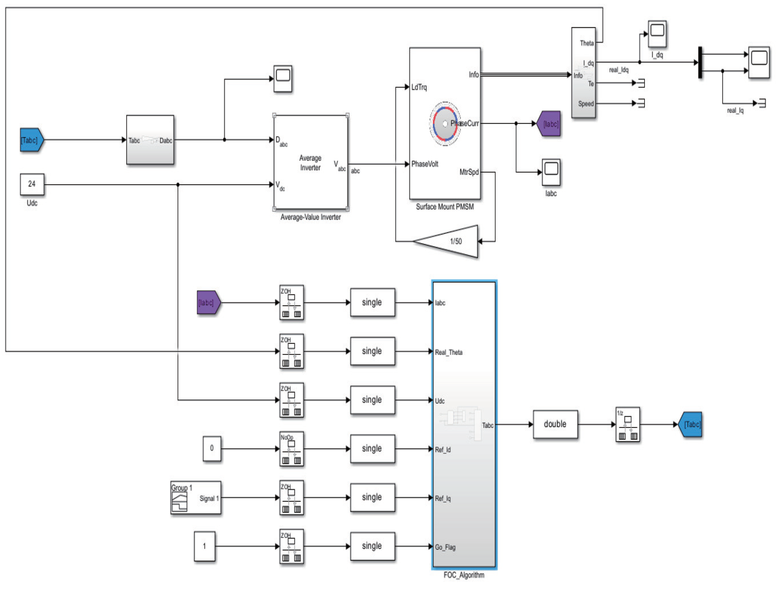
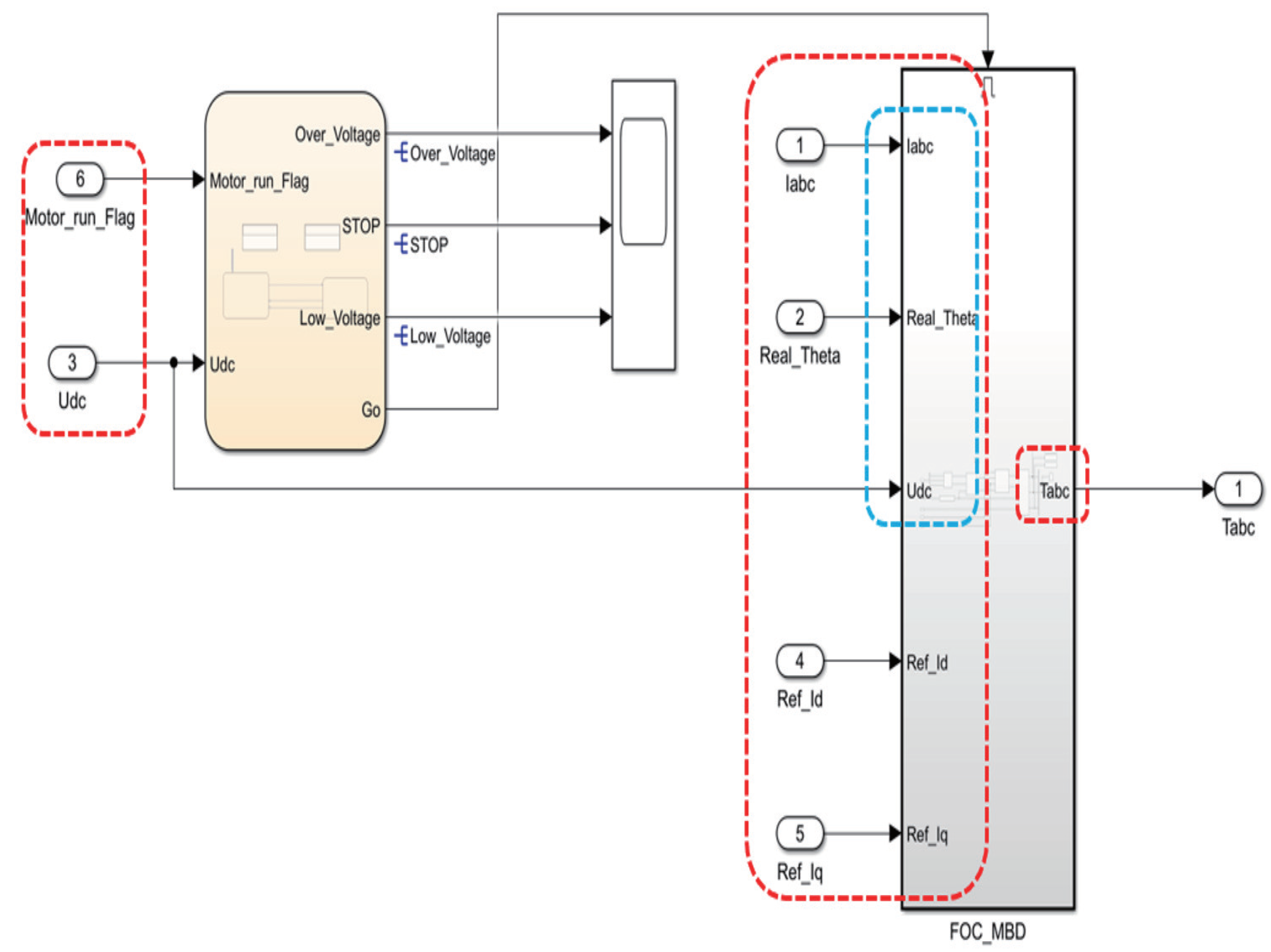
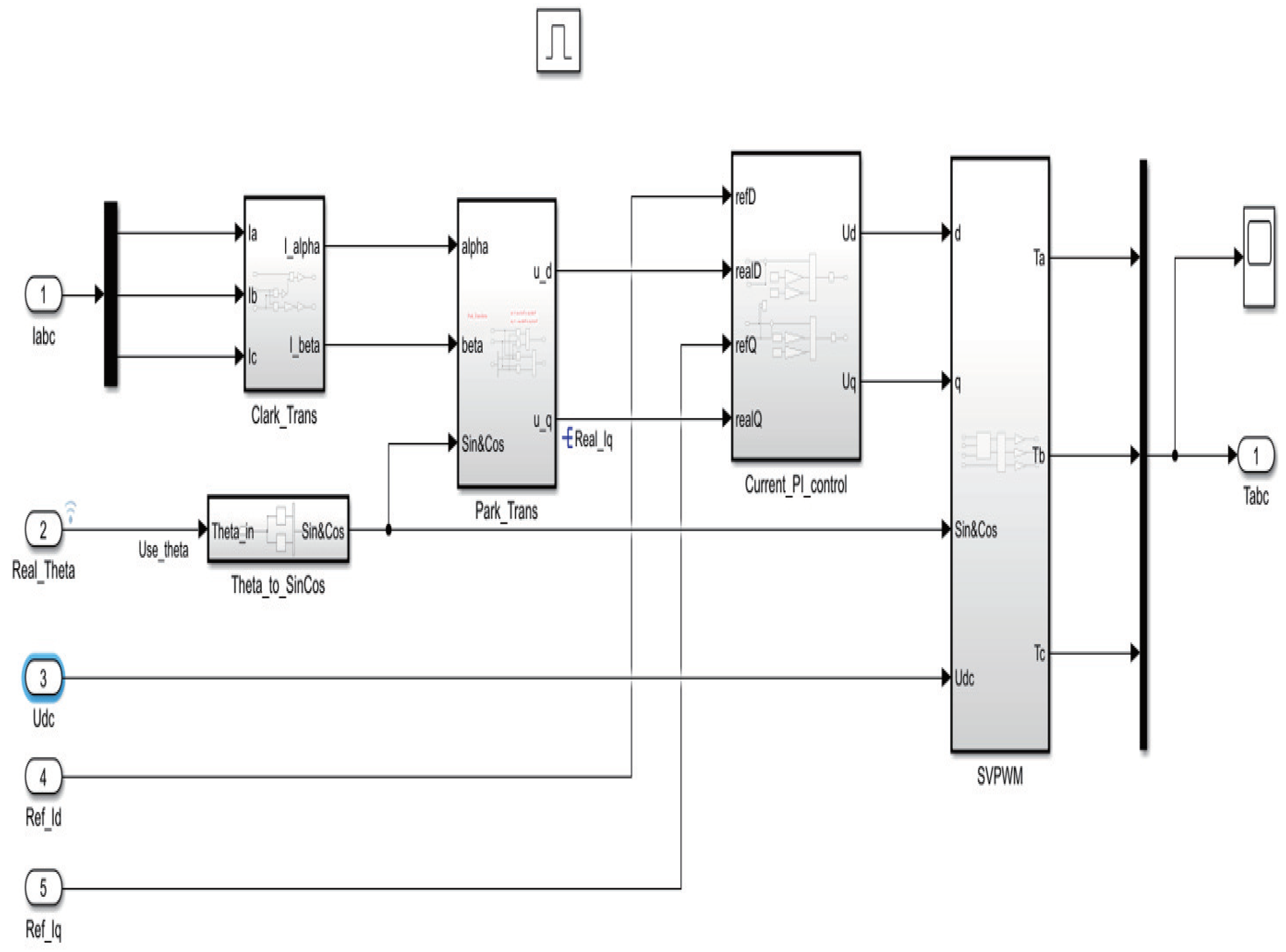
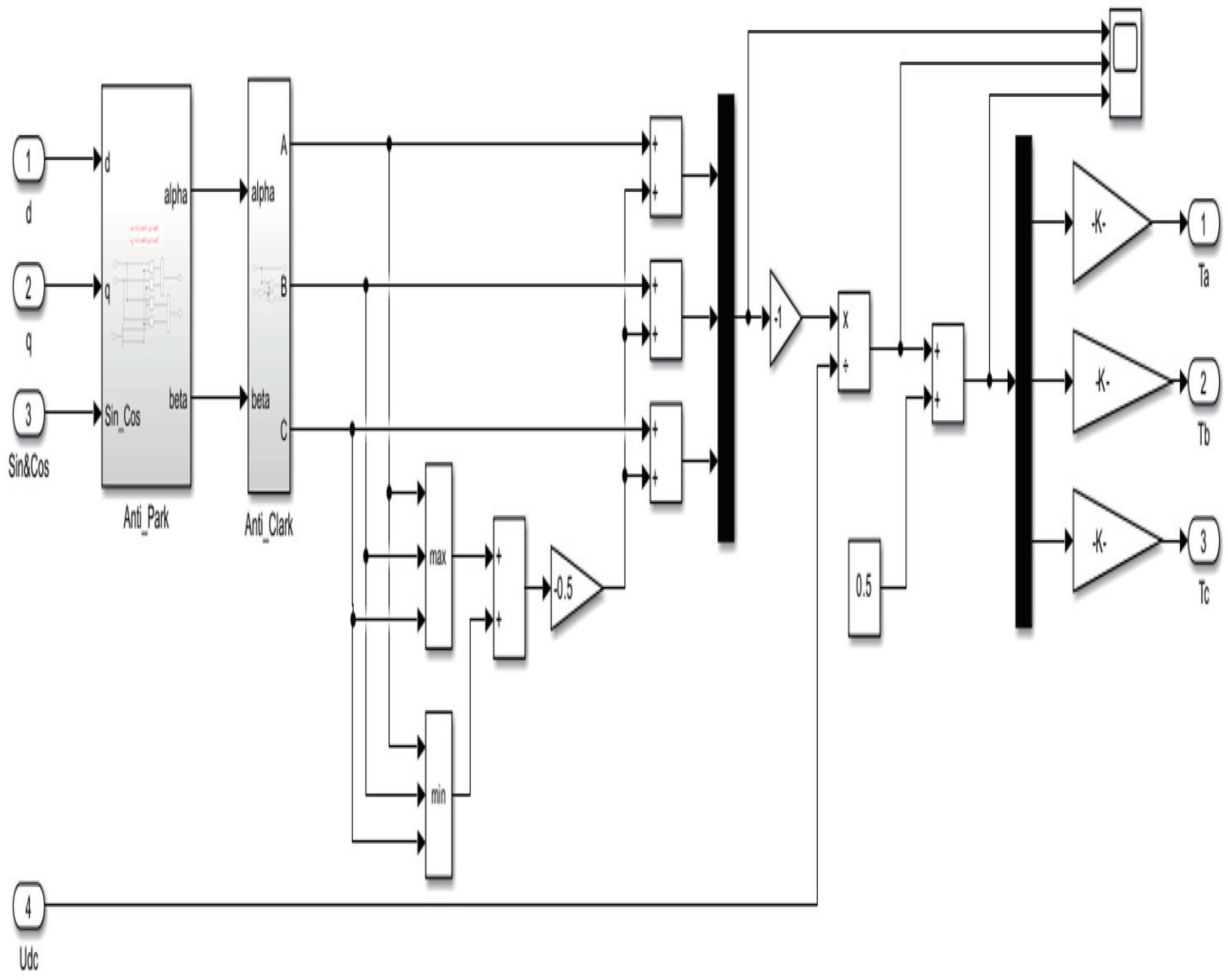
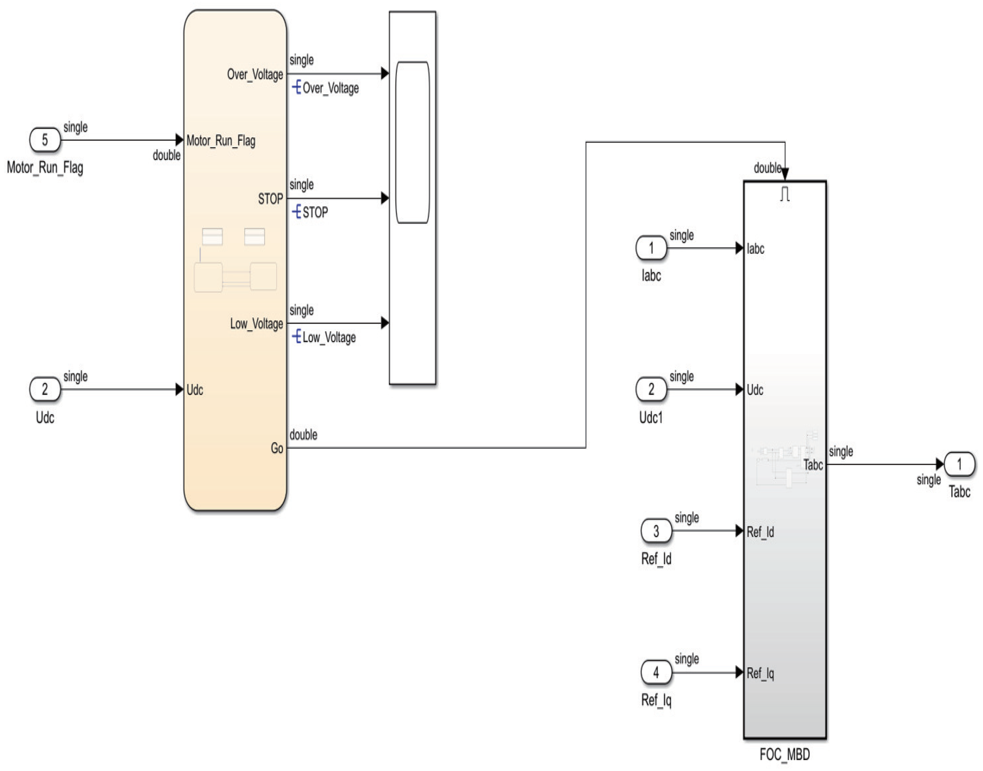
Figure 5 presents a diagram of the Simulink model for sensor-based control. This Simulink model is capable of not only performing simulations but also generating code for the application layer. Simulink, a MATLAB-based software, offers a graphical programming environment for modeling, simulating, and analyzing multi-domain dynamic systems. Its ability to generate code is particularly useful in streamlining the process of translating a simulated model into real-world applications, especially in complex control systems used in motor control. The Simulink model within the ‘FOC_Algorithm’ is shown in Figure 6. The ‘FOC_Algorithm’ consists of two parts: ‘Chart’ and ‘FOC_MBD’. The chart is used for controlling startup and bus voltage protection. ‘FOC_MBD’ is utilized for generating the application layer code. As shown in Figure 6, a total of five inputs is introduced into ‘FOC_MBD’, namely IABC, Real_Theta, Udc, Ref_Id, and Ref_Iq. Among these, IABC and Udc are obtained through ADC acquisition, Real_Theta is acquired via an encoder, while Ref_Id is typically set to zero, and Ref_Iq is a reference input obtained from a supervisory computer. Additionally, the output of ‘FOC_MBD’ is Tabc, for which the waveform is a saddle wave that is used in conjunction with timers to generate PWM (pulse width modulator) signals. The internal components of ‘Chart’ and ‘FOC_MBD’ are shown in Figure 7 and Figure 8, respectively.
3.2. Design of Sensorless Control
Figure 10 and Figure 11 present the Simulink diagram for the sensorless control system. Compared to that of the sensor-based system shown in Figure 5 and Figure 6, the angle in this sensorless setup is not acquired from an encoder but is instead estimated using a combination of HSMO and PLL. Figure 12 shows the model for obtaining the angle in the sensorless system, where the electrical angle is estimated through HSMO combined with PLL. The construction of this model is based on Equation (14) and Figure 3.
Remark 3.
Apart from the difference in the method of obtaining angle , the other parts of the system are almost identical, with the exception of the gain settings in the PI controllers.
Remark 4.
As shown in Figure 5 and Figure 10, a data type conversion module is utilized. This module converts all external input data into the ‘single’ data type to ensure that the generated code is entirely of the ‘float’ type. Additionally, the use of a ‘double’ conversion module converts the ‘single’ type outputs back to ‘double’. This ensures proper execution of the simulations. The purpose of these conversions is to align the data types used in the simulation with those in the real-world application, facilitating a seamless transition from the model to the actual implementation.
Remark 5.
To adhere to the Shannon sampling theorem, a ‘Rate Transition’ module is used. This module sets the execution frequency of the FOC algorithm to 10 kHz, while the frequency for the rest of the modules is set to 20 kHz. As this approach ensures that the sampling rate is sufficient to accurately capture and reconstruct the signal, a fundamental principle is derived from the Shannon sampling theorem, which states that the sampling rate must be at least twice the highest frequency present in the signal to accurately represent it without aliasing. By setting different frequencies for the FOC algorithm and other modules, the system effectively balances the performance and computational load.
4. Simulation Results
This section presents the simulation results. The parameters of the PMSM are listed in Table 1. The parameters used in the simulation are detailed in Table 2 and Table 3, including those for both sensor-based and sensorless control.
4.1. Sensor–Encoder Simulation Results
Figure 13, Figure 14 and Figure 15, respectively, show the d-axis current tracking waveform with the sensor, the q-axis current tracking waveform, and the saddle wave waveform. Figure 13 and Figure 14 demonstrate effective tracking performance, thus validating the feasibility of the simulation results. From Figure 13, it is evident that with the strategy where , the value remains consistently at zero. Additionally, as shown in Figure 14, the current is effectively tracked against the desired current. Figure 15 simultaneously presents a distinct saddle wave, where the variations depicted are due to changes in the current.
4.2. Simulation Results Using Sensorless Control
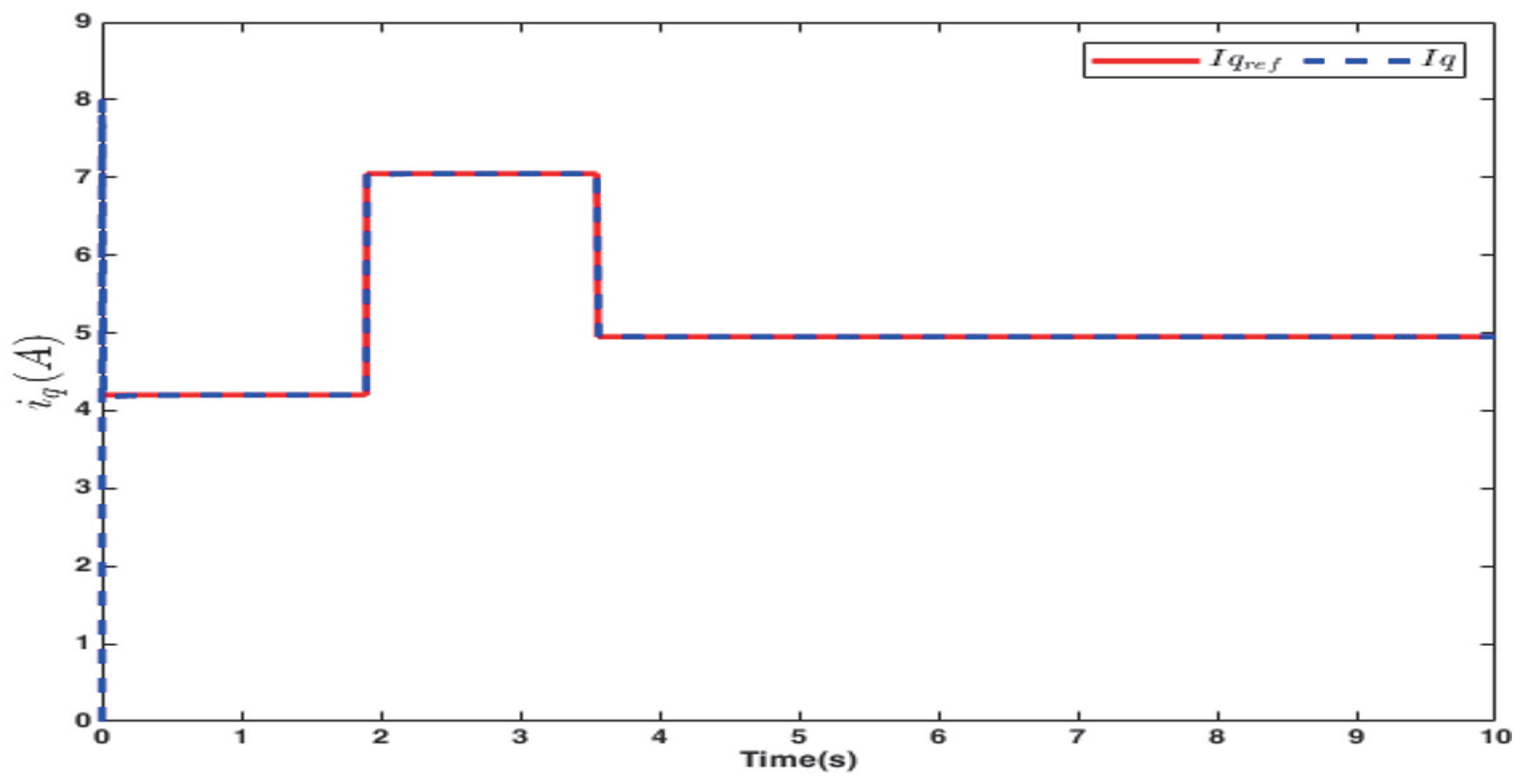
Figure 16, Figure 17 and Figure 18, respectively, illustrate the d-axis current tracking waveform, the q-axis current tracking waveform, and the saddle wave waveform for the sensorless case. Figure 16 and Figure 17 demonstrate effective tracking performance, thereby confirming that the simulation outcomes are reasonable. Figure 16 reveals that, compared to Figure 13, there are fluctuations in the current, though they are relatively minor. This is attributed to the requirement for electrical angle estimation in sensorless control, which directly influences the angle used in coordinate transformations. The minor nature of these fluctuations is considered acceptable within the context of sensorless control. Furthermore, to demonstrate the efficacy of tracking in sensorless control, Figure 17 sets the desired to vary significantly. Moreover, Figure 18 displays an exemplary saddle wave form.
5. Results of Experiment
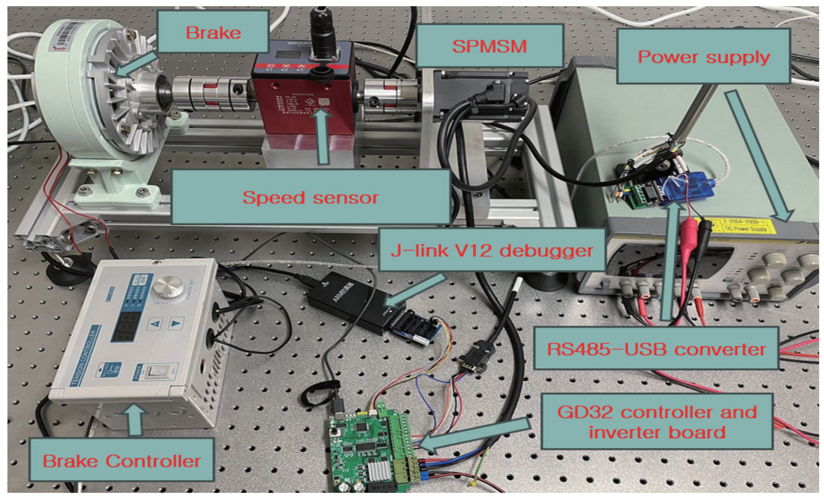
A PMSM driven by a PWM inverter connected to a three-phase voltage source was developed. This inverter operates at a switching frequency of 10 kHz. To introduce load disturbances, a current brake is employed to modulate the output torque of the eddy current brake by varying the excitation current. The control algorithms discussed in this study were implemented in a GD32F407RET6 microcontroller (GigaDevice, Beijing, China), which operates at a clock frequency of 168 MHz. These programs were developed using Keil IDE version 5.36 and were subsequently transferred to the microcontroller via a J-link debugger (version 12). The experimental data were collected using a speed sensor. The configuration of the experimental hardware is illustrated in Figure 19.
To facilitate the integration of the code generated by the model with the IDE for use, the method of connection was outlined, as demonstrated in Figure 6 and Figure 11. For closed-loop simulation, inputs such as three-phase current and bus voltage are required, while the output should generate a saddle waveform to produce six PWM signals. Consequently, the interfaces used in the experiments based on the REP approach were consistent with those depicted in the figures. The three-phase current and bus voltage were collected through the chip’s ADC module, and the saddle waveform was connected to the timer’s register. This approach is applicable to both sensor-based and sensorless control systems; the primary distinction between them lies in whether a sensor is utilized to obtain the angle.
Remark 6.
To demonstrate the feasibility and efficiency of the REP, the parameters for both experiments and simulations were kept consistent, as shown in Table 2.
Remark 7.
The limitation of REP is that it does not have fully automatic code generation. Although it does not have the feature of fully automatic code generation, only a small amount of code is required in REP to complete the connection between the bottom layer and the application layer.
5.1. Results of Sensor–Encoder Experiment
The outcomes of sensor-controlled operations with the encoder are depicted in Figure 20, Figure 21 and Figure 22, which show, respectively, the results for the d-axis current, the q-axis current, and the three-phase current. The figures demonstrate effective control outcomes, validating the feasibility of the REP. These three images are based on the REP scheme for sensor-based control, where the parameters of the controller used are consistent with those in the simulations. In Figure 20, it can be observed that the value remains minimal, fluctuating within the range of ±0.2 during the actual process, exhibiting only minor spikes in the signal when the current changes. In Figure 22, the variation in the three-phase current is smooth, and as current decreases, the actual three-phase current also diminishes.
5.2. Results of Sensorless Control Experiment
The results with sensorless control are presented in Figure 23, Figure 24 and Figure 25, which illustrate, respectively, the outcomes for the d-axis current, the q-axis current, and the three-phase current. The figures show favorable control results, affirming the feasibility of the REP. The outcomes of sensorless control exhibit slightly more fluctuation compared to those of sensor-based control, but are viable for sensorless control applications. In sensorless control, the current ripple is larger compared to sensor-based control, which is deemed reasonable and feasible. This is because, in sensorless control, it is necessary to estimate the electrical angle which directly affects the current. However, as observed in the three-phase current from Figure 25, although there are fluctuations in the current ripple, they remain within the range of ±1 A. To validate the effectiveness of the REP approach, the parameters here are kept consistent with those used in the sensorless simulations.
6. Discussion
This study presents the design of a code generator for REP based on a model approach. By utilizing REP, users can swiftly set up simulations and experiments, thereby accelerating the development of control strategies. Additionally, because REP does not rely on complex toolboxes and solely utilizes basic Simulink models and Simulink-to-C language tools, the generated code exhibits commendable portability. The feasibility of REP is confirmed by demonstrating the progression from model-based and sensorless control to simulation, and from simulation to experimental validation. Through REP, simulations can be performed first, and desired simulation results can be obtained in advance of experiments which can avoid safety hazards and property losses caused by direct experiments. Product development can therefore be accelerated. At the same time, REP is a solution based on MBD and can handle complex electromechanical systems well.
Author Contributions
All the authors contributed to this paper. M.H. and K.Y. conceived the idea, performed the analysis, and designed the simulation; M.H. and Y.C. carried out the numerical simulations; H.A., H.K., Y.C. and K.Y. co-wrote the manuscript. All authors have read and agreed to the published version of the manuscript.
Funding
This work was supported by the National Research Foundation of Korea (NRF) grant funded by the Korea government (MSIP) (NRF-2019R1A2C1002343) and the BK21 FOUR Project.
Data Availability Statement
The raw data supporting the conclusions of this article will be made available by the authors on request.
Acknowledgments
During the preparation of this work the authors used ChatGPT in order to improve English editing. After using this tool, the authors reviewed and edited the content as needed and take full responsibility for the content of the publication.
Conflicts of Interest
The authors declare no conflicts of interest.
References
- Krizan, J.; Ertl, L.; Bradac, M.; Jasansky, M.; Andreev, A. Automatic code generation from Matlab/Simulink for critical applications. In Proceedings of the 2014 IEEE 27th Canadian Conference on Electrical and Computer Engineering (CCECE), Toronto, ON, Canada, 4–7 May 2014. [Google Scholar]
- Andrs, O.; Hadas, Z.; Kovar, J.; Vetiška, J.; Singule, V. Model-Based Design of Mobile Platform with Integrated Actuator–Design with Respect to Mechatronic Education. In Mechatronics 2013: Recent Technological and Scientific Advances; Springer: Cham, Switzerland, 2014; pp. 891–898. [Google Scholar]
- Su, Z.; Wang, D.; Yu, Z.; Yang, Y.; Jiang, Y.; Wang, R.; Chang, W.; Li, W.; Cui, A.; Sun, J. PHCG: Optimizing Simulink Code Generation for Embedded System With SIMD Instructions. IEEE Trans. Comput.-Aided Des. Integr. Circuits Syst. 2023, 42, 1072–1084. [Google Scholar] [CrossRef]
- Hu, D.; Alsmadi, Y.M.; Xu, L. High-Fidelity Nonlinear IPM Modeling Based on Measured Stator Winding Flux Linkage. IEEE Trans. Ind. Appl. 2015, 51, 3012–3019. [Google Scholar] [CrossRef]
- Rademacher, F.; Sorgalla, J.; Sachweh, S.; Zündorf, A. A model-driven workflow for distributed microservice development. In Proceedings of the 34th ACM/SIGAPP Symposium on Applied Computing, Limassol, Cyprus, 8–12 April 2019. [Google Scholar]
- Bosso, A.; Tilli, A.; Conficoni, C. A Hybrid sensorless observer for the robust global asymptotic flux reconstruction of permanent magnet synchronous machines. IEEE Control Syst. Lett. 2022, 6, 3367–3372. [Google Scholar] [CrossRef]
- Chatri, C.; Labbadi, M.; Ouassaid, M.; Elyaalaoui, K.; Houm, Y.E. Design and implementation of finite-time control for speed tracking of permanent magnet synchronous mtors. IEEE Control Syst. Lett. 2023, 7, 721–726. [Google Scholar] [CrossRef]
- Chen, B.; Wang, K.; Le, Y. High-precision position error correction method for the PMSM based on low-order harmonic Suppression. IEEE Trans. Power Electron. 2021, 36, 4500–4512. [Google Scholar] [CrossRef]
- Chen, H.; Demerdash, N.A.O.; EL-Refaie, A.M.; Guo, Y.; Hua, W.; Lee, C.H.T. Investigation of a 3D-magnetic flux PMSM with high torque density for electric vehicles. IEEE Trans. Energy Convers. 2022, 37, 1442–1454. [Google Scholar] [CrossRef]
- Zhang, Z.; Liu, X.; Yu, J.; Yu, H. Time-varying disturbance oserver based improved sliding mode single-loop control of PMSM drives with a hybrid reaching law. IEEE Trans. Energy Convers. 2023, 38, 2539–2549. [Google Scholar] [CrossRef]
- Xu, B.; Zhang, L.; Ji, W. Improved non-singular fast terminal sliding mode control with disturbance observer for PMSM drives. IEEE Trans. Transp. Electrif. 2021, 7, 2753–2762. [Google Scholar] [CrossRef]
- Lee, J.; Lee, J.S. Rapid control prototyping for PMSM drives using DSPs and PLECS. In Proceedings of the 2021 24th International Conference on Electrical Machines and Systems (ICEMS), Gyeongiu, Republic of Korea, 31 October 31–3 November 2021. [Google Scholar]
- Saralegui, R.; Sanchez, A.; de Castro, A. Efficient hardware-in-the-loop models using automatic code generation with MATLAB/Simulink. Electronics 2023, 12, 2786. [Google Scholar] [CrossRef]
- Srivastava, A.; Padgil, R.; Gupta, A.; Lohia, A.; Nair, N.P. Model-based sensored field oriented control implementation for permanent magnet synchronous motor. In Proceedings of the 2021 International Symposium of Asian Control Association on Intelligent Robotics and Industrial Automation (IRIA), Goa, India, 20–22 September 2021. [Google Scholar]
- Jin, X.; Zhang, T.; Zhang, H.; Zeng, P.; Wang, A. Research on servo system of permanent magnet synchronous motor based on model design. In Proceedings of the 2018 International Conference on Advanced Control, Automation and Artificial Intelligence (ACAAI 2018), Shenzhen, China, 21–22 January 2018. [Google Scholar]
- Belhamel, L.; Buscarino, A.; Cucuccio, A.; Fortuna, L.; Rascona, G. Model-based design streamlines for STM32 motor control embedded software system. In Proceedings of the 2020 7th International Conference on Control, Decision and Information Technologies (CoDIT), Prague, Czech Republic, 29 June–2 July 2020. [Google Scholar]
- Wild, L.; Incurvati, M.; Schiestl, M.; Staerz, R. Rapid prototyping framework for integrated modular motor drives: Modelling, simulation and automated code generation. In Proceedings of the PCIM Europe 2022; International Exhibition and Conference for Power Electronics, Intelligent Motion, Renewable Energy and Energy Management, Nuremberg, Germany, 10–12 May 2022; pp. 1–10. [Google Scholar]
- Zhao, G.; Zhang, S. Development of permanent magnet synchronous motor RCP based on hardware-in-the-loop simulation. In Proceedings of the 2018 IEEE International Conference on Mechatronics and Automation (ICMA), Changchun, China, 5–8 August 2018. [Google Scholar]
- Jiang, W.; Han, W.; Wang, L.; Liu, Z.; Du, W. Linear golden section speed adaptive control of permanent magnet synchronous motor based on model Design. Processes 2022, 10, 1010. [Google Scholar] [CrossRef]
- Ma, Z.; Saeidi, S.; Kennel, R. FPGA implementation of model predictive control with constant switching frequency for PMSM drives. IEEE Trans. Ind. Inform. 2014, 10, 2055–2063. [Google Scholar] [CrossRef]
- Koga, T.; Abe, T.; Otomo, Y.; Yamamoto, M.; Rosu, M. Reduced order modeling of half-wave rectified brushless synchronous motor for model-based design. IEEJ J. Ind. Appl. 2023, 12, 826–834. [Google Scholar] [CrossRef]
- Liu, K.; Jiang, D.; Sun, W.; Liu, Z. A motor controller development framework based on switch model simulation and all code automatic generation. In Proceedings of the 2019 22nd International Conference on Electrical Machines and Systems (ICEMS), Harbin, China, 11–14 August 2019. [Google Scholar]
- Sun, X.; Yu, H.; Yu, J.; Liu, X. Design and implementation of a novel adaptive backstepping control scheme for a PMSM with unknown load torque. IET Electr. Power Appl. 2019, 13, 445–455. [Google Scholar] [CrossRef]
- Petrovic, V.; Ortega, R.; Stankovi, A. Interconnection and damping assignment approach to control of PM synchronous motors. IEEE Trans. Control Syst. Technol. 2001, 9, 811–820. [Google Scholar] [CrossRef]
- Zhou, K.; Wang, D. Relationship between space-vector modulation and three-phase carrier-based PWM: A comprehensive analysis [three-phase inverters]. IEEE Trans. Ind. Electron. 2002, 49, 186–196. [Google Scholar] [CrossRef]
- Wang, G.; Li, Z.; Zhang, G.; Yu, Y.; Xu, D. Quadrature PLL-based high-order sliding-mode observer for IPMSM sensorless control with online MTPA control strategy. IEEE Trans. Energy Convers. 2013, 28, 214–224. [Google Scholar] [CrossRef]
Figure 1.
Diagram of a sensor-based control system for PMSM.

Figure 2.
Diagram of a sensorless control system for PMSM.

Figure 3.
Diagram of phase-locked loop structure.

Figure 4.
Flowchart of rapid control prototyping structure using MBD.

Figure 5.
Diagram of a sensor-equipped Simulink model.

Figure 6.
Diagram of internal Simulink model for FOC_ Algorithm for sensor–encoder control design.

Figure 7.
Diagram of internal Simulink model for ‘Chart’.

Figure 8.
Diagram of internal Simulink model for FOC_MBD.

Figure 9.
Diagram of internal Simulink model for SVPWM.

Figure 10.
Diagram of sensorless Simulink model.

Figure 11.
Diagram of internal Simulink model for FOC_ Algorithm for sensorless control desgin.

Figure 12.
Diagram of high-order sliding mode observer model.

Figure 13.
d-axis current with sensor in simulation.

Figure 14.
q-axis current with sensor in simulation.

Figure 15.
Saddle waveform for generating PWM with sensor in simulation.

Figure 16.
d-axis current without sensor in simulation.

Figure 17.
q-axis current without sensor in simulation.

Figure 18.
Saddle waveform for generating PWM without sensor in simulation.

Figure 19.
Experimental object platform.

Figure 20.
d-axis current with sensor in experiment.

Figure 21.
q-axis current with sensor in experiment.

Figure 22.
3-phase current with sensor in experiment.

Figure 23.
d-axis current without sensor in experiment.

Figure 24.
q-axis current without sensor in experiment.

Figure 25.
3-phase current without sensor in experiment.


Table 1.
Parameter values of the PMSM.
| Parameters | Value | Unit |
|---|---|---|
| Resistance | 0.05 | |
| Inductance | ||
| Flux linkage | 0.0065 | |
| Inertia J | ||
| Damping coefficient | ||
| Pole pairs | 5 |
Table 2.
Parameter values of the controller for the sensor case.
| Parameters | Value |
|---|---|
| 0.1470 | |
| 75 | |
| 0.1470 | |
| 75 |
Table 3.
Parameter values of the controller for the sensorless case.
| Parameters | Value |
|---|---|
| 0.1470 | |
| 75 | |
| 0.1470 | |
| 75 | |
| k | 1 |
| m | 0.17 |
| 5 | |
| 50 |
Disclaimer/Publisher’s Note: The statements, opinions and data contained in all publications are solely those of the individual author(s) and contributor(s) and not of MDPI and/or the editor(s). MDPI and/or the editor(s) disclaim responsibility for any injury to people or property resulting from any ideas, methods, instructions or products referred to in the content. |
© 2024 by the authors. Licensee MDPI, Basel, Switzerland. This article is an open access article distributed under the terms and conditions of the Creative Commons Attribution (CC BY) license (https://creativecommons.org/licenses/by/4.0/).
Share and Cite
MDPI and ACS Style
Hu, M.; Ahn, H.; Kang, H.; Chung, Y.; You, K. Rapid Experimental Protocol for PMSM via MBD: Modeling, Simulation, and Experiment. Computers 2024, 13, 73. https://0-doi-org.brum.beds.ac.uk/10.3390/computers13030073
AMA Style
Hu M, Ahn H, Kang H, Chung Y, You K. Rapid Experimental Protocol for PMSM via MBD: Modeling, Simulation, and Experiment. Computers. 2024; 13(3):73. https://0-doi-org.brum.beds.ac.uk/10.3390/computers13030073
Chicago/Turabian StyleHu, Mingyuan, Hyeongki Ahn, Hyein Kang, Yoonuh Chung, and Kwanho You. 2024. "Rapid Experimental Protocol for PMSM via MBD: Modeling, Simulation, and Experiment" Computers 13, no. 3: 73. https://0-doi-org.brum.beds.ac.uk/10.3390/computers13030073
Note that from the first issue of 2016, this journal uses article numbers instead of page numbers. See further details here.