Enhanced Shadow Retargeting with Light-Source Estimation Using Flat Fresnel Lenses
by

Llogari Casas Cambra
1,*, 
Matthias Fauconneau
1,
Maggie Kosek
2,
Kieran Mclister
3 and
Kenny Mitchell
1 1
School of Computing, Edinburgh Napier University, Edinburgh EH10 5DT, UK
2
Centre for Vision, Speech and Signal Processing, University of Surrey, Guildford GU2 7XH, UK
3
Edinburgh College of Art, University of Edinburgh, Edinburgh EH3 9DF, UK
*
Author to whom correspondence should be addressed.
†
This paper is an extended version of our paper: Casas, L.; Fauconneau, M.; Kosek, M.; Mclister, K.; Mitchell, K. Image Based Proximate Shadow Retargeting. In Proceedings of the Computer Graphics & Visual Computing (CGVC) 2018, Wales, UK, 13–14 September 2018.
Computers 2019, 8(2), 29; https://0-doi-org.brum.beds.ac.uk/10.3390/computers8020029
Submission received: 29 January 2019
/
Revised: 22 March 2019
/
Accepted: 26 March 2019
/
Published: 2 April 2019
(This article belongs to the Special Issue Selected Papers from the Computer Graphics & Visual Computing (CGVC 2018))
Abstract
:Shadow-retargeting maps depict the appearance of real shadows to virtual shadows given corresponding deformation of scene geometry, such that appearance is seamlessly maintained. By performing virtual shadow reconstruction from unoccluded real-shadow samples observed in the camera frame, this method efficiently recovers deformed shadow appearance. In this manuscript, we introduce a light-estimation approach that enables light-source detection using flat Fresnel lenses that allow this method to work without a set of pre-established conditions. We extend the adeptness of this approach by handling scenarios with multiple receiver surfaces and a non-grounded occluder with high accuracy. Results are presented on a range of objects, deformations, and illumination conditions in real-time Augmented Reality (AR) on a mobile device. We demonstrate the practical application of the method in generating otherwise laborious in-betweening frames for 3D printed stop-motion animation.
1. Introduction
Producing visually realistic compositions at interactive rates in Augmented Reality (AR) is becoming of increasing importance in both research and commercial applications. It requires relighting techniques to achieve plausible integrations between virtual objects and real-world scenes. Such reality mixing, when done in mobile computing, becomes specifically challenging due to the limited amount of available resources. Nonetheless, this seamless integration between virtuality and reality is becoming more achievable due to the recent advances in high-performance mobile computing. Such cutting-edge algorithms achieve enhanced real-time capabilities for Mixed Reality (MR) applications in commercial mobile devices. This trend enables our goal to combine the virtual and physical worlds seamlessly together and create a convincing illusion of movement for normally static and inanimate objects.
Retargeting-reality techniques, such as shadow-retargeting [1] have succeeded in animating scene content while retaining the importance and visual consistency of features from real-world objects. This technique adapts image-based rendering concepts to create the illusion of realistic movement for static objects that have previously been scanned or 3D-printed. It focuses on retargeting the appearance of shadows when virtually deforming physical objects in real time. The algorithm maps the real shadow to the projected virtual shadow’s footprint with an importance guided search according to physically modelled shadow behaviour. This forms the weighted reference for appearance sampling when performing the reconstruction of the deformed shadow. In this manuscript, we extend this work to allow the method to work without a set of pre-established conditions. We highlight the main contributions as follows:
- in order to allow shadow retargeting to work without a set of pre-established conditions, we introduce a novel light-estimation approach employing a flat light probe fabricated using a flat reflective Fresnel lens. Unlike three-dimensional sampling probes, such as reflective spheres, Fresnel lenses can be incorporated into any type of quotidian object, such as a book or product packaging, providing a seamless light-estimation approach for AR experiences.
- given that this algorithm demonstrates practical applications in generating in-betweening frames for 3D-printed stop-motion animation, we enhanced the capabilities of the algorithm to supply the needs of the animators by handling light sources casting shadows over multiple-receiver surfaces.
- with the aim of easing the practical application of the algorithm, we extended the adeptness of the approach by handling shadows cast by an occluder lifted from the ground plane.
2. Related Work
Shadow retargeting relates to a variety of research areas in Augmented Reality to overlay a photorealistic augmentation. Section 2.1 details how this methods draws from image-retargeting techniques to animate physical puppets. Section 2.2 describes how the method relates to context-aware fill algorithms to reconstruct the retargeted shadow and the revealed background. Section 2.3 evaluates scene-relighting techniques, and how these differ from estimating light sources using quotidian objects. Section 2.4 highlights the uniqueness of the method compared to other shading techniques in augmented reality.
2.1. Retargeting Reality
Image retargeting, also known as content-aware resizing, aims to retarget an image to a form with visual constraints (e.g., size) while preserving its main features. Maintaining an aesthetically plausible output when performing deformations on an image can be a challenging problem to address. Approaches from Setlur et al. [2] and Goferman et al. [3] used content-aware importance maps and regions of interest to perceptually guide and steer image sampling in the retargeted reconstruction. Here, we applied the concept of image retargeting to AR, in the case where we knew the segmented 3D geometry of physical objects in the image and the ability to register the mesh pose in real time with markerless 3D object tracking [4] (using Vuforia [5]).
AR image-retargeting approaches are relatively novel and the first method, introduced in 2011 by Leao et al. [6], is a relatively isolated work. Prior to this, virtual objects have been typically overlaid into the physical space as an independent entity or through re-rendering with elaborate light estimation using a visible chrome sphere by Nowrouzezahrai et al. [7]. Altered reality [6] provides a method in which a homogeneous mesh is projected on top of its physical counterpart; a simple deformed cube in this first instance. This demonstration was limited, as it neither addressed relighting through the direct employed cube transformation nor did the approach addressing shadows as indirect relighting. Additionally, real-time performance was limited to high-end desktop PCs. In contrast, our method introduces direct and indirect relighting on mobile devices in real time.
In 2012, Clayvision introduced a related scheme for building scale objects in the city. This method prescanned a set of known locations into reconstructed meshes. The live camera feed was patched with a premodified version of the background image in which the appropriate building was previously removed and manually inpainted. Upon the movement of the building’s virtual animated mesh, the desired deformed pixels were overlaid on the camera image [8]. While this achieved real-time performance in mobile devices, it did not address any means of indirect relighting.
Real-time texture retargeting from a camera feed was achieved through the conversion of 2D hand-painted drawings to a 3D colored mesh by Magnenat et al. [9]. In this approach, a static lookup map was built in order to match every pixel of the drawing to corresponding sample locations on the mesh. Our method extends this with a dynamic texture lookup according to the overlaid animation over time for the purpose of shadow retargeting.
Props Alive introduced a flexible method for object-appearance retargeting using texture deformation from a live video stream [10]. This approach allows for plausible photorealistic augmented-reality appearance, since the material, illumination, and shading of the object are updated to the virtual mesh in each frame. Following the foundations of this approach, shadow retargeting was introduced [1]. This method directly synthesises virtual shadows by sampling the image that contains the shadow of the toy presented in the real world. In this study, we enhance the capabilities of this algorithm by handling camera movements, and demonstrate the accuracy of the approach by presenting additional results in more complex settings.
2.2. Image Inpainting
As defined in the Severely Mediated Virtuality Continuum [11], in an ideal mixed-reality environment, the user should be able to add and subtract visual content on an equal basis. Image inpainting, also known as context-aware fill or diminished reality (when done in real-time), aims to subtract information from a live camera feed achieving plausible results.
Scene reconstruction with structural and perceptual consistency has demonstrated to be computationally expensive over time [12,13]. In 2012, PixMix achieved inpainting in real time with few background constraints and without the need of a multiview approach [14]. This algorithm iteratively minimizes a spatial and appearance cost function, with the consistency of neighbouring pixels and patterned backgrounds. Nevertheless, online performance was still limited to high-end processors in personal computers.
A related case for shadow inpainting was introduced by Zhang et al. [15], in which an illumination-recovering optimization method is used for shadow removal. However, our approach focuses on reconstructing it for another pose instead.
In the case of mobile devices, methods often require additional information, such as using multiple handheld devices [16], or mapping textured background planes [17]. Indeed, Clayvision [8] was configured to remove original in a set of pre-established locations. Shadow retargeting uses a background-observation method [18] similar to [8], in which the user captures the background of the scene before initialising our method.
2.3. Scene Relighting
Knecht et al., through the study of photorealistic augmented reality, presented visual cues as key elements for human perception [19]. It concluded that, if one wants to accomplish a photorealistic appearance, virtual meshes need to be adequately relighted according to the real-world scene. This need introduces what is known as the relighting problem, in which an already illuminated virtual mesh needs to be correctly shaded according to real-world light sources. To do so, light probes from preknown locations, objects, or references are normally employed [20,21].
Early examples used environmental maps to efficiently relight a 3D model according to its environment [22]. This early method used nine coefficient models for calculating its low-frequency spherical harmonic representations. A quadratic polynomial equation was employed to shade virtual meshes according to their surroundings. Subsequently, this technique was extended using precomputed radiance functions [23]. This enabled real-time relighting using environment maps under preset conditions [24].
Further techniques included differential photon mapping to calculate lighting variance in the scenario [25]. Using this technique, virtual objects were relighted according to the shading difference between the real and augmented scene. This was further extended using light fields [26]. This addition enabled consistent augmentation of virtual objects with both direct and indirect lighting. When combined with instant radiosity, a plausible replica of the real-world environment can be computed in mixed reality [27].
More recent results approached light estimation with real-world scene helpers. These are predefined artefacts used for reflectance estimation. The usage of a chrome sphere can extract distant light sources from the surface normal of a reflective point over a perfect sphere [28]. A 3D-printed shading probe can be used to capture both hard and soft shadow behaviour from general illumination environments [20]. Human faces can be used as light probes for coherent rendering of virtual content [29]. Depth maps can provide supplementary information to reconstruct light-source positions in a scene recorded by an RGB-D camera [30]. Convolutional Neural Networks (CNNs) enabled a related scheme for relighting using every-day objects [31]. This method used learned light probes over a pre-established object to detect environment lighting. Nonetheless, this technique requires to previously train a CNN with all possible types of lighting of an object, and to extract and store spherical harmonics for each view.
In this study, we introduce a light-estimation approach that enables light-source detection using flat Fresnel lenses embedded in every-day objects. Drawing from a reflective-chrome-sphere method [28], we estimated light-source positions through a 180 degree planar Fresnel film. We embedded this reflector in detectable objects, enabling light-source estimation in mobile devices without additional gadgets.
2.4. Augmented-Reality Shadows
An early offline method used observed shadow brightness to recover the illumination of the scene [32]. Real-time shadow volumes were prepared manually in [33] to demonstrate the various configurations of virtual- and real-shadow caster and receiver interactions, but did not address the shadow overlap. Jacobs et al. [34] addressed the shadow overlap, but did not consider more than one light source or the general light environment. The 3D-printed shading probe captures shadow behaviour into a piecewise constant spherical harmonics basis representation [20] that is directly applied to rendered diffuse global illumination. However, it remains difficult to design a single 3D-printed shading probe that captures both hard and soft shadow behaviour from general illumination environments. Castro et al. [35] depicted an AR soft shadow estimated using a reflective light-probe sphere, but this method only recovers a single light source and shadows cast by static objects. In our light-environment estimation, we are similar to Nowrouzezahrai et al. [7], who also applied a light-probe sphere and factorised primary light direction. Here, we focused on shadow reconstruction through our retargeting method with a variety of estimated real and accurate synthetic light-environment scenarios ranging from single-point light illumination to area sources and natural illumination environments. In this research, we enhanced the capabilities of the algorithm by presenting results that handle multiple receiver surfaces and a non-grounded occluder.
3. Light-Source Estimation
To accurately account for a pose deformation in the scene, we must find the direction of the main light sources that cast shadows from the object that we intend to retarget. Previous work on shadow retargeting [1] precalibrated virtual light sources according to the real-world environment. In this research, we extended this work to allow the automatic detection of distant light sources using a flat reflective Fresnel lens in a concentric ring arrangement to form an optical equivalent of a solid 3D light probe [36]. The proposed solution covers a more flexible and adaptable method for light estimation than previous approaches as very little configuration is required. Current state-of-the-art methods, such as the shading probe, require a probe to be 3D-printed and precalibrated [20]. Other approaches rely on using a reflective light-probe sphere to precalibrate the scene [7,35]. Further, CNNs could be used to relight every-day objects [31]. However, this technique requires to previously train a CNN with a finite number of light configurations in a given 3D object. For each view, spherical harmonics are extracted and stored in a lookup table. Here, instead, we propose a method in which the flat lens can be integrated into quotidian objects with increased design freedom and flexibility. Section 3.1 describes the method that addresses anisotropic artefacts for Fresnel lens reflection. Section 3.2 details the implementation of the light-estimation algorithm.
3.1. Anisotropic Reflection Handling
Our method for light estimation relies on flat Fresnel lenses embedded on preregistered objects to detect distant light sources in the scene. We used markerless tracking to recognise objects that have embedded lenses. These detection targets are mesh-prior, which enable us to segment the object’s region in which the flat Fresnel lens is embedded. It draws from a light-source estimation algorithm using chrome-ball spheres [28], to extend its reproducibility using flat Fresnel lens films.
In essence, a flat Fresnel lens film is the reproduction of a chrome-ball sphere in a two-dimensional surface. Such a film is able to reproduce the reflection of a 180-degree sphere over a plane. Light beams reflecting over this lens are refracted by the Fresnel coefficients of the surface film. These describe the ratio of the reflected and transmitted electric fields to that of the incident beam. As such complex coefficients shift the phase of the pulse between waves, highly saturated anisotropic reflections appear. In order to segment the light-source origin within the Fresnel lens, and avoid false positives given by anisotropic reflections, we additionally captured the Fresnel lens with a very-low-exposure setting. This procedure reveals the light-source origin due to its highly saturated values. Section 3.2 details the algorithm’s steps to estimate the light source in the scene using flat Fresnel lenses.
3.2. Estimation Algorithm
Markerless tracking provides us with virtual-world space co-ordinates coincident with the real-world detected object in the environment [5]. As we used mesh-prior, meaning that we place the virtual mesh on the exact same location as the physical object, we pre-established the geometry that contains the flat Fresnel lens film for segmentation. This allowed us to detect the image region that we would use for reflectance estimation. Once the region where the flat Fresnel lens is segmented, we first determined its center by calculating its radius r. We did so by taking the maximum distance from segments pixels () to the flat Fresnel lens center () within region n following Equation (1). This radius r is used to compute enumbra regions of the shadow when an area light source is present in the scene by using Percentage-Closer Soft Shadows (PCSS), as described in Section 4.5.
Within this area, we look for specific pixels where RGB channels are highly saturated following Equation (2). is a two-dimensional vector that contains the co-ordinates of highly saturated pixels. p is the total number of pixels within the segmented region. are the normalized channels of each pixel p within region n. t is the predefined saturated threshold for detection of highlight regions. We defined in our implementation.
We estimated center of each highlight in the flat Fresnel lens by calculating the average co-ordinates of adjacent saturated pixels within a region. We did this for each highlighted area following Equation (3).
Once the center of the highlight was defined, we used the normal vector of the flat Fresnel lens surface to project along its z axis. We then used radius r to compute a hemisphere from the flat Fresnel lens center (). The intersection point between both surfaces in the euclidean space is noted as . Since normal N of point over the surface of the hemisphere is known at any given point, we could reconstruct the directions of the light sources in the environment for each projected highlight center. To obtain light-source direction , we followed Equation (4), in which N is the normal vector at the highlight center point, and R is the reflection vector, .
4. Shadow Retargeting
Shadow retargeting leverages the constraints of shadow visibility and appearance with known geometry to efficiently steer source shadow samples for retargeted reconstruction with high quality.
Section 4.1 offers an overview of the method. Section 4.2 details the warping of the physical projected shadow. Section 4.3 illustrates our sampling search for shadow reconstruction. Section 4.4 describes the retargeting model. Section 4.5 contains our procedure for shadows with umbra and penumbra.
4.1. Method Overview
Our approach synthesizes virtual shadows directly by sampling the image that contains the shadow of the object presented in the real world (Figure 1c). As the virtual mesh is animated, we warp the real shadow to retarget its appearance to the virtual one (Figure 1d). This process approximates the shadow as being directly linked to the projection along the principal light direction of the caster on the receiver. Our method requires to estimate the direction of the n main light sources in the scene. We compute this information at the time of initialization following the method described in Section 3. Our method holds plausibly for small proximity displacements and exploits visibility as a smooth function of the given geometry displacement for natural lighting warped reconstruction.
4.2. Shadow Warping
Our goal is to warp the shadow from the image to the displaced version. We relied on prior knowledge of mesh geometry and registered it with its 3D-printed physical version.
In a first step, we projected the mesh vertices in their world-space positions along the light direction on the receiver geometry basing our approach with [37]. We then reprojected to the image space in order to associate each mesh vertex to its position on the shadow.
As a second step, we projected the mesh to the ground using the position of those vertices in the virtual pose, i.e., animated, and used previously mapped texture co-ordinates to interpolate the original shadow across the virtual shadow (see Figure 2).
4.3. Shadow Inpainting
The shadow-warping step acquires as much as possible of the whole real shadow visible in the image. In the base case, it does not take into account any further shadow occlusion (see Section 5.5 for overlapping shadow considerations). We could detect occlusion from the mesh since it was registered in the image. We then searched for another reference point to synthesise the shadow appearance.
We synthesised a mask of eligible shadow area valid for sampling, by first rasterising the projected shadow of the real-world object (Figure 3b), and then rasterising the object itself to remove its own shadow occlusion (Figure 3a). This resulted in an eligible shadow area (Figure 3c).
Where the shadow warp would sample an invalid texel, we performed a discretised concentric ring search to find the closest valid (i.e., unoccluded-shadow) texel (Figure 4). The search samples all the candidates for each iteration at a time. It stops once it finds a candidate that is valid. In the case of having multiple eligible candidates, the one closest to the invalid texel is sampled. To compensate for appearance discontinuities resulting from the inpainting process, we performed a smoothing pass using a box linear filter. Samples outside the shadow were discarded in this pass, as we assumed a uniform light source.
4.4. Retargeting Model
By retargeting shadows, the albedo of the receiver can change over nonregular backgrounds. To take into account materials with nonuniform albedo, we need to relate the outgoing radiance of the receiver in shadow with its radiance in light. The calculated ratio is applied to a new point in the retargeted shadow. For both reference points, in shadow and light, we assume that there is no emissive radiance or subsurface-scattering events. We expressed outward radiance following derivation from the rendering Equation (5) [38].
is the BRDF, the proportion of light reflected from to at position . is the radiance coming toward from direction . is the incidence angle factor. is the negative direction of the incoming light.
Assuming a diffuse BRDF (), the incoming light is scattered uniformly in all outgoing directions. Therefore, in this case, the BRDF does not depend on the incoming and outgoing light directions, and becomes a constant determined as (Equation (6)).
Given our diffuse reflectance , we were constrained to a constant subset of full BRDFs. The diffuse BRDF and diffuse reflectance are related by a factor (Equation (7)).
Since we could not evaluate the exact irradiance of the real-world scene without accurate light estimation, we assumed a constant uniform light source in a position () between reference points in shadow () and light () (Equation (8)).
Therefore, under these conditions, the ratio of outgoing radiance is conserved for any uniform illumination in the same position () in light () and shadow (). This ratio is simply computed as the diffuse BRDF in light () divided by the diffuse BRDF in shadow () (Equation (9)).
We use this ratio to compute the new point in shadow () drawing from the same reference point in light (). Both reference points are photometrically calibrated and gamma corrected (Equation (10)).
4.5. Soft Shadows
Soft shadows are characterised by two main parts, umbra and penumbra. While the umbra represents the area in which all the rays emitted by the light source are occluded, the penumbra only represents those rays that are partially blocked.
To rasterise a soft shadow, we used a multipass approach in which we first reconstructed the umbra and then recreated the penumbra using PCSS [39]. The kernel used to soften the shadow edge is determined by the distance to the first blocker and the solid angle of the light source. To avoid losing texture details in the albedo, we applied a box linear filter tothe shadow term before applying albedo scaling term .
5. Shadow-Retargeting Algorithm
Our method retargets shadow texels given a corresponding deformation of the geometry for each light source in the scene (Algorithm 1). When the shadow is projected onto a textured background, we reconstructed the shadow texel if occluded (Section 4.3), and applied the retargeting model (Section 4.4). To do so, the outgoing-radiance ratio is calculated by comparing the same texel in both light and shadow. Subsequently, this proportion is taken into account for the texel in the retargeted shadow. In the event that the retargeted shadow reveals areas that were initially in the shade, we directly process the previously obtained texel from the observed background image.
In the case of a uniform background on the receiver, we simply warped the shadow if the texel was inside the umbra area from the appearance sampling mask (Figure 3c). Otherwise, we performed a discretised concentric ring search and reconstructed the shadow (Section 4.3). For both cases, if a given texel is inside the penumbra area, we performed the reconstruction of the penumbra using PCSS.
| Algorithm 1: Shadow-Retargeting Overview |
 |
5.1. Physical-Object Registration
To achieve an accurate registration of the physical object, we used markerless tracking for augmented reality [4,5]. This consists of a system based on point clouds that recognises physical rigid and opaque objects. When detected, this point cloud registers the origin of the world-space co-ordinate system. The virtual mesh is placed coincident at the origin of this Euclidean space. Using this procedure, we can simulate where the physical object is in our virtual co-ordinate system. We can estimate the position of the ground plane also from the origin of the Euclidean space, since we assume that the detected object is in contact with the ground.
The digital meshes of physical objects are created through photogrammetric scans. A stack of digital images from a variety of viewpoints are used in order to obtain the reconstructed mesh, and finally those meshes are rigged and animated using Autodesk Maya.
5.2. Shadow-Composition Masks
To ease rendering for our augmented-reality scenario, we used auxiliary masks rendered as textures. These masks, as introduced earlier in Section 4.3, are used to detect the position of a physical object in the scene. When creating these auxiliary masks, we create an instance of the mesh in its initial position and render it to a specific channel bit-mask component. Figure 3a, shows the auxiliary masks in which the position of the physical object is shown. The same procedure is used to segment the physical projected shadow. In this case, we made use of the implementation described in Section 4.4 and Section 4.5. However, in this case, we only returned binary values, as shown in Figure 3b.
5.3. Object-Appearance Retargeting
Following the work of Casas et al. [10], we performed object-appearance retargeting using texture deformation from a live camera feed video. The initial world co-ordinates, when converted to screen space, contain the texture information of the physical object. This approach allows for plausible photorealistic augmented-reality appearance, since the material, illumination, and shading of the object are updated to the virtual mesh in each frame. Any changes applied to the physical-object environment have their expected lighting effects on the virtual mesh.
5.4. Depth-Coherent Selection
Our method warps the original shadow of the image to the virtual displaced one. When deforming, several candidates on the warped shadow may be eligible to be rendered in the same projected fragment. If that happens, our method performs depth ordering according to the closest occluder. Therefore, after rasterising the object, the closest one is represented in the depth buffer. This method preserves the shadow appearance, rendering the closest reconstructed sample when multiple candidates can be represented in the same fragment.
5.5. Handling Multiple-Shadow Overlap
When a multiple-shadow scenario occurs, each individual shadow has a unique mask in its initial and retargeted position. This allows us to detect shadow regions that overlap in their initial and deformed states. This detection is done at texel level and is evaluated when performing a discretised search for shadow reconstruction. Therefore, when there is an overlapping region, the inpainting sample is not sampled until all conditions in the search algorithm are fulfilled. For instance, if an overlapping region occurs in the retargeted binary masks, the search algorithm does not provide a sample until it finds a region where those initial masks also overlap. This approach preserves appearance in cases of multiple overlapping retargeted shadows (Figure 5).
5.6. Non-Grounded Occluder
In the case of the occluder not being in contact with the surface of the receiver, we computed the distance between both elements to accurately project the retargeted shadow. To do so, we made use of a ground-plane detector from the ARKit framework [40]. This mixed-reality library uses Simultaneous Localization and Mapping (SLAM) techniques to sense the world around the device. Using ORB-SLAM [41], this library detects environment features and converts them to 3D landmarks. When multiple features converge in the same planar level, a ground-plane anchor is initialized. This anchor was used in our system as the world coordinates of the surface acting as shadow receiver. The projection of the retargeted shadow was performed following Section 4 and Section 5. In the case of a soft shadow being cast, we recreated the penumbra area following Section 4.5.
5.7. Multiple-Receiver Surfaces
When multiple-receiver surfaces occur, such as a partially projected shadow over a ground plane and a vertical wall, we segment the original and projected shadow in subregions. Each receiver has its own subregion of the shadow assigned to it. We computed the retargeting algorithm detailed in Section 5 for each receiver. Following a similar approach as in Section 5.6, we used the ground-plane detector from the ARKit framework [40] to sense the environment of the device. In this case, we used planar and vertical anchors to retarget over multiple-receiver surfaces.
6. Background Inpainting
When animating a real-world object through augmented reality, the background is revealed when a movement is performed on the virtual animated object. This is known as the inpainting problem, in which a specific area of an image is desired to be patched according to its surrounding with a plausible outcome.
In order to compensate for hidden areas from the scene when a fixed point of view is used for shadow retargeting, our approach uses a background-observation method [18], similar to [8], in which the user previously captures a representation of the background (Figure 6i). Masks (Figure 3a,b) are sampled to the shader and evaluated in each fragment over a plane that entirely covers the region in which the physical object would render. Using these masks naively crops out the physical object and its projected shadow from the scene (Figure 6ii). The segmented area is filled with the previously captured representation of the background in order to reconstruct the retargeted pose and shadow (Figure 6iii). Once the image is reconstructed, we perform a linear interpolation between inpainted and unmodified pixels to achieve improved spatial and temporal consistency.
7. Results
Results of the light-estimation method using flat Fresnel lenses detailed in Section 3 and from the shadow-retargeting approach elaborated in Section 4 and Section 5, are structured as follows. Section 7.1 shows comparisons between Ground Truth (GT) and our approaches. Section 7.2 details a time breakdown of a typical frame processed using our shadow-retargeting method. Section 7.3 shows visualisations of the inpainting technique for shadow reconstruction detailed in Section 4.3. Section 7.4 presents estimated light-source directions using flat Fresnel lenses.
7.1. Ground-Truth Comparisons
Figure 7 shows a comparison between a ground-truth shadow generated by a physical occluder, the results using a simple estimated uniform shadow, and our method. As can be seen in the Structural Similarity Index Metric (SSIM) comparison, our method is closer to the ground truth since it is able to preserve the indirect lighting already present in the scene. Further, our ambient occlusion approximation further reduces error near contact points around the lion’s feet. While the employed 3D-object-tracking registration and photogrammetry reconstructed model has accuracy that results in a visually stable animation in the video frame, slight misalignments result in the lines of higher error where discontinuities edges occur, e.g., in the lower portions of the zoomed in SSIM visualisations of Figure 7.
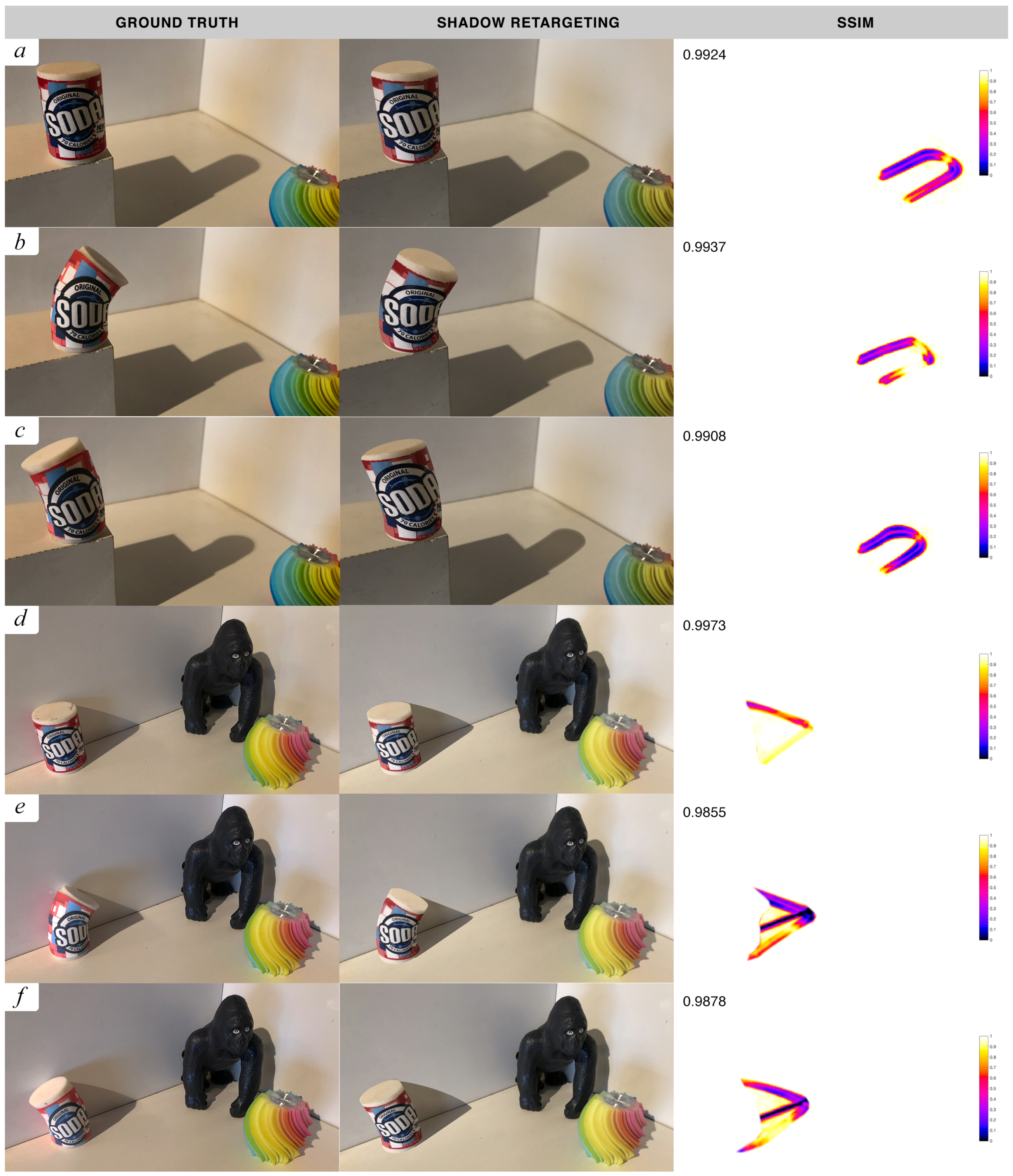
Figure 5 shows a comparison between ground-truth shadows and our retargeting algorithm. Figure 5a–d demonstrate the real-time capability of our algorithm for augmented reality. We performed texture deformation to animate the virtual-mesh and shadow samples to reconstruct occluded areas. Its key frames were 3D-printed in order to compare shadow retargeting with real-world shadows. SSIM results demonstrate good precision using our real shadow-retargeting technique, which may be improved with further accuracy of 3D markerless object registration and tracking. Figure 5e–g show results under High Dynamic Range (HDR) maps [36]. These demonstrate good precision in complex lighting scenarios, where we approximate multiple retargeted soft shadows. Figure 5h–j show synthetic results generated using Unity3D. These show the behaviour of our technique under single and multiple points of light from point- to area-emitting regions. Our method is able to deliver accurate retargeting under a variety of lighting conditions. SSIM comparisons show high accuracy on umbra and penumbra regions between ground truth and our retargeting approach.
Figure 8 shows comparisons between ground-truth shadows and our retargeting algorithm in complex settings. These results were captured using real-time augmented reality on an Apple iPhone X with Vuforia and ARKit frameworks. Software was developed using Unity3D. Figure 8a–c demonstrate the algorithm’s capability to handle an occluder placed distantly from the ground plane. Figure 8d–f show the adeptness of the method to handle light sources casting over multiple-receiver surfaces. Our algorithm uses SLAM techniques to detect the ground and vertical planes using the ARKit framework [40]. SSIM results demonstrate good precision using our real shadow-retargeting technique, whose accuracy may be further improved with 3D markerless object registration and tracking.
7.2. Real-Time Performance
From Figure 5, results Figure 5a–d were generated with an Apple iPhone X with an output resolution of 2436 px by 1125 px. These achieved interactive frame rates, on average, 25 fps in a scenario with a fixed point of view, and 20 fps, in one with camera movement. Results Figure 5e–j were generated in a 2.8 GHz Quad-core Intel Core i7 with 16 GB of RAM with an image size of 1280 by 720 px. These achieved a constant frame rate of 30 fps, which allowed us to reconstruct shadows in real time for modern video standards.
Table 1 breaks down the processing time of our technique under a fixed point of view setting. The primary bottleneck of our system is the discretised search for shadow reconstruction. On average, this takes one-third of the render time per frame. Nonetheless, the number of sample-search iterations is typically low, which makes the method suitable for interactive frame rates on low-powered mobile devices. Our approach proves to be consistent in rendering performance under different lighting scenarios.
7.3. Reconstruction Visualizations
As detailed in Section 4.3, when an occlusion is present in a region of the warped shadow, we perform shadow inpainting using a discretised concentric ring search for appearance sampling. Our method selects the closest nonoccluded texel. We used the binary mask from Figure 3c for segmenting the area in which probe sampling is appropriate. When multiple shadows are present, this is done for each of them being subsegmented by isolated and overlapping regions. Figure 9 displays the texel distance from sampling point for single and multiple light sources in hard- and soft-shadow scenarios. As can be observed in this figure, sampling distance is typically low, which leads to interactive frame rates, as presented in Table 1.
7.4. Estimated Light Sources
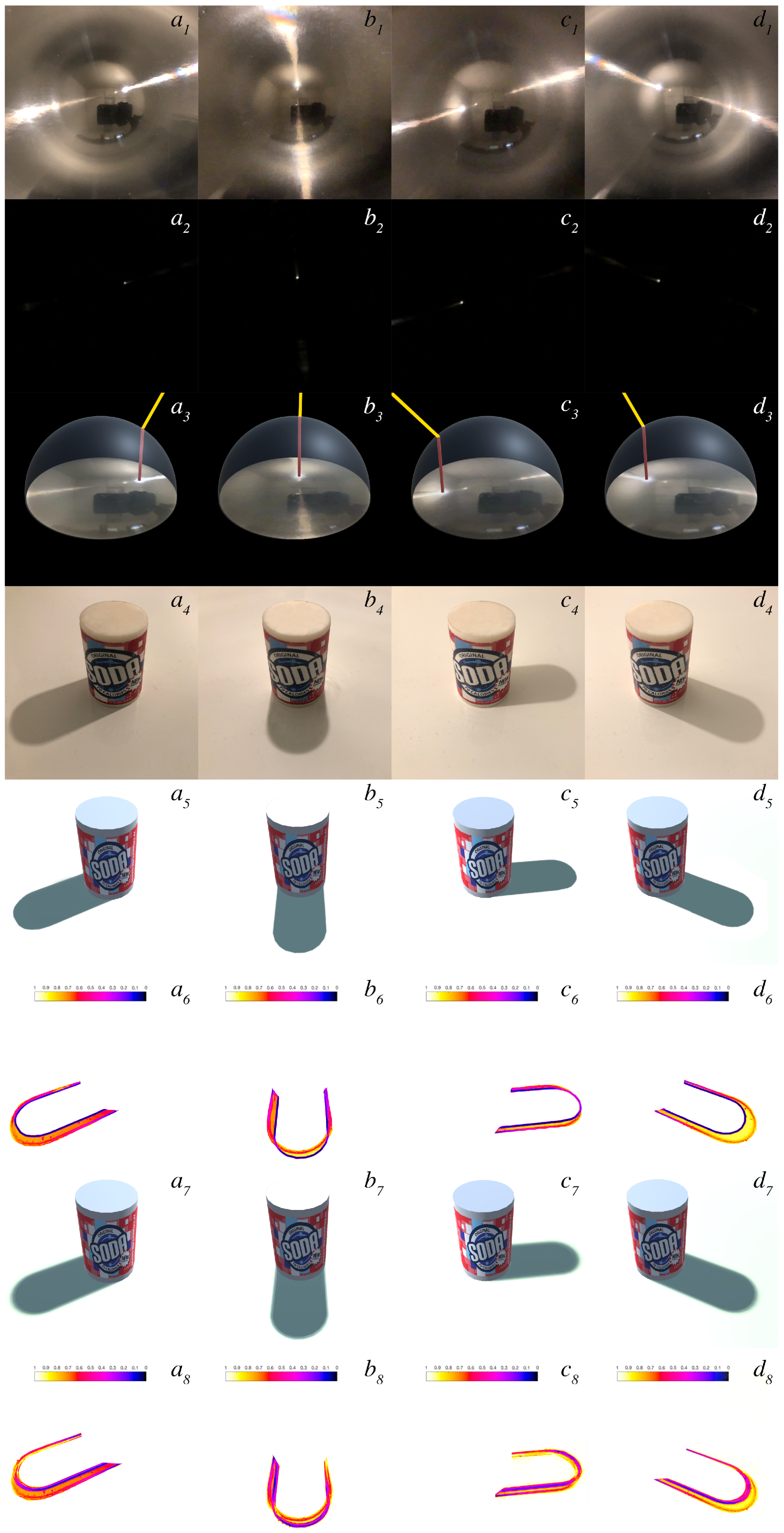
Figure 10 shows the results of estimated light-source directions following the approach described in Section 3. First row of results displays the environment lighting of the scene captured through flat Fresnel lenses. The second row shows underexposed images capturing the light-source point represented as highly saturated pixels within the image. Third row displays a visualization of the light-estimation algorithm following the projection from a flat Fresnel lens to a virtual superimposed hemisphere. Fourth row shows ground-truth shadows under real-world lighting. The fifth shows synthetic hard shadows cast from the centre of the highly saturated region with the flat Fresnel lens using our light-estimation algorithm. The sixth shows a comparison between ground truth and synthetic hard shadows. The seventh uses the radius of the highly saturated region to compute the penumbra area using PCSS. As can be seen in the last row of the figure, our algorithm is able to consistently estimate the light direction of the scene. Inaccuracies are prone to be present on the penumbra area. This can be observed in the normalized comparison between GT and those that are synthetically generated. Such inaccuracy is low and could further be reduced by enhancing the computation of the virtual light-source radius.
8. Future Work
The reference-point selection for the discretised concentric ring search algorithm could be further improved by sampling scene visibility. This would better estimate reconstructed shadow appearance. Additionally, this would allow for more advanced techniques to interpolate and even extrapolate the shadow to obtain more consistent results in even more complex scenarios. An approach based on bidirectional reprojection could resolve large deformations or topology changes in which occluder geometry is significantly altered from its physical position [42]. The impact of such schemes on mobile real-time performance remains uncertain.
The present method relies on lighting to be dominated by a few principal lights with their cast shadows. We could reconstruct the number of lights, directions, apparent angle, and intensity from the shadows. Since there are no models to directly reconstruct those parameters from physical shadows, we would use an iterative search to find the solution of this inverse problem. Additionally, the solution could be refined more efficiently, once the shadows are sufficiently close, by estimating the gradient of the distance function with respect to the solution parameters.
Our method holds plausibly for small-proximity displacements. Deformations made under the same visual axis are perceptually more precise. In the case of animated meshes that reveal a geometry not present in the reference model, visual artefacts appear due to disocclusions, addressed in part by inpainting. Large translations in the virtual object from the physical reference position cause lighting inconsistencies with spatial variations in the environment. Temporary inconsistencies between frames of animation may appear due to the reconstruction search performed in real time for occluded areas. These limitations could be surpassed by using a machine-learning model that would contain accurate predictions for retargeted poses under large translations or deformations. Finally, when performing reconstruction in a multiple-shadow scenario, we relied on sampling from a physical overlapping region of the shadow to maintain its appearance. Therefore, our method would fail to reconstruct if the physical shadow had no overlapping region that can be used to sample. We anticipate that this limitation could be surpassed by calculating the approximate overlapping appearance using the two projected individual shadows.
9. Conclusions
In this manuscript, we enhanced the capabilities of the shadow-retargeting approach presented by [1]. We introduced a light-estimation method that enables light-source detection using flat Fresnel lenses embedded in every-day objects. To do so, we proposed using flat Fresnel lens films for the reproduction of a chrome-ball sphere in a two-dimensional surface. Such a film is able to reproduce the reflection of a 180-degree sphere over a plane. Our method draws from a light-source estimation algorithm using chrome-ball spheres. This procedure allows the method to work without a set of pre-established conditions.
The proposed solution covers a more flexible and adaptable method for light estimation than previous approaches as very little configuration is required. It provides an unobtrusive and more user-friendly approach to estimate ambient lighting in an augmented-reality scenario. Nonetheless, the method requires flat Fresnel lenses to be visible within the frustum of the camera. If these are not visible, the last known light direction is used until lenses become visible by the camera again, which is often satisfactory for stable lighting conditions. Further, our approach relies on light sources to be visible as reflected in the lens for each illumination environment sample. If these light sources would become occluded, our approach would accordingly update the estimation. As such, the method is most appropriate given a distant illumination environment assumption.
To summarize, shadow retargeting is the first approach to retarget already present shadows from static objects against their overlaid movement with plausible coherent results [1]. Here, we enhanced the capabilities of the algorithm by handling camera movements and achieving plausible inpainted backgrounds over preregistered objects. We demonstrated the accuracy of the approach by presenting additional results that are able to handle shadows that are cast over multiple-receiver surfaces. Further, we accounted for accurate shadow retargeting when a non-grounded occluder is present in the scene.
Author Contributions
Conceptualization, L.C.C. and K.M. (Kenny Mitchell); methodology, L.C.C., M.F., and K.M. (Kenny Mitchell); software, L.C.C.; validation, L.C.C., M.F., and K.M. (Kenny Mitchell); formal analysis, L.C.C., M.F., and K.M. (Kenny Mitchell); investigation, L.C.C. and K.M. (Kenny Mitchell); resources, K.M. (Kieran Mclister) and M.K.; data curation, K.M. (Kenny Mitchell); writing and original-draft preparation, L.C.C. and K.M. (Kenny Mitchell); writing and review, L.C.C. and K.M. (Kenny Mitchell); visualization, L.C.C.; supervision, K.M. (Kenny Mitchell); project administration, K.M. (Kenny Mitchell); funding acquisition, K.M. (Kenny Mitchell).
Funding
This project received funding from the European Union’s Horizon 2020 research and innovation program under the Marie Sklodowska-Curie grant agreement No. 642841.
Conflicts of Interest
The authors declare no conflict of interest.
References
- Casas, L.; Fauconneau, M.; Kosek, M.; Mclister, K.; Mitchell, K. Image Based Proximate Shadow Retargeting. In Computer Graphics and Visual Computing (CGVC); The Eurographics Association: London, UK, 2018. [Google Scholar]
- Setlur, V.; Takagi, S.; Raskar, R.; Gleicher, M.; Gooch, B. Automatic image retargeting. In Proceedings of the ACM International Conference on Mobile and Ubiquitous Multimedia, Christchurch, New Zealand, 8–10 December 2005. [Google Scholar]
- Goferman, S.; Zelnik-Manor, L.; Tal, A. Context-Aware Saliency Detection. IEEE Trans. Pattern Anal. Mach. Intell. 2010, 34, 1915–1926. [Google Scholar] [CrossRef] [PubMed]
- Comport, A.I.; Marchand, E.; Pressigout, M.; Chaumette, F. Real-time markerless tracking for augmented reality: The virtual visual servoing framework. IEEE Trans. Vis. Comput. Graph. 2006, 12, 615–628. [Google Scholar] [CrossRef] [PubMed]
- Vuforia Object Recognition. Available online: https://developer.vuforia.com/ (accessed on 1 April 2018).
- Leão, C.W.M.; Lima, J.P.; Teichrieb, V.; Albuquerque, E.S.; Keiner, J. Altered reality: Augmenting and diminishing reality in real time. In Proceedings of the IEEE Virtual Reality, Singapore, 19–23 March 2011. [Google Scholar]
- Nowrouzezahrai, D.; Geiger, S.; Mitchell, K.; Sumner, R.; Jarosz, W.; Gross, M. Light Factorization for Mixed-Frequency Shadows in Augmented Reality. In Proceedings of the 10th IEEE International Symposium on Mixed and Augmented Reality, ISMAR, Basel, Switzerland, 26–29 October 2011. [Google Scholar]
- Takeuchi, Y.; Perlin, K. ClayVision: The (elastic) image of the city. In Proceedings of the SIGCHI Conference on Human Factors in Computing Systems, Austin, TX, USA, 5–10 May 2012; pp. 2411–2420. [Google Scholar]
- Magnenat, S.; Ngo, D.T.; Zünd, F.; Ryffel, M.; Noris, G.; Rothlin, G.; Marra, A.; Nitti, M.; Fua, P.; Gross, M.; et al. Live Texturing of Augmented Reality Characters from Colored Drawings. IEEE Trans. Vis. Comput. Graph. 2015, 21, 1201–1210. [Google Scholar] [CrossRef] [PubMed]
- Casas, L.; Kosek, M.; Mitchell, K. Props Alive: A Framework for Augmented Reality Stop Motion Animation. In Proceedings of the 2017 IEEE 10th Workshop on Software Engineering and Architectures for Realtime Interactive Systems, Los Angeles, CA, USA, 18–19 March 2017. [Google Scholar]
- Mann, S. Fundamental issues in mediated reality, WearComp, and camera-based augmented reality. In Fundamentals of Wearable Computers and Augmented Reality; Lawrence Erlbaum Associates: Mahwah, NJ, USA, 2001. [Google Scholar]
- Bertalmio, M.; Sapiro, G.; Caselles, V.; Ballester, C. Image inpainting. In Proceedings of the 27th Annual Conference on Computer Graphics and Interactive Techniques, New Orleans, LA, USA, 23–28 July 2000. [Google Scholar]
- Bertalmio, M.; Vese, L.; Sapiro, G.; Osher, S. Simultaneous Structure and Texture Image Inpainting. IEEE Trans. Image Process. 2003, 12, 882–889. [Google Scholar] [CrossRef] [PubMed]
- Herling, J.; Broll, W. PixMix: A real-time approach to high-quality Diminished Reality. In Proceedings of the 11th IEEE International Symposium on Mixed and Augmented Reality (ISMAR), Atlanta, GA, USA, 5–8 November 2012. [Google Scholar]
- Zhang, L.; Zhang, Q.; Xiao, C. Shadow Remover: Image Shadow Removal Based on Illumination Recovering Optimization. IEEE Trans. Image Process. 2015, 24, 4623–4636. [Google Scholar] [CrossRef] [PubMed]
- Jarusirisawad, S.; Saito, H. Diminished reality via multiple hand-held cameras. In Proceedings of the 2007 1st ACM/IEEE International Conference on Distributed Smart Cameras, ICDSC, Vienna, Austria, 25–28 September 2007; pp. 251–258. [Google Scholar]
- Kawai, N.; Sato, T.; Yokoya, N. Diminished reality considering background structures. In Proceedings of the 2013 IEEE International Symposium on Mixed and Augmented Reality, ISMAR 2013, Adelaide, SA, Australia, 1–4 October 2013. [Google Scholar]
- Mori, S. Diminished Hand: A Diminished Reality-Based Work Area Visualization. In Proceedings of the 2017 IEEE Virtual Reality, Los Angeles, CA, USA, 18–22 March 2017. [Google Scholar]
- Knecht, M.; Dünser, A.; Traxler, C.; Wimmer, M.; Grasset, R. A Framework For Perceptual Studies in Photorealistic Augmented Reality. In Proceedings of the 3rd IEEE VR 2011 Workshop on Perceptual Illusions in Virtual Environments, Singapore, 19 March 2011; pp. 27–32. [Google Scholar]
- Calian, D.; Mitchell, K.; Nowrouzezahrai, D.; Kautz, J. The Shading Probe: Fast Appearance Acquisition for Mobile AR. In SIGGRAPH Asia 2013 Technical Briefs; ACM: Hong Kong, China, 2013. [Google Scholar]
- Unger, J.; Gustavson, S.; Ynnerman, A. Spatially varying image based lighting by light probe sequences: Capture, processing and rendering. Vis. Comput. 2007, 23, 453–465. [Google Scholar] [CrossRef]
- Ramamoorthi, R.; Hanrahan, P. An efficient representation for irradiance environment maps. In Proceedings of the 28th Annual Conference on Computer Graphics and Interactive Techniques, SIGGRAPH 2001, Los Angeles, CA, USA, 12–17 August 2001; pp. 497–500. [Google Scholar]
- Jung, Y.; Franke, T.; Dähne, P.; Behr, J. Enhancing X3D for advanced MR appliances. In Proceedings of the Twelfth International Conference on 3D Web Technology—Web3D ’07, Perugia, Italy, 15–18 April 2007; p. 27. [Google Scholar]
- Franke, T.; Jung, Y. Precomputed radiance transfer for X3D based mixed reality applications. In Proceedings of the 13th international symposium on 3D web technology—Web3D ’08, Los Angeles, CA, USA, 9–10 August 2008; p. 7. [Google Scholar]
- Grosch, T. Differential Photon Mapping-Consistent Augmentation of Photographs with Correction of all Light Paths. In Eurographics (Short Presentations); 2005; pp. 53–56. Available online: http://www.rendering.ovgu.de/rendering_media/downloads/publications/DifferentialPhotonMapEG05-p-45.pdf (accessed on 1 April 2019).
- Grosch, T.; Eble, T.; Mueller, S. Consistent interactive augmentation of live camera images with correct near-field illumination. In Proceedings of the 2007 ACM Symp. Virtual Real. Softw. Technol.—VRST ’07, Newport Beach, CA, USA, 5–7 November 2007; p. 125. [Google Scholar]
- Knecht, M.; Mattausch, O. Differential Instant Radiosity for Mixed Reality. In Proceedings of the 9th IEEE International Symposium on Mixed and Augmented Reality 2010, ISMAR 2010, Seoul, Korea, 13–16 October 2010. [Google Scholar]
- Basri, R.; Jacobs, D.; Kemelmacher, I. Photometric Stereo with General, Unknown Lighting. Int. J. Comput. Vis. 2007, 72, 239–257. [Google Scholar] [CrossRef]
- Knorr, S.B.; Kurz, D. Real-time illumination estimation from faces for coherent rendering. In Proceedings of the ISMAR 2014—IEEE International Symposium on Mixed and Augmented Reality, Munich, Germany, 10–12 September 2014; pp. 349–350. [Google Scholar]
- Boom, B.J.; Orts-Escolano, S.; Ning, X.X.; McDonagh, S.; Sandilands, P.; Fisher, R.B. Interactive light source position estimation for augmented reality with an RGB-D camera. Comput. Anim. Virtual Worlds 2017, 28, e1686. [Google Scholar] [CrossRef]
- Mandl, D.; Yi, K.M.; Mohr, P.; Roth, P.M.; Fua, P.; Lepetit, V.; Schmalstieg, D.; Kalkofen, D. Learning Lightprobes for Mixed Reality Illumination. In Proceedings of the 2017 IEEE International Symposium on Mixed and Augmented Reality (ISMAR), Nantes, France, 9–13 October 2017; pp. 82–89. [Google Scholar]
- Sato, I.; Sato, Y.; Ikeuchi, K. Illumination distribution from shadows. In Proceedings of the Computer Vision and Pattern Recognition (CVPR), Fort Collins, CO, USA, 23–25 June 1999. [Google Scholar]
- Haller, M.; Drab, S.; Hartmann, W. A real-time shadow approach for an augmented reality application using shadow volumes. In Proceedings of the ACM Symposium on Virtual Reality Software and Technology, Osaka, Japan, 1–3 October 2003. [Google Scholar]
- Jacobs, K.; Nahmias, J.D.; Angus, C.; Reche, A.; Loscos, C.; Steed, A. Automatic generation of consistent shadows for augmented reality. In Proceedings of the ACM International Conference Proceeding Series, Victoria, BC, Canada, 9–11 May 2005; p. 113. [Google Scholar]
- Castro, T.K.D.; Figueiredo, L.H.D.; Velho, L. Realistic shadows for mobile augmented reality. In Proceedings of the 14th Symposium on Virtual and Augmented Reality, SVR 2012, Rio Janiero, Brazil, 28–31 May 2012. [Google Scholar]
- Debevec, P. Rendering Synthetic Objects into Real Scenes: Bridging Traditional and Image-based Graphics with Global Illumination and High Dynamic Range Photography. In Proceedings of the ACM SIGGRAPH ’98 Proceeding, Los Angeles, CA, USA, 11–15 August 1998. [Google Scholar]
- Blinn, J. Me and My (Fake) Shadow. IEEE Comput. Graph. Appl. 1988, 8, 82–86. [Google Scholar]
- Kajiya, J.T. The Rendering Equation. SIGGRAPH Comput. Graph. 1986, 20, 143–150. [Google Scholar] [CrossRef]
- Fernando, R. Percentage-closer Soft Shadows. In ACM SIGGRAPH Sketches on SIGGRAPH; Los Angeles, CA, USA, 2005; Available online: http://download.nvidia.com/developer/presentations/2005/SIGGRAPH/Percentage_Closer_Soft_Shadows.pdf (accessed on 1 April 2019).
- ARKit. Apple ARKit. Available online: https://developer.apple.com/arkit/ (accessed on 1 April 2018).
- Mur-Artal, R.; Montiel, J.M.M.; Tardós, J.D. ORB-SLAM: A Versatile and Accurate Monocular SLAM System. IEEE Trans. Robot. 2015, 31, 1147–1163. [Google Scholar] [CrossRef] [Green Version]
- Yang, L.; Tse, Y.C.; Sander, P.V.; Lawrence, J.; Nehab, D.; Hoppe, H.; Wilkins, C.L. Image-based Bidirectional Scene Reprojection. ACM Trans. Graph. 2011, 30, 1–10. [Google Scholar]
Figure 1.
(a) Reference physical toy lion as observed by a mobile phone camera. (b) The virtual lion rendered at the same pose with (b) a regular shadow map approach and (c) with Shadow Retargeting. (d) Its movement retargeted according to a sequence of geometry poses in AR towards seamless appearance preservation.

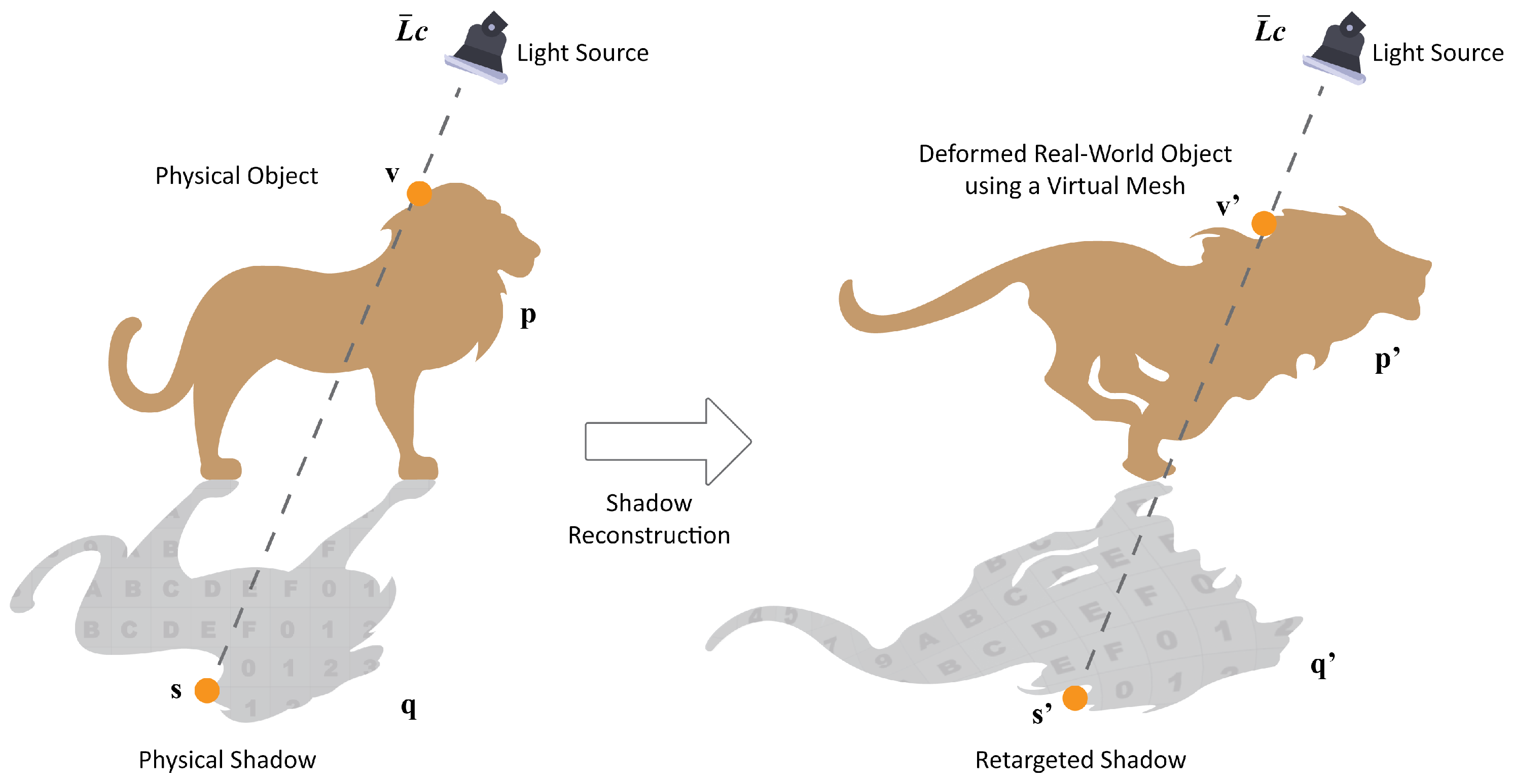
Figure 2.
p: real-world static object; q: physical projected shadow; v: vertex from coincident overlaid mesh; s: (v) being projected to the floor; p’: deformed real-world object using a mesh; q’: retargeted projected shadow; v’: same initial vertex (v) being animated over time; and s’: v’ being projected to the floor.

Figure 3.
(a) Mask for physical-object pose. (b) Mask for physical-shadow pose. (c) Mask containing the valid shadow area eligible for appearance sampling.
Figure 3.
(a) Mask for physical-object pose. (b) Mask for physical-shadow pose. (c) Mask containing the valid shadow area eligible for appearance sampling.

Figure 4.
Discretised concentric-ring search algorithm for plausible shadow reconstruction. Red samples are trivially masked and rejected as ineligible. The closest eligible texel, illustrated as a green sample, was used for appearance sampling.
Figure 4.
Discretised concentric-ring search algorithm for plausible shadow reconstruction. Red samples are trivially masked and rejected as ineligible. The closest eligible texel, illustrated as a green sample, was used for appearance sampling.

Figure 5.
Comparisons of ground truth with our shadow-retargeting scheme. (a–d) Real-3D printed nondeformed-object shadow retargeted with single/double light sources, and hard/soft shadows. (e–g) Synthetic renders with classic light probes showing retargeted complex shadows. (h–j) Effect of progression of point to area lighting retargeted from a rendered source image with character in bind pose.

Figure 6.
(i) Observed background without the reference physical toy lion and shadow on it. (ii) Real-world scene as observed by a mobile-phone camera. (iii) Virtual lion in a retargeted pose and shadow with the revealed background reconstructed.
Figure 6.
(i) Observed background without the reference physical toy lion and shadow on it. (ii) Real-world scene as observed by a mobile-phone camera. (iii) Virtual lion in a retargeted pose and shadow with the revealed background reconstructed.

Figure 7.
(a) Ground-truth (GT) shadow generated by a physical occluder. (b) Uniform simple estimated shadow. (c) Virtual shadow rendered using our method. Structural Similarity Index Metric (SSIM) comparisons of GT with (b) above and (c) below, showing improved accuracy through shadow retargeting.
Figure 7.
(a) Ground-truth (GT) shadow generated by a physical occluder. (b) Uniform simple estimated shadow. (c) Virtual shadow rendered using our method. Structural Similarity Index Metric (SSIM) comparisons of GT with (b) above and (c) below, showing improved accuracy through shadow retargeting.

Figure 8.
Comparisons of ground truth with our shadow-retargeting scheme in complex settings. (a–c) Real 3D-printed nondeformed-object shadow retargeted with an occluder placed distantly from the ground plane. (d–f) Real 3D-printed nondeformed-object shadow retargeted with a unique light source casting over multiple-receiver surfaces.

Figure 9.
Row i: reconstructed shadows at a retargeted pose. Row ii: colour-encoded visualisations between distance from the occluded to the sampled texel, used as shadow probe. Results (a–c) were generated under a single light source casting hard shadows. Results (d–f) were generated under multiple light sources casting soft shadows.

Figure 10.
(Row 1) Environment lighting captured through flat Fresnel lenses. (Row 2) Underexposed images that capture the light-source point represented as highly saturated pixels within the image. (Row 3) Visualization of light-estimation algorithm. (Row 4) Ground-truth shadows. (Row 5) Synthetic hard shadows cast from the centre of the highly saturated region with the flat Fresnel lens. (Row 6) Comparison between ground truth and synthetic hard shadows. (Row 7) Synthetic soft shadows using the radius of the highly saturated region for the penumbra area using Percentage-Closer Soft Shadows (PCSS). (Row 8) Comparison between ground truth and synthetic soft shadows with reduced error.


Table 1.
Time breakdown of a typical frame processed using our shadow-retargeting method on an Apple iPhone X.
Table 1.
Time breakdown of a typical frame processed using our shadow-retargeting method on an Apple iPhone X.
| Task | Time | Percentage |
|---|---|---|
| Object Registration | 1.83 ms | 4.43% |
| Auxiliary masks (Figure 3a–c) | 2.59 ms | 6.27% |
| Object Appearance Retargeting | 1.93 ms | 4.67% |
| Shadow Warping | 3.13 ms | 7.57% |
| Discretized Search | 15.78 ms | 38.20% |
| Uniform Shadow Blurring | 7.36 ms | 17.82% |
| Percentage Closer Soft Shadows | 5.27 ms | 12.76% |
| Background Inpainting | 2.43 ms | 5.88% |
| Scene Rendering | 0.98 ms | 2.37% |
| Total | 41.3 ms | 100% |
© 2019 by the authors. Licensee MDPI, Basel, Switzerland. This article is an open access article distributed under the terms and conditions of the Creative Commons Attribution (CC BY) license (http://creativecommons.org/licenses/by/4.0/).
Share and Cite
MDPI and ACS Style
Casas Cambra, L.; Fauconneau, M.; Kosek, M.; Mclister, K.; Mitchell, K. Enhanced Shadow Retargeting with Light-Source Estimation Using Flat Fresnel Lenses. Computers 2019, 8, 29. https://0-doi-org.brum.beds.ac.uk/10.3390/computers8020029
AMA Style
Casas Cambra L, Fauconneau M, Kosek M, Mclister K, Mitchell K. Enhanced Shadow Retargeting with Light-Source Estimation Using Flat Fresnel Lenses. Computers. 2019; 8(2):29. https://0-doi-org.brum.beds.ac.uk/10.3390/computers8020029
Chicago/Turabian StyleCasas Cambra, Llogari, Matthias Fauconneau, Maggie Kosek, Kieran Mclister, and Kenny Mitchell. 2019. "Enhanced Shadow Retargeting with Light-Source Estimation Using Flat Fresnel Lenses" Computers 8, no. 2: 29. https://0-doi-org.brum.beds.ac.uk/10.3390/computers8020029
Note that from the first issue of 2016, this journal uses article numbers instead of page numbers. See further details here.