Risk Reduction Optimization of Process Systems under Cost Constraint Applying Instrumented Safety Measures †


Faculty of Software Engineering and Computer Technigue, ITMO University, 197101 Saint-Petersburg, Russia
*
Author to whom correspondence should be addressed.
†
This paper is an extended version of our report: Moshnikov A. “Process safety instrument system optimization by Monte-Carlo method” in the Majorov International Conference on Software Engineering and Computer Systems (MICSECS 2019), Saint-Petersburg, Russia, 12–13 December 2019.
Computers 2020, 9(2), 50; https://0-doi-org.brum.beds.ac.uk/10.3390/computers9020050
Submission received: 12 May 2020
/
Revised: 12 June 2020
/
Accepted: 16 June 2020
/
Published: 19 June 2020
(This article belongs to the Special Issue Selected Papers from MICSECS 2019)
Abstract
:This article is devoted to an approach to develop a safety system process according to functional safety standards. With the development of technologies and increasing the specific energy stored in the equipment, the issue of safety during operation becomes more urgent. Adequacy of the decisions on safety measures made during the early stages of planning the facilities and processes contributes to avoiding technological incidents and corresponding losses. A risk-based approach to safety system design is proposed. The approach is based on a methodology for determining and assessing risks and then developing the necessary set of safety measures to ensure that the specified safety indicators are achieved. The classification of safety measures is given, and the model of risk reduction based on deterministic analysis of the process is considered. It is shown that the task of changing the composition of safety measures can be represented as the knapsack discrete optimization problem, and the solution is based on the Monte Carlo method. A numerical example is provided to illustrate the approach. The considered example contains a description of failure conditions, an analysis of the types and consequences of failures that could lead to accidents, and a list of safety measures. Solving the optimization problem used real reliability parameters and the cost of equipment. Based on the simulation results, the optimal composition of the safety measures providing cost minimization is given. This research is relevant to engineering departments, who specialize in planning and designing technological solutions.
1. Introduction
With the development of technologies and increasing the specific energy stored in the equipment, the issue of safety during operation becomes more urgent. To ensure safety, emergency protection systems have been widely used. As examples of industrial systems that fit the description, we can consider a polar crane, a chemical plant reservoir system, and a turbine. At the heart of the development of such protection systems is the international standard IEC 61511 [1], which introduces the term “safety instrument system” (SIS) and defines it as a system consisting of sensors, logic solvers, and final element controls. Together they implement one or more functions that provide safety [2]. Such systems may contain a set of safety features that act as layers or barriers aimed at deeply layered risk reduction as the first level of protection, we can consider a distributed control system [3], which is designed to ensure the technology of the process and the formation of control in the normal operation of the equipment. The next barrier is the emergency shutdown system (implemented on the SIS), which brings the object to a safe controlled state. The development of the design of the SIS for industrial facilities is associated with the choice of architecture, nomenclature of components, aspects related to the discipline of service and additional measures to guarantee the development [4]. The content of the article is devoted to optimizing the composition of safety measures, that is, the priority is given to the approach of how to protect the technological process in the event of equipment failures. The first part of the article also focuses on how such development should be carried out, i.e., on the organization of the life cycle in terms of development, namely, how the process of security analysis is related to development and how the main stages of development are provided with the help of regulatory documents.
2. Risk Reduction Approach
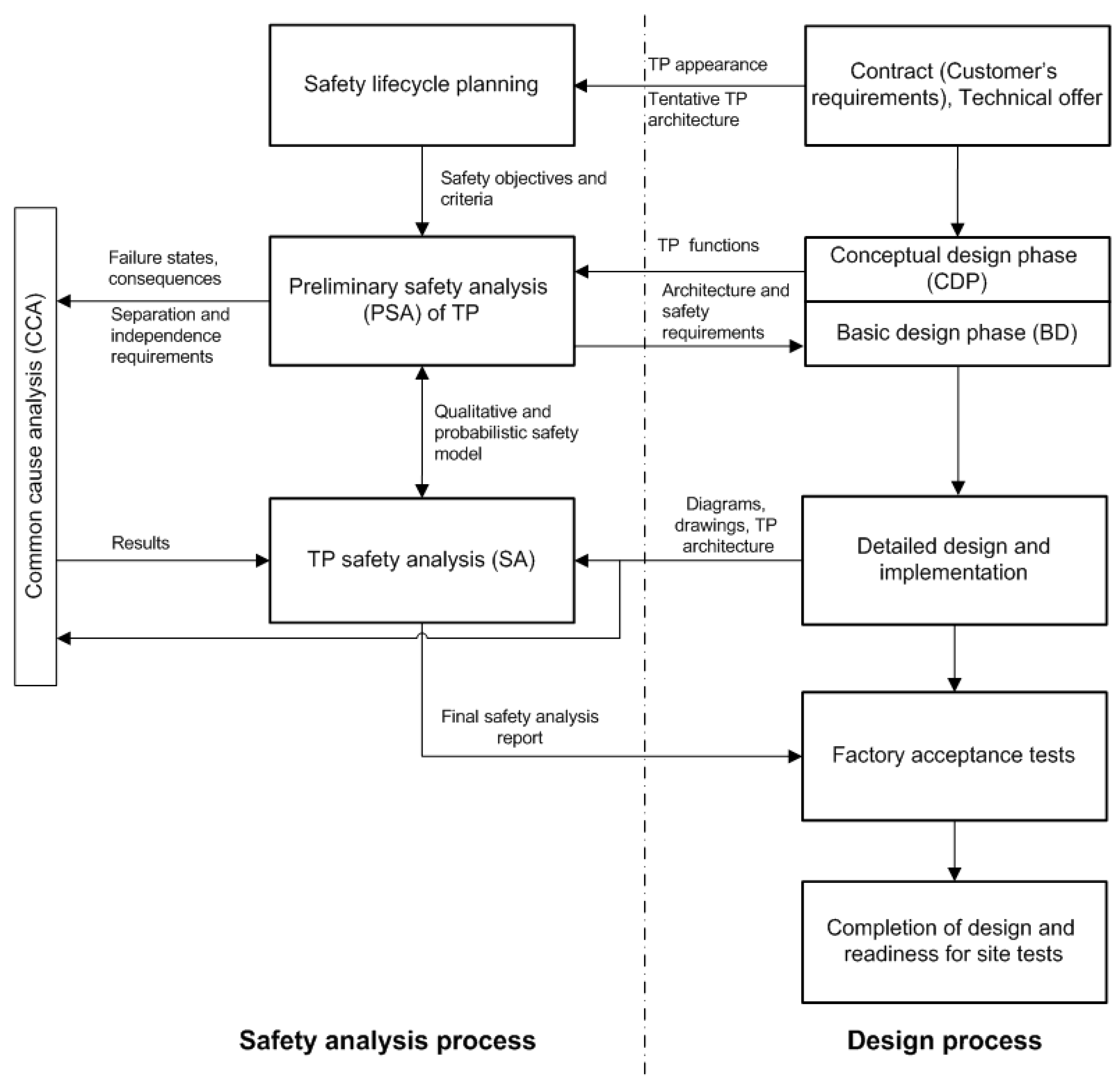
2.1. Relationship of the Safety Analysis and the Design Process
Safety properties are set during the design process. This is ensured by applying a special development lifecycle-focused on safety. At the same time, the safety analysis process takes place in parallel with the development of the main documents. As a result of this approach, an array of protective measures is formed, some of which can be transferred from previous successful projects and applications.
A risk-based approach is used to ensure safety requirements, which consists of close integration of equipment development and safety analysis processes. Below is a detailed description of the basic safety analysis steps during design.
- Safety lifecycle planning: the first and foremost step of the safety analysis is collection of input data, formulation of technological process (TP) safety criteria and objectives. The selection of standards that will be applied to prove the safety level is justified in the frames of safety lifecycle planning.
- Preliminary safety analysis (PSA): All functions of technological process equipment are assessed to discover potential functional failures, and hazards connected with particular failure states are classified. The preliminary safety analysis systematizes requirements and criteria laid down in the contract (tender documentation) and provides a preliminary proof of that the proposed technological process equipment architecture can ensure fulfillment of these requirements, justifies the necessity of introducing protective measures, additional assemblies and functionality. The PSA is updated throughout the entire duration of the development process.
- Technological process safety analysis: collection, analysis and documenting the results, proving that the design, control system architecture, and selected components meet the safety requirements and objectives.
- Common cause analysis sets requirements for physical and functional separation, isolation, and independence of technological process elements.
The relation of the design process and the safety analysis is shown in Figure 1.
2.2. Risks Classification and Safety Barriers Design
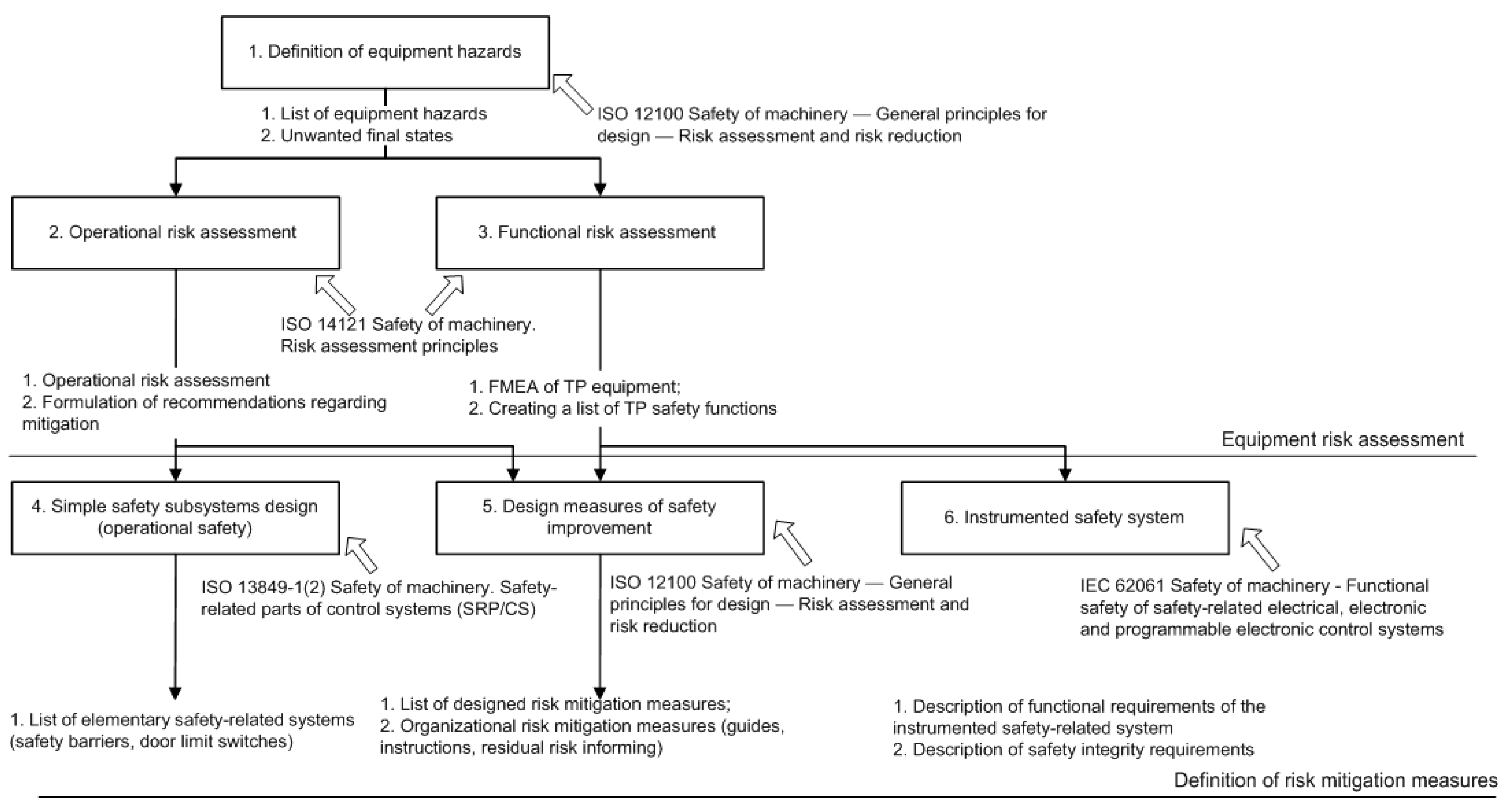
Preliminary risk analysis is based on an assessment of potential hazards. Potential risks (the risk means a hazard containing a quantitative assessment of the frequency and severity of consequences) can be divided into different groups which are related to operational and technical (functional) hazards. The general list of risks necessary for the analysis is provided in ISO 12100 [5]. The risks can be considered as hazards associated with the equipment itself, with its failures and external hazards associated with the actions of operators, and the loss of electricity and power supply.
Reducing the risk and achieving the necessary level of safety is achieved by using a system of safety barriers. A recommended way to classify barrier systems is shown in Figure 2. However, note that active barrier systems are often based on a combination of technical and human/operational elements. Even though different words are applied, the classification in the fourth level in Figure 2 is similar to the classification suggested by Hale [6]. A safety barrier is a physical and/or non-physical means planned to prevent, control, or mitigate undesired events or accidents As regards the continuous time aspect, some barrier systems are available (functioning continuously), while some are off-line (need to be activated). Further, some barriers are permanent, while some are temporary. Permanent barriers are implemented as an integrated part of the whole operational life cycle, while temporary barriers only are used in a specified time period, often during specific activities or conditions.
Authors [8] note that identifying technical (physical) safety barriers, usually, is quite simple, but in the case where the safety barrier includes an action, for example, the operator’s response to an alarm, you should be careful and distinguish between the action itself, which performs the barrier function, and the factors that help the operator in making the correct decision (technological instructions, training, precise information presentation, etc.) [9] offers a somewhat different approach classification of safety barriers based on evaluating their effectiveness in the event of a potentially dangerous situation. The degree of efficiency (high, medium, low) distinguishes the following types of safety barriers. Technical (high efficiency) barriers can prevent the spread of risk factors, reduce the risk of a situation, mitigate the consequences, or reduce the likelihood of risk factors [9]. Various technical barriers provide selective action against possible failures and external threats. The same applies to further escalation from the triggering event to consequences. The following subcategories are distinguished technical barriers: technical barriers that are triggered on demand (emergency cut-off valve, drencher system, emergency tank); technical passive, operate on a permanent basis, perform barrier function by its mere presence (safety valve, collapse, fire-proof and explosion-proof partitions etc.); technical control barriers that activate other barriers that prevent or mitigate the consequences of a dangerous event (gas detectors, fire alarm system, accident notification system, etc.).
Figure 3 shows how to develop requirements for safety barriers.
Barriers of this type cannot prevent the development of the accident, but can activate other barriers that will do this. Human (organizational) (average efficiency) barriers contribute to the control of a process or activity. This type of barrier can reduce the probability of the triggering event by strengthening other barriers or preventing them from being weakened, but if a potentially dangerous event has already been initiated, then this type of barrier can prevent its development or reduce the consequences. The following subcategories are distinguished: types of barriers: procedural (inspections and observations, control tools, process management, work risk assessment, work permit system etc.); human (operational) (control by the operator, supervision, periodic detours, etc.); and fundamental (low efficiency in the immediate vicinity of the event). Their effect is divided in time from the occurrence of the threat to the implementation of the factor risk.
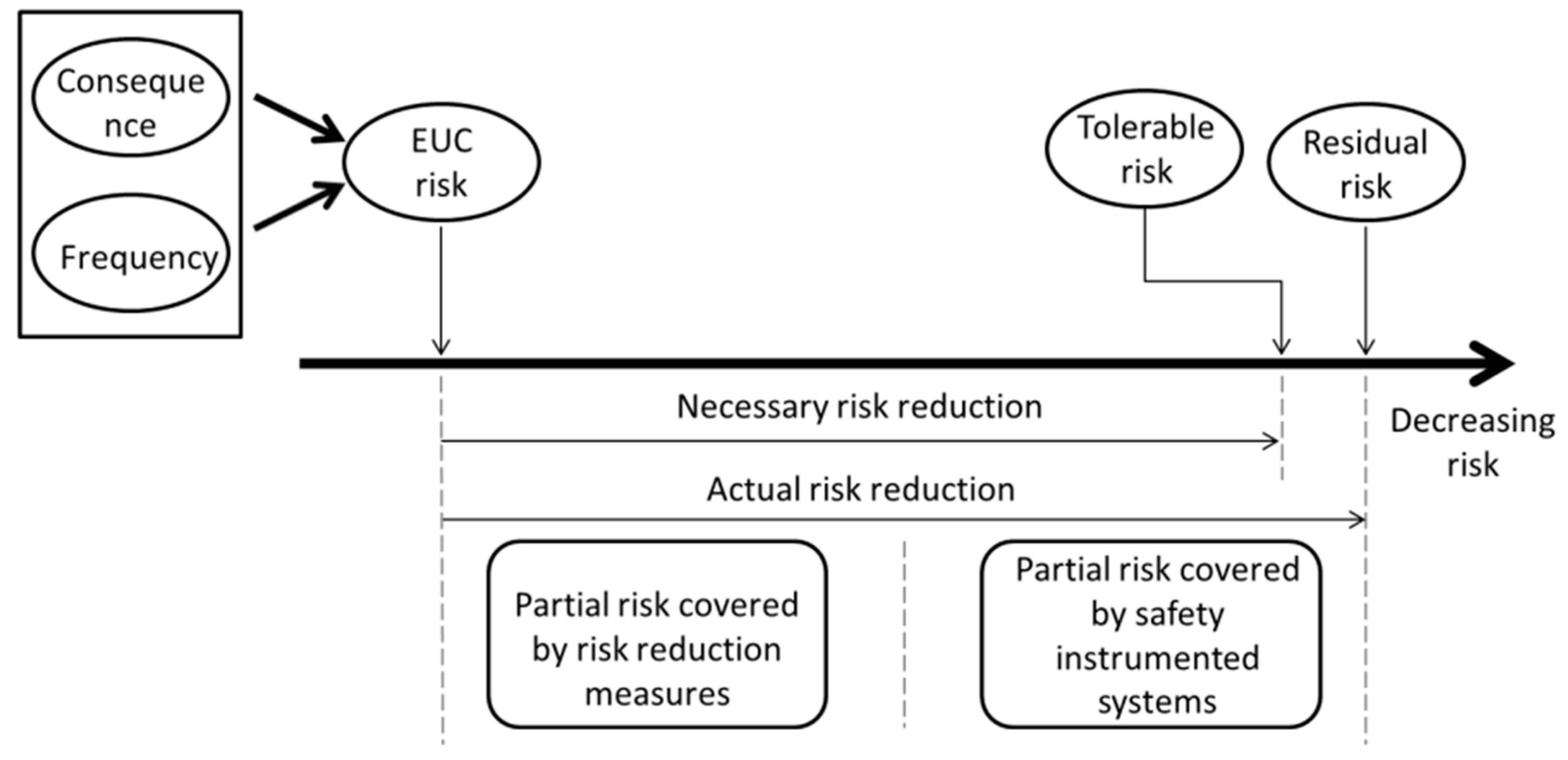
2.3. Risk Reduction and SIS
Risk reduction of Equipment under control (EUC) or technological process is shown in Figure 4.
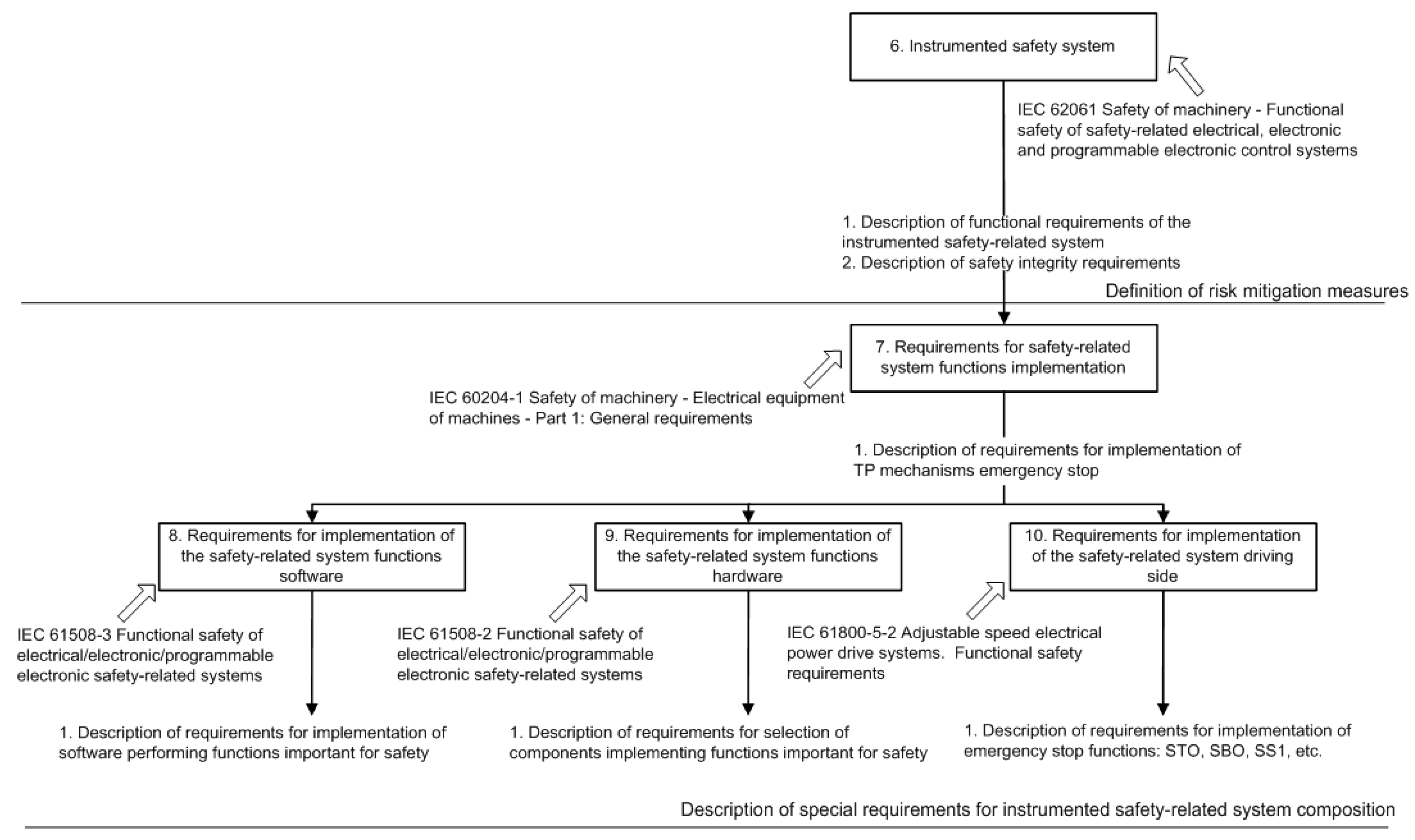
However, fundamental barriers make a significant difference and an important and effective contribution to the safety of the system by providing checks and controls for vulnerable systems and the original causes of failures. The following subcategories are distinguished by these types of barriers: fundamental procedural (analysis of the project, assessment of commissioning, checking the internal regulations, analysis of operation, confirmation of qualification); and fundamental human (good health of workers, etc.) [11]. A number of standards and guidelines have been issued to assist in designing, implementing, and maintaining reliable SISs. The most important of these is the international standard [2], which is a generic standard that outlines key requirements to all phases of the SIS life-cycle. The approach to developing safety functions related to a computer instrumental safety system is shown in Figure 5.
For some specific computer systems such as cluster computing systems, especially real-time, the key is to ensure reliability and fault tolerance while maintaining the continuity of the computing process. The achievement of high and stable performance indicators, reliability, fault tolerance [13] and security of computer systems is facilitated by the use of technologies for consolidation of clustering and virtualization resources [14], accompanied by replication and migration of virtual machines between physical servers. Migration and replication of virtual machines speeds up the reconfiguration process after failures of physical resources and contributes to supporting the continuity of the computing process required for managing cyber-physical systems and real-time technological processes.
3. Risk Reduction and Optimization
3.1. Problem Statement
The problem of optimizing the composition of the safety barriers and SIS is to select the necessary and sufficient set of sensors, logic elements and final performers, taking into account the constraints on the budget of the project. It is considered that any safety measures, applying the principle of risk reduction down to acceptable level [15]. Which protective measure has an estimated level of risk reduction factor (RRF). The main objective of all protective measures is to provide protection and reduce the initial risk level to an acceptable level.
The level of risk reduction taking into account safety barriers is shown in the Figure 6.
The purpose of this work is to solve the problem of optimization of the choice of a set of safety measures used in SIS, with the provision of specified safety requirements and cost.
The event tree (ETA) serves as a convenient and visual tool for representing security measures oriented to source events. This type of analysis has been widely used in probabilistic risk assessment of nuclear power plants. The application of ETA is described in detail in [16].
The probability of failure of safety measures can be determined by q(t) = e−λt, where λ is the equipment failure rate. Cascading failures and common case failures are not considered in this approach.
In general, we can introduce:
- qi—probability of failure of the i-th component of the process system;
- Sj—the cost of implementing the j-th safety measure;
- qlockj—the probability of failure of the j-th lock;
- qemsj—the probability of failure of j-th emergency stop;
- qdiagj—probability of failure of the j-th diagnosis, revealing pre-emergency conditions; and
- qreq—the probability of occurrence of a dangerous situation, specified in regulations or determined during the analysis.
3.2. Approach to the Optimization Problem Solving
The problem of optimization of the choice of safety measures is a modification of the “Backpack Problem” [18], a class of combinatorial optimization problems, which can be formulated as follows:
where pj and ωi,j are weights, and ci is a cost, and x = (x1, ..., xn).
The backpack problem can be solved in several ways: the method of dynamic programming [19]; brute force; the method of branches and boundaries [20]; the method of statistical modeling. Consider the application of the statistical modeling method. In general, the approach can be represented as follows, find the maximum of the function S(x) on a given set X. Let us assume that the maximum is achieved for only one value of the parameter x*. Let us denote the maximum by γ*.
Optimization problem can be related to the calculation of probability l = P(S(X) ≥ γ), where X has some probability density f(x; u) on the set X (for example, having a uniform distribution density) and γ is close to the unknown γ∗. As is correct, l is the probability of a rare event, so a sampling-by-significance approach can be used. Thus, sampling from such a distribution yields optimal or nearly optimal values. The last value γ∗ = γ is usually unknown, but using statistical modeling, a sequence is formed at each step of the simulation, which tends to the optimal γ∗, as well as at each step the change of the modeled vector is fixed [21,22,23].
3.3. Algorithm of Monte Carlo Simulation
1. Choose the initial vector of parameters , let elite selection be , -parameter. Take the counter t = 1;
2. Generate N random vectors with density , determine the values of effect S(Xi) for all i, and arrange them in ascending order from smaller to larger: .
Let γt be the (1 − e) quintile of the obtained values, thus ;
3. Using the same sample of random vectors solve the equation denote the solution as , where I is indicator function (I = 1 if , and 0 otherwise)
4. If the stop criterion is reached, then end the algorithm, otherwise change the counter t = t + 1 and proceed to step 2.
4. Model of Technological Process Subsystem
4.1. Model Description
As an example, we will consider the fuel supply subsystem, which includes a fixed volume tank (Tank), a level sensor (LV), a pumping valve to the next section of the process (V1), and a feed pump (PD) with a control system implemented on the control unit (CU). During the preliminary analysis, it was revealed that two dangerous conditions are possible at this site: the occurrence of a fire and its propagation, as well as tank overflow. Assume that the required probability of preventing the development of fire and exceeding the level in the tank should be less than 1 × 10⁻⁵ and 1 × 10⁻⁴ per year, respectively. Modeling of safety-related systems is based on the theory of reliability. To describe the possible consequences of failures of the main equipment, FMEA analysis of the subsystem equipment is used, the analysis is performed for the operating mode. The qualitative analysis as the failure mode and effect analysis (FMEA) of the technological process subsystem in accordance with [1] is given in Table 1.
Safety measures D1–D3 to ensure control are taken continuously.
Following methods for assessing reliability: Quantitative evaluation using simplified equations based on block diagrams of reliability and analysis of failure trees [24]. In some cases, Markov analysis can be used, a more complex approach allows working with dynamic models that take into account the development of failure over time [25]. Taking into account various variants of implementation of safety measures it is possible to receive the following optimization problem [26]:
It is needed to find the vector B = {b1, b2…b9}, at which (1) is executed, on a set of initial data from Tables 2 and 3. For example, the vector B = {1, 0, 1, 0, 0, 0, 1, 0, 0} means that, as part of the safety instrument system, safety measures are used: monitoring the condition of the tank body by the ultrasonic method (D1), monitoring the condition of the feed pump windings (D3), emergency opening of the drain valve (Z3). The total number of combinations 29 = 512. In this example, for clarity, the number of options is not so large; in real systems, the number of combinations can reach very large values.
4.2. Model Initial Data
The initial data on the reliability of the equipment of the production line and safety measures are presented in Table 2 and Table 3, respectively.
The fuel supply subsystem works 8760 h a year, without safety measures: qfire = 4.36 × 10⁻², qo.l. = 7.43 × 10⁻³.
To assess the effect of safety measures, risk reduction indicators are used, expressed in the probability of failure of the safety barrier per year. To conclude on the achieved level of security completeness, it is necessary to additionally consider the safety architecture and the level of diagnostic coverage.
4.3. Optimization Parameters
For optimization we introduce a single target function:
where . In this case, S(x) < 0 if one of the inequalities fails and , if satisfied. Since the vector x is binary, the multivariate Bernoulli distribution with density is chosen as the initial distribution. As initial parameters we will accept the following and , and .
We will not use the mixing parameter to define (α = 1), so at each iteration will be as follows:
where is the j-th component of the k-th random vector X. The expression is used as a stop criterion . For each population t of generated values, we calculate the threshold , the largest value , and the value of the stop criterion dt.
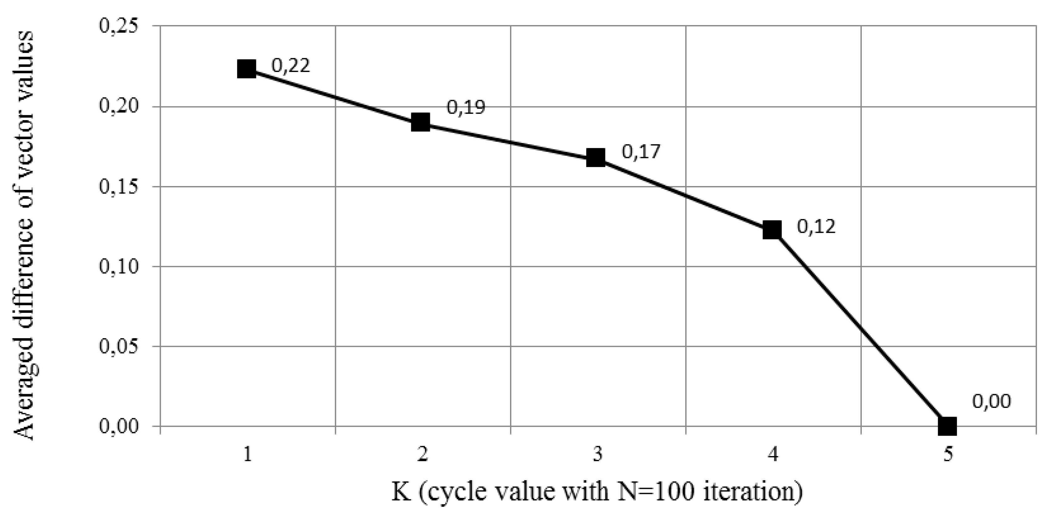
4.4. Modeling Results
To demonstrate the convergence of the method, independent modeling iterations were performed. In each cycle, changes in the density of the vector were recorded after calculation using Equation (6). Figure 7 present the average change value of the parameter vector while 100 independent iteration. The final decision, the value of the vector corresponds to the following composition of equipment and measures: the application of monitoring the condition of the pump windings, and the emergency opening of the drain valve. Vector B = {0, 0, 1, 0, 0, 0, 1, 0, 0} is optimal, with a total cost of S = 210, and qfire = 4.99 × 10⁻⁷ and qo.l. = 7.43 × 10⁻⁷. The results of the dynamics of the vector during updating after each modeling cycle of 100 iterations is presented in Figure 8.
5. Conclusions
This paper presents a method of bringing the problem of the optimization of a set of safety measures provided in the SIS to the problem of discrete optimization. The method of statistical modeling with significance sampling was used as a solution method. The obtained solution corresponds to the solution obtained by brute force. The obtained result can serve as a basis for the development of the requirements specification in accordance with the requirements for the life cycle of the system. Development of a risk model, including safety barriers that may prevent, control, or mitigate accident scenarios with in-depth modeling of the barrier performance allows explicit modeling of functional common cause failures (e.g., failures due to functional dependencies on a support system). The classification of safety measures is given, and the model of risk reduction based on deterministic analysis of the process is considered. It is shown that the task of changing the composition of safety measures can be represented as the knapsack discrete optimization problem, and the solution is based on the Monte Carlo method. A numerical example is provided to illustrate the approach. The considered example contains a description of failure conditions, an analysis of the types and consequences of failures that could lead to accidents, and a list of safety measures. Solving the optimization problem used real reliability parameters and cost of equipment. Based on the simulation results, the optimal composition of safety measures providing cost minimization is given. For the future research, the authors plan to take into account the dynamic change of the system, e.g., under cyberattacks which aim to compromise the safety features of the system.
Author Contributions
Conceptualization: V.B.; methodology: A.M.; writing—original draft preparation: A.M.; writing—review and editing: A.M.; visualization: A.M. All authors have read and agreed to the published version of the manuscript.
Funding
This research received no external funding.
Conflicts of Interest
The authors declare no conflict of interest.
References
- IEC. IEC 61511 Functional Safety–Safety Instrumented System for the Process Industry Sector; IEC: Geneva, Switzerland, 2003. [Google Scholar]
- IEC. IEC 61508 Functional Safety of Electronical/Electrical/Programmable Electronic Safety-Related Systems; IEC: Geneva, Switzerland, 2012. [Google Scholar]
- Bogatyrev, V.A. On interconnection control in redundancy of local network buses with limited availability. Eng. Simul. 1999, 16, 463–469. [Google Scholar]
- Habibullah, M.S.; Lumanpauw, E.; Kolowrocki, K.; Soszynska, J.; Ming, N.G. A computational tool for general model of industrial systems. Operation processes. Electron. J. Reliab. Risk Anal. Theory 2009, 2, 181–191. [Google Scholar]
- ISO 12100 Safety of machinery — General principles for design — Risk assessment and risk reduction Safety of Machinery-Basic Concepts, General Principles for Design-Part 1: Basic Terminology, Methodology; ISO: Geneva, Switzerland, 2010.
- Hale, A. Note on barriers and delivery systems. In Proceedings of the PRISM Conference, Athens, Greece, 15–17 September 2003. [Google Scholar]
- Kecklund, L.J.; Edland, A.; Wedin, P.; Svenson, O. Safety barrier function analysis in a process industry: A nuclear power application. Ind. Ergon. 1996, 17, 275–284. [Google Scholar] [CrossRef]
- Delvosalle, C.; Fievez, C.; Pipart, A. Accidental Risk Assessment Methodology for Industries in the context of the Seveso II directive; Deliverable, D.1C. WP1—Mons; Major Risk Research Centre: Mons, Belgium, 2003. [Google Scholar]
- Svenson, O. The accident evolution and barrier function (AEB) model applied to incident analysis in the processing industries. Risk Anal. 1991, 11, 499–507. [Google Scholar] [CrossRef] [PubMed]
- ISO 14121-2 Safety of Machinery—Risk Assessment—Part 2: Practical Guidance and Examples of Methods; ISO: Geneva, Switzerland, 2012.
- IEC 62061 Safety of Machinery—Functional Safety of Safety Related Electrical, Electronic and Programmable Electronic Control Systems; IEC: Geneva, Switzerland, 2012.
- ISO 13849-1 Safety of Machinery—Safety-Related Parts of Control Systems—Part 1: General Principles for Design; ISO: Geneva, Switzerland, 2015.
- Bogatyrev, V.A.; Bogatyrev, S.V.; Bogatyrev, A.V. Model and Interaction Efficiency of Computer Nodes Based on Transfer Reservation at Multipath Routing. In Wave Electronics and its Application in Information and Telecommunication Systems WECONF; IEEE: Piscataway, NJ, USA, 2019. [Google Scholar] [CrossRef]
- Bogatyrev, A.V.; Bogatyrev, V.A.; Bogatyrev, S.V. Multipath Redundant Transmission with Packet Segmentation. In Wave Electronics and its Application in Information and Telecommunication Systems WECONF; IEEE: Piscataway, NJ, USA, 2019. [Google Scholar] [CrossRef]
- Smith., D.J.; Simpson, K.J.L. Functional Safety: A Straightforward Guide to Applying IEC 61508 and Related Standards, 2nd ed.; Elsevier Butterworth Heinemann: Oxford, UK, 2004. [Google Scholar]
- Rausand, M.; Høyland, A. System Reliability Theory. In Models, Statistical Methods and Applications; Wiley: Hoboken, NJ, USA, 2004. [Google Scholar]
- Hokstad, P.; Utne, I.B.; Vatn, J. Risk and Interdependencies in Critical Infrastructures; Springer: Berlin/Heidelberg, Germany, 2012. [Google Scholar]
- Andonov, R.; Poirriez, V.; Rajopadhye, S. Unbounded Knapsack Problem: Dynamic programming revisited. Eur. J. Oper. Res. 2000, 123, 168–181. [Google Scholar] [CrossRef]
- Martello, S.; Pisinger, D.; Toth, P. Dynamic programming and strong bounds for the 0-1 knapsack problem. Manag. Sci. 1999, 45, 414–424. [Google Scholar] [CrossRef] [Green Version]
- Martello, S.; Toth, P. Knapsack Problems: Algorithms and Computer Implementations; John Wiley and Sons: Hoboken, NJ, USA, 1990. [Google Scholar]
- Kroese, D.P.; Taimre, T.; Botev, Z.I. Handbook of Monte Carlo Methods. In Wiley Series in Probability and Statistics; John Wiley and Sons: New York, NY, USA, 2011. [Google Scholar]
- Rubinstein, R.Y. Combinatorial optimization, cross-entropy, ants and rare events. In Stochastic Optimization: Algorithms and Applications; Springer: Boston, MA, USA, 2001; pp. 304–358. [Google Scholar]
- Rubinstein, R.Y.; Kroese, D.P. The Cross-Entropy Method: A Unified Approach to Combinatorial Optimization, Monte Carlo Simulation and Machine Learning; Springer: New York, NY, USA, 2004. [Google Scholar]
- IEC 60300-3-9 Dependability Management—Part 3: Application Guide—Section 9: Risk Analysis of Technological Systems; IEC: Geneva, Switzerland, 2003.
- Redutskiy, Y. Optimization of safety instrumented system design and maintenance frequency for oil and gas industry processes. Manag. Prod. Eng. Rev. 2017, 8, 46–59. [Google Scholar] [CrossRef]
- Ramírez-Marengo, C.; de Lira-Flores, J.; López-Molina, A.; Vázquez-Román, R.; Carreto-Vázquez, V.; Mannan, M.S. A Formulation to Optimize the Risk Reduction Process Based on LOPA. J. Loss Prev. Ind. 2013, 26, 489–494. [Google Scholar] [CrossRef]
Figure 1.
The relation of the design process and the safety analysis.

Figure 2.
Safety barrier classification, adopted from [7].
Figure 2.
Safety barrier classification, adopted from [7].

Figure 3.
Procedure for the development of safety barriers.

Figure 4.
Risk reduction of equipment under control (EUC) or technological process.

Figure 5.
Risk reduction of technological process.

Figure 6.
Model of risk reduction layers.

Figure 7.
Averaged difference of vector values.

Figure 8.
Dynamics of the probability vector : (A) initial state, (B) modified after 1st cycle, (C) modified after the 2nd cycle, (D) modified after the 3rd cycle, (E) final state.
Figure 8.
Dynamics of the probability vector : (A) initial state, (B) modified after 1st cycle, (C) modified after the 2nd cycle, (D) modified after the 3rd cycle, (E) final state.


Table 1.
FMEA of technological subsystem.
| Element | Failure Type | Consequences | Safety Measures |
|---|---|---|---|
| Tank | Destruction of the hull | Fire | D1-control of the hull by ultrasonic control device D2-magneto resistive monitoring device H1-switching on the fire pump and water supply H3-emergency opening of the emergency drain |
| Level sensor | False values | Exceeding the limit | D5-monitoring of the sensor Z2-emergency stop of process equipment (pump) H3-emergency opening of drain valve |
| Level sensor | The absence of values | Shutdown | not required |
| Feed pump | Feed loss | Shutdown | not required |
| Feed pump | Overheat | Fire | D3-monitoring the state of the windings D4-housing temperature control H1-switching on the fire pump and water supply |
| Feed pump | False start | Exceeding the limit | Z2-emergency stop of process equipment (pump) H3-emergency opening of drain valve |
| Transfer valve | Failure to respond | Shutdown | not required |
| Transfer valve | False opening | Shutdown | not required |
| Control system | Loss of control signal | Shutdown | not required |
| Control system | Erroneous command | Exceeding the limit | Z2-emergency stop of process equipment (pump) L1-pump control limitation when 70% of the tank volume H3-emergency opening of drain valve |
Table 2.
Dangerous failure rate
| Event | Code | FR, h−1 | α * | Probability Per Year ** |
|---|---|---|---|---|
| Tank. Destruction | qtank | 1 × 10⁻⁷ | 80% | 7.01 × 10⁻⁴ |
| Feed pump. Overheating | qPD.H | 1 × 10⁻⁵ | 50% | 4.29 × 10⁻² |
| Level sensor. False signal | qLV.F | 1 × 10⁻⁶ | 30% | 2.62 × 10⁻³ |
| Feed pump. False start | qPD.F | 1 × 10⁻⁵ | 5% | 4.37 × 10⁻³ |
| Control system. Erroneous response | qCU.F | 1 × 10⁻⁶ | 5% | 4.38 × 10⁻⁴ |
* The rejection rate was accepted in accordance with FMD-2013, ** The reliability of measures is based on the typical values of reliability of equipment intended for such tasks. The NPRD-2016 database and data on the reliability of the main manufacturers of electrical products were used as initial data.
Table 3.
Baseline data on safety measures
| # | Safety Measures | Cost, c.u. | Probability Per Year * |
|---|---|---|---|
| qD1 | Control of the body condition by ultrasonic method | 100 | 1.00 × 10⁻³ |
| qD2 | Magneto resistive monitoring device | 200 | 1.00 × 10⁻³ |
| qD3 | Control condition of winding | 10 | 1.00 × 10⁻⁵ |
| qD4 | Housing temperature control | 25 | 1.00 × 10⁻⁴ |
| qD5 | Monitoring of the sensor status by initial test | 10 | 1.00 × 10⁻⁵ |
| qZ1 | The inclusion of the fire pump and water flow | 400 | 1.00 × 10⁻³ |
| qZ2 | Emergency stop of process equipment (pump) | 200 | 1.00 × 10⁻³ |
| qZ3 | Emergency opening of the discharge valve | 200 | 1.00 × 10⁻⁴ |
| qL1 | Pump control limitation at 70% of tank volume | 5 | 1.00 × 10⁻⁴ |
* The reliability of measures is based on the typical values of reliability of equipment intended for such tasks. The NPRD-2016 database and data on the reliability of the main manufacturers of electrical products were used as initial data.
© 2020 by the authors. Licensee MDPI, Basel, Switzerland. This article is an open access article distributed under the terms and conditions of the Creative Commons Attribution (CC BY) license (http://creativecommons.org/licenses/by/4.0/).
Share and Cite
MDPI and ACS Style
Moshnikov, A.; Bogatyrev, V. Risk Reduction Optimization of Process Systems under Cost Constraint Applying Instrumented Safety Measures. Computers 2020, 9, 50. https://0-doi-org.brum.beds.ac.uk/10.3390/computers9020050
AMA Style
Moshnikov A, Bogatyrev V. Risk Reduction Optimization of Process Systems under Cost Constraint Applying Instrumented Safety Measures. Computers. 2020; 9(2):50. https://0-doi-org.brum.beds.ac.uk/10.3390/computers9020050
Chicago/Turabian StyleMoshnikov, Aleksandr, and Vladimir Bogatyrev. 2020. "Risk Reduction Optimization of Process Systems under Cost Constraint Applying Instrumented Safety Measures" Computers 9, no. 2: 50. https://0-doi-org.brum.beds.ac.uk/10.3390/computers9020050
Note that from the first issue of 2016, this journal uses article numbers instead of page numbers. See further details here.