A P4-Enabled RINA Interior Router for Software-Defined Data Centers


1
Fundació i2CAT, Software Networks Research Area, 08034 Barcelona, Spain
2
TRIA Network Systems LLC, Orlando, FL 32789, USA
*
Author to whom correspondence should be addressed.
Computers 2020, 9(3), 70; https://0-doi-org.brum.beds.ac.uk/10.3390/computers9030070
Submission received: 22 July 2020
/
Revised: 28 August 2020
/
Accepted: 31 August 2020
/
Published: 2 September 2020
(This article belongs to the Special Issue Post-IP Networks: Advances on RINA and other Alternative Network Architectures)
Abstract
:The lack of high-performance RINA (Recursive InterNetwork Architecture) implementations to date makes it hard to experiment with RINA as an underlay networking fabric solution for different types of networks, and to assess RINA’s benefits in practice on scenarios with high traffic loads. High-performance router implementations typically require dedicated hardware support, such as FPGAs (Field Programmable Gate Arrays) or specialized ASICs (Application Specific Integrated Circuit). With the advance of hardware programmability in recent years, new possibilities unfold to prototype novel networking technologies. In particular, the use of the P4 programming language for programmable ASICs holds great promise for developing a RINA router. This paper details the design and part of the implementation of the first P4-based RINA interior router, which reuses the layer management components of the IRATI Linux-based RINA implementation and implements the data-transfer components using a P4 program. We also describe the configuration and testing of our initial deployment scenarios, using ancillary open-source tools such as the P4 reference test software switch (BMv2) or the P4Runtime API.
1. Introduction
All existing implementations of the RINA architecture to date are software-based. IRATI [1] and rlite [2] are C/C++-based implementations for Linux hosts—which can also be used as low-end software routers—but are mostly focused on Linux-based servers, laptops, and virtual machines. ProtoRINA [3] is a Java-based RINA implementation, mostly designed for education purposes and quick prototyping in academic environments. Finally, RINASim [4] is an OMNeT++-based simulation framework for RINA networks.
A high-performance RINA implementation would be a great complement to the current software-based prototypes, opening the door to new use cases for RINA experimentation such as campus networks, datacenter fabrics, 5G network backhaul or communication service providers core networks to name a few; and planting the seed for future RINA-based products. It would also contribute towards lowering the perception of risk of the adoption of the RINA technology, demonstrating that RINA implementations can reach at least the same performance as equivalent implementations of legacy protocols.
One potential path towards a high-performance RINA router would be to use a fast packet I/O (Input/Output) software framework that can run on generic computer hardware, such as netmap [5] or Intel DPDK (Data Plane Development Kit) [6]. The advantages of this approach are that relatively high throughput can be provided with a great amount of flexibility—since the implementation of the software program is only bound by the constraints of computer hardware instruction sets—and the diversity in the available hardware platforms. However, depending on how intensive the processing per packet is, the CPU quickly becomes the limiting performance factor and any throughput greater than 15 Mpps per core is hard to achieve [7]. Moreover, energy consumption of compute-based routers is higher than the one of routers with specialized networking hardware.
High-performance routers usually feature dedicated hardware such as ASICs (Application Specific Integrated Circuits) that allow them to efficiently process many packets in very little time. Although usually each ASIC features an SDK (Software Development Kit) that provides a programmable environment, this programmability is usually limited by the protocols the device supports. Hence, until very recently, developing high-performance implementations for new networking protocols involved the use of FPGAs (Field Programmable Gate Arrays); which usually bring a complex development environment and have a limited hardware catalogue (e.g., the NetFPGA open-source hardware project [8] has been one of the most successful FPGA-based platforms for network research and innovation to date, since it permits rapid prototyping).
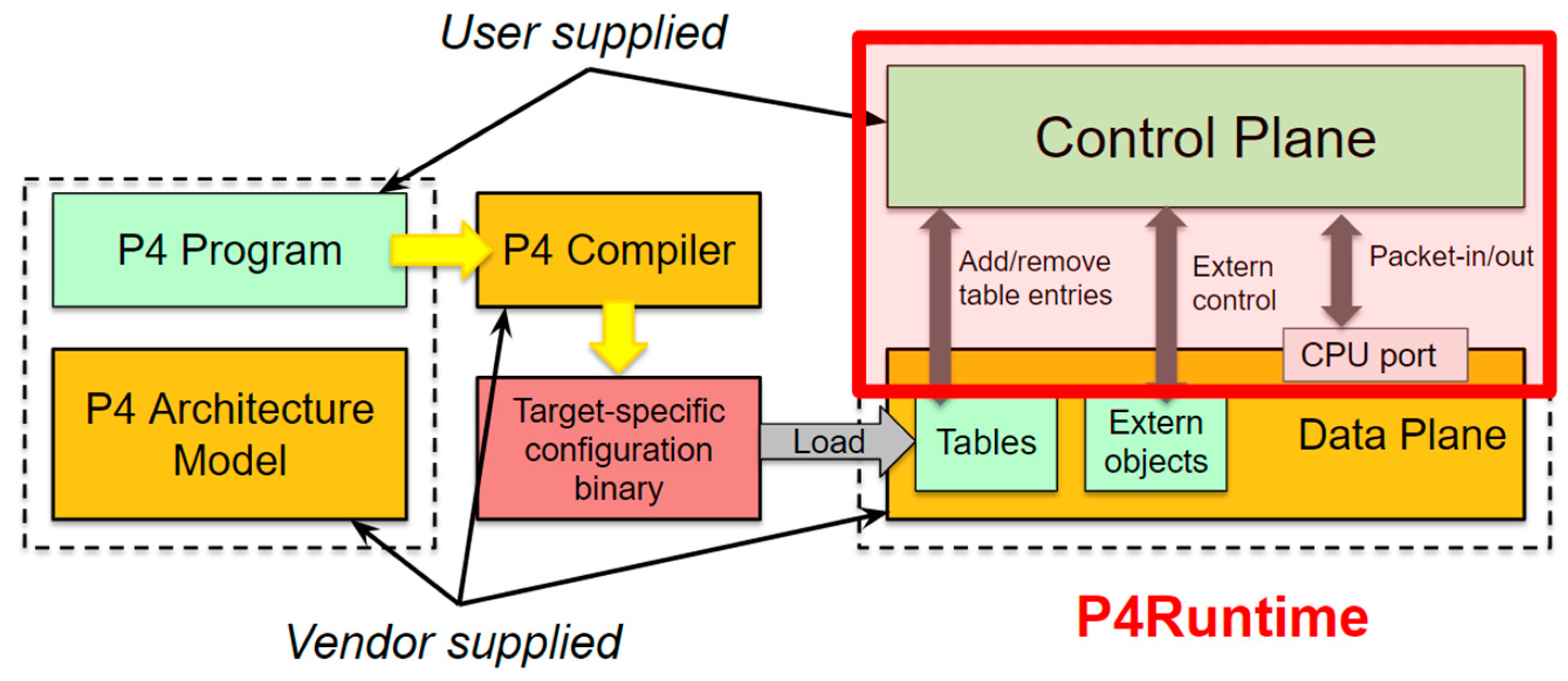
P4 [9] is an initiative designed to solve this issue, by enhancing the programmability exposed by high-performance packet forwarding ASICs. P4 is a language for expressing how packets are processed by the data plane of a programmable forwarding element such as a hardware or software switch, network interface card, router, or network appliance. P4 defines the pipeline of the target, as part of the data plane, yet it cannot be used to define the interaction between the control and data planes.
As shown in Figure 1, target manufacturers provide the hardware or software implementation framework, an architecture definition, and a P4 compiler for that target. P4 programmers write programs for a specific architecture, which defines a set of P4-programmable components on the target as well as their external data plane interfaces.
This paper presents the first implementation of a RINA interior router using P4 and leveraging on P4’s standard software switch (BMv2). The remainder of this paper is organized as follows: Section 2 discusses the use cases for a RINA router and identifies potential limitations in the P4 language that may impact their feasibility. Section 3 introduces the design and implementation of the software-based solution, with Section 4 presenting the experimental setup and discussing its evaluation in Section 5. Section 6 continues by detailing the next steps to attain the completion of the P4-based RINA interior router. Finally, Section 7 provides concluding remarks and discusses next steps for future work.
2. Use Cases: Interior and Border Routers for Agile Data Centers
The rapid growth of Cloud applications and users has caused a fast evolution in Data Center hardware and software technologies, including the networking aspects [10]. Software-Defined Data Centers (SDDC) have emerged as a concept in which the Data Center is no longer constrained by the physical location of its resources (Compute, Storage, Network), but rather by the logical connectivity between virtualized versions of such components (virtual machines, containers, logical storage volumes, virtual networks). SDDC users are given the illusion of a private, customized logical datacenter that optimally suits their needs.
SDDCs require a flexible and dynamic networking substrate that can adapt to the changing connectivity and quality requirements of different user groups, with the ability to create, span and delete virtualized networks on the fly providing different Quality of Service [11]. Several studies to date have shown that RINA-based datacenter networks provide advantages over existing networking solutions in terms of routing/forwarding scalability [12], better congestion management [13] and flexible Quality of Service support [14]. Moreover, since datacenter networks are usually private and not exposed outside of the DC boundaries, they provide an ideal environment for the deployment of new networking technologies such as those based on the RINA architecture and protocol frameworks.
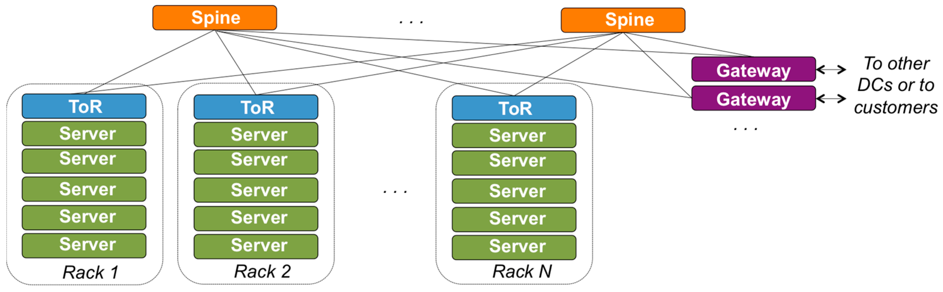
Figure 2 illustrates a simplified design of a DC, showing the physical systems and their connectivity. Servers grouped in racks provide compute or storage resources. Top of rack (ToR) routers interconnect the servers in the same rack. Spine routers provide inter-rack connectivity, and connectivity to gateways that move traffic in/out the DC towards other DCs, customer networks, or the public Internet. ToR and Spine routers are typically interconnected following a leaf-spine configuration. Large scale or hyper-scale DCs have a more complex structure, usually considering the design of Figure 2 as a module and designing the DC network as hierarchies of such modules, as shown in [12]. Nevertheless, the example of Figure 2 is enough to discuss the application of RINA in SDDCs and easier to understand, hence we will use it as is.
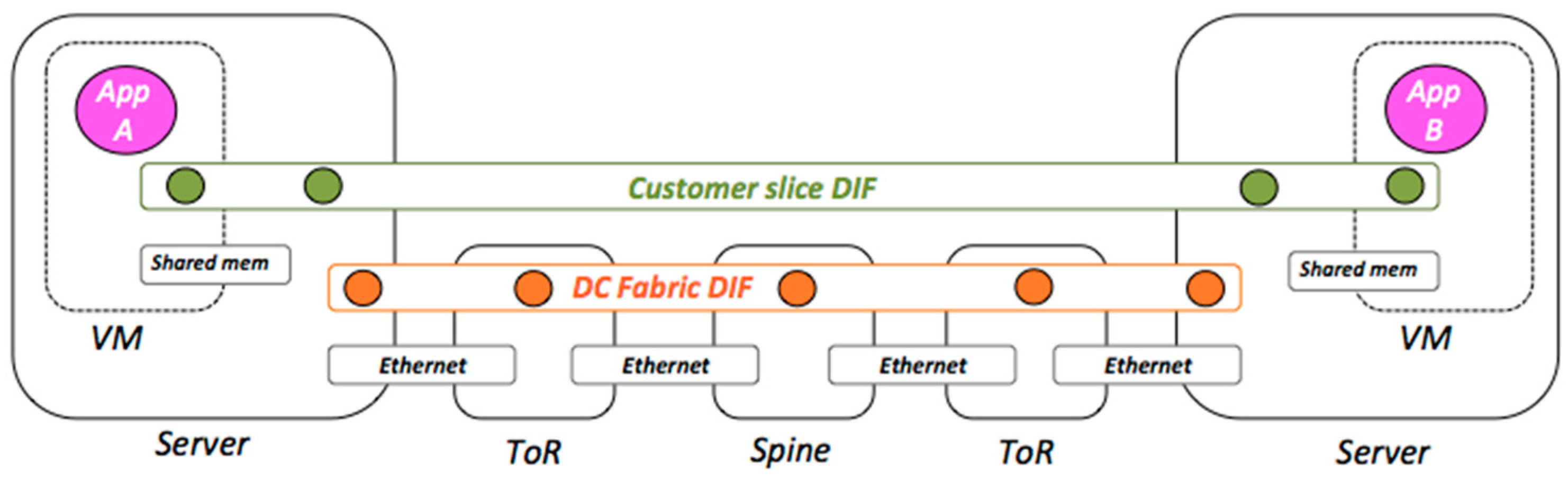
Figure 3 [15] shows a design of DIFs (Distributed IPC Facilities, the repeating layers of RINA) for the simple DC outlined in Figure 2. It depicts a Virtual Machine (VM) to VM connectivity scenario, where the rounded, black, solid rectangles represent physical systems (Computers or Routers), the horizontal rectangles represent layers of network protocols (Ethernet or DIFs), small circles represent IPC Processes (IPCPs, the instantiation of a DIF in a system), and large circles represent applications instances. All point-to-point links use Ethernet, acknowledging the fact that most Network Interface Cards (NIC) today are Ethernet-based. The Data Center Fabric DIF connects all the servers in the DC together through the ToR and Spine routers, following a leaf-spine connectivity graph. Multiple slice DIFs “float” on top of the Data Center Fabric DIF, providing a customized and private networking environment that connects together a certain number of application instances on behalf of a customer. Hence, each slice DIF can be thought of as an agile Virtual Private Network (VPN) that can be scaled up and down following the customer needs.
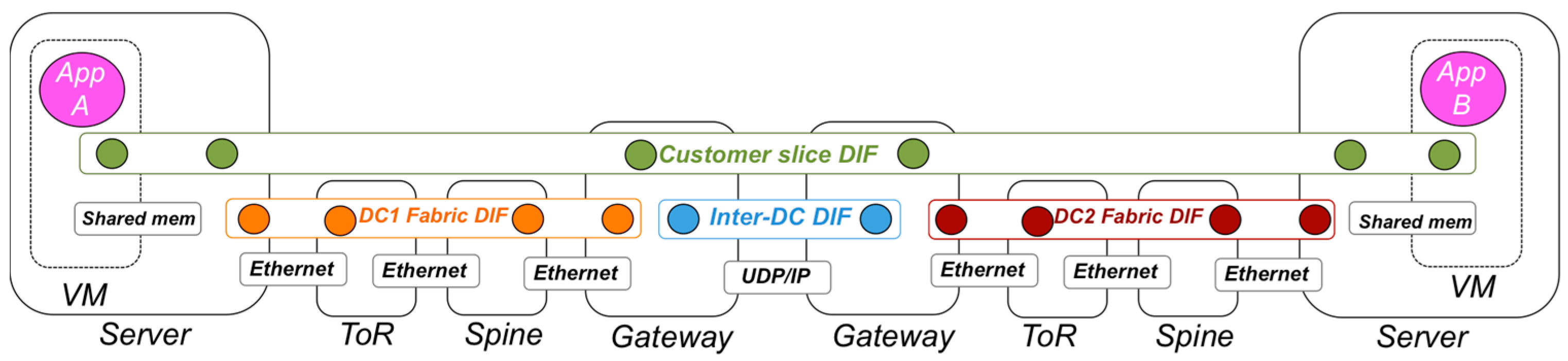
Figure 4 extends Figure 3 design into a scenario that uses two physically separated Data Centers. Each DC has its own DC Fabric DIF, and an Inter-DC DIF connects one or more gateways of multiple DCs. The Inter-DC DIF can operate over the public Internet, or over private inter-DC networks that use MPLS, Ethernet, or other networking technologies. In this scenario customer slice DIFs span multiple Data Centers, floating on top of the DC Fabric DIFs and the Inter-DC DIF.
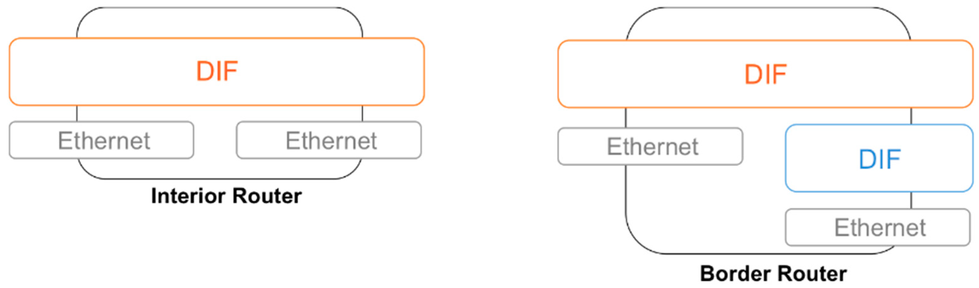
By carefully analyzing the role that high-performance RINA routers play in the SDDC configurations shown in Figure 3 and Figure 4, we come to the conclusions that there are two types of situations: one in which the RINA router just forwards data from a single DIF (as is the case of ToR and Spine routers), and another one in which the RINA router moves data up/down from a “lower DIF” before/after forwarding it on an “upper DIF” (as is the case of the Gateway Routers; we do not consider hosts because they will be typically using a software implementation, which is not the scope of this paper). We name the former configuration as interior router, and the latter as border router as shown in Figure 5.
The interior router configuration features just one “level” of DIFs on top of Ethernet interfaces, hence the router just gets the packets from the NIC, unprotects the RINA PDUs (Protocol Data Units) if needed (decrypt, integrity verification, Cyclic Redundancy Checks), checks the forwarding table and schedules it to be sent towards an output interface (protecting the PDU again if needed). The border router configuration includes two levels of DIFs, with flows on higher-level DIFs being aggregated onto “N-1” flows in lower-level DIFs. Hence the components implemented via P4 must carry out other functions such as flow termination, flow control or even retransmission control (if needed), which require keeping per-flow state.
P4 has several limitations compared to a general-purpose programming language. Some are due to the high-performance requirements of the hardware that is to be programmed, others to the short lifetime of the language and its continuous evolution. The following limitations may impact the feasibility of RINA router use case implementation, especially the border router one:
- Support for loops. There are no explicit loop or iteration constructs in P4 [16]. This is a language design choice motivated by the types of high-speed packet processing hardware architectures that are among the target platforms for P4. An indirect form of looping can be achieved by using the resubmit (invoked in ingress, returns the packet to the parser) and recirculate (invoked in egress, returns the packet to the parser and ingress pipeline) primitives.
- Timers to fire actions. P4 does not support timers by default, unless a specific target provides a timer construct as an external module (which makes the P4 program target-dependent).
- Support for encryption. Support for encryption is delegated to target-specific external modules [16] (again making the P4 program target-dependent).
- Programming the packet scheduler (Buffering Queuing Engine, BQE). P4 does not support yet programmability of the packet schedulers, although some proposals have already been made in the academic literature [17]. Even though the BQE cannot be programmed using P4, it can be configured both directly using control plane APIs and by setting intrinsic metadata.
- Fragmentation or reassembly. P4 does not provide support to carry out fragmentation or reassembly at the data plane [18]. To carry out these functions, packets must be sent to the control plane and reinjected (introducing a significant performance penalty). The same can be said for concatenation and separation.
- No built-in support for generating new packets. A possible work-around (to e.g., generate a flow-control PDU in response to a data-transfer PDU) would be to clone the packet, modify the header values and remove the payload (can be supported by truncating the cloned packet). Further investigation with ASIC-based hardware needs to be carried out to assess the feasibility of this approach.
Having theoretically analyzed the limitations of the P4 language, the implementation of a RINA interior router with P4 seems feasible; with the caveats that it is not possible to program the scheduling algorithms used to multiplex traffic and that encryption is only available via target-dependent external modules. The feasibility of the border router use case is definitely more questionable, and even if feasible it would be quite constrained: lower DIFs would not be able to concatenate PDUs from higher DIFs, the use of recirculation as a hack to generate control packets would seriously impact performance, etc. It may be the case that the border router use case cannot be fully realized with the current P4 technology, and the use of other—more flexible but less mature—networking hardware programmability frameworks, such as the ones based on extended finite state machines, may be required [19]. Hence, the authors have decided to focus on the interior router use case for an initial Proof of Concept.
3. Design and Implementation of the Software-Based Proof of Concept
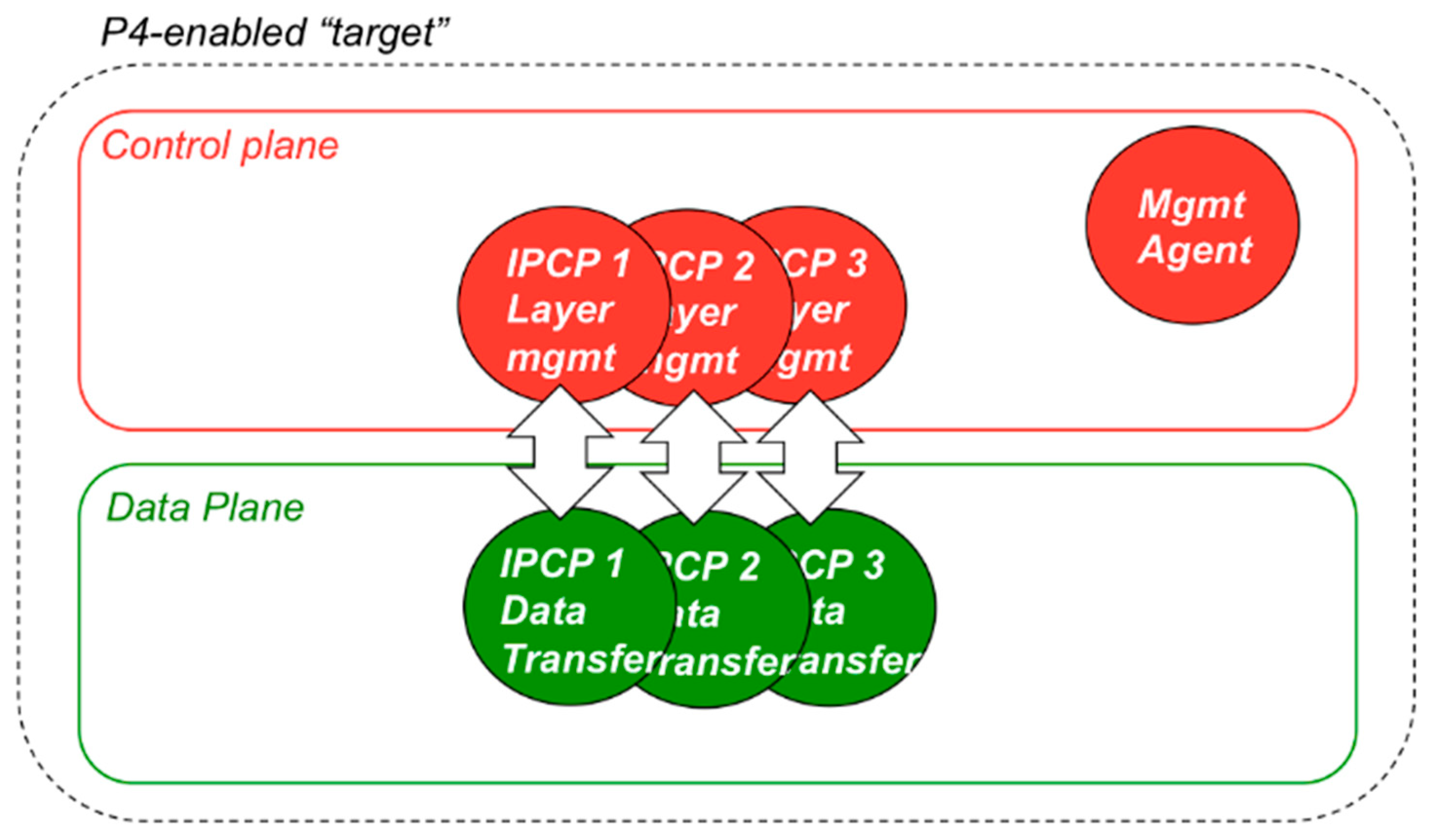
The entity that implements the DIF functionality in a given device is the IPCP. IPCPs perform several different functions, mainly divided in data-transfer control and data-transfer layer management, as shown in Figure 6. The data transfer and data-transfer control functions are performance-critical and must be implemented in the P4-enabled data plane. Such functions are executed per packet and include fragmentation/reassembly, forwarding, multiplexing, encryption, integrity protection, flow control, retransmission control, etc., while layer management functions are about the coordination of the different IPCPs in the same DIF (enrolment, authentication, access control, flow allocation, routing, resource allocation, namespace management) and can be implemented in the control plane. Finally, the Management Agent (MA) is the component that manages the lifecycle of IPCPs (creation, destruction, monitoring, (re-) configuration) and interfaces the device with the Network Management System. The MA would also be implemented in the control plane.
The Proof of Concept presented in this paper implements a complete RINA interior router pipeline using the P416 revision of the P4 language [16]. This is complemented by a control plane implemented by both a Python script and a C++-based application for interacting with the P4Runtime API. Such applications demonstrate the main interactions with the P4 data plane that would be required by a full control planed implementation: (i) loading the P4 program; (ii) adding or removing entries from the data plane tables; and (iii) sending and receiving packets from/to the data plane. The behavioral model (BMv2) software switch [20] is chosen as the target device to prototype P4 programs.
3.1. Data Plane
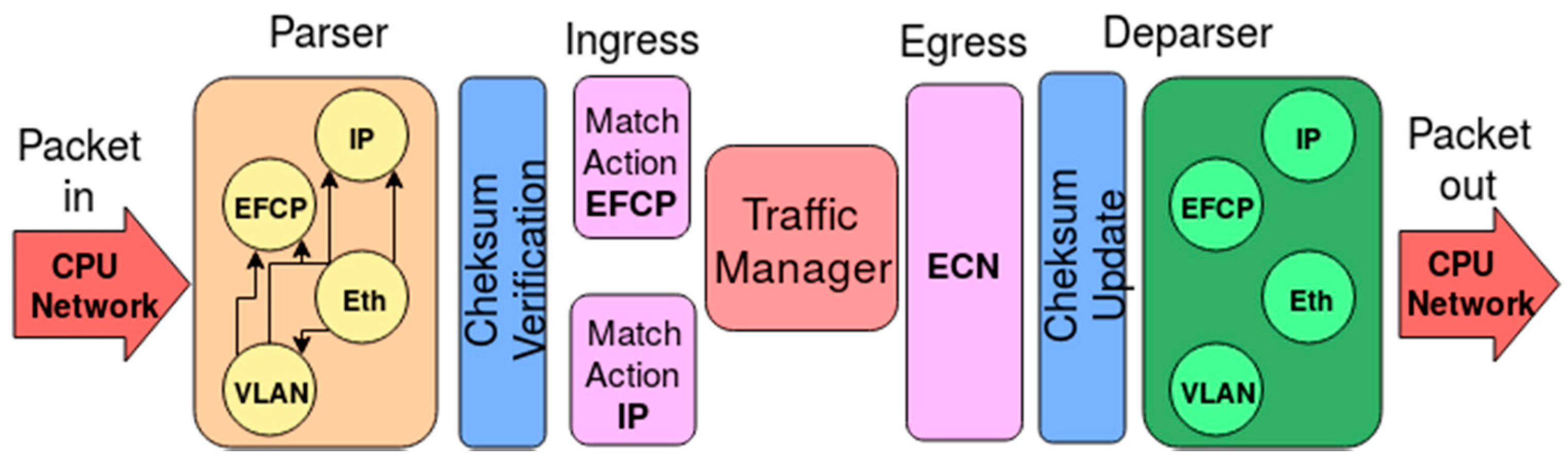
For this implementation of the RINA interior router, the v1model P4 architecture has been used on top of the BMv2 simple_switch target, a software switch developed by the P4 community for testing functionality of P4 programs. Figure 7 pictures the design of the RINA over Ethernet pipeline, as described in the following paragraphs. The pipeline supports the processing of both EFCP (RINA’s data-transfer protocol, called Error and Flow-Control Protocol) and IP packets, since it is expected that initial RINA routers would be deployed in scenarios where both RINA and IP must coexist. Since this work is an initial Proof of Concept, we have just implemented support for IPv4 packet processing, yet adding IPv6 processing capabilities to the pipeline can be done following the same approach (the parser, deparser, and match-action blocks dedicated to IP processing need to be extended).
The pipeline needs to deal with the headers that allow data transmission in different ways and layers in the Data Center: both: EFCP (RINA’s data-transfer protocol) and Ethernet, VLAN (IEEE 802.1Q) and IPv4 for the basic subset of data transmission protocols in Layers 2 and 3. The parsing and processing for other possible protocols, such as VxLAN (Virtual eXtensible Local Area Network) or IPv6 can be implemented in a similar manner, although not done out here for simplicity purposes. The logic of the pipeline starts with a programmable parser to extract the packet headers defined above. The parser supports the following protocol layering scenarios: EFCP over Ethernet, EFCP over a VLAN over Ethernet, IP over Ethernet, and IP over a VLAN over Ethernet. For simplicity, the parser assumes a single EFCP specific syntax, although multiple syntaxes can be supported easily (e.g., by associating an input interface of VLAN to a specific EFCP syntax or by checking the EFCP version number). The parser also checks the validity of the EFCP PDU types.
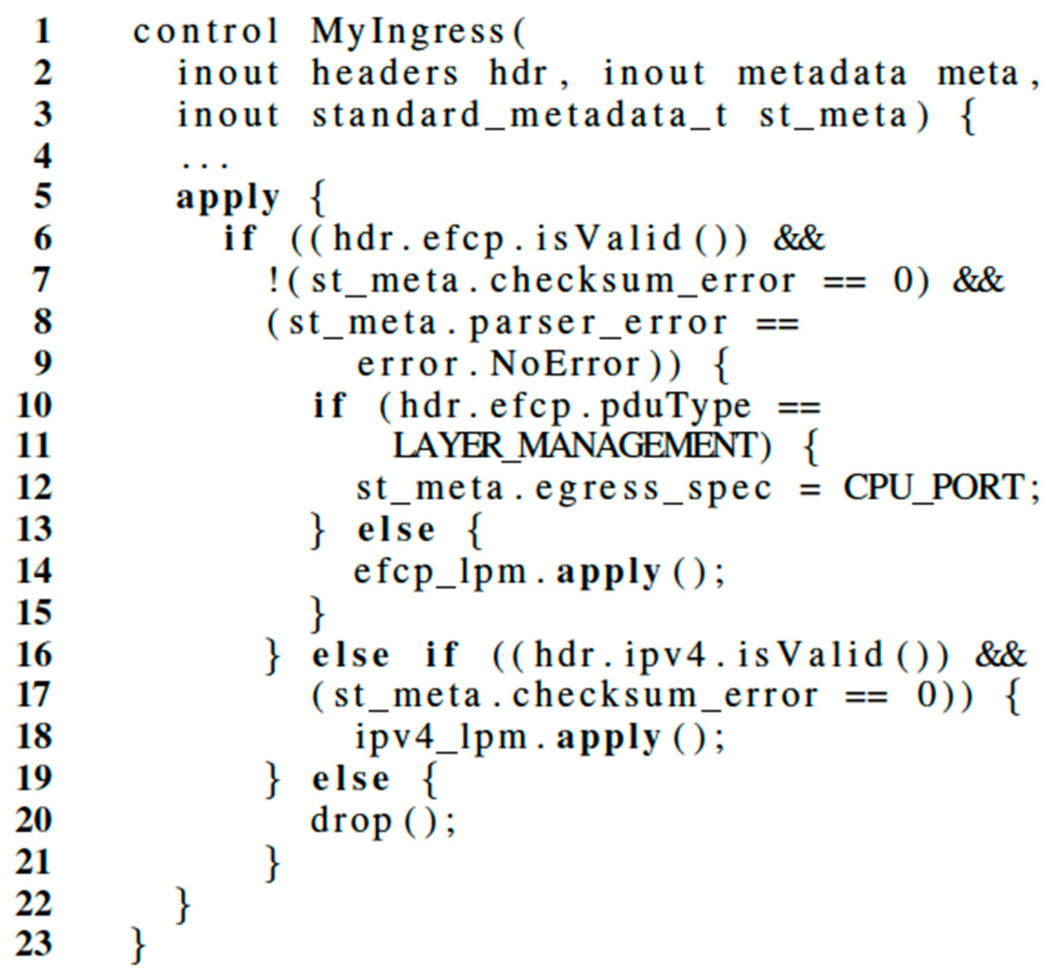
Between the parser and deparser blocks, the pipeline introduces checksum-related logic in two different blocks that either verify checksums on the incoming EFCP and IPv4 packets and update checksums on the outgoing ones. Once the checksum verification is carried out, the ingress block of match-action processing performs forwarding of IPv4 and EFCP PDUs by using, respectively, a long prefix match table and an exact match table. If the packet matches no entries in the table it is dropped; otherwise the packet is validated for correctness and sent according to the specific table entry that dictates the processing for its given type. Besides that, an EFCP PDU is sent to the control plane of the router if its type is layer_management. Pseudocode for specific ingress packet processing logic is provided in Figure 8.
Right after ingress packet processing, an egress block of match-action processing allows the P4 program to modify a packet based on the port it is departing from. This block takes care of providing congestion control information by using the Explicit Congestion Notification (ECN) flag to mark the EFCP packets that have experienced queue occupancy higher than a given (configurable) threshold X of PDUs while being processed by the Traffic Manager.
At the end of the pipeline, the programmable deparser reconstructs the packet as specified in the P4 program. The deparser supports the same protocol layering as the parser, but it is not tied by the input layering: the router may get an EFCP packet over Ethernet without VLANs on one side and produce an EFCP packet over a VLAN over Ethernet on the output side; and vice versa. The same applies to the IP packet processing pipeline.
3.2. Control Plane
The interaction with the data plane is achieved through P4Runtime, a control plane specification defined by the P4 consortium for runtime control of P4 targets which achieves independent communication between the P4 program (protocol) and the target. The P4Runtime API [21] enables (i) specifying and loading a specific pipeline P4 program; (ii) sending and receiving packets and notifications; and (iii) reading and writing the forwarding table entries, counters, and other chip features. The target device must provide an implementation of the P4Runtime API to support P4 programmability. Such implementation leverages on gRPC (Google Remote Procedure Call) methods, defined as generic protobuf (Google Protocol Buffers) data structures. Through the gRPC bindings for languages such as C++, Python, and Go, these structures are used to automatically generate wrappers from interfaces that enable communication between a client and the specific server in different languages. The P4Runtime API exposes the following methods:
- Write: adds or updates one or more entities on the target, then returns a single response.
- Read: fetches one or more entities from the target and returns as many responses as entities requested.
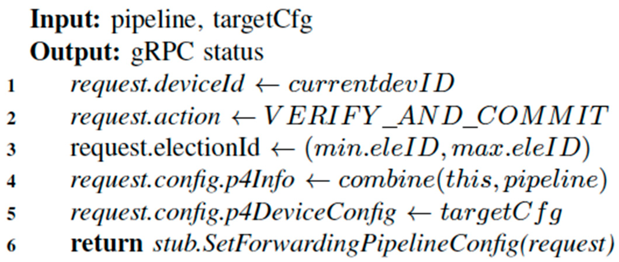
- SetForwardingPipelineConfig: uploads the P4 pipeline configuration (via the P4 program and the target configuration), then returns a single response.
- GetForwardingPipelineConfig: gets the current P4 forwarding pipeline configuration (as defined previously by the above method), then returns a single response.
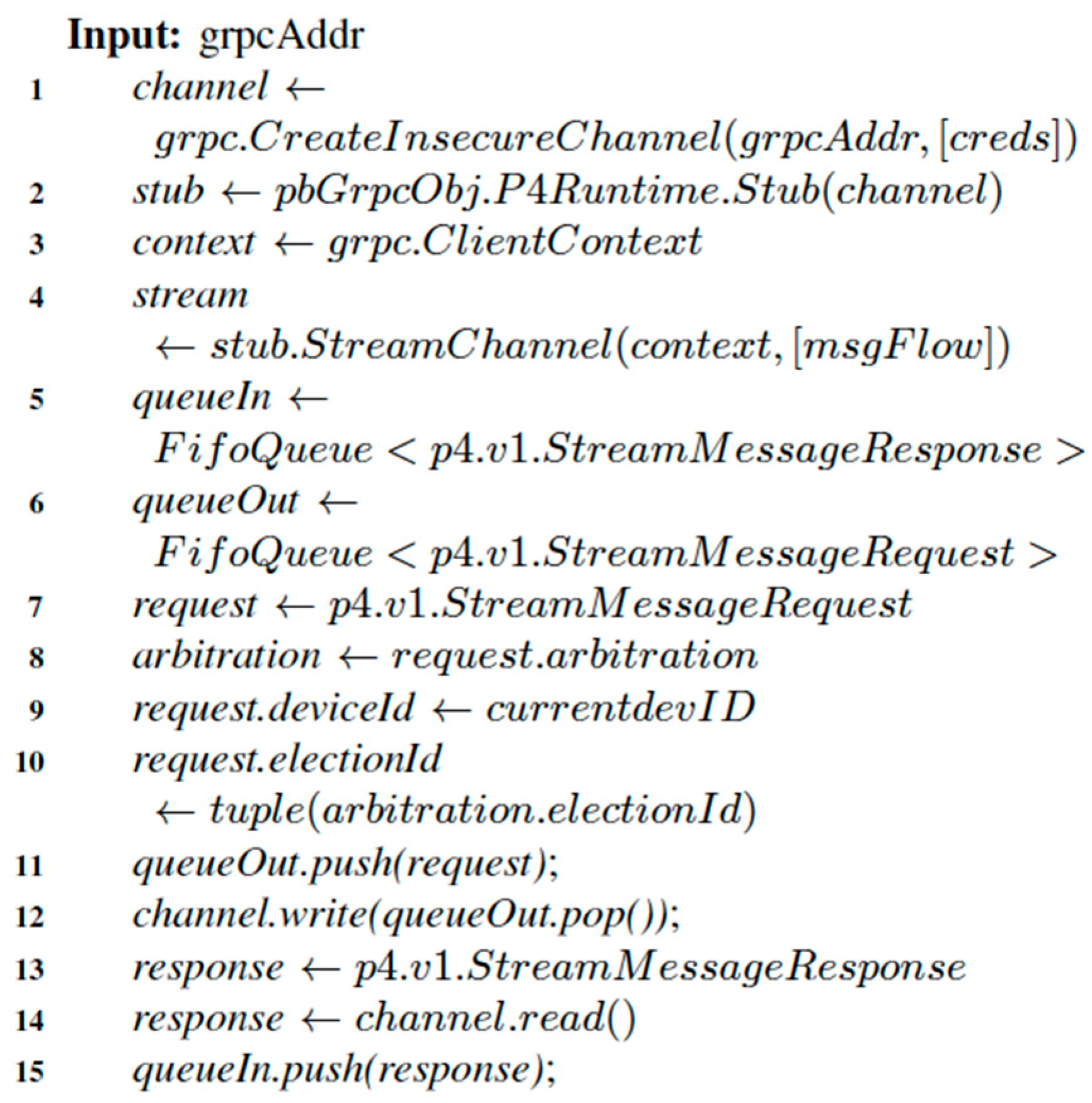
- StreamChannel: models the bi-directional stream between controller and target, where multiple requests and responses can occur at any point. This is used to first setup such connectivity through the arbitration that decides when and how each component can connect by means of consensus algorithms, as well as to indicate when the session is live; but also to stream notifications from the target and the bi-directional communication of packets to/from the target.
- Capabilities: requests data for a single capability (e.g., API version) and returns a single response.
Depending on the language of choice, the signature of the implemented methods will change, greatly impacting the workflow. An example of this is that as opposed to the Python bindings, the StreamChannel constructor in the C++ bindings does not expect an iterator on incoming messages and requires a stricter control when reading from the incomings stream. As defined above, the StreamChannel method—disregarding implementations specific to each language—is used in the crucial stage of establishing the bi-directional session from the client (controller) to the server in the target (determined by “grpcAddr” in Figure 9). The handshake process negotiates first the arguments of the session with the target. Among them, the arbitration mechanism determines whether the controller is master or slave, i.e., it has write or read permissions. Once the session is up, the controller must handle ingress response and egress request messages towards the target, for instance by using a couple of FIFO (First In First Out) queues. Figure 9 provides a rough approach to this step, although the specifics will change considerably depending on the options provided by each gRPC binding.
After properly establishing the session between the client in the controller and the server in the target device, the SetForwardingPipelineConfig method can push the pipeline (definition of the program) and the configuration of the target configuration, as determined by “pipeline” and “targetCfg” in Figure 10.
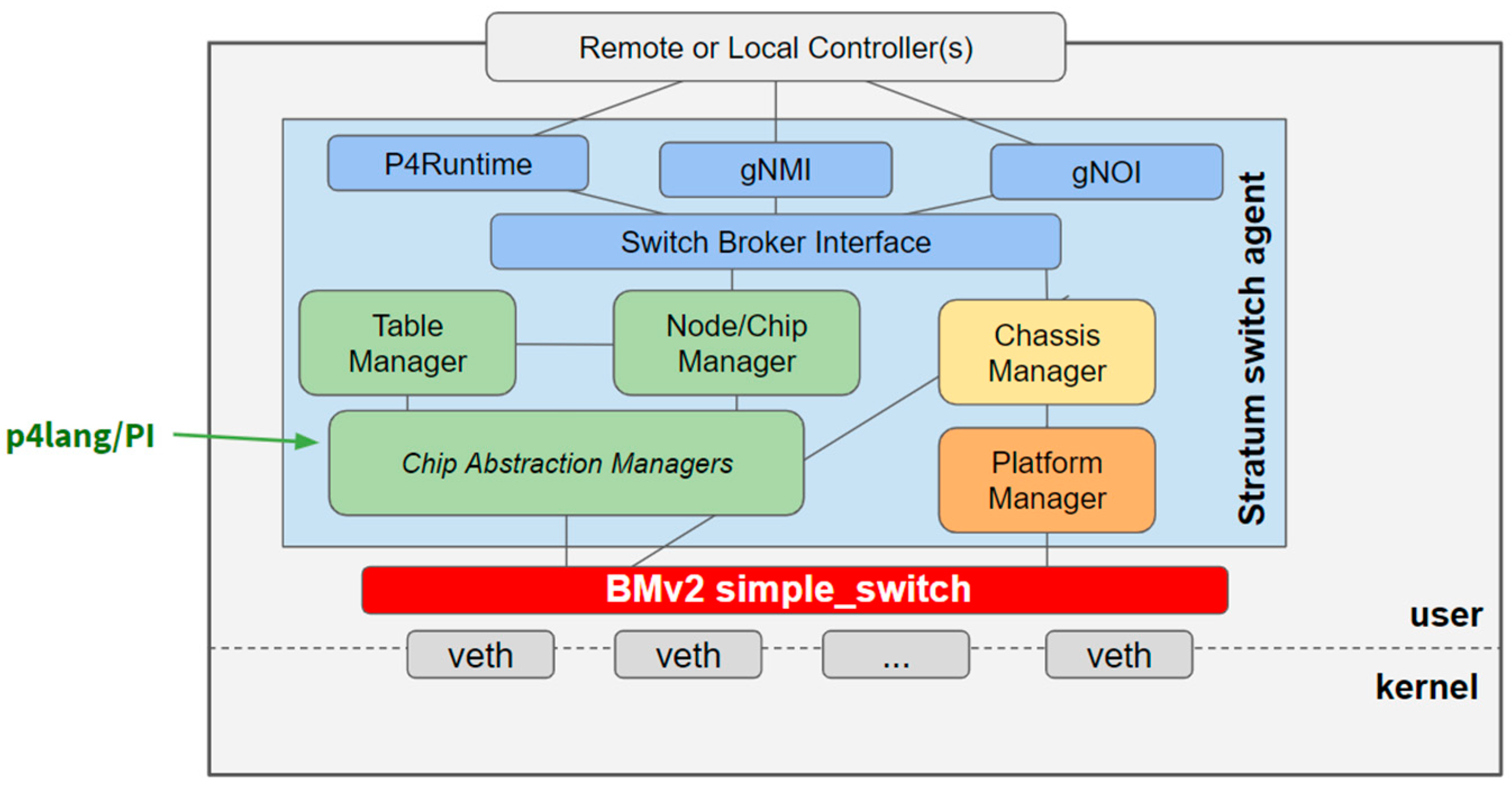
Given that the RINA P4 implementation must be able to configure, control, and program the pipeline of P4-enabled white box devices, we need a simple Network OS (Operating System) that enables easy integration of P4Runtime into the targets, and that also provides the usual hardware management, configuration, and monitoring facilities. Stratum [22] is an open-source, production-targeted, thin switch OS developed by the Open Networking Foundation (ONF) and Google that fits well with this use case, as it exposes next-generation software-defined networking interfaces and models such as P4Runtime API to enable interactions with the P4 data plane. Figure 11 shows a simplified view of Stratum’s architecture for the BMv2 simple_switch target device.
Generally speaking, Stratum enables model-driven management and operations via the gNMI (gRPC Network Management Interface) and gNOI (gRPC Network Operations Interface) interfaces, providing declarative device configuration and streaming telemetry capabilities. Moreover, Stratum has drivers to support hardware from multiple vendors, including Barefoot Tofino. Hence, the control plane developed for the BMv2 software switch can be later reused for hardware-based, P4-capable targets with minimal changes. In our initial implementation, Stratum runs on top of BMv2 and implements P4’s v1Model architecture with Stratum APIs over gRPC.
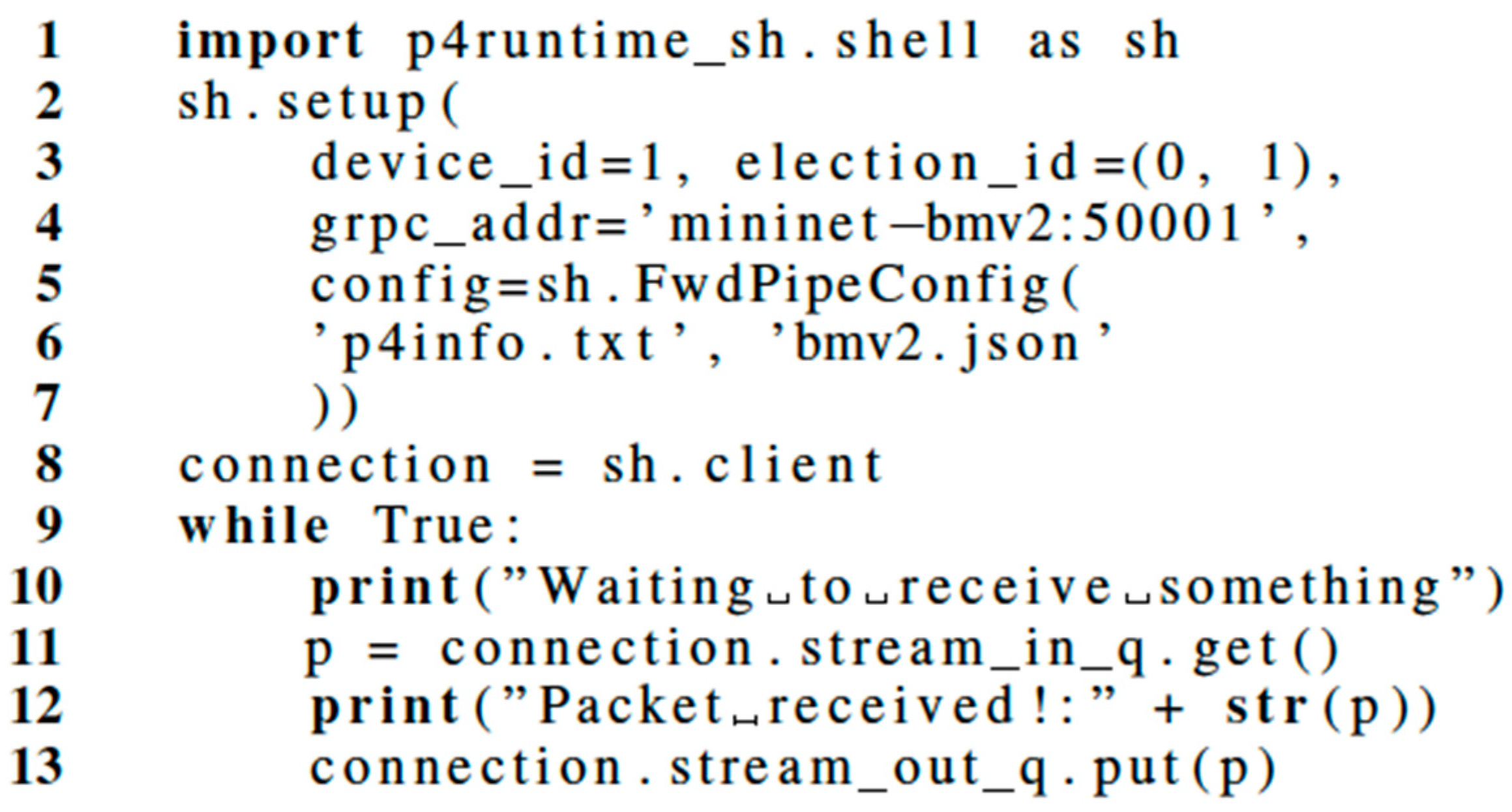
We initially used P4Runtime-Shell [23] as the control plane for our PoC (Proof of Concept). P4Runtime-shell is a Python tool that interacts with the P4 Runtime API via an interactive shell. It starts by opening a session with the P4 Runtime API gRPC server and immediately loading the pipeline with the EFCP program. Once the session is established, the match-action table entries can be sent on real time to the target via the interactive console provided by P4Runtime-Shell. The format is shown in Figure 12.
The data plane is now configured, and the data transmission can start. The control plane listens for PACKET_IN events (EFCP PDU coming from the data plane), logs the PDU contents and sends the PDU back to the data plane. The source in Figure 12 documents how to use P4Runtime-Shell to setup the session and then monitor the sending and receiving of EFCP PDUs from/to the data plane. An infinite loop can serve to monitor each packet from the ingress queue, print its contents, and finally push it to the egress queue so that is ready to be processed and forwarded.
After validating the Python PoC, we developed a C++-based control plane, which broadly implements the same P4Runtime interfaces as those exposed by P4Runtime-Shell and which makes it possible to directly integrate and interact with the control plane to feed it with adequate data. As described in Section 6, the layer management components of the IRATI RINA implementation will be able to directly integrate and interact with this implementation of the control plane to feed it with adequate data.
4. Setup of the Software-Based Solution
Both the experimental and the extended scenarios leverage on the use of Docker containers, as a more portable and cleaner setup that can run indistinctly in a developer’s machine and in the remote integration nodes.
In both setups, Mininet has been used to build virtual networks and to interact with them using the Mininet Command Line Interface (CLI) or API. A realistic virtual network is created, running a real kernel, switch and application code, on a single machine (virtual or physical). The Mininet Python API bindings simplify the way to create a flexible scenario that can be configured based on the parameters passed into it and can be run as a program—for instance, as part of a test. Another advantage of Mininet is that the hosts share the root file system of the underlying machine. Internally, Mininet employs lightweight virtualization features in the Linux kernel, including process groups, CPU bandwidth isolation, as well as network namespaces, and combines them with link schedulers and virtual Ethernet links. These features yield a system that starts faster and scales to more hosts than emulators that use full virtual machines.
4.1. Experimental Setup
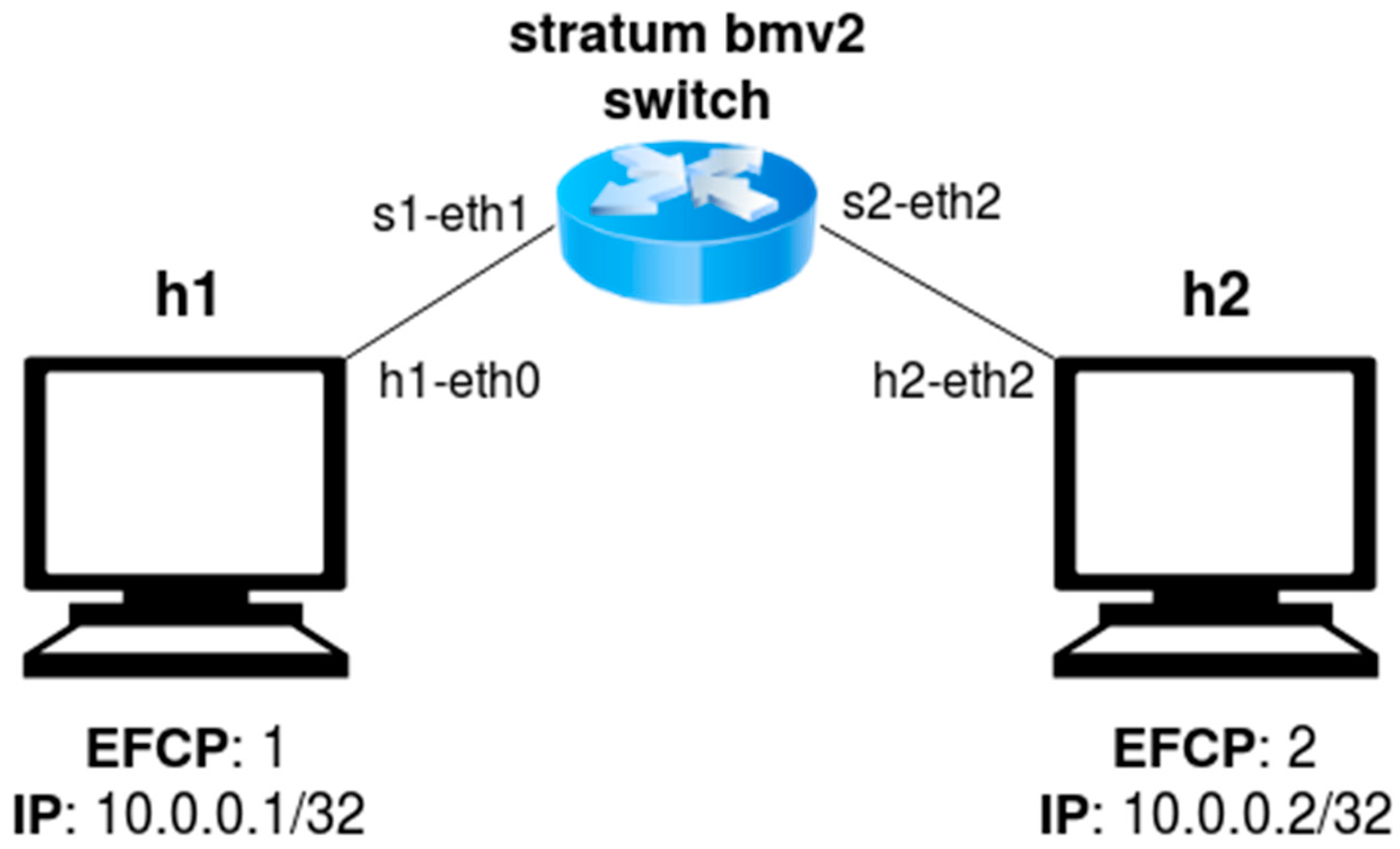
The first Docker container hosts a containerized version of the open-source P416 compiler, which includes a backend for the BMv2 software switch target named p4c-bm2-ss. The compiler generates two files, which are later used by the control plane when invoking the SetForwardingPipelineConfig method. The first file, called bmv2.json, defines a configuration for the BMv2 simple_switch target in JSON (JavaScript Simple Object Notation) format. When the switch target receives a new packet, it uses this configuration to process the packet in a way that is consistent with the P4 program. The second file, called p4info.txt, contains an instance of a P4Info schema for our P4 program, describing the match-action tables that are exposed via the P4Runtime API. The second Docker container creates a Mininet emulated network of a BMv2 switch running Stratum and the EFCP pipeline presented in Section 3.1, interconnecting two hosts as depicted by Figure 13. Each host can generate EFCP and IP packets, and is directly connected to the BMv2 switch via a single interface.
4.2. Extended Setup
The extended setup also establishes, in a first stage, a virtualized environment interconnecting a similar BMv2-enabled Mininet configuration and the P4Runtime client. The second stage requires the installation and configuration of the hardware environment that is interconnected and where the P4 program and the P4Runtime client will run.
The first Docker container is dedicated to provisioning a specialized virtual environment that automatically installs the protobuf and gRPC libraries, as well as other dependencies. It then downloads the P4Runtime specification and compiles the protobuf files using the C++ bindings. This generates several classes that implement the data structures and methods defined by P4Runtime, such as the so-called service stub: an interface class that is used by the client to interface with the RPC (Remote Procedure Call) methods exposed by the server. With this environment set up and connected to the same network as the second container, the P4Runtime gRPC client can be executed.
On the other hand, the second container runs the same Mininet network as depicted in Figure 13. Thus, the client can connect to the P4Runtime API in the server exposed by the simple_switch inside this container.
4.3. Production Setup
While the scenarios described above are virtualized, the final deployment setup consists of physical P4-enabled hardware that runs in a remote datacenter. Figure 2 illustrates the deployment setup that is to be used in the production environment.
Each target to be managed via P4 shall be reachable by the Stratum NOS (Network Operating System), which must be also reachable from the controller that will host the control plane of each target. However, before Stratum can be installed, an operator must follow a set of steps, as described in the Stratum documentation. Depending on the ASIC vendor and the model of the target, this may require more steps.
First, ONLPv2—a special branch of the Open Network Linux (ONL) distribution—must be installed on the target device, which must have the Open Network Install Environment (ONIE) pre-installed, as that is the bare minimum to install any software on top. ONLPv2 may be then built from scratch or downloaded from the fork maintained by ONF. The ONIE boot loader will detect the NOS installed after following one of the available methods, and the installed ONL will be the OS of reference from now on in the target device. Nevertheless, the installation procedure is ASIC-dependent, so for instance a Tofino-based target can use the alternative of installing the Board Support Package (BSP). At this point, Stratum should be run on a separate server to generate a target-specific binary. Certain flags can be used to customize the binary, such as using the interfaces provided by ONLPv2 to access the Physical Hardware Access Layer (PHAL), as well as providing the version of “P4Studio”, the Software Development Environment (SDE) in case of a Tofino ASIC.
Finally, the binary generated via Stratum must be placed in the target device. Depending on the target platform, the binary can be a stand-alone package that is directly executed on the switch or it may require providing a dynamic array of arguments in the form of configurations, such as the base and specific chassis configuration (definition of the chip capabilities and all possible port configurations, for the base configuration, or the subset of the available ones, for the specific configuration) and other files for different chip-specific properties (such as Access Control Lists—ACLs), as well as files that describe vendor-specific environments that can provide further configuration. When the Stratum binary is running on all different silicon targets, these should become reachable from any of the connected servers. A control plane binary running on such machines should be able to connect to each of the ASICs.
5. Evaluation of the Software-Based Proof of Concept
We now proceed to document the evaluation of the connectivity and performance of the experimental setup. As a next step, once the extended and production setups are fully configured and available, further tests will be performed.
5.1. Connectivity Tests
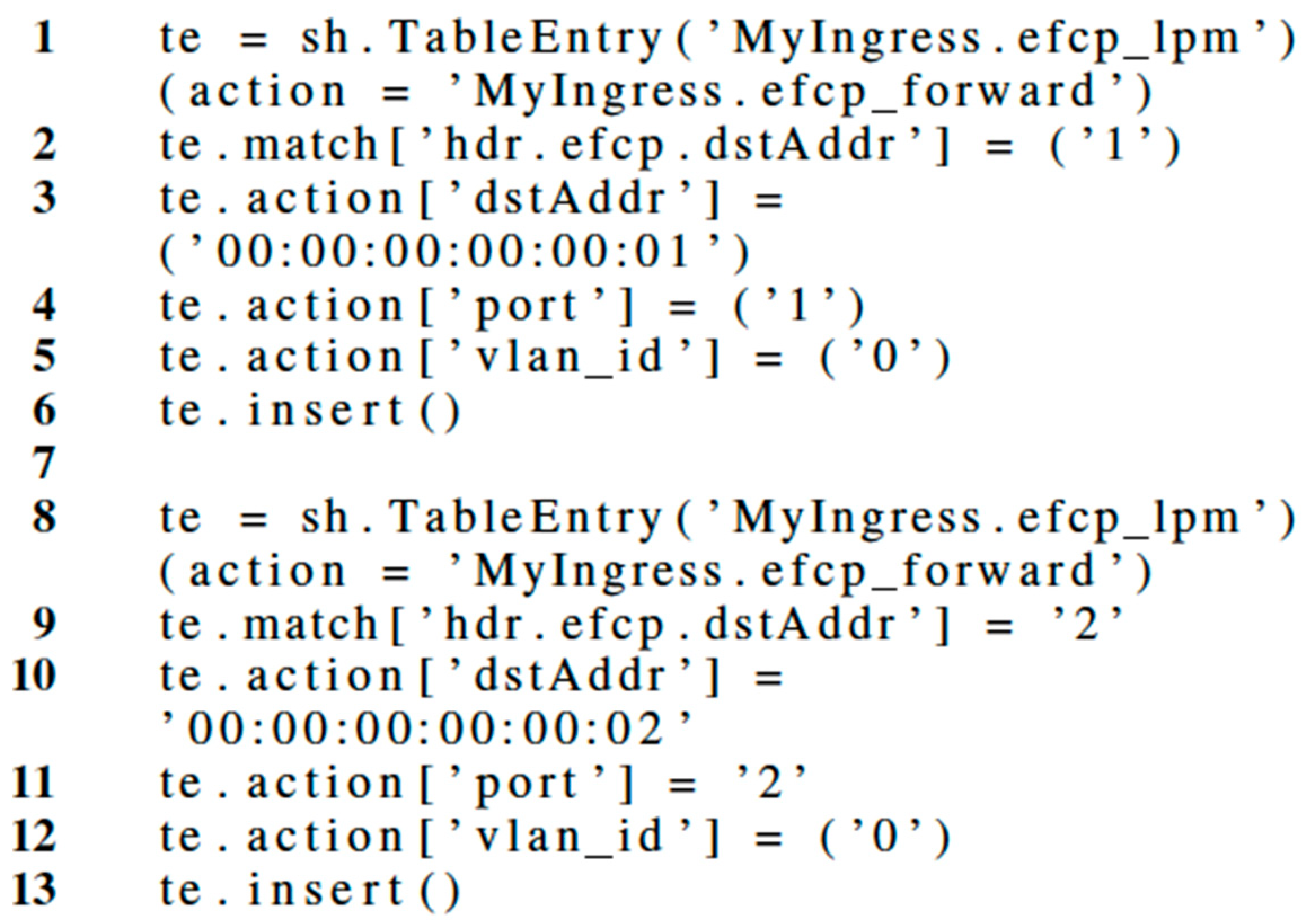
Having set up the experimental scenarios using Mininet, we proceeded to validate the functionality of the P4 program via initial connectivity tests. First, the P4Runtime-Shell framework is used to populate the data plane tables of the BMv2 simple_switch with adequate forwarding instructions, as documented in Figure 14.
Once the connectivity was set up, a simple packet generator was implemented with the Scapy tool. Scapy is a Python framework that enables users to send, sniff, dissect, and forge network packets among other features. It can be used as an interactive Python interpreter or imported as a Python module and used for further coding. The main advantage of using this framework is that it facilitates the generation of packets for any type of protocol and allows the transmission and reception of such packets via the desired network interfaces. We have created Scapy scripts to generate EFCP packets encapsulated over Ethernet—with and without VLANs—to test the different configurations supported by the EFCP P4 data plane. We have also created equivalent scripts to send and receive IP packets, validating the basic functionality of the hybrid EFCP/IP P4-based router executing in the BMv2 simple_switch target device. Connectivity tests have performed well and verified the functionality of the EFCP/IP RINA interior router in a variety of configurations.
5.2. Performance Tests
After the successful execution of connectivity tests, we have decided to stress the system a bit more with a set of performance tests. We are aware that BMv2 is not meant to be a production-grade software switch but designed as a tool for developing, testing, and debugging P4 data planes and control plane software written for them. As such, the performance of BMv2—in terms of throughput and latency—is significantly less than that of a production-grade software switch such as Open vSwitch. Performance is also very inconsistent and depends on a variety of factors such as the logic of the P4 program under execution, the P4 compiler used, the BMv2 version, the flags used to build BMv2, the number of data plane table entries, the characteristics of the hardware where the software is running (e.g., CPU cores, how much CPU cache, etc.), or whether the scenario is running on a bare-metal Linux machine or a Virtual Machine.
Despite BMv2 just being a development and testing tool, performance tests are still a useful way to make sure there are no hidden issues in our P4 program that did not surface during the connectivity tests. They are also a good way to understand what the performance limitations of BMv2 are and hence what the limits are to the scenarios that can be tested using this tool.
A custom C program was developed as a performance testing tool. The program accepts a network interface name, which is used to send or receive Ethernet packets encapsulating EFCP or IP PDUs. The client mode of the program sends a continuous flow of IPv4 or EFCP packets through the specified network interface with the desired packet length, optionally pausing a certain number of microseconds between each packet write event. The server mode of the program binds to the network interface and receives all Ethernet packets, measuring the throughput achieved by the transmission.
We have run the performance tests using two different resource configurations. The first one features a Linux VM with 2 GB of RAM and 2 CPU cores. The tests have been done with the BMv2 simple_switch_grpc component configured without logging macros. The second configuration is based on an Amazon Web Services (AWS) EC2 instance (c4.2xlarge) running Ubuntu server with 8 CPU cores and 15 GB of RAM. Tests have been carried out with the BMv2 simple_switch configured with optimization flags and without logging macros. All Ethernet links are virtual links that connect virtual interfaces within the same server; hence we are only evaluating the performance of the P4 pipeline implemented via the BMv2 model.
5.2.1. Local Virtual Machine Scenario Results
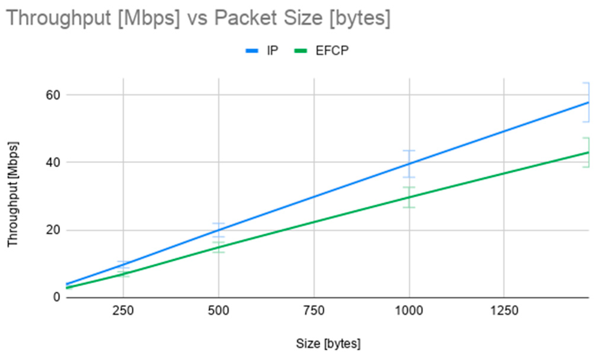
Figure 15 shows the throughput measured by the custom C application in Mbps, as a function of the packet size in bytes. The green line represents the average results of 10 tests with IP packets, while the blue line represents the average result of 10 tests with EFCP packets. As expected, the throughput is quite low (limited to around 60 Mbps) and slightly higher for the IP tests. The lower performance of the EFCP packet processing pipeline from the prototype is due to a few more steps and validations: checking for valid PDU types, parsing and generating VLAN headers, marking packets with the ECN flag. Packet length in the throughput tests varies from 250 bytes to 1470 bytes.
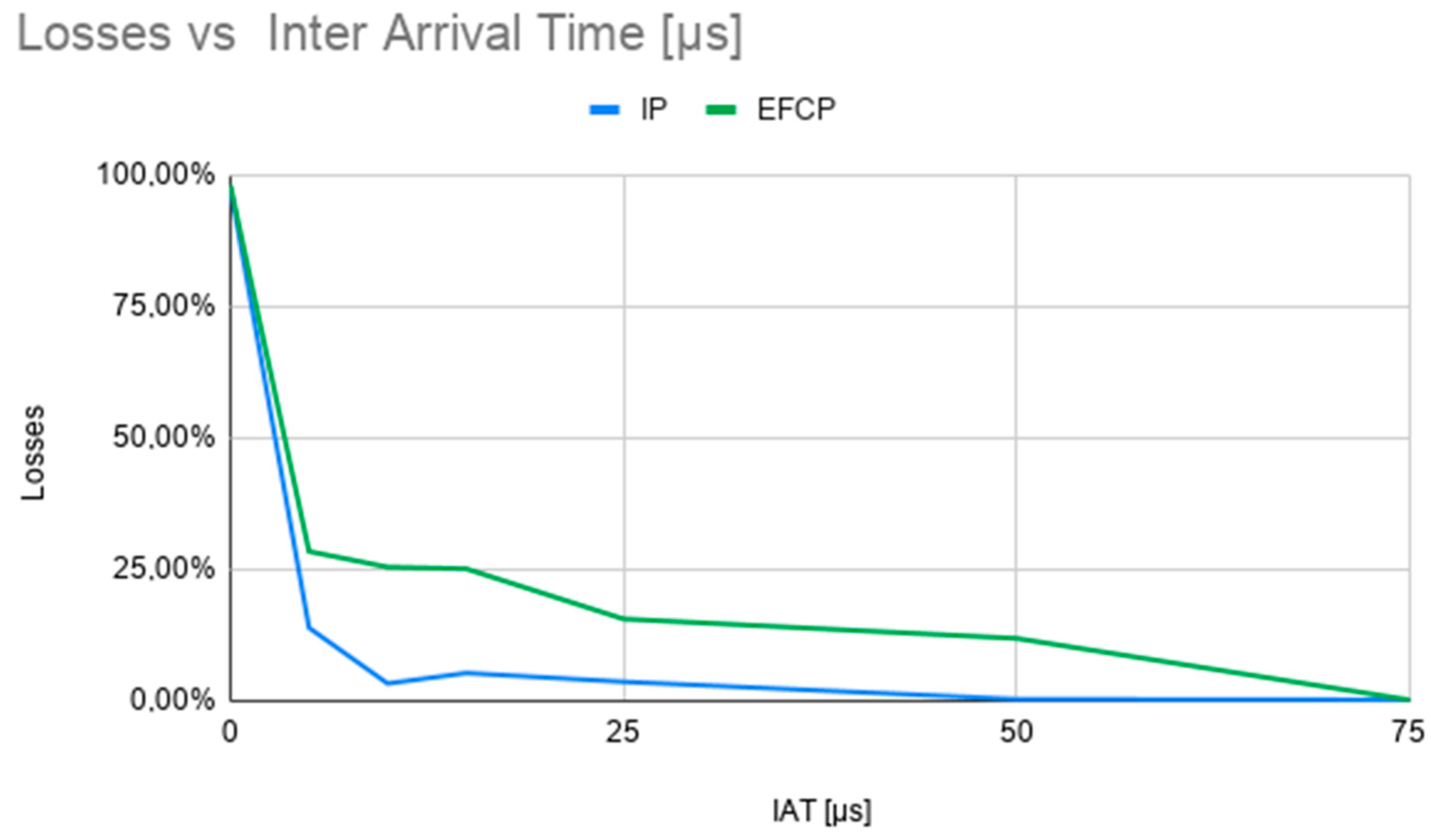
Figure 16 shows packet loss measured at the P4 router’s input interface, as a function of the inter-arrival time of the packets generated by our test program, with a packet length of 500 bytes. As it can be seen, for inter-arrival times of less than 10 microseconds packet loss is higher than 25%, since BMv2 cannot process high volumes of traffic. Experiments performed using a different packet length show a very similar trend.
5.2.2. Amazon Web Services (AWS) Virtual Machine Scenario Results
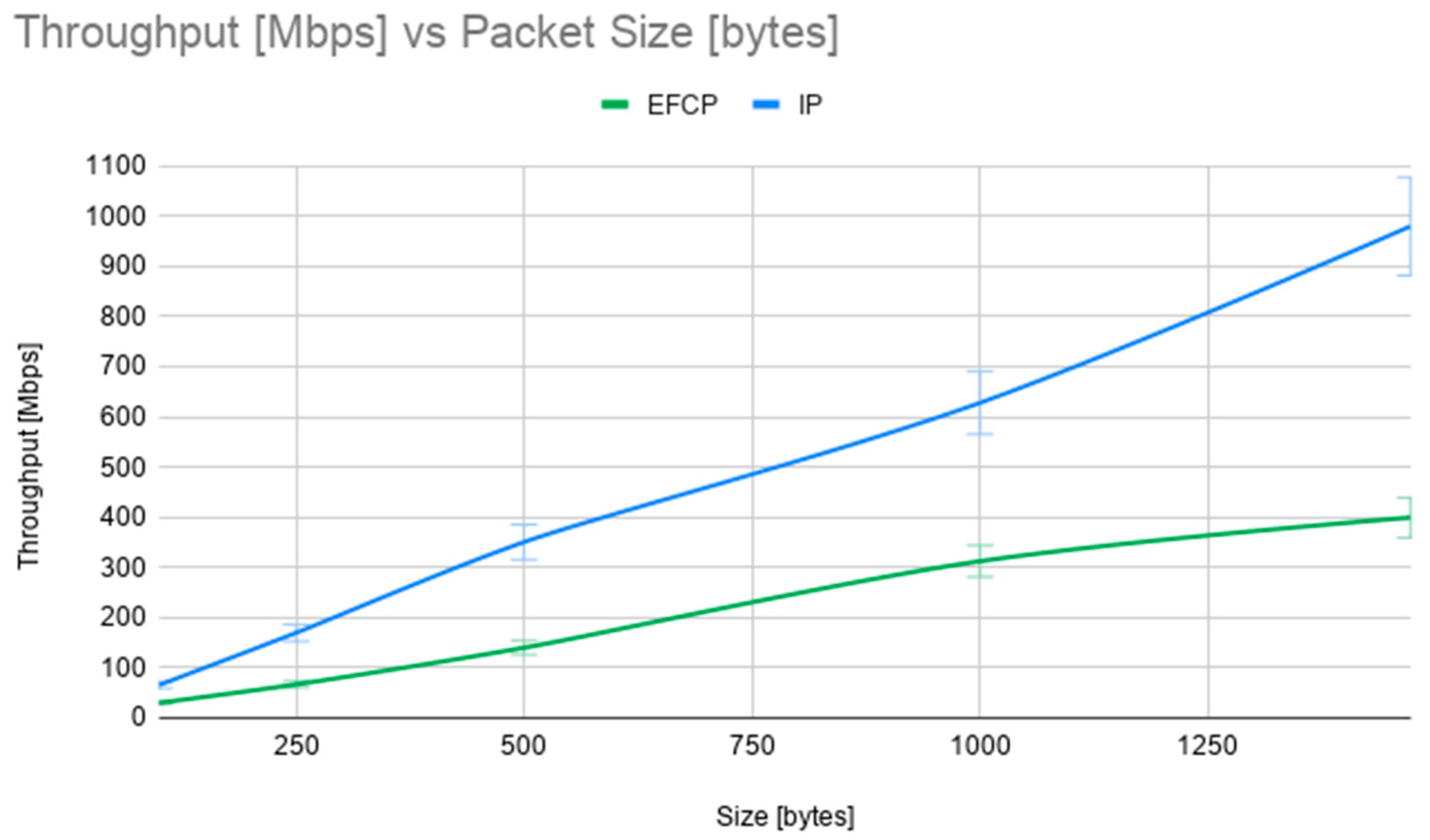
Figure 17 displays the throughput in Mbps measured by the custom C application in the AWS VM scenario. The higher amount of CPUs and RAM memory available in this setup allows BMv2 to reach much higher throughputs than in the local VM scenario: around 1 Gbps in the IP case and around 400 Mbps in the EFCP case. In this experimental setup the differences between the IP and the EFCP processing pipelines become more significant, highlighting the more complex (and time-consuming) packet processing pipeline implemented in the EFCP case, and showing the limitations of the BMv2 model (which again is not designed to play the role of a production-grade software switch). As explained in Section 6, we will carry out a larger set of experiments with the hardware-based EFCP pipeline implementation, which we expect to have the same performance as its IP counterpart.
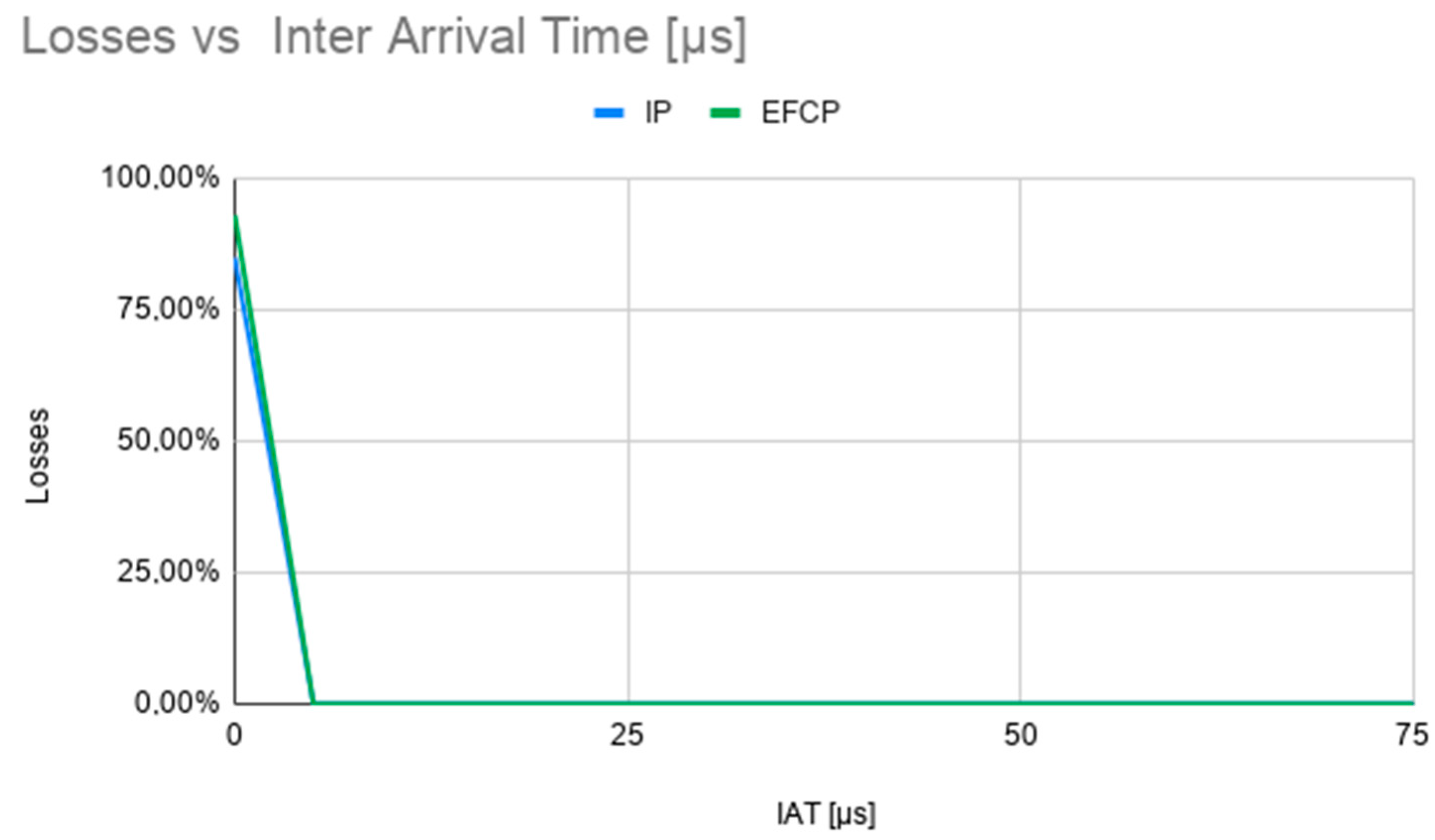
Packet loss, shown in Figure 18, is also lower in this configuration, dropping to 0 for packet inter-arrival times of more than 5 microseconds.
6. Next Steps: Complete RINA Interior Router Implementation
Having prototyped the RINA interior router’s data plane with the BMv2 model and its control plane with simple programs capable of interacting with the P4 Runtime API, the authors are now ready to proceed with the full implementation using real hardware. The target forwarding ASIC for the implementation is the Barefoot Network’s (now Intel’s) Tofino, as used by the EdgeCore Wedge100BF-32X (Edge-Core Networks, Taiwan) switch.
6.1. Data Plane
The P4 RINA interior router program developed for the BMv2 target presented in this paper will be adapted to the specifics of the Tofino mode, both to optimize and to introduce specific features, such as Tofino’s fixed-function APIs.
6.2. Control Plane
The IPC Management and Layer Management components of IRATI [1]—an open-source RINA implementation for Linux—will be integrated within the switch’s control plane software to provide intelligent and dynamic forwarding decisions, as shown in Figure 19.
The layer management components of IRATI can be thought as “control plane components” in user space that configure the “data plane” components implemented at the Linux kernel (where the IPCP Data-Transfer components execute). The control plane components are: (i) the IPC Manager, a daemon that oversees and configures the local instances of IPC Processes; and (ii) the layer management components of the IPC Processes; namely the IPCP Layer Management as well as the Distributed Fabric Daemon (DFD) and Shim DFD.
In IRATI the layer management components in the user space interact with the “data plane” components at the Linux kernel via two dedicated Linux character devices:
- dev/irati-ctrl. The “management” API to create and configure the “data-transfer” components of the IPCP (including forwarding tables).
- /dev/irati. The “I/O (Input/Output)” API to read and write packets addressed to or generated by the layer management components of the IPCP.
The manipulation of such character devices is handled by the librina library, which provides higher-level interfaces to other components of the IPC Manager Daemon and the IPCP Daemon. Hence, by adapting librina to use the P4 Runtime API (for layer management packet I/O, pipeline instantiation and forwarding table manipulation) instead of the Linux character devices, it will be possible to reuse all remaining IPCP Daemon and IPC Manager Daemon code base.
The DFD is a daemon that is part of the distributed network management application running in the DC. Instead of a centralized Network Management System, a set of DFD instances—one per physical server or network element—collaborate to carry out DC-wide resource discovery, allocation, and monitoring tasks. For instance, DFDs create new DIFs on behalf of customer requests, and allocate resources (memory, CPU, bandwidth) to them. To carry out these functions, the DFD has the following main components: (i) DFD Coordinator, which manages the discovery of peer DFDs and the connectivity to them; (ii) the Intent processor, which decomposes user requests into a set of DC resources that need to be booked; (iii) the Composition Computation Engine (CCE), which computes and reserves the set of resources required to fulfil a user request in a decentralized way; and (iv) the Device Abstraction Layer (DAL), which allows the DFD to interact with the local managed resource. In the case of a RINA interior router, the DFD DAL interacts with the IRATI layer management daemons.
6.3. Security
Data plane security components to carry out encryption of PDUs are out of the scope of the initial implementation—since they require target-specific hardware support functions—but may be considered to be future enhancements. In any case, RINA facilitates the efficiency of the implementation and reusability of such components due to the fact that RINA security policies—e.g., encryption algorithms—are applied to DIFs, not to specific protocols, hence different IPCPs may reuse the same encryption module [24].
7. Conclusions
This work has proven the feasibility of implementing a RINA interior router (or target) with the P4 programming language as well as a custom control plane to communicate the target with the upper layers. To that end, we have evaluated and integrated different open-source tools. After initial validation with the BMv2 software target, we conclude that P4 provides enough features to implement a RINA interior router.
The authors are currently developing a full RINA control plane that allows the IRATI RINA implementation [1] to communicate with the P4-enabled target via the P4Runtime API exposed by the Stratum Network OS. The authors also plan to design and prototype a RINA border router, to verify the impact of the P4 language limitations explained in Section 2 of this paper. We anticipate that, at least, the language must support generating new packets, as well as better capabilities for inter-packet state management to facilitate the implementation of flow and retransmission control policies.
Hence, next steps are to test the data plane on real white box hardware that incorporates a P4-enabled ASIC such as Barefoot Tofino, and finalize the integration between the silicon target, the control plane and the IRATI RINA implementation.
Author Contributions
Conceptualization, E.G.; data curation, S.G.; formal analysis, E.G. and S.B.; investigation, S.G., C.F.; methodology, C.F., E.G.; software, S.G., C.F.; experiments, C.F., S.G.; supervision, S.B.; writing–original draft, C.F., S.G. and E.G.; writing–review & editing, E.G., C.F., and S.B. All authors have read and agreed to the published version of the manuscript.
Funding
This research was supported by the Spanish Center for the Development of Industrial Technology (CDTI) and the Ministry of Economy, Industry and Competitiveness under grant/project CER-20191015/Open, Virtualized Technology Demonstrators for Smart Networks (Open-VERSO). This work was also supported by the State Program for the Promotion of Excellent Scientific and Technical Research, Subprogram for Knowledge Generation (TEC2017-84423-C3-1-P).
Acknowledgments
The authors would like to thank Antonin Bas (VMWare) and Andy Fingerhut (Cisco Systems) for their great support in resolving questions and doubts on the BMv2 model usage and performance evaluation, as well as Sergio Slobodrian, Mahdi Hirab and Kaniz Mahdi from Ciena for the discussions on how to best use RINA for the distributed datacenter environment provided by the ENCQOR (Evolution of Networked Services through a Corridor in Québec and Ontario for Research and Innovation) Distributed Fabric (EDF).
Conflicts of Interest
The authors declare no conflict of interest.
Abbreviations
| ACL | Access Control List |
| API | Application Programming Interface |
| ASIC | Application Specific Integrated Circuit |
| AWS | Amazon Web Services |
| BQE | Buffering Queuing Engine |
| BMv2 | Behavioral Model Version 2 |
| BSP | Board Support Package |
| CCE | Composition Computation Engine |
| CLI | Command Line Interface |
| CPU | Central Processing Unit |
| DAL | Device Abstraction Layer |
| DFD | Distributed Fabric Daemon |
| DIF | Distributed IPC Facility |
| DC | Data Center |
| DPDK | Data Plane Development Kit |
| ECN | Explicit Congestion Notification |
| EFCP | Error and Flow-Control Protocol |
| ENCQOR | Evolution of Networked Services Through a Corridor in Quebec and Ontario for Research and Innovation |
| FIFO | First in First Out |
| FPGA | Field Programmable Gate Array |
| gRPC | Google Remote Procedure Calls |
| gNMI | gRPC Network Management Interface |
| gNOI | gRPC Network Operations Interface |
| IP | Internet Protocol |
| IPCP | IPC Process |
| I/O | Input Output |
| IRATI | Investigating RINA as an Alternative to TCP/IP |
| JSON | Java Script Object Notation |
| MA | Management Agent |
| MPLS | Multi-Protocol Label Switching |
| NIC | Network Interface Card |
| NOS | Network Operating System |
| ONIE | Open Network Install Environment |
| ONL | Open Network Linux |
| ONF | Open Networking Foundation |
| OS | Operating System |
| PDU | Protocol Data Unit |
| PHAL | Physical Hardware Access Layer |
| PoC | Proof of Concept |
| RINA | Recursive InterNetwork Architecture |
| RPC | Remote Procedure Call |
| SDDC | Software-Defined Data Center |
| SDE | Software Development Environment |
| ToR | Top of Rack |
| VLAN | Virtual Local Area Network |
| VxLAN | Virtual Extensible LAN |
| VM | Virtual Machine |
References
- Grasa, E.; Tarzan, M.; Bergesio, L.; Gastón, B.; Maffione, V.; Salvestrini, F.; Vrijders, S.; Staessens, D. IRATI: Open source RINA implementation for Linux. Softw. Impacts 2019, 1. [Google Scholar] [CrossRef]
- Maffione, V. A Light Rina Implementation. Available online: https://github.com/rlite/rlite (accessed on 7 July 2020).
- Wang, Y.; Matta, I.; Esposito, F.; Day, J. Introducing protorina: A prototype for programming recursive-networking policies. ACM SIGCOMM Comput. Commun. Rev. 2014, 44, 129–131. [Google Scholar] [CrossRef]
- Vessely, V.; Marek, M.; Hykel, T.; Rysavy, O. Rinasim: Your recursive internetwork architecture simulator. In Proceedings of the OMNeT++ Community Summit, Zurich, Switzerland, 3–4 September 2015. [Google Scholar]
- Rizzo, L. Netmap: A novel framework for fast packet i/o. In Proceedings of the 2012 USENIX Annual Technical Conference, Boston, MA, USA, 13–15 June 2012. [Google Scholar]
- Kourtis, M.-A.; Xilouris, G.; Riccobene, V.; McGrath, M.J.; Petralia, G.; Koumaras, H.; Gardikis, G.; Liberal, F. Enhancing vnf performance by exploiting sr-iov and dpdk packet processing acceleration. In Proceedings of the 2015 IEEE Conference on Network Function Virtualisation and Software Defined Network (NFV-SDN), San Francisco, CA, USA, 18–21 November 2015. [Google Scholar]
- Gallenmuller, S.; Emmerich, P.; Wohlfart, F.; Raumer, D.; Carle, G. Comparison of framework for high-performance packet IO. In Proceedings of the 2015 ACM/IEEE Symposium on Architectures for Networking and Communications Systems (ANCS), Oakland, CA, USA, 7–8 May 2015. [Google Scholar]
- Zilberman, N.; Audzevich, Y.; Kalogeridou, G.; Manihatty-Bojan, N.; Zhang, J.; Moore, A. Netfpga: Rapid prototyping of networking devices in open source. In Proceedings of the 2015 ACM Conference on Special Interest Group on Data Communication, London, UK, 17–21 August 2015; pp. 363–364. [Google Scholar]
- Bosshart, P.; Daly, D.; Gibb, G.; Izzard, M.; McKeown, N.; Rexford, J.; Schlesinger, C.; Talayco, D.; Vahdat, A.; Varghese, G.; et al. P4: Programming protocol-independent packet processors. SIGCOMM Comput. Commun. Rev. 2014, 44, 87–95. [Google Scholar] [CrossRef]
- Dai, B.; Xu, G.; Huang, B.; Qin, P.; Xu, Y. Enabling network innovation in data center networks with software defined networking: A survey. J. Netw. Comput. Appl. 2017, 94, 33–49. [Google Scholar] [CrossRef]
- Lopez, D. Deliverable D2.1: Use Cases Description and Requirements Analysis Report; PRISTINE Project Research Report: Madrid, Spain, 2014. [Google Scholar]
- León, S.; Perelló, J.; Careglio, D.; Grasa, E.; Lopez, D.; Aranda, P. Scalable topological forwarding and routing policies in RINA-enabled programmable datacenters. Trans. Emerg. Telecommun. Technol. 2017, 28. [Google Scholar] [CrossRef] [Green Version]
- Teymoori, P.; Hayes, D.; Welzl, M.; Gjessing, S. Even lower latency, even better fairness: Logistic growth congestion control in datacenters. In Proceedings of the IEEE Conference on Local Computer Networks (LCN), Dubai, United Arab Emirates, 7–10 November 2016. [Google Scholar]
- Leon, S.; Perelló, J.; Careglio, D.; Grasa, E.; Tarzan, M.; Davies, N.; Thompson, P. Assuring QoS guarantees for Heterogeneous Services in RINA networks with deltaQ. In Proceedings of the 6th Workshop of Network Infrastructure Services as Part of Cloud Computing, Luxembourg, 12 December 2016. [Google Scholar]
- Maffione, V.; Salvestrini, F.; Grasa, E.; Bergesio, L.; Tarzan, M. A software development kit to exploit rina programmability. In Proceedings of the IEEE International Conference on Communications, Kuala Lumpur, Malaysia, 23–27 May 2016. [Google Scholar]
- P4 Language Consortium; P416 Language Specification, Version 1.0.0, May 2017. Available online: https://p4.org/p4-spec/docs/P4-16-v1.0.0-spec.html (accessed on 7 July 2020).
- Sivaraman, A.; McKeown, N.; Subramanian, S.; Alizadeh, M.; Chole, S.; Chuang, S.-T.; Agrawal, A.; Balakrishnan, H.; Edsall, T.; Katti, S. Programmable packet scheduling at line rate. In Proceedings of the 2016 ACM SIGCOMM Conference, Florianopolis, Brazil, 22–26 August 2016; pp. 44–57. [Google Scholar]
- Dang, H.T.; Wang, H.; Jepsen, T.; Brebner, G.; Kim, C.; Rexford, J.; Soule, R.; Weatherspoon, H. Whippersnapper; A P4 language benchmark suite. In Proceedings of the Symposium on SDN Research (SOSR), Santa Clara, CA, USA, 3–4 April 2017; pp. 95–101. [Google Scholar] [CrossRef]
- Bianchi, G.; Welzl, M.; Tulumello, A.; Belocchi, G.; Faltelli, M.; Pontarelli, S. A fully portable tcp implementation using xfsms. In Proceedings of the ACM SIGCOMM 2018 Conference on Posters and Demos, Budapest, Hungary, 20–25 August 2018; pp. 99–101. [Google Scholar]
- P4 Behavioral Model Repository. Available online: https://github.com/p4lang/behavioral-model (accessed on 7 July 2020).
- P4 API Working Group; P4 Runtime Specification Version 1, October 2019. Available online: https://p4.org/p4runtime/spec/v1.0.0/P4Runtime-Spec.html (accessed on 7 July 2020).
- Open Networking Foundation. Stratum Project Website. Available online: https://www.opennetworking.org/stratum/ (accessed on 7 July 2020).
- P4 Community; A shell for P4 Runtime. Available online: https://github.com/p4lang/p4runtime-shell (accessed on 7 July 2020).
- Grasa, E.; Rysavy, O.; Lichtner, O.; Asgari, H.; Day, J.; Chitkushev, L. From protecting protocols to protecting layers: Designing, implementing and experimenting with security policies in RINA. In Proceedings of the IEEE ICC, Kuala Lumpur, Malaysia, 23–27 May 2016. [Google Scholar]
Figure 1.
Summary of the development workflow of a P4 program (source ONF, Open Networking Foundation).
Figure 1.
Summary of the development workflow of a P4 program (source ONF, Open Networking Foundation).

Figure 2.
Example of the systems in datacenters (DC) and their connectivity.

Figure 3.
Example design for the DIFs in a DC, showing VM (Virtual Machine) to VM connectivity. Small circles represent IPC Processes (IPCPs), while large circles represent application instances [15].
Figure 3.
Example design for the DIFs in a DC, showing VM (Virtual Machine) to VM connectivity. Small circles represent IPC Processes (IPCPs), while large circles represent application instances [15].

Figure 4.
Example design for the DIFs in multiple DCs, showing VM (Virtual Machine) to VM connectivity. Small circles represent IPC Processes (IPCPs), while large circles represent application instances.
Figure 4.
Example design for the DIFs in multiple DCs, showing VM (Virtual Machine) to VM connectivity. Small circles represent IPC Processes (IPCPs), while large circles represent application instances.

Figure 5.
RINA router use cases.

Figure 6.
Functional split for the components of a RINA router implementation using P4.

Figure 7.
Design of a RINA over Ethernet interior router pipeline, using the v1model architecture.

Figure 8.
Data plane ingress processing logic.

Figure 9.
P4 Runtime API Client setting up session with server.

Figure 10.
P4 Runtime API Client setting up session with server.

Figure 11.
Stratum implementation running on top of BMv2 (source: ONF, Open Networking Foundation).

Figure 12.
Python code for P4Runtime-Shell session setup and packet monitoring.

Figure 13.
Virtual environment with 2 hosts and 1 Stratum BMv2 software switch.

Figure 14.
Configuration of the forwarding table entries using the P4 Runtime API from a Python program.
Figure 14.
Configuration of the forwarding table entries using the P4 Runtime API from a Python program.

Figure 15.
Local VM scenario. Throughput in Mbps vs. packet size in bytes.

Figure 16.
Local VM scenario. Packet loss vs. inter-arrival time (IAT) for a packet size of 500 bytes.
Figure 16.
Local VM scenario. Packet loss vs. inter-arrival time (IAT) for a packet size of 500 bytes.

Figure 17.
AWS VM scenario. Throughput in Mbps vs. packet size in bytes.

Figure 18.
AWS VM scenario. Packet loss vs. inter-arrival time (IAT) for a packet size of 500 bytes.
Figure 18.
AWS VM scenario. Packet loss vs. inter-arrival time (IAT) for a packet size of 500 bytes.

Figure 19.
Adapting IRATI layer management modules to implement the router’s control plane.

© 2020 by the authors. Licensee MDPI, Basel, Switzerland. This article is an open access article distributed under the terms and conditions of the Creative Commons Attribution (CC BY) license (http://creativecommons.org/licenses/by/4.0/).
Share and Cite
MDPI and ACS Style
Fernández, C.; Giménez, S.; Grasa, E.; Bunch, S. A P4-Enabled RINA Interior Router for Software-Defined Data Centers. Computers 2020, 9, 70. https://0-doi-org.brum.beds.ac.uk/10.3390/computers9030070
AMA Style
Fernández C, Giménez S, Grasa E, Bunch S. A P4-Enabled RINA Interior Router for Software-Defined Data Centers. Computers. 2020; 9(3):70. https://0-doi-org.brum.beds.ac.uk/10.3390/computers9030070
Chicago/Turabian StyleFernández, Carolina, Sergio Giménez, Eduard Grasa, and Steve Bunch. 2020. "A P4-Enabled RINA Interior Router for Software-Defined Data Centers" Computers 9, no. 3: 70. https://0-doi-org.brum.beds.ac.uk/10.3390/computers9030070
Note that from the first issue of 2016, this journal uses article numbers instead of page numbers. See further details here.