Management of γ-Alumina with High-Efficient {111} External Surfaces for HDS Reactions

 , and
, and
Abstract
:
1. Introduction
2. Results and Discussion
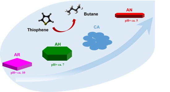
2.1. Preparation of the Alumina with Varied {111} Facet Ratios
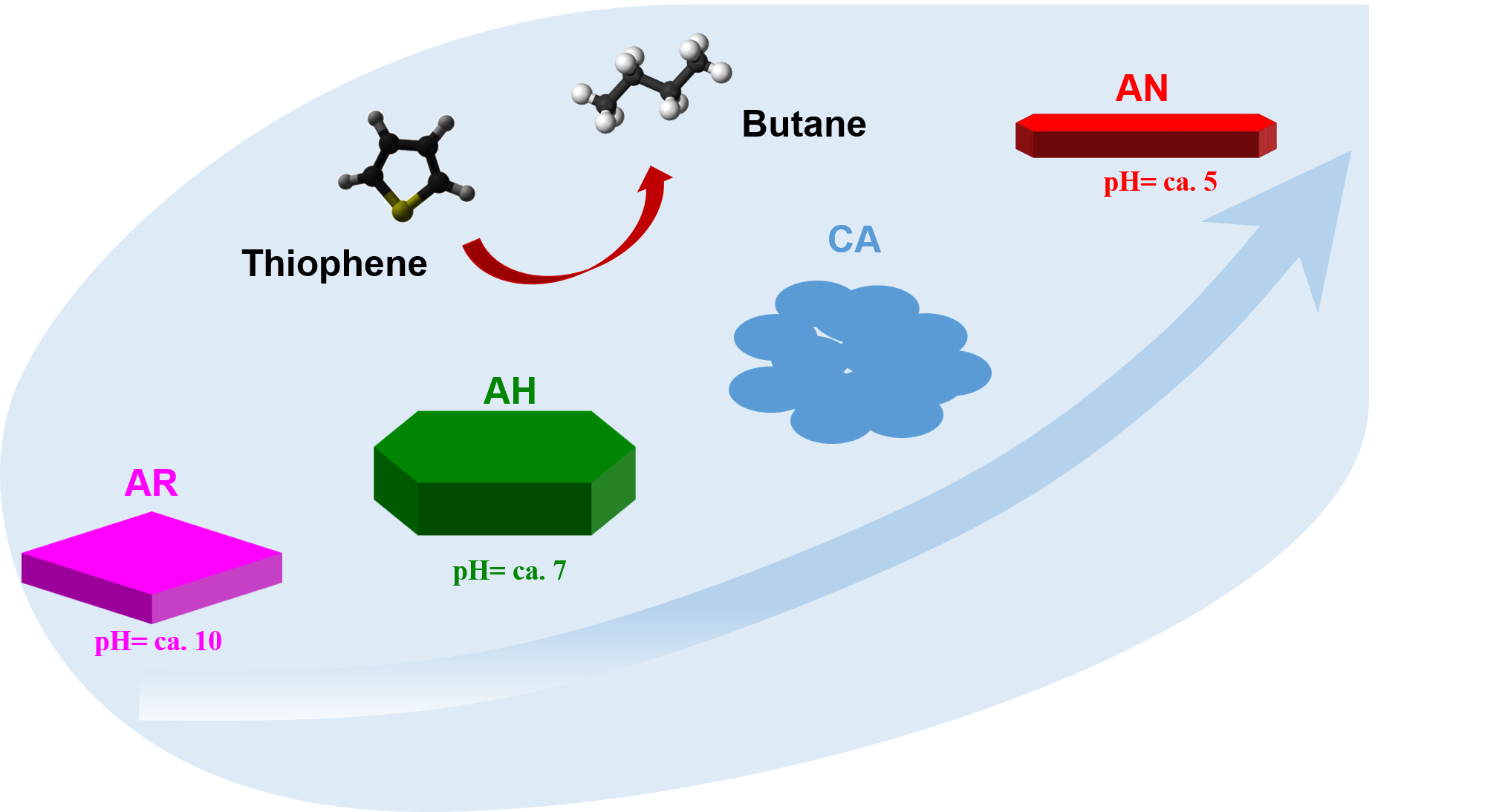
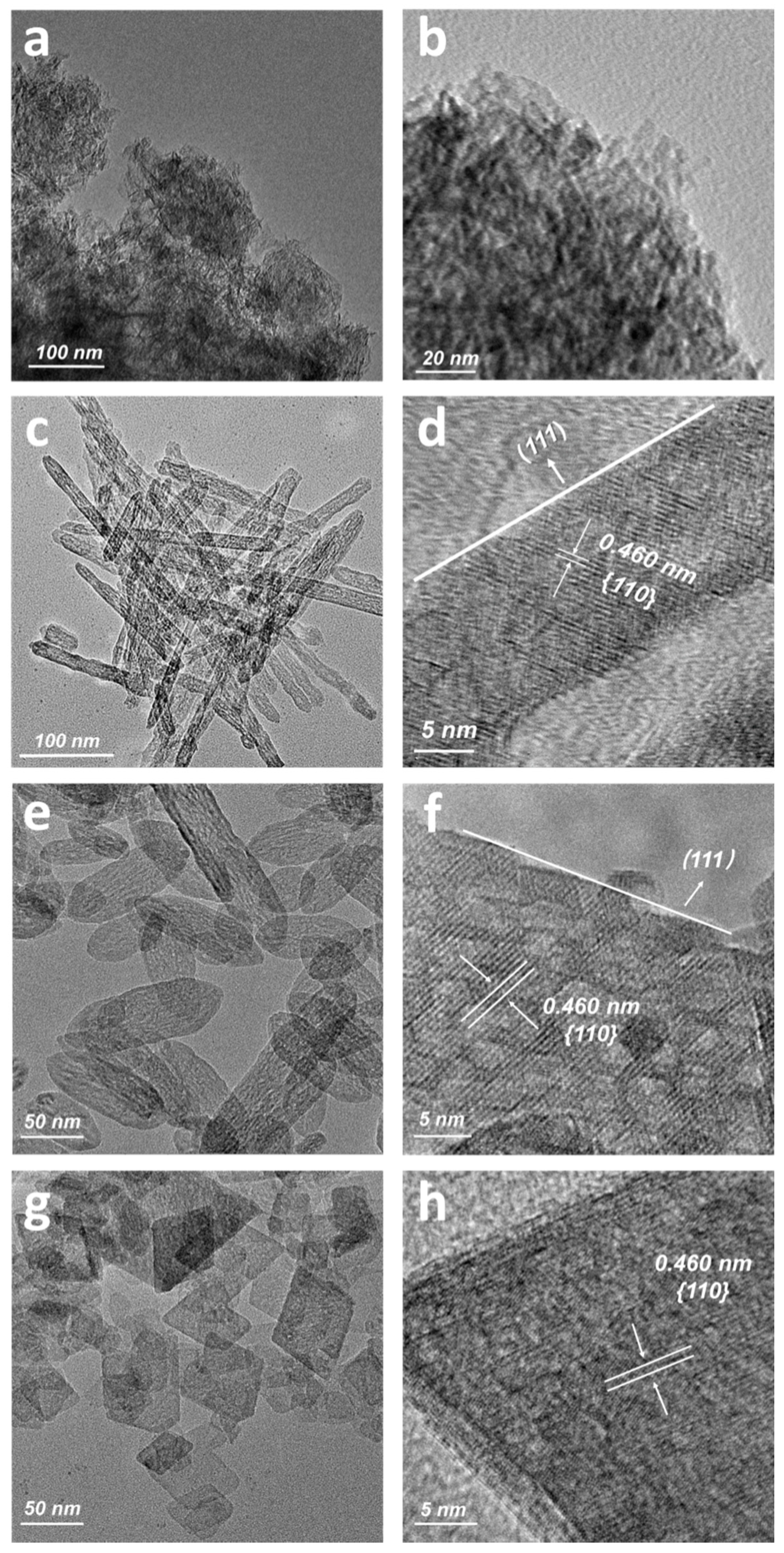
2.2. Physiochemical Properties
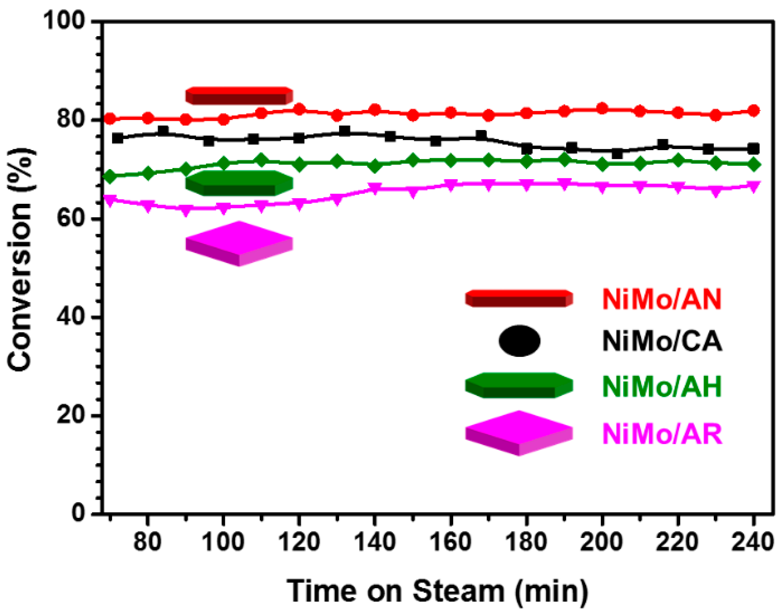
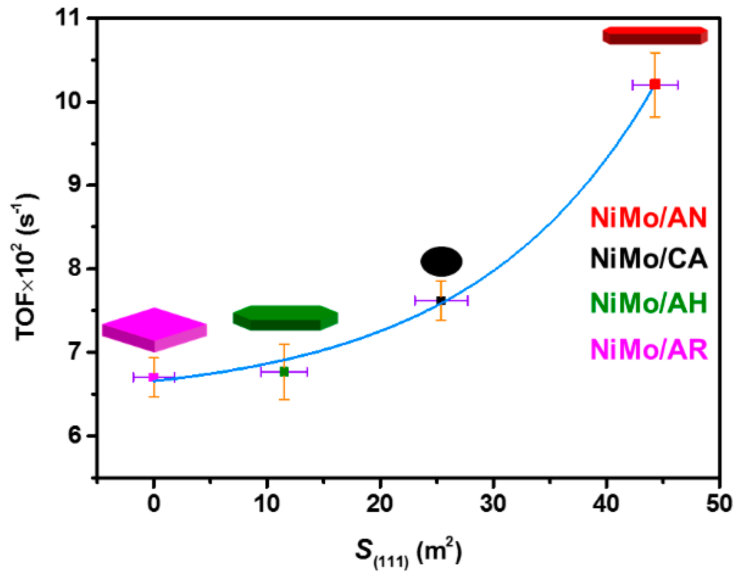
2.3. HDS Performance of Thiophene and Dibenzothiophene over NiMo/Al2O3 Catalysts
3. Experimental Sections
3.1. Materials
3.2. Preparation of γ-Alumina Support
3.3. Preparation of HDS Catalysts
3.4. Characterization
3.5. Catalytic Performance Evaluation
3.6. Calculation of the Facet Ratio by TEM Measurements
3.7. Calculation of the Slab Length (LMoS2) and Stacking Numbers (NMoS2) of MoS2 Nanoslabes by TEM Measurements
4. Conclusions
Supplementary Materials
Author Contributions
Funding
Acknowledgments
Conflicts of Interest
References
- dos Santos, A.S.; Girard, E.; Leflaive, P.; Brunet, S. Competitive adsorptions between thiophenic compounds over a CoMoS/Al2O3 catalyst under deep HDS of FCC gasoline. Appl. Catal. A: Gen. 2019, 570, 292–298. [Google Scholar] [CrossRef]
- Zhang, H.; Lin, H.; Zheng, Y. Application of Uniform Design Method in the Optimization of Hydrothermal Synthesis for Nano MoS2 Catalyst with High HDS Activity. Catalysts 2018, 8, 654. [Google Scholar] [CrossRef] [Green Version]
- Neto, A.V.d.; Leite, E.R.; da Silva, V.T.; Zotin, J.L.; Urquieta-González, E.A. NiMoS HDS catalysts – The effect of the Ti and Zr incorporation into the silica support and of the catalyst preparation methodology on the orientation and activity of the formed MoS2 slabs. Appl. Catal. A Gen. 2016, 528, 74–85. [Google Scholar] [CrossRef]
- Okamoto, Y.; Breysse, M.; Dhar, G.M.; Song, C. Effect of support in hydrotreating catalysis for ultra clean fuels. Catal. Today 2003, 86, 1–3. [Google Scholar] [CrossRef]
- Puello-Polo, E.; Pájaro, Y.; Márquez, E. Effect of the Gallium and Vanadium on the Dibenzothiophene Hydrodesulfurization and Naphthalene Hydrogenation Activities Using Sulfided NiMo-V2O5/Al2O3-Ga2O3. Catalysts 2020, 10, 894. [Google Scholar] [CrossRef]
- Li, F.; Liang, J.; Zhu, W.; Song, H.; Wang, K.; Li, C. High Active Zn/Mg-Modified Ni–P/Al2O3 Catalysts Derived from ZnMgNiAl Layered Double Hydroxides for Hydrodesulfurization of Dibenzothiophene. Catalysts 2017, 7, 202. [Google Scholar] [CrossRef]
- Abdelkader, A.; Osman, A.I.; Halawy, S.A.; Mohamed, M.A. Preparation and characterization of mesoporous γ-Al2O3 recovered from aluminum cans waste and its use in the dehydration of methanol to dimethyl ether. J. Mater. Cycles Waste Manage. 2018, 20, 1428–1436. [Google Scholar] [CrossRef]
- Osman, A.I.; Abu-Dahrieh, J.K.; McLaren, M.; Laffir, F.; Rooney, D.W. Characterisation of Robust Combustion Catalyst from Aluminium Foil Waste. ChemistrySelect 2018, 3, 1545–1550. [Google Scholar] [CrossRef] [Green Version]
- Bara, C.; Devers, E.; Digne, M.; Lamic-Humblot, A.-F.; Pirngruber, G.D.; Carrier, X. Surface Science Approaches for the Preparation of Alumina-Supported Hydrotreating Catalysts. ChemCatChem 2015, 7, 3422–3440. [Google Scholar] [CrossRef]
- Bara, C.; Plais, L.; Larmier, K.; Devers, E.; Digne, M.; Lamic-Humblot, A.F.; Pirngruber, G.D.; Carrier, X. Aqueous-Phase Preparation of Model HDS Catalysts on Planar Alumina Substrates: Support Effect on Mo Adsorption and Sulfidation. J. Am. Chem. Soc. 2015, 137, 15915–15928. [Google Scholar] [CrossRef] [Green Version]
- Arrouvel, C.; Breysse, M.; Toulhoat, H.; Raybaud, P. Effects of PH2O, PH2S, PH2 on the surface properties of anatase–TiO2 and γ-Al2O3: A DFT study. J. Catal. 2005, 232, 161–178. [Google Scholar] [CrossRef]
- Costa, D.; Arrouvel, C.; Breysse, M.; Toulhoat, H.; Raybaud, P. Edge wetting effects of γ-Al2O3 and anatase-TiO2 supports by MoS2 and CoMoS active phases: A DFT study. J. Catal. 2007, 246, 325–343. [Google Scholar] [CrossRef]
- Sakashita, Y.; Araki, Y.; Honna, K.; Shimada, H. Orientation and morphology of molybdenum sulfide catalysts supported on titania particles, observed by using high-resolution electron microscopy. Appl. J. Catal. A Gen. 2000, 197, 247–253. [Google Scholar] [CrossRef]
- Kibsgaard, J.; Clausen, B.S.; Topsøe, H.; Lægsgaard, E.; Lauritsen, J.V.; Besenbacher, F. Scanning tunneling microscopy studies of TiO2-supported hydrotreating catalysts: Anisotropic particle shapes by edge-specific MoS2–support bonding. J. Catal. 2009, 263, 98–103. [Google Scholar] [CrossRef]
- Liu, Y.; Wang, H.; Liu, Y.; Zhao, J.; Liu, C. Reactive Adsorption Desulfurization on Cu/ZnO Adsorbent: Effect of ZnO Polarity Ratio on Selective Hydrogenation. Energ. Fuel 2017, 31, 9930–9938. [Google Scholar] [CrossRef]
- Sitamraju, S.; Xiao, J.; Janik, M.J.; Song, C. Active Sites on Ti–Ce Mixed Metal Oxides for Reactive Adsorption of Thiophene and Its Derivatives: A DFT Study. J. Phys. Chem. C 2015, 119, 5903–5913. [Google Scholar] [CrossRef]
- Wang, X.; Ding, L.; Zhao, Z.; Xu, W.; Meng, B.; Qiu, J. Novel hydrodesulfurization nano-catalysts derived from Co3O4 nanocrystals with different shapes. Catal. Today 2011, 175, 509–514. [Google Scholar] [CrossRef]
- Laurenti, D.; Phung-Ngoc, B.; Roukoss, C.; Devers, E.; Marchand, K.; Massin, L.; Lemaitre, L.; Legens, C.; Quoineaud, A.-A.; Vrinat, M. Intrinsic potential of alumina-supported CoMo catalysts in HDS: Comparison between γc, γT, and δ-alumina. J. Catal. 2013, 297, 165–175. [Google Scholar] [CrossRef]
- Stockmann, R.M.; Zandbergen, H.W.; van Langeveld, A.D.; Moulijn, J.A. Investigation of MoS2 on γ-Al2O3 by HREM with atomic resolution. J. Mol. Catal. A Chem. 1995, 102, 147–161. [Google Scholar] [CrossRef]
- Digne, M.; Sautet, P.; Raybaud, P.; Euzen, P.; Toulhoat, H. Use of DFT to achieve a rational understanding of acid-basic properties of γ-alumina surfaces. J. Catal. 2004, 226, 54–68. [Google Scholar] [CrossRef]
- Wang, Y.; Yang, J.; Gu, R.; Peng, L.; Guo, X.; Xue, N.; Zhu, Y.; Ding, W. Crystal-Facet Effect of γ-Al2O3 on Supporting CrOx for Catalytic Semihydrogenation of Acetylene. ACS Catal. 2018, 8, 6419–6425. [Google Scholar] [CrossRef]
- Hayden, T.F.; Dumesic, J.A. Studies of the structure of molybdenum oxide and sulfide supported on thin films of alumina. J. Catal. 1987, 103, 366–384. [Google Scholar] [CrossRef]
- Sakashita, Y. Effects of surface orientation and crystallinity of alumina supports on the microstructures of molybdenum oxides and sulfides. Surf. Sci. 2001, 489, 45–48. [Google Scholar] [CrossRef]
- Sakashita, Y.; Yoneda, T. Orientation of MoS2 Clusters Supported on Two Kinds of γ-Al2O3 Single Crystal Surfaces with Different Indices. J. Catal. 1999, 185, 487–495. [Google Scholar] [CrossRef]
- Bara, C.; Lamic-Humblot, A.-F.; Fonda, E.; Gay, A.-S.; Taleb, A.-L.; Devers, E.; Digne, M.; Pirngruber, G.D.; Carrier, X. Surface-dependent sulfidation and orientation of MoS2 slabs on alumina-supported model HDS catalysts. J. Catal. 2016, 344, 591–605. [Google Scholar] [CrossRef] [Green Version]
- Wang, L.; Liu, H.; Fan, Y.; Yuan, P.; Huang, D.; Oyama, S.T.; Wang, T.; Bao, X. Cooperative bimetallic catalyst for thio-etherification reaction prepared by crystal-facet engineering of γ-Al2O3 support. Catal. Today 2020. [Google Scholar] [CrossRef]
- Krokidis, X.; Raybaud, P.; Gobichon, A.-E.; Rebours, B.; Euzen, P.; Toulhoat, H. Theoretical Study of the Dehydration Process of Boehmite to γ-Alumina. J. Phys. Chem. B 2001, 105, 5121–5130. [Google Scholar] [CrossRef]
- Cai, W.; Zhang, S.; Lv, J.; Chen, J.; Yang, J.; Wang, Y.; Guo, X.; Peng, L.; Ding, W.; Chen, Y.; et al. Nanotubular Gamma Alumina with High-Energy External Surfaces: Synthesis and High Performance for Catalysis. ACS Catal. 2017, 7, 4083–4092. [Google Scholar] [CrossRef]
- Lee, J.; Jang, E.J.; Jeong, H.Y.; Kwak, J.H. Critical role of (100) facets on γ-Al2O3 for ethanol dehydration: Combined efforts of morphology-controlled synthesis and TEM study. Appl. Catal. A Gen. 2018, 556, 121–128. [Google Scholar] [CrossRef]
- Kovarik, L.; Genc, A.; Wang, C.; Qiu, A.; Peden, C.H.F.; Szanyi, J.; Kwak, J.H. Tomography and High-Resolution Electron Microscopy Study of Surfaces and Porosity in a Plate-like γ-Al2O3. J. Phys. Chem. C 2013, 117, 179–186. [Google Scholar] [CrossRef]
- Dong, Y.; Xu, Y.; Zhang, Y.; Lian, X.; Yi, X.; Zhou, Y.; Fang, W. Synthesis of hierarchically structured alumina support with adjustable nanocrystalline aggregation towards efficient hydrodesulfurization. Appl. Catal. A Gen. 2018, 559, 30–39. [Google Scholar] [CrossRef]
- Lai, W.; Song, W.; Pang, L.; Wu, Z.; Zheng, N.; Li, J.; Zheng, J.; Yi, X.; Fang, W. The effect of starch addition on combustion synthesis of NiMo–Al2O3 catalysts for hydrodesulfurization. J. Catal. 2013, 303, 80–91. [Google Scholar] [CrossRef]
- Ali, S.A.; Ahmed, S.; Ahmed, K.W.; Al-Saleh, M.A. Simultaneous hydrodesulfurization of dibenzothiophene and substituted dibenzothiophenes over phosphorus modified CoMo/Al2O3 catalysts. Fuel Process. Technol. 2012, 98, 39–44. [Google Scholar] [CrossRef]
- Lai, W.; Xu, Y.; Ren, Y.; Yang, L.; Zheng, J.; Yi, X.; Fang, W. Insight into the effect of non-stoichiometric sulfur on a NiMoS hydrodesulfurization catalyst. Catal. Sci. Technol. 2016, 6, 497–506. [Google Scholar]
- Zhang, Z.; Pinnavaia, T.J. Mesostructured γ-Al2O3 with a lathlike framework morphology. J. Am. Chem. Soc. 2002, 124, 12294–12301. [Google Scholar] [CrossRef]
- Fan, Y.; Xiao, H.; Shi, G.; Liu, H.; Qian, Y.; Wang, T.; Gong, G.; Bao, X. Citric acid-assisted hydrothermal method for preparing NiW/USY–Al2O3 ultradeep hydrodesulfurization. J. Catal. 2011, 279, 27–35. [Google Scholar] [CrossRef]
- Zhang, X.; Cui, W.W.; Page, K.L.; Pearce, C.I.; Bowden, M.E.; Graham, T.R.; Shen, Z.Z.; Li, P.; Wang, Z.M.; Kerisit, S.; et al. Size and Morphology Controlled Synthesis of Boehmite Nanoplates and Crystal Growth Mechanisms. Cryst. Growth Des. 2018, 18, 3596–3606. [Google Scholar] [CrossRef]
- Wang, X.; Chaka, A.; Scheffler, M. Effect of the Environment on α-Al2O3 (0001) Surface Structures. Phys. Rev. Lett. 2000, 84, 3650–3653. [Google Scholar] [CrossRef] [Green Version]
- Lai, W.; Pang, L.; Zheng, J.; Li, J.; Wu, Z.; Yi, X.; Fang, W.; Jia, L. The effect of starch addition on combustion synthesis of NiMo–Al2O3 catalysts for hydrodesulfurization. Fuel Process. Technol. 2013, 110, 8–16. [Google Scholar] [CrossRef]
- Mozhaev, A.V.; Nikulshin, P.A.; Pimerzin, A.A.; Maslakov, K.I.; Pimerzin, A.A. Investigation of co-promotion effect in NiCoMoS/Al2O3 catalysts based on Co2Mo10-heteropolyacid and nickel citrate. Catal. Today 2016, 271, 80–90. [Google Scholar] [CrossRef]


| Samples | Targeted pH | pa | Surface Area (m2 g−1) | Pore Volume (cm3 g−1) | Pore Size (nm) | S(111)d |
|---|---|---|---|---|---|---|
| AN | 5 | 0.4 b | 110.7 | 0.42 | 15.0 | 44.3 |
| CA | 11 | 0.1 c | 254.8 | 0.68 | 7.5 | 25.4 |
| AH | 10 | 0.1 b | 115.4 | 0.33 | 11.9 | 11.5 |
| AR | 13 | 0 b | 147.4 | 0.55 | 13.5 | 0 |
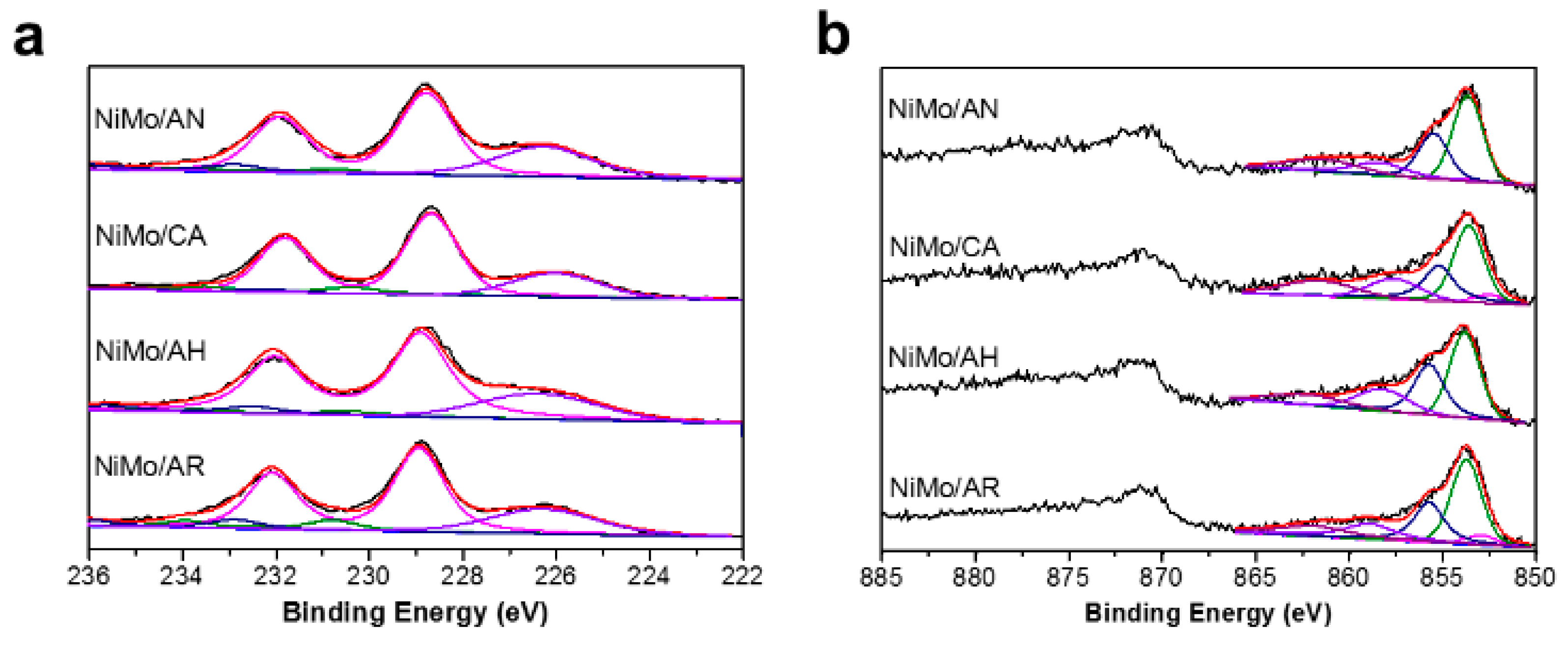
| Catalysts | Mo(IV) | Mo(V) | Mo(VI) | |||
|---|---|---|---|---|---|---|
| BE(eV) | %/atm. | BE(eV) | %/atm. | BE(eV) | %/atm. | |
| NiMo/AN | 228.8 | 88.3 | 230.5 | 4.9 | 232.4 | 7.9 |
| NiMo/CA | 228.7 | 87.2 | 230.5 | 8.4 | 232.5 | 4.4 |
| NiMo/AH | 228.8 | 85.0 | 230.6 | 5.9 | 232.5 | 9.1 |
| NiMo/AR | 228.8 | 80.8 | 230.6 | 10.0 | 232.5 | 9.2 |
| Catalysts | NiMoS Phase | NiSx Phase | NiOx Phase | |||
|---|---|---|---|---|---|---|
| BE(eV) | %/atm. | BE(eV) | %/atm. | BE(eV) | %/atm. | |
| NiMo/AN | 853.7 | 61.4 | 853.0 | 1.3 | 855.9 | 37.3 |
| NiMo/CA | 853.7 | 58.4 | 853.0 | 5.9 | 856.0 | 35.7 |
| NiMo/AH | 853.6 | 58.0 | 853.0 | 7.7 | 855.9 | 34.3 |
| NiMo/AR | 853.6 | 57.1 | 853.0 | 1.2 | 856.0 | 41.7 |
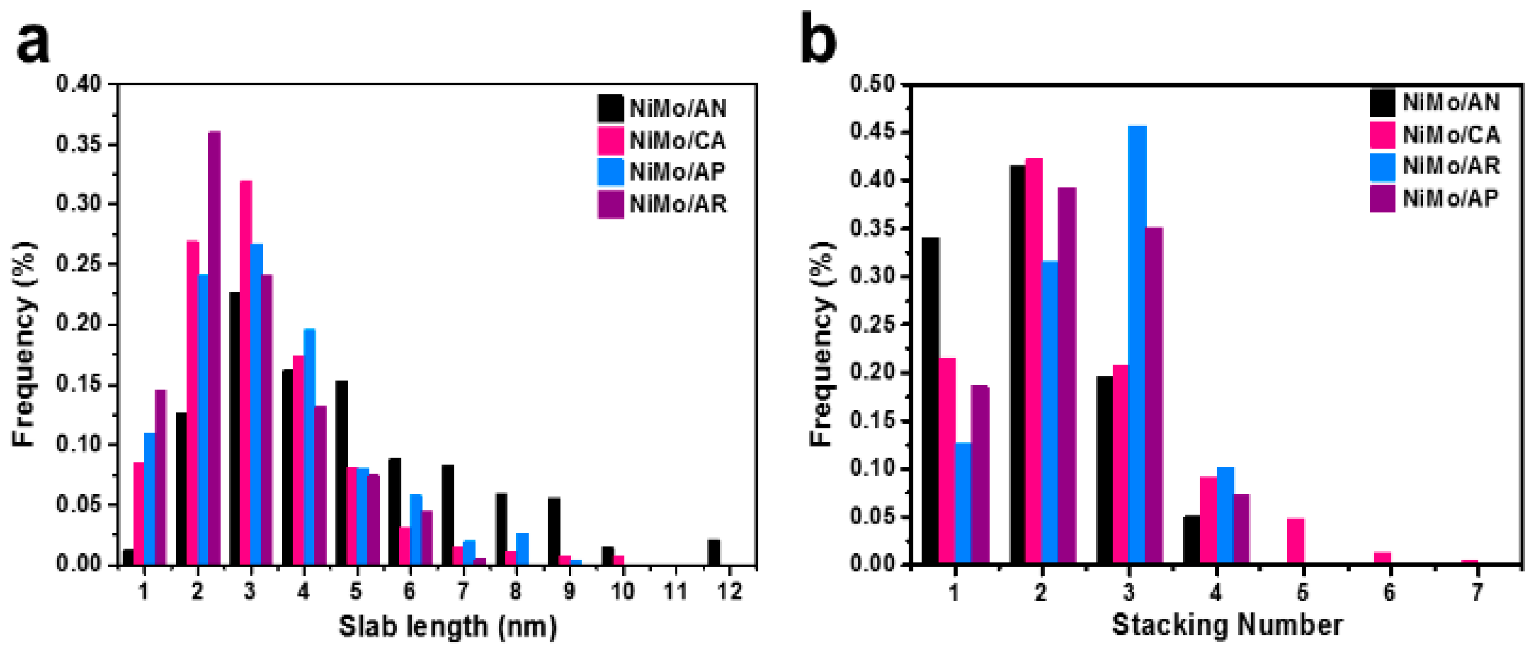
| Catalysts | Ls (nm) a | Nsb | fMoc | Mo/Al d | Ni/(Ni+Mo) d | Mo/Al e |
|---|---|---|---|---|---|---|
| NiMo/AN | 6.14 | 1.96 | 0.13 | 0.077 | 0.45 | 0.046 |
| NiMo/CA | 3.75 | 2.32 | 0.17 | 0.073 | 0.49 | 0.047 |
| NiMo/AH | 3.35 | 2.31 | 0.18 | 0.069 | 0.49 | 0.048 |
| NiMo/AR | 3.87 | 2.53 | 0.17 | 0.068 | 0.53 | 0.046 |
Publisher’s Note: MDPI stays neutral with regard to jurisdictional claims in published maps and institutional affiliations. |
© 2020 by the authors. Licensee MDPI, Basel, Switzerland. This article is an open access article distributed under the terms and conditions of the Creative Commons Attribution (CC BY) license (http://creativecommons.org/licenses/by/4.0/).
Share and Cite
Xu, Y.; Liang, S.; Sun, L.; Hu, X.; Zhang, Y.; Lai, W.; Yi, X.; Fang, W. Management of γ-Alumina with High-Efficient {111} External Surfaces for HDS Reactions. Catalysts 2020, 10, 1254. https://0-doi-org.brum.beds.ac.uk/10.3390/catal10111254
Xu Y, Liang S, Sun L, Hu X, Zhang Y, Lai W, Yi X, Fang W. Management of γ-Alumina with High-Efficient {111} External Surfaces for HDS Reactions. Catalysts. 2020; 10(11):1254. https://0-doi-org.brum.beds.ac.uk/10.3390/catal10111254
Chicago/Turabian StyleXu, Yingrui, Shunqin Liang, Limin Sun, Xiaoli Hu, Yuqi Zhang, Weikun Lai, Xiaodong Yi, and Weiping Fang. 2020. "Management of γ-Alumina with High-Efficient {111} External Surfaces for HDS Reactions" Catalysts 10, no. 11: 1254. https://0-doi-org.brum.beds.ac.uk/10.3390/catal10111254